EP3345526A1 - Appareil de balayage à sec de nettoyage des sols - Google Patents
Appareil de balayage à sec de nettoyage des sols Download PDFInfo
- Publication number
- EP3345526A1 EP3345526A1 EP17207809.9A EP17207809A EP3345526A1 EP 3345526 A1 EP3345526 A1 EP 3345526A1 EP 17207809 A EP17207809 A EP 17207809A EP 3345526 A1 EP3345526 A1 EP 3345526A1
- Authority
- EP
- European Patent Office
- Prior art keywords
- floor
- dust
- scrub
- brushes
- debris
- Prior art date
- Legal status (The legal status is an assumption and is not a legal conclusion. Google has not performed a legal analysis and makes no representation as to the accuracy of the status listed.)
- Granted
Links
Images


Classifications
-
- A—HUMAN NECESSITIES
- A47—FURNITURE; DOMESTIC ARTICLES OR APPLIANCES; COFFEE MILLS; SPICE MILLS; SUCTION CLEANERS IN GENERAL
- A47L—DOMESTIC WASHING OR CLEANING; SUCTION CLEANERS IN GENERAL
- A47L11/00—Machines for cleaning floors, carpets, furniture, walls, or wall coverings
- A47L11/29—Floor-scrubbing machines characterised by means for taking-up dirty liquid
- A47L11/30—Floor-scrubbing machines characterised by means for taking-up dirty liquid by suction
- A47L11/302—Floor-scrubbing machines characterised by means for taking-up dirty liquid by suction having rotary tools
-
- A—HUMAN NECESSITIES
- A47—FURNITURE; DOMESTIC ARTICLES OR APPLIANCES; COFFEE MILLS; SPICE MILLS; SUCTION CLEANERS IN GENERAL
- A47L—DOMESTIC WASHING OR CLEANING; SUCTION CLEANERS IN GENERAL
- A47L11/00—Machines for cleaning floors, carpets, furniture, walls, or wall coverings
- A47L11/28—Floor-scrubbing machines, motor-driven
-
- A—HUMAN NECESSITIES
- A47—FURNITURE; DOMESTIC ARTICLES OR APPLIANCES; COFFEE MILLS; SPICE MILLS; SUCTION CLEANERS IN GENERAL
- A47L—DOMESTIC WASHING OR CLEANING; SUCTION CLEANERS IN GENERAL
- A47L11/00—Machines for cleaning floors, carpets, furniture, walls, or wall coverings
- A47L11/02—Floor surfacing or polishing machines
- A47L11/20—Floor surfacing or polishing machines combined with vacuum cleaning devices
- A47L11/202—Floor surfacing or polishing machines combined with vacuum cleaning devices having separate drive for the cleaning brushes
-
- A—HUMAN NECESSITIES
- A47—FURNITURE; DOMESTIC ARTICLES OR APPLIANCES; COFFEE MILLS; SPICE MILLS; SUCTION CLEANERS IN GENERAL
- A47L—DOMESTIC WASHING OR CLEANING; SUCTION CLEANERS IN GENERAL
- A47L11/00—Machines for cleaning floors, carpets, furniture, walls, or wall coverings
- A47L11/24—Floor-sweeping machines, motor-driven
-
- A—HUMAN NECESSITIES
- A47—FURNITURE; DOMESTIC ARTICLES OR APPLIANCES; COFFEE MILLS; SPICE MILLS; SUCTION CLEANERS IN GENERAL
- A47L—DOMESTIC WASHING OR CLEANING; SUCTION CLEANERS IN GENERAL
- A47L11/00—Machines for cleaning floors, carpets, furniture, walls, or wall coverings
- A47L11/40—Parts or details of machines not provided for in groups A47L11/02 - A47L11/38, or not restricted to one of these groups, e.g. handles, arrangements of switches, skirts, buffers, levers
- A47L11/4013—Contaminants collecting devices, i.e. hoppers, tanks or the like
- A47L11/4016—Contaminants collecting devices, i.e. hoppers, tanks or the like specially adapted for collecting fluids
-
- A—HUMAN NECESSITIES
- A47—FURNITURE; DOMESTIC ARTICLES OR APPLIANCES; COFFEE MILLS; SPICE MILLS; SUCTION CLEANERS IN GENERAL
- A47L—DOMESTIC WASHING OR CLEANING; SUCTION CLEANERS IN GENERAL
- A47L11/00—Machines for cleaning floors, carpets, furniture, walls, or wall coverings
- A47L11/40—Parts or details of machines not provided for in groups A47L11/02 - A47L11/38, or not restricted to one of these groups, e.g. handles, arrangements of switches, skirts, buffers, levers
- A47L11/4036—Parts or details of the surface treating tools
- A47L11/4041—Roll shaped surface treating tools
-
- A—HUMAN NECESSITIES
- A47—FURNITURE; DOMESTIC ARTICLES OR APPLIANCES; COFFEE MILLS; SPICE MILLS; SUCTION CLEANERS IN GENERAL
- A47L—DOMESTIC WASHING OR CLEANING; SUCTION CLEANERS IN GENERAL
- A47L11/00—Machines for cleaning floors, carpets, furniture, walls, or wall coverings
- A47L11/40—Parts or details of machines not provided for in groups A47L11/02 - A47L11/38, or not restricted to one of these groups, e.g. handles, arrangements of switches, skirts, buffers, levers
- A47L11/4036—Parts or details of the surface treating tools
- A47L11/4044—Vacuuming or pick-up tools; Squeegees
-
- A—HUMAN NECESSITIES
- A47—FURNITURE; DOMESTIC ARTICLES OR APPLIANCES; COFFEE MILLS; SPICE MILLS; SUCTION CLEANERS IN GENERAL
- A47L—DOMESTIC WASHING OR CLEANING; SUCTION CLEANERS IN GENERAL
- A47L11/00—Machines for cleaning floors, carpets, furniture, walls, or wall coverings
- A47L11/40—Parts or details of machines not provided for in groups A47L11/02 - A47L11/38, or not restricted to one of these groups, e.g. handles, arrangements of switches, skirts, buffers, levers
- A47L11/408—Means for supplying cleaning or surface treating agents
- A47L11/4083—Liquid supply reservoirs; Preparation of the agents, e.g. mixing devices
-
- A—HUMAN NECESSITIES
- A47—FURNITURE; DOMESTIC ARTICLES OR APPLIANCES; COFFEE MILLS; SPICE MILLS; SUCTION CLEANERS IN GENERAL
- A47L—DOMESTIC WASHING OR CLEANING; SUCTION CLEANERS IN GENERAL
- A47L11/00—Machines for cleaning floors, carpets, furniture, walls, or wall coverings
- A47L11/40—Parts or details of machines not provided for in groups A47L11/02 - A47L11/38, or not restricted to one of these groups, e.g. handles, arrangements of switches, skirts, buffers, levers
- A47L11/408—Means for supplying cleaning or surface treating agents
- A47L11/4088—Supply pumps; Spraying devices; Supply conduits
-
- A—HUMAN NECESSITIES
- A47—FURNITURE; DOMESTIC ARTICLES OR APPLIANCES; COFFEE MILLS; SPICE MILLS; SUCTION CLEANERS IN GENERAL
- A47L—DOMESTIC WASHING OR CLEANING; SUCTION CLEANERS IN GENERAL
- A47L7/00—Suction cleaners adapted for additional purposes; Tables with suction openings for cleaning purposes; Containers for cleaning articles by suction; Suction cleaners adapted to cleaning of brushes; Suction cleaners adapted to taking-up liquids
- A47L7/0004—Suction cleaners adapted to take up liquids, e.g. wet or dry vacuum cleaners
Definitions
- This invention relates generally to apparatus and a method for maintaining and conditioning a generally flat surface, and is particularly directed to the scrubbing and sweeping of a floor surface using a single apparatus which is easily converted between a wet scrubbing/sweeping mode of operation, and a dry sweeping operation without changing or replacing any components or systems.
- Industrial floor scrubbers typically include a cleaning solution tank, a solution delivery system to apply the cleaning solution to the floor in front of one or more rotating cylindrical or disc scrub brushes for cleaning the floor, a squeegee located aft of the scrub brushes for drying the floor, a vacuum system for reclaiming the cleaning solution, and a recovery tank for holding the reclaimed cleaning solution.
- floor scrubbers that employ cylindrical scrub brushes are frequently provided with a debris hopper located aft of the scrub brushes to catch wet debris swept from the floor by the typically counter-rotated scrub brushes.
- a debris hopper located aft of the scrub brushes to catch wet debris swept from the floor by the typically counter-rotated scrub brushes.
- Floor scrubber utility has recently been enhanced so as to provide the scrubber with a dry sweep capability, as opposed to merely scrubbing the floor using a water solution.
- dry sweep systems have been developed for use in some floor scrubbers. These dry sweep systems typically incorporate rubber skirts, or baffles, disposed around the perimeter of the floor engaging scrub brushes for the purpose of containing dust produced during the dry sweep operation.
- These modified floor scrubbers also sometimes include a dust filter mounted to an upper portion of a debris hopper, and a second separate vacuum impeller system to vacuum the debris hopper and draw the dust-laden air through the dust filter, as well as an intermittently operated filter shaker for shaking the filter clean. This system is very similar in operation to a standard dedicated floor sweeper.
- scrubbers used as dry sweepers are not intended to be as effective as a dedicated floor sweeper. If the floor environment is considered to be severe, or "out of control", due to the presence of large amounts of dust and/or debris, then the use of a dedicated floor sweeper is typically recommended to bring the environment under control before scrubbing or scrubber dry sweeping is attempted.
- a further object of the present invention is to replace in a combined mobile floor sweeper and scrubber the use of a dry filter currently used to remove dust from the air flow in the sweeping mode of operation, and to eliminate the problems arising from the use of a water solution with a dry filter by using a water spray system, wherein the dust adheres to fine water particles which are directed into and confined within a solution recovery tank.
- a still further object of the present invention is to position in a combined floor sweeper and scrubber apparatus a debris hopper for recovering floor debris in a manner which prevents (1) debris from getting caught in a rear squeegee, and (2) degradation in the floor cleaning and drying process.
- Yet another object of the present invention is to increase mobile machine floor sweeping reliability and efficiency by reducing operation interruptions and the extent of required servicing arising from the use of a dry dust filter in a water usage and wet debris environment.
- Still another object of the present invention is to provide an integrated dual mode floor scrubber and dry sweeper capable of operating in either mode as a scrubber/sweeper, or solely as a dry sweeper, where operating mode changes are accomplished without adding to or removing any components from the floor scrubber and sweeper.
- the present invention incorporates various improvements in combined wet floor scrubber and drysweeper machines which removes and stores dust and debris removed from the floor using a solution application system and a squeegee arrangement for removing dust and recovering used solution from the floor and eliminating problems associated with the use of a dry dust filter with a solution applied to, and recovered from, the floor.
- Plural flexible skirts, or baffles are positioned around the periphery of a scrub head having a pair of closely spaced, counter-rotating scrub brushes to confine and channel dust removed from the floor. The brushes direct dust and debris removed from the floor rearwardly and upwardly into a debris hopper as in the typical scrubbing operation.
- the dust is directed rearwardly by the skirts to a channel formed by a lower surface of the debris hopper and the floor, with the dust then directed to an aft squeegee disposed in a slightly raised position above the floor.
- a generally vertical squeegee vacuum hose which is also coupled to a vacuum fan, or impeller, for drawing the dust upwardly to a solution recovery tank.
- Water in the form of a mist is directed onto the dust drawn upwardly through the squeegee vacuum hose, with the water particles adhering to and depositing the dust particles in the solution recovery tank.
- a demister disposed in, or adjacent to, an upper portion of the recovery tank separates the remaining water vapor from the air, and the dry air is drawn through the vacuum impeller for discharge from the scrubber/sweeper combination into the atmosphere.
- a combination floor sweeper and scrubber apparatus comprising:
- said rotating scrub brushes are disposed within a substantially closed scrub head.
- said scrub head includes a substantially open lower portion adjacent the floor to provide floor contact for the scrub brushes.
- said plural scrub brushes include first and second closely spaced cylindrical brushes in counter-rotation.
- said first and second cylindrical brushes are aligned generally parallel with the floor and are disposed so as to displace dirt from the floor upwardly between the two brushes.
- said scrub head includes plural skirts disposed adjacent the open lower portion thereof to restrain and direct the dust-laden air rearwardly into engagement with said squeegee.
- said air displacement arrangement draws the dust-laden air aft from said rotating scrub brushes into a channel formed between the floor and a lower portion of said debris tank in the direction of said squeegee.
- the combination floor sweeper and scrubber apparatus includes first forward and second aft cylindrical scrub brushes in lengthwise mutual alignment and aligned generally transverse to the direction of travel of said apparatus during operation.
- said first and second cylindrical scrub brushes are counter-rotating with debris on the floor directed generally upward in a space disposed intermediate said first and second scrub brushes.
- said plural skirts are disposed completely about the open lower portion of said scrub head.
- said rotating scrub brushes slightly pressurize the dust-laden air within said scrub head.
- the pressurized dust-laden air within said scrub head takes a path of least resistance in exiting the scrub head and passing between the top of a rear skirt disposed on said scrub head and front lower edge of said debris hopper.
- a spaced formed between said debris hopper, the floor and plural transport wheels mounted to said apparatus and their associated support structure form a channel for directing the dust-laden air from said scrub head to said squeegee.
- the combination floor sweeper and scrubber apparatus comprises a water pump coupled to said solution storage tank and to said delivery system for distributing the solution throughout the floor sweeper and scrubber apparatus.
- said air displacement arrangement includes a vacuum impeller coupled to said recovery tank for drawing the dust-laden air and water droplets into said recovery tank, wherein said dust-laden water droplets are deposited in said recovery tank and dust-free dry air is drawn from said recovery tank for discharge to the atmosphere by said vacuum impeller.
- the combination floor sweeper and scrubber apparatus comprises a demister disposed within or adjacent to said cleaning solution recovery tank and coupled to said air displacement arrangement for removing moisture from the dust-laden air provided to said recovery tank and providing dry air to said vacuum impeller for discharge to the atmosphere.
- the combination floor sweeper and scrubber apparatus comprises a third suction hose coupling said debris hopper to said first elongated vacuum hose for removing moisture from debris provided to said debris hopper.
- said solution delivery system includes a fourth hose coupled to said solution storage tank for delivery of solution to the floor immediately forward of said plural rotating scrub brushes.
- the combination floor sweeper and scrubber apparatus comprises a fifth hose coupling said debris hopper to said first elongated vacuum hose for removal of moisture from said debris hopper.
- said scrub head further includes movable lateral panels to facilitate access to said cylindrical brushes for maintenance and/or replacement of said brushes.
- said skirts include a first front skirt for confining the debris within said scrub head prior to the scrub brushes directing the dust-laden air and debris rearwardly from said scrub head.
- said skirts include a second rear skirt for directing air-laden dust through a channel formed by the floor and a lower portion of said debris hopper.
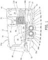
- FIG. 1 there is shown a vertical cross sectional view of a combination floor sweeper and scrubber apparatus 12 in accordance with the present invention taken along the length of the apparatus.
- FIG. 2 is an aft, generally planar view of the inventive floor scrubber dry sweep apparatus 12
- FIG. 3 is a perspective view of a bottom portion of the apparatus illustrating a scrub head 21 including first forward and a second aft rotating scrub brushes 26a and 28a.
- the combination floor sweeper and scrubber apparatus 12 includes a chassis 14 which incorporates the various components and systems described in the following paragraphs.
- the apparatus includes a steering wheel 14a, plural wheels, where one of the front wheels as shown as element 20a which is disposed upon and engages a floor 17.
- the combination floor sweeper and scrubber apparatus 12 further includes an engine 16 for displacing the floor sweeper and scrubber apparatus over the floor 17, as well as a radiator 18 coupled to the engine for controlling the engine's operating temperature.
- a scrub head 21 Disposed in a lower portion of the floor sweeper and scrubber apparatus's chassis 14 is a scrub head 21 which includes a first forward cylindrical rotating scrub brush 26a and a second aft cylindrical rotating scrub brush 28a.
- Forward cylindrical scrub brush 26a rotates in the direction of arrow 26b, while the aft cylindrical scrub brush 28a counter-rotates in the direction of arrow 28b.
- the forward and aft cylindrical scrub brushes 26a and 26a are disposed in contact with the floor 17 and with one another so that the outer peripheral portions of their respective bristles are in contact with one another.
- the inventive floor sweeper and scrubber apparatus 12 further includes a solution tank 22 containing a cleaning solution 22a.
- a solution delivery system is coupled to the solution tank 22 and includes a water pump 66 and a hose system for distributing the solution. More specifically, the solution distribution system includes a first hose section 22b, and second and third hose sections 65 and 67.
- the solution distribution system includes a first hose section 22b, and second and third hose sections 65 and 67.
- solution is delivered from the solution tank 22 via the first hose section 22b through a valve 32 to a first forward solution delivery tube 68a to a portion of the floor 17 immediately forward of the first cylindrical scrub brush 26a.
- the valve 32 is closed and by means of water pump 66, solution is provided from the solution tank 22 via the third hose section 67 to a second aft spray nozzle 68b.
- a debris hopper 30 is disposed in a lower portion of the floor sweeper and scrubber apparatus 14 and aft of the scrub head 21 .
- a forward, upper portion of the debris hopper 30 includes an aperture 30a which is adapted to receive debris removed from the floor 17 and displaced rearwardly by the forward and aft cylindrical scrub brushes 26a and 28a.
- An aperture 30a which is adapted to receive debris removed from the floor 17 and displaced rearwardly by the forward and aft cylindrical scrub brushes 26a and 28a.
- dust removed from the floor 17 is displaced rearwardly by the forward and aft cylindrical scrub brushes 26a, 28a into a channel 63 defined by a lower portion of the debris hopper 30 and the floor 17.
- Rearward displacement of the dust causes the dust to engage a raised rear squeegee 44, which is preferably disposed approximately six inches above the floor 17.
- Squeegee 44 is coupled to the lower end of a rear squeegee vacuum hose 46, which is attached to an aft portion of the chassis 14 and is oriented generally vertically.
- An upper end of the rear squeegee vacuum hose 46 is coupled to an upper portion of a solution recovery tank 24.
- Also coupled to the upper end portion of the recovery tank 24 by means of an air duct 52 is a vacuum impeller, or fan, 56 for drawing clean dry air from the recovery tank 24 for discharge to the atmosphere.
- the solution is directed via the second hose section 65 to water pump 66 which directs the water via the third hose section 67 to aft spray nozzle 68 coupled to the rear squeegee vacuum hose 46 for discharge of the cleaning solution in the form of water droplets onto the dust particles lifted by the vacuum impeller 56 within the rear squeegee vacuum hose in an upward direction.
- This fine water spray encapsulates the dust particles as they travel up the rear squeegee vacuum hose 46 and into the recovery tank 24. Within the recovery tank 24 most of the now wet dust particles are separated from the air flow within the recovery tank by gravity.
- the rear squeegee vacuum hose 46 includes a lower vacuum hose 46a and an upper vacuum hose 46b.
- the debris hopper 30 is coupled to a lower portion of the rear squeegee vacuum hose 46 via a suction hose 77.
- a suction hose 77 When scrubbing a partial vacuum created by the vacuum fan 56 draws moisture from the debris deposited with the debris hopper 30, with this withdrawn moisture then travelling up the rear squeegee vacuum hose 46 to recovery tank 24 for recovery of the used solution and separation of the dry air for discharge to the atmosphere via vacuum fan 56.
- FIG. 2 there is shown an aft planar view of the floor sweeper and scrubber apparatus 12 of the present invention.
- a rear bumper 70 is disposed above the rear squeegee 44 and extends substantially the entire width of the inventive floor sweeper and scrubber apparatus 12, as does the rear squeegee 44.
- the lower rear squeegee vacuum hose 46a extends upwardly from the rear squeegee 44 and is attached to a vacuum hose manifold 74.
- Rear squeegee 44 is shown in the upraised dry sweep positon.
- the lower end portion of the rear squeegee vacuum hose 46 is coupled to the rear squeegee 44, while the upper portion 46b of the rear squeegee vacuum hose is coupled to an upper portion of solution recovery tank 24.
- the vacuum hose manifold 74 is used to connect the upper and lower portions of the rear squeegee vacuum hose 46 as well as the suction hose 77 extending from an aft portion of the debris hopper 30 to the rear squeegee vacuum hose 46.
- Suction hose 77 provides recovered cleaning solution particles from the debris hopper 30 to the rear squeegee vacuum hose 46 for attachment to the dust particles traveling upward in the squeegee vacuum hose 46.
- a left scrub head door 88 and a right scrub head door which is not shown in the figure for simplicity, where the scrub head travels in the direction of arrow 85 during operation.
- Attached to a lower portion of the left scrub head door 88 is a left side door skirt 86 and a left side skirt 87.
- Attached to adjacent lower portions of the right scrub head door is a right side door skirt 84 and a right side skirt 83.
- Each of the left and right scrub head doors includes a pair of handles 90a and 90b adapted for manual engagement so as to be able to open and close the attached scrub head door so as to provide access to the forward and aft cylindrical scrub brushes 26a and 28a for replacement of, or maintenance for, the two scrub brushes disposed within scrub head 21.
- Also disposed on the open lower portion of the scrub head 21 are a front dust skirt 60, a front recirculating skirt 82, and an aft dust recirculating skirt 61. The aforementioned skirts help to contain within the scrub head 21 dust removed from the floor 17 by the forward and aft cylindrical scrub brushes 26a and 28a during dry sweeping.
- Channel 63 is formed by the lower portion of debris hopper 30 and floor 17 in conjunction with the side walls formed by the rear wheels (not shown) and their associated support structure (also not shown). Channel 63 extends substantially to the aft end of the floor sweeper and scrubber apparatus 12. The vacuum created by the vacuum impeller 56 draws the dust-laden air through channel 63 and raised squeegee 44, and then up through the rear squeegee vacuum hose 46.
- Scrub head 21 further includes a generally rectangular frame coupled to and disposed about the forward and aft cylindrical scrub brushes 26a and 28a. Forward and aft cylindrical scrub brushes 26a, 28a are pivotally mounted within the scrub head 21 so as to freely rotate therein under the influence of a rotary drive system which is not shown in the figures for simplicity.
- Forming the right and left lateral portions of the scrub head 21 are left and right scrub head doors, where the left scrub head door is shown as element 88 in FIG. 3 , and the right scrub head door is not shown in the figure for simplicity.
- front dust skirt 60 confines dust removed from the floor 17 within the scrub head 21 prior to its displacement into channel, or tunnel, 63 leading to the rear squeegee 44.
- the aft dust recirculating skirt 61 directs the dust so that it is discharged into the aforementioned channel 63 formed partially by floor 17.
- the front recirculating skirt 82 is also disposed immediately forward of the forward cylindrical scrub brush 26a for confining and directing the dust in a rearward direction as described above.
- Left and right side skirts 87 and 83 are respectively disposed on forward portions of the left side door skirt 86 and the right side door skirt (not shown).
- Each of the left and right scrub head doors includes a respective pair of handles 90a and 90b to facilitate pivotally displacing the left and right scrub head doors outwardly from the scrub head 21 to facilitate access to the forward and aft cylindrical scrub brushes 26a and 28a, as well as access to other system components within the scrub head 21.
- the floor sweeper and scrubber apparatus 12 incorporates an electrical system which interrupts power to a hydraulic solenoid valve that controls the raising and lowering of the rear squeegee 44 relative to floor 17 so that the squeegee remains raised during dry sweep operation of the inventive floor sweeper and scrubber apparatus 12.
- a dry sweep rocker switch is also used to interrupt power to the solution delivery solenoid valves to prevent water flow to the floor forward of the forward and aft cylindrical scrub brushes 26a, 28a also during the dry sweep mode of operation. Electrical power is applied to the dry sweep solution pump 66 for delivering water to the aft spray nozzle 68b attached to the rear squeegee vacuum hose 46.
- the electrical system interrupts delivery of electric power from a 3-position rotary switch to the scrub head floor pressure controller.
- the electrical controller then receives two "OFF" binary signals which activate the electrical controller for applying a "low floor pressure” signal to the scrub head 21.
- Application of the "low floor pressure” signal to the scrub head 21 prevents the operator from choosing the medium and heavy brush pressure settings when in the dry sweep mode of operation.
- the low floor pressure setting is preferred when dry floor sweeping.
- a "low solution" liquid level switch is wired so as to cut off dry sweep operation when the cleaning tank 22 is empty.
Landscapes
- Cleaning In General (AREA)
- Separation Of Particles Using Liquids (AREA)
Applications Claiming Priority (1)
| Application Number | Priority Date | Filing Date | Title |
|---|---|---|---|
| US15/379,805 US9924844B1 (en) | 2016-12-15 | 2016-12-15 | Floor scrubber dry sweep apparatus |
Publications (2)
| Publication Number | Publication Date |
|---|---|
| EP3345526A1 true EP3345526A1 (fr) | 2018-07-11 |
| EP3345526B1 EP3345526B1 (fr) | 2020-01-29 |
Family
ID=60673726
Family Applications (1)
| Application Number | Title | Priority Date | Filing Date |
|---|---|---|---|
| EP17207809.9A Active EP3345526B1 (fr) | 2016-12-15 | 2017-12-15 | Appareil de balayage à sec de nettoyage des sols |
Country Status (8)
| Country | Link |
|---|---|
| US (1) | US9924844B1 (fr) |
| EP (1) | EP3345526B1 (fr) |
| JP (1) | JP2018099512A (fr) |
| KR (1) | KR20180075392A (fr) |
| CN (1) | CN108209754A (fr) |
| AU (1) | AU2017276344A1 (fr) |
| CA (1) | CA2988889C (fr) |
| MX (1) | MX2017016336A (fr) |
Cited By (1)
| Publication number | Priority date | Publication date | Assignee | Title |
|---|---|---|---|---|
| EP3714754A1 (fr) * | 2019-03-28 | 2020-09-30 | Bissell Inc. | Appareil de nettoyage de surface à collecte en deux étapes |
Families Citing this family (12)
| Publication number | Priority date | Publication date | Assignee | Title |
|---|---|---|---|---|
| US11357379B2 (en) * | 2018-05-09 | 2022-06-14 | Nilfisk A/S | Fluid manifolds for floor cleaning machine |
| CN113573621B (zh) * | 2018-12-21 | 2023-09-01 | 坦南特公司 | 能够处理大碎屑的清扫器/擦洗器系统 |
| CN111685660B (zh) * | 2020-05-07 | 2021-09-07 | 苏州品坤智能科技有限公司 | 一种智能化洗地机器人控制系统及工作方法 |
| CN111528724B (zh) * | 2020-06-12 | 2025-03-28 | 苏州市职业大学 | 一种便携式电动擦洗一体装置 |
| CN111700548A (zh) * | 2020-07-04 | 2020-09-25 | 李太祥 | 一种电动免洗拖把 |
| CN113772040B (zh) * | 2021-11-10 | 2022-02-08 | 山东柏远复合材料科技股份有限公司 | 一种船舶甲板清污用设备 |
| CN115299816B (zh) * | 2022-08-16 | 2024-05-03 | 深圳惠优达科技有限公司 | 一种具有空气除湿功能的清洁机器人 |
| CN115467275B (zh) * | 2022-09-02 | 2025-02-28 | 内蒙古千隆电力有限责任公司 | 用于变电站电力运维的监控设备 |
| JP3253888U (ja) * | 2022-12-30 | 2025-12-08 | 北京石頭世紀科技股▲ふん▼有限公司 | 自動清掃装置 |
| USD1105672S1 (en) | 2023-08-30 | 2025-12-09 | Sharkninja Operating Llc | Vacuum cleaner and vacuum nozzle |
| USD1113019S1 (en) | 2024-05-31 | 2026-02-10 | Sharkninja Operating Llc | Steam cleaner |
| WO2025251403A1 (fr) * | 2024-06-04 | 2025-12-11 | 北京石头世纪科技股份有限公司 | Mécanisme de levage/abaissement de roue de locomotion et dispositif de nettoyage |
Citations (3)
| Publication number | Priority date | Publication date | Assignee | Title |
|---|---|---|---|---|
| WO2005107563A1 (fr) * | 2004-05-06 | 2005-11-17 | Tennant Company | Introduction de fluide secondaire dans le système d'aspiration |
| GB2420813A (en) * | 2004-12-06 | 2006-06-07 | Applied Sweepers Ltd | Method for improving the efficiency of cyclone-type air/dirt separation systems in road cleaning machines |
| WO2006121783A1 (fr) * | 2005-05-05 | 2006-11-16 | Tennant Company | Machine a balayer et laver les sols |
Family Cites Families (5)
| Publication number | Priority date | Publication date | Assignee | Title |
|---|---|---|---|---|
| US4819676A (en) | 1986-01-16 | 1989-04-11 | Tennant Company | Combination sweeping and scrubbing system and method |
| US5093955A (en) | 1990-08-29 | 1992-03-10 | Tennant Company | Combined sweeper and scrubber |
| US6662402B2 (en) | 2001-06-20 | 2003-12-16 | Tennant Company | Apparatus for cleaning fabrics, floor coverings, and bare floor surfaces utilizing a soil transfer cleaning medium |
| US7805802B2 (en) * | 2005-10-21 | 2010-10-05 | Tennant Company | Floor cleaning machine debris collection system |
| US8584294B2 (en) | 2005-10-21 | 2013-11-19 | Tennant Company | Floor cleaner scrub head having a movable disc scrub member |
-
2016
- 2016-12-15 US US15/379,805 patent/US9924844B1/en active Active
-
2017
- 2017-12-14 CA CA2988889A patent/CA2988889C/fr active Active
- 2017-12-14 MX MX2017016336A patent/MX2017016336A/es unknown
- 2017-12-14 JP JP2017239869A patent/JP2018099512A/ja active Pending
- 2017-12-15 CN CN201711346903.5A patent/CN108209754A/zh active Pending
- 2017-12-15 KR KR1020170172796A patent/KR20180075392A/ko not_active Withdrawn
- 2017-12-15 AU AU2017276344A patent/AU2017276344A1/en not_active Abandoned
- 2017-12-15 EP EP17207809.9A patent/EP3345526B1/fr active Active
Patent Citations (3)
| Publication number | Priority date | Publication date | Assignee | Title |
|---|---|---|---|---|
| WO2005107563A1 (fr) * | 2004-05-06 | 2005-11-17 | Tennant Company | Introduction de fluide secondaire dans le système d'aspiration |
| GB2420813A (en) * | 2004-12-06 | 2006-06-07 | Applied Sweepers Ltd | Method for improving the efficiency of cyclone-type air/dirt separation systems in road cleaning machines |
| WO2006121783A1 (fr) * | 2005-05-05 | 2006-11-16 | Tennant Company | Machine a balayer et laver les sols |
Cited By (4)
| Publication number | Priority date | Publication date | Assignee | Title |
|---|---|---|---|---|
| EP3714754A1 (fr) * | 2019-03-28 | 2020-09-30 | Bissell Inc. | Appareil de nettoyage de surface à collecte en deux étapes |
| EP3854283A1 (fr) | 2019-03-28 | 2021-07-28 | Bissell Inc. | Appareil de nettoyage de surfaces avec collecte en deux étapes |
| EP3854284A1 (fr) | 2019-03-28 | 2021-07-28 | Bissell Inc. | Appareil de nettoyage de surfaces avec collecte en deux étapes |
| US11540689B2 (en) | 2019-03-28 | 2023-01-03 | Bissell Inc. | Surface cleaning apparatus with two-stage collection |
Also Published As
| Publication number | Publication date |
|---|---|
| MX2017016336A (es) | 2018-11-09 |
| CA2988889A1 (fr) | 2018-06-15 |
| JP2018099512A (ja) | 2018-06-28 |
| US9924844B1 (en) | 2018-03-27 |
| KR20180075392A (ko) | 2018-07-04 |
| AU2017276344A1 (en) | 2018-07-05 |
| EP3345526B1 (fr) | 2020-01-29 |
| CA2988889C (fr) | 2024-01-02 |
| CN108209754A (zh) | 2018-06-29 |
Similar Documents
| Publication | Publication Date | Title |
|---|---|---|
| EP3345526B1 (fr) | Appareil de balayage à sec de nettoyage des sols | |
| CN113633231B (zh) | 一种清洁头及表面清洁设备 | |
| US7448114B2 (en) | Floor sweeping and scrubbing machine | |
| CN1268273C (zh) | 具有空气搅动的机器人真空吸尘器 | |
| EP1753335B1 (fr) | Introduction de fluide secondaire dans le système d'aspiration | |
| CA1186110A (fr) | Machine de brossage a selecteur de recyclage | |
| US9968231B2 (en) | Floor cleaning head | |
| CN107313376A (zh) | 一种吸尘、洗地、烘干一体机 | |
| KR200476875Y1 (ko) | 전기 청소 및 세척 장치 | |
| KR101584794B1 (ko) | 건식 노면 청소차용 청소장치 | |
| WO2017025032A1 (fr) | Robot de nettoyage automobile | |
| CN107072459B (zh) | 具有用于捕集残留废物的集成水捕集器的表面维护车辆 | |
| CN102599868A (zh) | 洗涤干燥擦洗机 | |
| CN109303523A (zh) | 地面扫洗吸一体机的除尘系统 | |
| EP2463441B1 (fr) | Dispositif de lutte contre la poussière | |
| CN109351711A (zh) | 用于太阳能电池板的清洗机 | |
| CN105451623B (zh) | 具有捕获软管残水的自清洁储器的表面养护车辆 | |
| US20090078281A1 (en) | Floor Cleaning Apparatus With Surface Dryer | |
| KR100635641B1 (ko) | 세척수가 비산되는 로봇 청소기 | |
| CN112832180A (zh) | 一种具有清扫洒水拖干功能的清扫车 | |
| US20140338147A1 (en) | Dust suctioning pick-up head apparatus for use with a sweeping vehicle | |
| CN109349968B (zh) | 地面扫洗吸一体机 | |
| CN119584909A (zh) | 基站及清洁系统 | |
| CA2299657A1 (fr) | Vehicule de nettoyage mecanique des surfaces permettant l'elimination des particules fines | |
| JP2006305052A (ja) | 付着物除去装置 |
Legal Events
| Date | Code | Title | Description |
|---|---|---|---|
| PUAI | Public reference made under article 153(3) epc to a published international application that has entered the european phase |
Free format text: ORIGINAL CODE: 0009012 |
|
| STAA | Information on the status of an ep patent application or granted ep patent |
Free format text: STATUS: THE APPLICATION HAS BEEN PUBLISHED |
|
| AK | Designated contracting states |
Kind code of ref document: A1 Designated state(s): AL AT BE BG CH CY CZ DE DK EE ES FI FR GB GR HR HU IE IS IT LI LT LU LV MC MK MT NL NO PL PT RO RS SE SI SK SM TR |
|
| AX | Request for extension of the european patent |
Extension state: BA ME |
|
| STAA | Information on the status of an ep patent application or granted ep patent |
Free format text: STATUS: REQUEST FOR EXAMINATION WAS MADE |
|
| 17P | Request for examination filed |
Effective date: 20190225 |
|
| RBV | Designated contracting states (corrected) |
Designated state(s): AL AT BE BG CH CY CZ DE DK EE ES FI FR GB GR HR HU IE IS IT LI LT LU LV MC MK MT NL NO PL PT RO RS SE SI SK SM TR |
|
| GRAP | Despatch of communication of intention to grant a patent |
Free format text: ORIGINAL CODE: EPIDOSNIGR1 |
|
| STAA | Information on the status of an ep patent application or granted ep patent |
Free format text: STATUS: GRANT OF PATENT IS INTENDED |
|
| INTG | Intention to grant announced |
Effective date: 20190718 |
|
| GRAS | Grant fee paid |
Free format text: ORIGINAL CODE: EPIDOSNIGR3 |
|
| GRAJ | Information related to disapproval of communication of intention to grant by the applicant or resumption of examination proceedings by the epo deleted |
Free format text: ORIGINAL CODE: EPIDOSDIGR1 |
|
| GRAL | Information related to payment of fee for publishing/printing deleted |
Free format text: ORIGINAL CODE: EPIDOSDIGR3 |
|
| STAA | Information on the status of an ep patent application or granted ep patent |
Free format text: STATUS: REQUEST FOR EXAMINATION WAS MADE |
|
| GRAR | Information related to intention to grant a patent recorded |
Free format text: ORIGINAL CODE: EPIDOSNIGR71 |
|
| STAA | Information on the status of an ep patent application or granted ep patent |
Free format text: STATUS: GRANT OF PATENT IS INTENDED |
|
| INTC | Intention to grant announced (deleted) | ||
| GRAA | (expected) grant |
Free format text: ORIGINAL CODE: 0009210 |
|
| STAA | Information on the status of an ep patent application or granted ep patent |
Free format text: STATUS: THE PATENT HAS BEEN GRANTED |
|
| INTG | Intention to grant announced |
Effective date: 20191212 |
|
| AK | Designated contracting states |
Kind code of ref document: B1 Designated state(s): AL AT BE BG CH CY CZ DE DK EE ES FI FR GB GR HR HU IE IS IT LI LT LU LV MC MK MT NL NO PL PT RO RS SE SI SK SM TR |
|
| REG | Reference to a national code |
Ref country code: GB Ref legal event code: FG4D |
|
| REG | Reference to a national code |
Ref country code: CH Ref legal event code: EP |
|
| REG | Reference to a national code |
Ref country code: AT Ref legal event code: REF Ref document number: 1227903 Country of ref document: AT Kind code of ref document: T Effective date: 20200215 |
|
| REG | Reference to a national code |
Ref country code: IE Ref legal event code: FG4D |
|
| REG | Reference to a national code |
Ref country code: DE Ref legal event code: R096 Ref document number: 602017011173 Country of ref document: DE |
|
| REG | Reference to a national code |
Ref country code: CH Ref legal event code: NV Representative=s name: CRONIN INTELLECTUAL PROPERTY, CH |
|
| REG | Reference to a national code |
Ref country code: NL Ref legal event code: MP Effective date: 20200129 |
|
| PG25 | Lapsed in a contracting state [announced via postgrant information from national office to epo] |
Ref country code: RS Free format text: LAPSE BECAUSE OF FAILURE TO SUBMIT A TRANSLATION OF THE DESCRIPTION OR TO PAY THE FEE WITHIN THE PRESCRIBED TIME-LIMIT Effective date: 20200129 Ref country code: NO Free format text: LAPSE BECAUSE OF FAILURE TO SUBMIT A TRANSLATION OF THE DESCRIPTION OR TO PAY THE FEE WITHIN THE PRESCRIBED TIME-LIMIT Effective date: 20200429 Ref country code: FI Free format text: LAPSE BECAUSE OF FAILURE TO SUBMIT A TRANSLATION OF THE DESCRIPTION OR TO PAY THE FEE WITHIN THE PRESCRIBED TIME-LIMIT Effective date: 20200129 Ref country code: PT Free format text: LAPSE BECAUSE OF FAILURE TO SUBMIT A TRANSLATION OF THE DESCRIPTION OR TO PAY THE FEE WITHIN THE PRESCRIBED TIME-LIMIT Effective date: 20200621 |
|
| REG | Reference to a national code |
Ref country code: LT Ref legal event code: MG4D |
|
| PG25 | Lapsed in a contracting state [announced via postgrant information from national office to epo] |
Ref country code: HR Free format text: LAPSE BECAUSE OF FAILURE TO SUBMIT A TRANSLATION OF THE DESCRIPTION OR TO PAY THE FEE WITHIN THE PRESCRIBED TIME-LIMIT Effective date: 20200129 Ref country code: IS Free format text: LAPSE BECAUSE OF FAILURE TO SUBMIT A TRANSLATION OF THE DESCRIPTION OR TO PAY THE FEE WITHIN THE PRESCRIBED TIME-LIMIT Effective date: 20200529 Ref country code: SE Free format text: LAPSE BECAUSE OF FAILURE TO SUBMIT A TRANSLATION OF THE DESCRIPTION OR TO PAY THE FEE WITHIN THE PRESCRIBED TIME-LIMIT Effective date: 20200129 Ref country code: LV Free format text: LAPSE BECAUSE OF FAILURE TO SUBMIT A TRANSLATION OF THE DESCRIPTION OR TO PAY THE FEE WITHIN THE PRESCRIBED TIME-LIMIT Effective date: 20200129 Ref country code: BG Free format text: LAPSE BECAUSE OF FAILURE TO SUBMIT A TRANSLATION OF THE DESCRIPTION OR TO PAY THE FEE WITHIN THE PRESCRIBED TIME-LIMIT Effective date: 20200429 Ref country code: GR Free format text: LAPSE BECAUSE OF FAILURE TO SUBMIT A TRANSLATION OF THE DESCRIPTION OR TO PAY THE FEE WITHIN THE PRESCRIBED TIME-LIMIT Effective date: 20200430 |
|
| PG25 | Lapsed in a contracting state [announced via postgrant information from national office to epo] |
Ref country code: NL Free format text: LAPSE BECAUSE OF FAILURE TO SUBMIT A TRANSLATION OF THE DESCRIPTION OR TO PAY THE FEE WITHIN THE PRESCRIBED TIME-LIMIT Effective date: 20200129 |
|
| PG25 | Lapsed in a contracting state [announced via postgrant information from national office to epo] |
Ref country code: EE Free format text: LAPSE BECAUSE OF FAILURE TO SUBMIT A TRANSLATION OF THE DESCRIPTION OR TO PAY THE FEE WITHIN THE PRESCRIBED TIME-LIMIT Effective date: 20200129 Ref country code: SM Free format text: LAPSE BECAUSE OF FAILURE TO SUBMIT A TRANSLATION OF THE DESCRIPTION OR TO PAY THE FEE WITHIN THE PRESCRIBED TIME-LIMIT Effective date: 20200129 Ref country code: RO Free format text: LAPSE BECAUSE OF FAILURE TO SUBMIT A TRANSLATION OF THE DESCRIPTION OR TO PAY THE FEE WITHIN THE PRESCRIBED TIME-LIMIT Effective date: 20200129 Ref country code: CZ Free format text: LAPSE BECAUSE OF FAILURE TO SUBMIT A TRANSLATION OF THE DESCRIPTION OR TO PAY THE FEE WITHIN THE PRESCRIBED TIME-LIMIT Effective date: 20200129 Ref country code: SK Free format text: LAPSE BECAUSE OF FAILURE TO SUBMIT A TRANSLATION OF THE DESCRIPTION OR TO PAY THE FEE WITHIN THE PRESCRIBED TIME-LIMIT Effective date: 20200129 Ref country code: ES Free format text: LAPSE BECAUSE OF FAILURE TO SUBMIT A TRANSLATION OF THE DESCRIPTION OR TO PAY THE FEE WITHIN THE PRESCRIBED TIME-LIMIT Effective date: 20200129 Ref country code: LT Free format text: LAPSE BECAUSE OF FAILURE TO SUBMIT A TRANSLATION OF THE DESCRIPTION OR TO PAY THE FEE WITHIN THE PRESCRIBED TIME-LIMIT Effective date: 20200129 Ref country code: DK Free format text: LAPSE BECAUSE OF FAILURE TO SUBMIT A TRANSLATION OF THE DESCRIPTION OR TO PAY THE FEE WITHIN THE PRESCRIBED TIME-LIMIT Effective date: 20200129 |
|
| REG | Reference to a national code |
Ref country code: DE Ref legal event code: R097 Ref document number: 602017011173 Country of ref document: DE |
|
| REG | Reference to a national code |
Ref country code: AT Ref legal event code: MK05 Ref document number: 1227903 Country of ref document: AT Kind code of ref document: T Effective date: 20200129 |
|
| PLBE | No opposition filed within time limit |
Free format text: ORIGINAL CODE: 0009261 |
|
| STAA | Information on the status of an ep patent application or granted ep patent |
Free format text: STATUS: NO OPPOSITION FILED WITHIN TIME LIMIT |
|
| 26N | No opposition filed |
Effective date: 20201030 |
|
| PG25 | Lapsed in a contracting state [announced via postgrant information from national office to epo] |
Ref country code: AT Free format text: LAPSE BECAUSE OF FAILURE TO SUBMIT A TRANSLATION OF THE DESCRIPTION OR TO PAY THE FEE WITHIN THE PRESCRIBED TIME-LIMIT Effective date: 20200129 Ref country code: IT Free format text: LAPSE BECAUSE OF FAILURE TO SUBMIT A TRANSLATION OF THE DESCRIPTION OR TO PAY THE FEE WITHIN THE PRESCRIBED TIME-LIMIT Effective date: 20200129 |
|
| PG25 | Lapsed in a contracting state [announced via postgrant information from national office to epo] |
Ref country code: PL Free format text: LAPSE BECAUSE OF FAILURE TO SUBMIT A TRANSLATION OF THE DESCRIPTION OR TO PAY THE FEE WITHIN THE PRESCRIBED TIME-LIMIT Effective date: 20200129 Ref country code: SI Free format text: LAPSE BECAUSE OF FAILURE TO SUBMIT A TRANSLATION OF THE DESCRIPTION OR TO PAY THE FEE WITHIN THE PRESCRIBED TIME-LIMIT Effective date: 20200129 |
|
| PG25 | Lapsed in a contracting state [announced via postgrant information from national office to epo] |
Ref country code: MC Free format text: LAPSE BECAUSE OF FAILURE TO SUBMIT A TRANSLATION OF THE DESCRIPTION OR TO PAY THE FEE WITHIN THE PRESCRIBED TIME-LIMIT Effective date: 20200129 |
|
| REG | Reference to a national code |
Ref country code: BE Ref legal event code: MM Effective date: 20201231 |
|
| PG25 | Lapsed in a contracting state [announced via postgrant information from national office to epo] |
Ref country code: IE Free format text: LAPSE BECAUSE OF NON-PAYMENT OF DUE FEES Effective date: 20201215 Ref country code: LU Free format text: LAPSE BECAUSE OF NON-PAYMENT OF DUE FEES Effective date: 20201215 |
|
| PGFP | Annual fee paid to national office [announced via postgrant information from national office to epo] |
Ref country code: CH Payment date: 20220104 Year of fee payment: 5 |
|
| PG25 | Lapsed in a contracting state [announced via postgrant information from national office to epo] |
Ref country code: TR Free format text: LAPSE BECAUSE OF FAILURE TO SUBMIT A TRANSLATION OF THE DESCRIPTION OR TO PAY THE FEE WITHIN THE PRESCRIBED TIME-LIMIT Effective date: 20200129 Ref country code: MT Free format text: LAPSE BECAUSE OF FAILURE TO SUBMIT A TRANSLATION OF THE DESCRIPTION OR TO PAY THE FEE WITHIN THE PRESCRIBED TIME-LIMIT Effective date: 20200129 Ref country code: CY Free format text: LAPSE BECAUSE OF FAILURE TO SUBMIT A TRANSLATION OF THE DESCRIPTION OR TO PAY THE FEE WITHIN THE PRESCRIBED TIME-LIMIT Effective date: 20200129 |
|
| PG25 | Lapsed in a contracting state [announced via postgrant information from national office to epo] |
Ref country code: MK Free format text: LAPSE BECAUSE OF FAILURE TO SUBMIT A TRANSLATION OF THE DESCRIPTION OR TO PAY THE FEE WITHIN THE PRESCRIBED TIME-LIMIT Effective date: 20200129 Ref country code: AL Free format text: LAPSE BECAUSE OF FAILURE TO SUBMIT A TRANSLATION OF THE DESCRIPTION OR TO PAY THE FEE WITHIN THE PRESCRIBED TIME-LIMIT Effective date: 20200129 |
|
| PG25 | Lapsed in a contracting state [announced via postgrant information from national office to epo] |
Ref country code: BE Free format text: LAPSE BECAUSE OF NON-PAYMENT OF DUE FEES Effective date: 20201231 |
|
| P01 | Opt-out of the competence of the unified patent court (upc) registered |
Effective date: 20230525 |
|
| REG | Reference to a national code |
Ref country code: CH Ref legal event code: PL |
|
| PG25 | Lapsed in a contracting state [announced via postgrant information from national office to epo] |
Ref country code: LI Free format text: LAPSE BECAUSE OF NON-PAYMENT OF DUE FEES Effective date: 20221231 Ref country code: CH Free format text: LAPSE BECAUSE OF NON-PAYMENT OF DUE FEES Effective date: 20221231 |
|
| PGFP | Annual fee paid to national office [announced via postgrant information from national office to epo] |
Ref country code: GB Payment date: 20251229 Year of fee payment: 9 |
|
| PGFP | Annual fee paid to national office [announced via postgrant information from national office to epo] |
Ref country code: FR Payment date: 20251226 Year of fee payment: 9 |
|
| REG | Reference to a national code |
Ref country code: DE Ref legal event code: R082 Ref document number: 602017011173 Country of ref document: DE Representative=s name: PUSCHMANN BORCHERT KAISER KLETTNER PATENTANWAE, DE Ref country code: DE Ref legal event code: R082 Ref document number: 602017011173 Country of ref document: DE Representative=s name: PATCARE PATENTANWAELTE PARTNERSCHAFT MBB, DE |
|
| PGFP | Annual fee paid to national office [announced via postgrant information from national office to epo] |
Ref country code: DE Payment date: 20251229 Year of fee payment: 9 |