EP3345546B1 - Appareil à fenêtre pulmonaire basé sur la microaspiration pour l'obtention d'une image microscopique in vivo de tissu pulmonaire - Google Patents
Appareil à fenêtre pulmonaire basé sur la microaspiration pour l'obtention d'une image microscopique in vivo de tissu pulmonaire Download PDFInfo
- Publication number
- EP3345546B1 EP3345546B1 EP16842282.2A EP16842282A EP3345546B1 EP 3345546 B1 EP3345546 B1 EP 3345546B1 EP 16842282 A EP16842282 A EP 16842282A EP 3345546 B1 EP3345546 B1 EP 3345546B1
- Authority
- EP
- European Patent Office
- Prior art keywords
- lung
- window
- open window
- open
- microaspiration
- Prior art date
- Legal status (The legal status is an assumption and is not a legal conclusion. Google has not performed a legal analysis and makes no representation as to the accuracy of the status listed.)
- Active
Links
Images


Classifications
-
- G—PHYSICS
- G02—OPTICS
- G02B—OPTICAL ELEMENTS, SYSTEMS OR APPARATUS
- G02B21/00—Microscopes
- G02B21/36—Microscopes arranged for photographic purposes or projection purposes or digital imaging or video purposes including associated control and data processing arrangements
- G02B21/362—Mechanical details, e.g. mountings for the camera or image sensor, housings
-
- A—HUMAN NECESSITIES
- A61—MEDICAL OR VETERINARY SCIENCE; HYGIENE
- A61B—DIAGNOSIS; SURGERY; IDENTIFICATION
- A61B5/00—Measuring for diagnostic purposes; Identification of persons
- A61B5/68—Arrangements of detecting, measuring or recording means, e.g. sensors, in relation to patient
- A61B5/6846—Arrangements of detecting, measuring or recording means, e.g. sensors, in relation to patient specially adapted to be brought in contact with an internal body part, i.e. invasive
- A61B5/6886—Monitoring or controlling distance between sensor and tissue
-
- A—HUMAN NECESSITIES
- A61—MEDICAL OR VETERINARY SCIENCE; HYGIENE
- A61B—DIAGNOSIS; SURGERY; IDENTIFICATION
- A61B5/00—Measuring for diagnostic purposes; Identification of persons
-
- A—HUMAN NECESSITIES
- A61—MEDICAL OR VETERINARY SCIENCE; HYGIENE
- A61B—DIAGNOSIS; SURGERY; IDENTIFICATION
- A61B5/00—Measuring for diagnostic purposes; Identification of persons
- A61B5/0059—Measuring for diagnostic purposes; Identification of persons using light, e.g. diagnosis by transillumination, diascopy, fluorescence
- A61B5/0082—Measuring for diagnostic purposes; Identification of persons using light, e.g. diagnosis by transillumination, diascopy, fluorescence adapted for particular medical purposes
- A61B5/0084—Measuring for diagnostic purposes; Identification of persons using light, e.g. diagnosis by transillumination, diascopy, fluorescence adapted for particular medical purposes for introduction into the body, e.g. by catheters
-
- A—HUMAN NECESSITIES
- A61—MEDICAL OR VETERINARY SCIENCE; HYGIENE
- A61B—DIAGNOSIS; SURGERY; IDENTIFICATION
- A61B5/00—Measuring for diagnostic purposes; Identification of persons
- A61B5/08—Measuring devices for evaluating the respiratory organs
-
- A—HUMAN NECESSITIES
- A61—MEDICAL OR VETERINARY SCIENCE; HYGIENE
- A61B—DIAGNOSIS; SURGERY; IDENTIFICATION
- A61B5/00—Measuring for diagnostic purposes; Identification of persons
- A61B5/08—Measuring devices for evaluating the respiratory organs
- A61B5/0803—Recording apparatus specially adapted therefor
-
- G—PHYSICS
- G02—OPTICS
- G02B—OPTICAL ELEMENTS, SYSTEMS OR APPARATUS
- G02B21/00—Microscopes
-
- G—PHYSICS
- G02—OPTICS
- G02B—OPTICAL ELEMENTS, SYSTEMS OR APPARATUS
- G02B21/00—Microscopes
- G02B21/0004—Microscopes specially adapted for specific applications
- G02B21/0012—Surgical microscopes
-
- G—PHYSICS
- G02—OPTICS
- G02B—OPTICAL ELEMENTS, SYSTEMS OR APPARATUS
- G02B21/00—Microscopes
- G02B21/36—Microscopes arranged for photographic purposes or projection purposes or digital imaging or video purposes including associated control and data processing arrangements
-
- A—HUMAN NECESSITIES
- A61—MEDICAL OR VETERINARY SCIENCE; HYGIENE
- A61B—DIAGNOSIS; SURGERY; IDENTIFICATION
- A61B5/00—Measuring for diagnostic purposes; Identification of persons
- A61B5/0059—Measuring for diagnostic purposes; Identification of persons using light, e.g. diagnosis by transillumination, diascopy, fluorescence
- A61B5/0071—Measuring for diagnostic purposes; Identification of persons using light, e.g. diagnosis by transillumination, diascopy, fluorescence by measuring fluorescence emission
-
- G—PHYSICS
- G02—OPTICS
- G02B—OPTICAL ELEMENTS, SYSTEMS OR APPARATUS
- G02B21/00—Microscopes
- G02B21/36—Microscopes arranged for photographic purposes or projection purposes or digital imaging or video purposes including associated control and data processing arrangements
- G02B21/361—Optical details, e.g. image relay to the camera or image sensor
Definitions
- the present disclosure relates to a microaspiration-based lung window apparatus for obtaining a microscopic image of a lung tissue in vivo and a method for obtaining an image using the same.
- a confocal laser scanning microscope using fluorescent signals is used to observe cellular-level and molecular-level phenomenon.
- the pulmonary system Unlike other tissues, the pulmonary system periodically moves due to the respiration process and the beating of the heart close to it, thus due to such motion artifacts it is difficult to obtain accurate images when wishing to obtain microscopic images.
- WO 2013/109624 A2 discloses methods and materials involved in obtaining images using probe-based Confocal Laser Endomicroscopy (pCLE).
- pCLE devices are configured to allow a user to stabilize imaging probes in a manner that minimizes excessive movement during imaging are provided.
- the device includes an inner catheter element and an imaging probe.
- the inner catheter element is configured to be located at least partially within an outer hollow member.
- a proximal end region of inner catheter element includes a suction port configured to allow suction force to be applied to the inner catheter element.
- the device can be introduced into a mammal and the inner catheter element can be introduced into the mammal by advancing the inner catheter element within the device.
- suction force can be applied to the suction port of the inner catheter element while the user holds a finger or thumb over a suction release opening of the inner catheter element. This can allow the distal end of the inner catheter element to engage tissue to be imaged in a manner that minimizes excessive movement of the imaging probe during imaging.
- US 2010/081964 A1 discloses a system for detecting abnormal tissue in a patient including an introducer cannula having a proximal opening and a distal opening.
- the system comprises a sensor, an analysis system and an output portion.
- the sensor may include optical components including a light source, a lens, and/or a light detector.
- the sensor (110) is part of a sensing unit, which is configured as part of an inner cannula of a "cannula-within-a-cannula" surgical resection device.
- a vacuum can be developed between an outer cannula and the inner cannula to draw the tissue to vacuum holes and to the sensor.
- the present disclosure provides a microaspiration-based lung window apparatus for obtaining a microscopic image of an in vivo lung tissue and a method that is not part of the invention for obtaining an image using the same, the apparatus and method being able to stably obtain cellular-level and molecular-level microscopic images of a lung tissue in vivo while physiologically maintaining and not interfering with respiration and circulation of an animal.
- a microaspiration-based lung window apparatus for obtaining a microscopic image of a lung tissue in vivo, the apparatus comprising: an open window configured to open in upper and lower parts thereof, have a cover glass placed on the upper part thereof, and have a lung tissue brought in contact with the lower part thereof; a suction tube configured to extend to a suction device from a side of the open window and make the inside of the open window vacuum; and a tilting mount seat, configured to extend from a side of the open window, in which a tilting mount is placed to maintain the cover glass and an objective lens of a confocal microscope system in parallel.
- a microaspiration-based lung window apparatus for obtaining a microscopic image of a lung tissue in vivo, the apparatus consisting of: an open window configured to open in upper and lower parts thereof, have a cover glass placed on the upper part thereof, and have a lung tissue brought in contact with the lower part thereof; a suction tube configured to extend to a suction device from a side of the open window and make the inside of the open window vacuum; and a tilting mount seat, configured to extend from a side of the open window, in which a tilting mount is placed to maintain the cover glass and an objective lens of a confocal microscope system in parallel.
- a microaspiration-based lung window apparatus for obtaining a microscopic image of a lung tissue in vivo, the apparatus essentially consisting of: an open window configured to open in upper and lower parts thereof, have a cover glass placed on the upper part thereof, and have a lung tissue brought in contact with the lower part thereof; a suction tube configured to extend to a suction device from a side of the open window and make the inside of the open window vacuum; and a tilting mount seat, configured to extend from a side of the open window, in which a tilting mount is placed to maintain the cover glass and an objective lens of a confocal microscope system in parallel.
- the open window may have a conical shape of which a diameter is increased from its upper part to its lower part.
- the tilting mount seat may have a plurality of fastening holes for coupling the tilting mount.
- the open window and the suction tube are formed in a first plate which has a first body and first protrusions having a step with respect to the first body and protrudes from sides of the first body, and the tilting mount seat is formed in a second plate which has a second body and second protrusions having a step with respect to the second body and joining with the first protrusions.
- a microaspiration-based lung window apparatus for obtaining a microscopic image of an lung tissue in vivo, the apparatus comprising: a first plate in which an open window and a suction tube are formed, wherein the open window is configured to open in upper and lower parts thereof, have a cover glass placed on the upper part thereof, and have a lung tissue brought in contact with the lower part thereof, wherein the suction tube is configured to extend to a suction device from a side of the open window and make the inside of the open window vacuum; and a second plate, which is configured to join with the first plate, where there is formed a tilting mount seat in which a tilting mount is placed to maintain the cover glass and an objective lens of a confocal microscope system in parallel.
- a microaspiration-based lung window apparatus for obtaining a microscopic image of an lung tissue in vivo, the apparatus consisting of: a first plate in which an open window and a suction tube are formed, wherein the open window is configured to open in upper and lower parts thereof, have a cover glass placed on the upper part thereof, and have a lung tissue brought in contact with the lower part thereof, wherein the suction tube is configured to extend to a suction device from a side of the open window and make the inside of the open window vacuum; and a second plate, which is configured to join with the first plate, where there is formed a tilting mount seat in which a tilting mount is placed to maintain the cover glass and an objective lens of a confocal microscope system in parallel.
- a microaspiration-based lung window apparatus for obtaining a microscopic image of an lung tissue in vivo, the apparatus essentially consisting of: a first plate in which an open window and a suction tube are formed, wherein the open window is configured to open in upper and lower parts thereof, have a cover glass placed on the upper part thereof, and have a lung tissue brought in contact with the lower part thereof, wherein the suction tube is configured to extend to a suction device from a side of the open window and make the inside of the open window vacuum; and a second plate, which is configured to join with the first plate, where there is formed a tilting mount seat in which a tilting mount is placed to maintain the cover glass and an objective lens of a confocal microscope system in parallel.
- a method of obtaining an image using a confocal microscope system and a microscopic aspiration-based lung window apparatus comprising: adjusting the angle of the lung window apparatus by using a tilting mount placed on a tilting mount seat of the lung window apparatus; radiating laser beams having a plurality of wavelengths to a lung tissue through an open window of the lung window apparatus, wherein a cover glass is placed over the upper part of the open window, the lung tissue is brought in contact with the lower part of the open window, a suction tube extending to a suction device is formed on a side of the open window, so as to keep the inside of the open window vacuum; and detecting a fluorescent signal excited in the lung tissue, wherein the cover glass placed over the open window and an objective lens of the confocal microscope system are maintained in parallel in a respiration or circulation process by adjusting the angle of the tilting mount.
- a method of obtaining an image using a confocal microscope system and a microscopic aspiration-based lung window apparatus consisting of: adjusting the angle of the lung window apparatus by using a tilting mount placed on a tilting mount seat of the lung window apparatus; radiating laser beams having a plurality of wavelengths to a lung tissue through an open window of the lung window apparatus, wherein a cover glass is placed over the upper part of the open window, the lung tissue is brought in contact with the lower part of the open window, a suction tube extending to a suction device is formed on a side of the open window, so as to keep the inside of the open window vacuum; and detecting a fluorescent signal excited in the lung tissue, wherein the cover glass placed over the open window and an objective lens of the confocal microscope system are maintained in parallel in a respiration or circulation process by adjusting the angle of the tilting mount.
- a method of obtaining an image using a confocal microscope system and a microscopic aspiration-based lung window apparatus the method essentially consisting of: adjusting the angle of the lung window apparatus by using a tilting mount placed on a tilting mount seat of the lung window apparatus; radiating laser beams having a plurality of wavelengths to a lung tissue through an open window of the lung window apparatus, wherein a cover glass is placed over the upper part of the open window, the lung tissue is brought in contact with the lower part of the open window, a suction tube extending to a suction device is formed on a side of the open window, so as to keep the inside of the open window vacuum; and detecting a fluorescent signal excited in the lung tissue, wherein the cover glass placed over the open window and an objective lens of the confocal microscope system are maintained in parallel in a respiration or circulation process by adjusting the angle of the tilting mount.
- an open window that is attached to a lung tissue and placed close to an object lens and a seat that extends from the open window and on which a tilting mount is mounted are provided, and the open window and the objective lens can be maintained in parallel during respiration and circulation on an animal, so it is possible to obtain stable images.
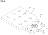
- FIG. 1 is a perspective view showing a long window apparatus according to an embodiment
- FIG. 2 is a view showing the lung window apparatus according to an embodiment when it is separated
- FIG. 3 shows a front view and a bottom view of the lung window apparatus according to an embodiment
- FIG. 4 shows a vertical cross-sectional view of the lung window apparatus according to an embodiment.
- a lung window apparatus may include an open window 100, a suction tube 102, and a tilting mount seat 104.
- the open window has a conical shape with open top and bottom and a diameter is increased from its upper part to its lower part.
- the open window 100 is brought in contact with a lung tissue on the bottom and a cover glass seat 106 is placed over the open window 100.
- a cover glass 110 is placed on the cover glass seat 106 and an objective lens 120 is placed over the cover glass 110.
- the suction tube 102 extends to a suction device (not shown) from a side of the open window 100.
- a cross-section of a lung tissue is brought in contact with the bottom of the open window 100, the cover glass 110 is placed over the open window 100, and the suction tube 102 is placed on a side of the open window 100, so it is possible to keep the inside of the open window 100 vacuum when obtaining an image.
- the tilting mount seat 104 extends from a side of the open window 100 and has a plurality of fastening holes 130, and a tilting mount 140 is coupled through at least some of the fastening holes 130.
- the tilting mount 140 is a kinematic tilting mount and maintains the lung window apparatus and the objective lens 120 in parallel by adjusting the angle of the lung window apparatus.
- the lung window apparatus may be provided by combining first plate 200 and a second plate 202, which are individual parts, with each other.
- the lung window apparatus comprising the tilting mount seat 104 and the open window 100 by putting the first plate 200 and the second plate 220 such that first protrusions 212 formed on a side of a first body 210 of the first plate 200 and second protrusions 222 formed on a side of a second body 220 of the second plate overlap each other, and then fastening the plates with bolts 230.
- the open window 100 is formed in the first body 210 and the tilting mount seat 104 is formed in the second body 220.
- the first protrusions 212 are smaller in thickness than the first body 220 and the second protrusions 222 are smaller in thickness than the second body 220.
- the first body 210 and the second body 220 may be the same in thickness, and the entire thickness when the first protrusions 212 and the second protrusions 222 overlap each other may be the same as the thickness of the first body 210 and the second body 220.
- the first plate 200 and the second plate 202 have steps, and when the first protrusions 212 and the second protrusion 222 overlap each other, the entire thickness is uniform.
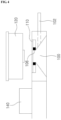
- FIG. 5 is a view showing the configuration of a confocal microscope system and arrangement of the lung window apparatus and the objective lens according to an embodiment.
- a process of obtaining an image according to the embodiment is as follows.
- a fluorescent signal excited in the lung tissue is detected through a detector.
- the confocal microscopic system includes four laser sources 500-1 to 500-4 respectively four wavelengths of 405nm, 488nm, 561nm, and 640nm within the visible light band, a polygonal rotation mirror 502, and a galvanometer mirror 504, and generates an XY raster scanning pattern, using these components.
- the confocal microscopic system may comprise a plurality of neutral density filters ND, mirrors M, and Dichroic beam splitters DBS, and beam pass filters BPF and photomultiplier tubes for detecting a fluorescent signal excited in a lung tissue.
- An optical system was designed to have an observation view of 250 ⁇ 250 ⁇ m 2 at the focus when using a ⁇ 40 objective lens (LUCPlanFL, NA0.6; Olympus) and a fluorescent signal was detected and processed by photomultiplier tubes individually and frame grabbers (Matrox, SOLIOS) that are provided for wavelengths such that 2D images having cellular-level resolution and being able to be sectioned in the Z-axial direction could be obtained at a speed of 30 sheets per second.
- the lung window apparatus By attaching the lung window apparatus according to an embodiment to the confocal microscope system and radiating laser beams to a lung tissue through an objective lens, it is possible to obtaining cellular-level images in real time through excited fluorescent signals.
- FIG. 6 is a view showing a lung tissue image obtained using a microaspiration-based lung window apparatus and a confocal microscope system according to an embodiment.
- a lung tissue has a pulmonary alveolus and a capillary vessel surrounding the pulmonary alveolus and the capillary vessel has a vascular endothelial cell and a basement membrane covering the vascular endothelial cell.
- a black circular pulmonary alveoli and a capillary vessel (green in FIG. 6A and red in FIG. 6B ) composed of vascular endothelial cells surrounding the lungs are found.
- nuclei green in FIG. 6B .
- type I pulmonary cells type II pulmonary alveoli
- nuclei of macrophages around the pulmonary cells could be found.
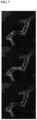
- FIG. 7 is a view showing an image obtained by continuously imaging movement of erythrocyte after injecting FITC-Dextran into a C57BL6/J mouse obtained using a microaspiration-based lung window apparatus and a confocal microscope system according to an embodiment.
- An image for observing movement of erythrocyte and leukocyte was checked in consideration of influence on cells in a lung tissue due to microaspiration.
- An image of erythrocyte contrasted by black was obtained by injecting FITC-Dextran into a blood vessel of the C57BL6/J mouse, and as in FIG. 7 , it was found that movement of the erythrocyte was continued and was not influenced by microaspiration.
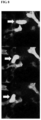
- FIG. 8 is a view showing an image obtained by continuously imaging movement of leukocyte in the LysM-GFP mouse obtained using a microaspiration-based lung window apparatus and a confocal microscope system according to an embodiment.
- the apparatus was useful for low-invasive and microscopic access to a lung tissue of an animal model without interfering with physiological circulation. Further, it was found that the apparatus was suitable for securing stable images of lung parenchyma and blood vessels and obtaining images for finding out interaction of cells and single cellular-level movement.
Landscapes
- Health & Medical Sciences (AREA)
- Life Sciences & Earth Sciences (AREA)
- Physics & Mathematics (AREA)
- Engineering & Computer Science (AREA)
- General Health & Medical Sciences (AREA)
- Surgery (AREA)
- Pathology (AREA)
- Public Health (AREA)
- Biomedical Technology (AREA)
- Heart & Thoracic Surgery (AREA)
- Medical Informatics (AREA)
- Molecular Biology (AREA)
- Veterinary Medicine (AREA)
- Animal Behavior & Ethology (AREA)
- Biophysics (AREA)
- Chemical & Material Sciences (AREA)
- Analytical Chemistry (AREA)
- General Physics & Mathematics (AREA)
- Optics & Photonics (AREA)
- Physiology (AREA)
- Pulmonology (AREA)
- Multimedia (AREA)
- Microscoopes, Condenser (AREA)
- Nuclear Medicine, Radiotherapy & Molecular Imaging (AREA)
- Radiology & Medical Imaging (AREA)
- Investigating, Analyzing Materials By Fluorescence Or Luminescence (AREA)
Claims (3)
- Appareil à fenêtre pulmonaire basé sur la micro-aspiration destiné à une utilisation avec un microscope optique confocal pour obtenir une image microscopique d'un tissu pulmonaire, l'appareil comprenant :une fenêtre ouverte (100) conçue pour s'ouvrir dans des parties supérieures et inférieures de celle-ci, avoir un verre de protection (110) placé sur sa partie supérieure, et avoir un tissu pulmonaire mis en contact avec sa partie inférieure ;un tube d'aspiration (102) conçu pour s'étendre jusqu'à un dispositif d'aspiration à partir d'un côté de la fenêtre ouverte (100) et faire le vide à l'intérieur de la fenêtre ouverte (100) ;caractérisé en ce que l'appareil comprend en outre :un siège à montage inclinable (104), conçu pour s'étendre à partir d'un côté de la fenêtre ouverte (100), où un montage inclinable (140) est placé pour ajuster l'angle de l'appareil à fenêtre pulmonaire, de sorte que, dans le cas où un système de microscope confocal et ses lentilles d'objectif (120) sont connectés à l'appareil à fenêtre pulmonaire basé sur la micro-aspiration, le verre de protection (110) et une lentille d'objectif (120) d'un système de microscope confocal sont maintenus parallèles,dans lequel la fenêtre ouverte (100) et le tube d'aspiration (102) sont formés dans un premier plateau (200) qui a un premier corps (210) et des premières protubérances (212) faisant une marche par rapport au premier corps (210) et faisant saillie à partir de côtés du premier corps (210), et le siège à montage inclinable (104) est formé dans un second plateau (202) qui a un second corps (220) et des secondes protubérances (222) faisant une marche par rapport au second corps (220) et se joignant aux premières protubérances (212).
- Appareil selon la revendication 1, dans lequel la fenêtre ouverte (100) possède une forme conique dont un diamètre est augmenté à partir de sa partie supérieure vers sa partie inférieure.
- Appareil selon la revendication 1, dans lequel le siège à montage inclinable (104) possède une pluralité de trous de fixation (130) pour se coupler au montage inclinable (140).
Applications Claiming Priority (2)
| Application Number | Priority Date | Filing Date | Title |
|---|---|---|---|
| KR1020150123216A KR101743283B1 (ko) | 2015-08-31 | 2015-08-31 | 생체 내 폐조직 미세영상 획득을 위한 미세흡인 기반 폐 윈도우 장치 및 이를 이용한 영상 획득 방법 |
| PCT/KR2016/009720 WO2017039316A1 (fr) | 2015-08-31 | 2016-08-31 | Appareil à fenêtre pulmonaire basé sur la microaspiration pour l'obtention d'une image microscopique in vivo de tissu pulmonaire et procédé pour obtenir des images en utilisant l'appareil |
Publications (4)
| Publication Number | Publication Date |
|---|---|
| EP3345546A1 EP3345546A1 (fr) | 2018-07-11 |
| EP3345546A4 EP3345546A4 (fr) | 2019-05-29 |
| EP3345546B1 true EP3345546B1 (fr) | 2023-10-04 |
| EP3345546C0 EP3345546C0 (fr) | 2023-10-04 |
Family
ID=58188002
Family Applications (1)
| Application Number | Title | Priority Date | Filing Date |
|---|---|---|---|
| EP16842282.2A Active EP3345546B1 (fr) | 2015-08-31 | 2016-08-31 | Appareil à fenêtre pulmonaire basé sur la microaspiration pour l'obtention d'une image microscopique in vivo de tissu pulmonaire |
Country Status (6)
| Country | Link |
|---|---|
| US (1) | US10437035B2 (fr) |
| EP (1) | EP3345546B1 (fr) |
| JP (1) | JP6630831B2 (fr) |
| KR (1) | KR101743283B1 (fr) |
| CN (1) | CN108601555B (fr) |
| WO (1) | WO2017039316A1 (fr) |
Families Citing this family (2)
| Publication number | Priority date | Publication date | Assignee | Title |
|---|---|---|---|---|
| HK1254295A1 (zh) | 2015-11-23 | 2019-07-19 | 默克专利股份有限公司 | 用於治疗纤维化和/或纤维化病症的抗-αV整合素抗体 |
| CN109030438A (zh) * | 2018-07-06 | 2018-12-18 | 广州蓝勃生物科技有限公司 | 一种用于多波长荧光检测的光路模组 |
Family Cites Families (26)
| Publication number | Priority date | Publication date | Assignee | Title |
|---|---|---|---|---|
| JPS5421752A (en) * | 1977-07-19 | 1979-02-19 | Toshiba Corp | Stage device for microscopes |
| JP3214805B2 (ja) * | 1995-07-17 | 2001-10-02 | シャープ株式会社 | 対物レンズ調整機構 |
| US5907425A (en) * | 1995-12-19 | 1999-05-25 | The Board Of Trustees Of The Leland Stanford Junior University | Miniature scanning confocal microscope |
| WO2000049392A1 (fr) * | 1999-02-17 | 2000-08-24 | Lucid, Inc. | Cassette destinee a faciliter le sectionnement optique d'un prelevement de tissu retenu |
| US20060100666A1 (en) * | 2000-04-20 | 2006-05-11 | Pulmosonix Pty. Ltd. | Apparatus and method for lung analysis |
| US6414779B1 (en) * | 2000-11-30 | 2002-07-02 | Opeical Biopsy Technologies, Inc. | Integrated angled-dual-axis confocal scanning endoscopes |
| US6898006B2 (en) * | 2001-12-26 | 2005-05-24 | Olympus Optical Co., Ltd. | Microscope |
| CN1439878A (zh) * | 2003-01-17 | 2003-09-03 | 陕西超英生物医学研究开发有限公司 | 自身抗体检测组织芯片 |
| CN1253716C (zh) * | 2004-01-08 | 2006-04-26 | 中南大学湘雅医学院肿瘤研究所 | 一种用于肿瘤早期诊断的组织芯片及制备器具 |
| EP1748724A1 (fr) | 2004-05-11 | 2007-02-07 | Koninklijke Philips Electronics N.V. | Tete de mesure destinee a l'analyse non invasive de sang |
| US7945077B2 (en) * | 2005-11-30 | 2011-05-17 | Lawrence Livermore National Security, Llc | Hyperspectral microscope for in vivo imaging of microstructures and cells in tissues |
| JP5268282B2 (ja) * | 2007-05-15 | 2013-08-21 | 有限会社 楠屋 | 個体内部の組織学的イメージ像を観察・取得する方法 |
| JP4996977B2 (ja) * | 2007-05-25 | 2012-08-08 | オリンパス株式会社 | スタビライザおよび生体観察装置 |
| US7906076B2 (en) * | 2007-07-02 | 2011-03-15 | University Of Massachusetts | Method and apparatus for biopsy sample processing |
| US8206315B2 (en) * | 2008-09-30 | 2012-06-26 | Suros Surgical Systems, Inc. | Real-time pathology |
| KR101042505B1 (ko) * | 2008-11-27 | 2011-06-16 | 현대제철 주식회사 | 주사 전자 현미경의 시편 홀더장치 |
| CN101872064B (zh) * | 2009-04-24 | 2012-07-04 | 陈亮嘉 | 线型多波长共焦显微镜模块以及其共焦显微方法与系统 |
| CN102297873A (zh) * | 2011-05-03 | 2011-12-28 | 杭州一二八医院 | 利用软x射线显微成像进行癌细胞图形识别的方法 |
| CN202075487U (zh) * | 2011-06-03 | 2011-12-14 | 江南大学 | 自平行读数显微镜 |
| JP5930364B2 (ja) * | 2011-11-28 | 2016-06-08 | 国立大学法人京都大学 | 生体試料固定器 |
| WO2013109624A2 (fr) * | 2012-01-17 | 2013-07-25 | Mayo Foundation For Medical Education And Research | Endomicroscopie confocale à balayage laser par sonde |
| JP6037732B2 (ja) * | 2012-09-03 | 2016-12-07 | オリンパス株式会社 | 浸液保持具、観察部位固定装置、及び、顕微鏡 |
| CN103202696B (zh) * | 2013-03-06 | 2014-12-17 | 王胜昱 | 基于气溶胶呼出气检测肺部疾病的建模方法 |
| US10007102B2 (en) * | 2013-12-23 | 2018-06-26 | Sakura Finetek U.S.A., Inc. | Microscope with slide clamping assembly |
| US20160095532A1 (en) * | 2014-10-03 | 2016-04-07 | Weinberg Medical Physics Llc | Method and components for in vivo determination of malignancy |
| WO2016200985A1 (fr) * | 2015-06-08 | 2016-12-15 | Trustees Of Tufts College | Système d'imagerie pour caractériser des changements dynamiques dans la cellule et des caractéristiques de particules |
-
2015
- 2015-08-31 KR KR1020150123216A patent/KR101743283B1/ko active Active
-
2016
- 2016-08-31 CN CN201680062597.XA patent/CN108601555B/zh active Active
- 2016-08-31 US US15/756,478 patent/US10437035B2/en active Active
- 2016-08-31 JP JP2018530459A patent/JP6630831B2/ja active Active
- 2016-08-31 EP EP16842282.2A patent/EP3345546B1/fr active Active
- 2016-08-31 WO PCT/KR2016/009720 patent/WO2017039316A1/fr not_active Ceased
Also Published As
| Publication number | Publication date |
|---|---|
| KR20170025998A (ko) | 2017-03-08 |
| EP3345546A4 (fr) | 2019-05-29 |
| CN108601555B (zh) | 2021-01-29 |
| CN108601555A (zh) | 2018-09-28 |
| JP2018526688A (ja) | 2018-09-13 |
| EP3345546C0 (fr) | 2023-10-04 |
| WO2017039316A8 (fr) | 2018-03-22 |
| US10437035B2 (en) | 2019-10-08 |
| KR101743283B1 (ko) | 2017-06-02 |
| JP6630831B2 (ja) | 2020-01-15 |
| WO2017039316A1 (fr) | 2017-03-09 |
| US20180246311A1 (en) | 2018-08-30 |
| EP3345546A1 (fr) | 2018-07-11 |
Similar Documents
| Publication | Publication Date | Title |
|---|---|---|
| US10314490B2 (en) | Method and device for multi-spectral photonic imaging | |
| JP5052019B2 (ja) | 医用画像化システム | |
| EP2770899B1 (fr) | Imagerie tissulaire et cellulaire | |
| JP2013078592A (ja) | 生物組織の機能的能力の変化を非破壊的に測定する方法 | |
| KR101898220B1 (ko) | 공초점 현미경 및 이를 이용한 영상 처리 방법 | |
| JPH0614921B2 (ja) | 生体組織螢光観察装置 | |
| CN116830007A (zh) | 用于实时采集活体体积的体积组织学图像的护理点显微镜 | |
| EP3345546B1 (fr) | Appareil à fenêtre pulmonaire basé sur la microaspiration pour l'obtention d'une image microscopique in vivo de tissu pulmonaire | |
| US6600943B1 (en) | Method for detecting a specific portion of organism specimen, method for physiological measurement of organism specimen, apparatus for detecting a specific portion of organism specimen, and a device for holding optical fiber | |
| US20080253968A1 (en) | In vivo examination method | |
| KR102186327B1 (ko) | 생체 심부 조직의 미세 영상 획득 시스템 및 이의 미세 영상 제공 방법 | |
| JP2003010189A (ja) | 生体機能情報撮像装置 | |
| JP6670385B2 (ja) | 生体内乳房組織の顕微鏡イメージ取得のためのウィンドー装置及びこれを利用したイメージ取得方法 | |
| KR101767339B1 (ko) | 생체 내 췌장조직 미세영상 획득을 위한 윈도우 장치 및 이를 이용한 영상 획득 방법 | |
| JP2011101763A (ja) | 画像表示装置 | |
| CN213821376U (zh) | 供微循环监测使用的口塞结构及连续微循环监测装置 | |
| KR20190079187A (ko) | 다중 모달 융합 내시경 시스템 | |
| JP6722620B2 (ja) | 細胞状態の解析装置および解析方法 | |
| Jones et al. | In vivo multiphoton microscopy of cardiomyocyte calcium dynamics in the beating mouse heart | |
| JPH05115467A (ja) | 代謝情報測定装置 | |
| Taruttis et al. | Fast deep-tissue multispectral optoacoustic tomography (MSOT) for preclinical imaging of cancer and cardiovascular disease | |
| Provaznik et al. | Fibre optic sensor for recording of action potentials |
Legal Events
| Date | Code | Title | Description |
|---|---|---|---|
| STAA | Information on the status of an ep patent application or granted ep patent |
Free format text: STATUS: THE INTERNATIONAL PUBLICATION HAS BEEN MADE |
|
| PUAI | Public reference made under article 153(3) epc to a published international application that has entered the european phase |
Free format text: ORIGINAL CODE: 0009012 |
|
| STAA | Information on the status of an ep patent application or granted ep patent |
Free format text: STATUS: REQUEST FOR EXAMINATION WAS MADE |
|
| 17P | Request for examination filed |
Effective date: 20180312 |
|
| AK | Designated contracting states |
Kind code of ref document: A1 Designated state(s): AL AT BE BG CH CY CZ DE DK EE ES FI FR GB GR HR HU IE IS IT LI LT LU LV MC MK MT NL NO PL PT RO RS SE SI SK SM TR |
|
| AX | Request for extension of the european patent |
Extension state: BA ME |
|
| DAV | Request for validation of the european patent (deleted) | ||
| DAX | Request for extension of the european patent (deleted) | ||
| A4 | Supplementary search report drawn up and despatched |
Effective date: 20190502 |
|
| RIC1 | Information provided on ipc code assigned before grant |
Ipc: A61B 5/00 20060101ALI20190425BHEP Ipc: G02B 21/00 20060101ALI20190425BHEP Ipc: A61B 5/08 20060101AFI20190425BHEP Ipc: G02B 21/36 20060101ALI20190425BHEP |
|
| STAA | Information on the status of an ep patent application or granted ep patent |
Free format text: STATUS: EXAMINATION IS IN PROGRESS |
|
| 17Q | First examination report despatched |
Effective date: 20220517 |
|
| GRAP | Despatch of communication of intention to grant a patent |
Free format text: ORIGINAL CODE: EPIDOSNIGR1 |
|
| STAA | Information on the status of an ep patent application or granted ep patent |
Free format text: STATUS: GRANT OF PATENT IS INTENDED |
|
| INTG | Intention to grant announced |
Effective date: 20230419 |
|
| GRAS | Grant fee paid |
Free format text: ORIGINAL CODE: EPIDOSNIGR3 |
|
| GRAA | (expected) grant |
Free format text: ORIGINAL CODE: 0009210 |
|
| STAA | Information on the status of an ep patent application or granted ep patent |
Free format text: STATUS: THE PATENT HAS BEEN GRANTED |
|
| AK | Designated contracting states |
Kind code of ref document: B1 Designated state(s): AL AT BE BG CH CY CZ DE DK EE ES FI FR GB GR HR HU IE IS IT LI LT LU LV MC MK MT NL NO PL PT RO RS SE SI SK SM TR |
|
| REG | Reference to a national code |
Ref country code: GB Ref legal event code: FG4D |
|
| REG | Reference to a national code |
Ref country code: CH Ref legal event code: EP |
|
| REG | Reference to a national code |
Ref country code: IE Ref legal event code: FG4D |
|
| REG | Reference to a national code |
Ref country code: DE Ref legal event code: R096 Ref document number: 602016083257 Country of ref document: DE |
|
| U01 | Request for unitary effect filed |
Effective date: 20231012 |
|
| U07 | Unitary effect registered |
Designated state(s): AT BE BG DE DK EE FI FR IT LT LU LV MT NL PT SE SI Effective date: 20231023 |
|
| PG25 | Lapsed in a contracting state [announced via postgrant information from national office to epo] |
Ref country code: GR Free format text: LAPSE BECAUSE OF FAILURE TO SUBMIT A TRANSLATION OF THE DESCRIPTION OR TO PAY THE FEE WITHIN THE PRESCRIBED TIME-LIMIT Effective date: 20240105 |
|
| PG25 | Lapsed in a contracting state [announced via postgrant information from national office to epo] |
Ref country code: IS Free format text: LAPSE BECAUSE OF FAILURE TO SUBMIT A TRANSLATION OF THE DESCRIPTION OR TO PAY THE FEE WITHIN THE PRESCRIBED TIME-LIMIT Effective date: 20240204 |
|
| PG25 | Lapsed in a contracting state [announced via postgrant information from national office to epo] |
Ref country code: ES Free format text: LAPSE BECAUSE OF FAILURE TO SUBMIT A TRANSLATION OF THE DESCRIPTION OR TO PAY THE FEE WITHIN THE PRESCRIBED TIME-LIMIT Effective date: 20231004 |
|
| PG25 | Lapsed in a contracting state [announced via postgrant information from national office to epo] |
Ref country code: IS Free format text: LAPSE BECAUSE OF FAILURE TO SUBMIT A TRANSLATION OF THE DESCRIPTION OR TO PAY THE FEE WITHIN THE PRESCRIBED TIME-LIMIT Effective date: 20240204 Ref country code: GR Free format text: LAPSE BECAUSE OF FAILURE TO SUBMIT A TRANSLATION OF THE DESCRIPTION OR TO PAY THE FEE WITHIN THE PRESCRIBED TIME-LIMIT Effective date: 20240105 Ref country code: ES Free format text: LAPSE BECAUSE OF FAILURE TO SUBMIT A TRANSLATION OF THE DESCRIPTION OR TO PAY THE FEE WITHIN THE PRESCRIBED TIME-LIMIT Effective date: 20231004 |
|
| PG25 | Lapsed in a contracting state [announced via postgrant information from national office to epo] |
Ref country code: RS Free format text: LAPSE BECAUSE OF FAILURE TO SUBMIT A TRANSLATION OF THE DESCRIPTION OR TO PAY THE FEE WITHIN THE PRESCRIBED TIME-LIMIT Effective date: 20231004 Ref country code: PL Free format text: LAPSE BECAUSE OF FAILURE TO SUBMIT A TRANSLATION OF THE DESCRIPTION OR TO PAY THE FEE WITHIN THE PRESCRIBED TIME-LIMIT Effective date: 20231004 Ref country code: NO Free format text: LAPSE BECAUSE OF FAILURE TO SUBMIT A TRANSLATION OF THE DESCRIPTION OR TO PAY THE FEE WITHIN THE PRESCRIBED TIME-LIMIT Effective date: 20240104 Ref country code: HR Free format text: LAPSE BECAUSE OF FAILURE TO SUBMIT A TRANSLATION OF THE DESCRIPTION OR TO PAY THE FEE WITHIN THE PRESCRIBED TIME-LIMIT Effective date: 20231004 |
|
| REG | Reference to a national code |
Ref country code: DE Ref legal event code: R097 Ref document number: 602016083257 Country of ref document: DE |
|
| PG25 | Lapsed in a contracting state [announced via postgrant information from national office to epo] |
Ref country code: CZ Free format text: LAPSE BECAUSE OF FAILURE TO SUBMIT A TRANSLATION OF THE DESCRIPTION OR TO PAY THE FEE WITHIN THE PRESCRIBED TIME-LIMIT Effective date: 20231004 |
|
| PG25 | Lapsed in a contracting state [announced via postgrant information from national office to epo] |
Ref country code: SK Free format text: LAPSE BECAUSE OF FAILURE TO SUBMIT A TRANSLATION OF THE DESCRIPTION OR TO PAY THE FEE WITHIN THE PRESCRIBED TIME-LIMIT Effective date: 20231004 |
|
| PG25 | Lapsed in a contracting state [announced via postgrant information from national office to epo] |
Ref country code: SM Free format text: LAPSE BECAUSE OF FAILURE TO SUBMIT A TRANSLATION OF THE DESCRIPTION OR TO PAY THE FEE WITHIN THE PRESCRIBED TIME-LIMIT Effective date: 20231004 Ref country code: SK Free format text: LAPSE BECAUSE OF FAILURE TO SUBMIT A TRANSLATION OF THE DESCRIPTION OR TO PAY THE FEE WITHIN THE PRESCRIBED TIME-LIMIT Effective date: 20231004 Ref country code: RO Free format text: LAPSE BECAUSE OF FAILURE TO SUBMIT A TRANSLATION OF THE DESCRIPTION OR TO PAY THE FEE WITHIN THE PRESCRIBED TIME-LIMIT Effective date: 20231004 Ref country code: CZ Free format text: LAPSE BECAUSE OF FAILURE TO SUBMIT A TRANSLATION OF THE DESCRIPTION OR TO PAY THE FEE WITHIN THE PRESCRIBED TIME-LIMIT Effective date: 20231004 |
|
| PLBE | No opposition filed within time limit |
Free format text: ORIGINAL CODE: 0009261 |
|
| STAA | Information on the status of an ep patent application or granted ep patent |
Free format text: STATUS: NO OPPOSITION FILED WITHIN TIME LIMIT |
|
| 26N | No opposition filed |
Effective date: 20240705 |
|
| U20 | Renewal fee for the european patent with unitary effect paid |
Year of fee payment: 9 Effective date: 20240829 |
|
| PG25 | Lapsed in a contracting state [announced via postgrant information from national office to epo] |
Ref country code: MC Free format text: LAPSE BECAUSE OF FAILURE TO SUBMIT A TRANSLATION OF THE DESCRIPTION OR TO PAY THE FEE WITHIN THE PRESCRIBED TIME-LIMIT Effective date: 20231004 |
|
| PG25 | Lapsed in a contracting state [announced via postgrant information from national office to epo] |
Ref country code: IE Free format text: LAPSE BECAUSE OF NON-PAYMENT OF DUE FEES Effective date: 20240831 |
|
| U20 | Renewal fee for the european patent with unitary effect paid |
Year of fee payment: 10 Effective date: 20250709 |
|
| PGFP | Annual fee paid to national office [announced via postgrant information from national office to epo] |
Ref country code: GB Payment date: 20250703 Year of fee payment: 10 |
|
| PGFP | Annual fee paid to national office [announced via postgrant information from national office to epo] |
Ref country code: CH Payment date: 20250901 Year of fee payment: 10 |
|
| PG25 | Lapsed in a contracting state [announced via postgrant information from national office to epo] |
Ref country code: CY Free format text: LAPSE BECAUSE OF FAILURE TO SUBMIT A TRANSLATION OF THE DESCRIPTION OR TO PAY THE FEE WITHIN THE PRESCRIBED TIME-LIMIT; INVALID AB INITIO Effective date: 20160831 |
|
| PG25 | Lapsed in a contracting state [announced via postgrant information from national office to epo] |
Ref country code: HU Free format text: LAPSE BECAUSE OF FAILURE TO SUBMIT A TRANSLATION OF THE DESCRIPTION OR TO PAY THE FEE WITHIN THE PRESCRIBED TIME-LIMIT; INVALID AB INITIO Effective date: 20160831 |