EP3345578A1 - Rétracteur médical pouvant être éclairé - Google Patents
Rétracteur médical pouvant être éclairé Download PDFInfo
- Publication number
- EP3345578A1 EP3345578A1 EP18000090.3A EP18000090A EP3345578A1 EP 3345578 A1 EP3345578 A1 EP 3345578A1 EP 18000090 A EP18000090 A EP 18000090A EP 3345578 A1 EP3345578 A1 EP 3345578A1
- Authority
- EP
- European Patent Office
- Prior art keywords
- hook
- handle portion
- light
- cavity
- medical
- Prior art date
- Legal status (The legal status is an assumption and is not a legal conclusion. Google has not performed a legal analysis and makes no representation as to the accuracy of the status listed.)
- Withdrawn
Links
Images

Classifications
-
- A—HUMAN NECESSITIES
- A61—MEDICAL OR VETERINARY SCIENCE; HYGIENE
- A61B—DIAGNOSIS; SURGERY; IDENTIFICATION
- A61B17/00—Surgical instruments, devices or methods
- A61B17/02—Surgical instruments, devices or methods for holding wounds open, e.g. retractors; Tractors
-
- A—HUMAN NECESSITIES
- A61—MEDICAL OR VETERINARY SCIENCE; HYGIENE
- A61B—DIAGNOSIS; SURGERY; IDENTIFICATION
- A61B90/00—Instruments, implements or accessories specially adapted for surgery or diagnosis and not covered by any of the groups A61B1/00 - A61B50/00, e.g. for luxation treatment or for protecting wound edges
- A61B90/30—Devices for illuminating a surgical field, the devices having an interrelation with other surgical devices or with a surgical procedure
-
- A—HUMAN NECESSITIES
- A61—MEDICAL OR VETERINARY SCIENCE; HYGIENE
- A61B—DIAGNOSIS; SURGERY; IDENTIFICATION
- A61B17/00—Surgical instruments, devices or methods
- A61B2017/0023—Surgical instruments, devices or methods disposable
-
- A—HUMAN NECESSITIES
- A61—MEDICAL OR VETERINARY SCIENCE; HYGIENE
- A61B—DIAGNOSIS; SURGERY; IDENTIFICATION
- A61B17/00—Surgical instruments, devices or methods
- A61B2017/00681—Aspects not otherwise provided for
- A61B2017/00734—Aspects not otherwise provided for battery operated
-
- A—HUMAN NECESSITIES
- A61—MEDICAL OR VETERINARY SCIENCE; HYGIENE
- A61B—DIAGNOSIS; SURGERY; IDENTIFICATION
- A61B90/00—Instruments, implements or accessories specially adapted for surgery or diagnosis and not covered by any of the groups A61B1/00 - A61B50/00, e.g. for luxation treatment or for protecting wound edges
- A61B90/03—Automatic limiting or abutting means, e.g. for safety
- A61B2090/037—Automatic limiting or abutting means, e.g. for safety with a frangible part, e.g. by reduced diameter
-
- A—HUMAN NECESSITIES
- A61—MEDICAL OR VETERINARY SCIENCE; HYGIENE
- A61B—DIAGNOSIS; SURGERY; IDENTIFICATION
- A61B90/00—Instruments, implements or accessories specially adapted for surgery or diagnosis and not covered by any of the groups A61B1/00 - A61B50/00, e.g. for luxation treatment or for protecting wound edges
- A61B90/30—Devices for illuminating a surgical field, the devices having an interrelation with other surgical devices or with a surgical procedure
- A61B2090/306—Devices for illuminating a surgical field, the devices having an interrelation with other surgical devices or with a surgical procedure using optical fibres
Definitions
- the invention relates to an illuminated medical retractor and thus a medical retaining hook, with the help of which in surgical procedures the access to an operating field is kept open or made possible by tissue spreading.
- retractor In order to have as undisturbed access to a surgical field of interest, it is often necessary during surgical procedures to retain or spread over surrounding tissue by means of a retractor.
- the retractor is most often held by a specialist nurse in the surgical service (e.g., a surgical assistant, a surgical-technical assistant or a surgical nurse) or an assisting physician. If retractors must be kept permanently in a constant position, it is also known to attach them to a used operating table for the duration of a surgical procedure.
- a retractor is often formed as a substantially rectangular body made of stainless steel, one leg of which is flattened rounded, and the other leg is thickened as a substantially cylindrical handle is formed.
- a good illumination of the surgical field is of great importance. It is desirable over the entire surgical field homogeneous and shadow-free as possible lighting with high illuminance.
- surgical lights are used, which are mounted above a surgical table on a ceiling mount.
- WO 2012/045459 A1 is an illuminated retaining hook with a replaceable hook element made of a polycarbonate or polymethyl methacrylate plastic material high mechanical strength and high impact resistance known, which hook element is connected via a positive coupling with a front end of a handle.
- the handle is designed as a hollow body for receiving an energy store.
- a white light emitting diode and its supply circuit is used in the hook element facing the front end of the handle.
- a light guide strand is integrated, which has a curved cross-section and is formed in the region of its free light exit end tapered tapered tapered Lichtauskoppel arrangements, which ensures a point-like light emission.
- the hook element is provided as an exchangeable disposable element, so that a subsequent cleaning and sterilization is eliminated.
- the two-part design of the retaining hook is disadvantageous. Since the entire force must be transmitted via the coupling between the retaining hook and the handle, there is a risk that the handle detaches from the retaining hook during a surgical procedure and obstructs a treating physician. In addition, only a very small part of the surgical field can be irradiated. Furthermore, the handle must be sterilized after each use, which greatly reduces the life expectancy of the energy storage and the diode. In particular, the optical properties of a light exit surface of the handle can be attacked during sterilization, so that with increasing useful life less and less light can be coupled into the light guide strand of the hook element.
- Embodiments of a medical retractor include a handle portion and a hook portion.
- the handle portion is at least partially formed as a hollow body having a cavity.
- the handle portion completely along its longitudinal direction (direction of its largest extension) as a hollow body be educated.
- a cavity of the limiting wall of the handle portion may have a constant thickness over the entire extent of the hollow body.
- the hook section has at least one light guide with a light entry surface and a light exit surface.
- the handle portion, the hook portion and the light guide are integrally formed and thus permanently connected rigidly. The handle portion, the hook portion and the light guide can not be separated from each other without destroying each other.
- the light entrance surface of the at least one light guide is disposed in the cavity formed in the handle portion or disposed flush with an inner wall of the cavity formed in the handle portion.
- the light entry surface is oriented toward an interior of the cavity, so that light generated in the interior of the cavity can enter the light guide via the light entry surface.
- the light exit surface of the at least one light guide is oriented away from the handle portion.
- the light entry surface and light exit surface may, for example, be oriented in opposite directions or enclose an angle greater than 60 ° with each other.
- the optical fiber may extend straight or curved. In particular, he can follow a course of the holding hook at least in sections.
- the light guide has a cross section which is constant or increases in the region of the light exit surface towards the light exit surface.
- the cross section of the light guide can also be constant over the entire extension of the light guide from the light entry surface to the light exit surface or increase steadily.
- the handle portion, the hook portion and the light guide are integrally formed, eliminating a mounting of the light guide on the hook portion of the retractor. Furthermore, there is no danger of unintentional detachment of the light guide from the hook section. It is also possible to form the handle portion, the hook portion and the light guide so that no gaps remain between the handle portion, the hook portion and the light guide, which brings advantages in terms of hygiene advantages.
- the retractor can be designed as a disposable part.
- the cross section of the light guide in the area of the light exit surface towards the light exit surface is constant or increases, it comes to a leakage of light from the light guide not to a bundling, but to a scatter, whereby a comparatively large compared to the prior art surface of the surgical field illuminated can be.
- the hook portion of the retractor is often located in use very close to the surgical field.
- the region of the light exit surface is understood to mean the section of the light guide which extends from the light exit surface by at most 10% of the greatest longitudinal extension of the light guide to the light entry surface of the light guide.
- the handle portion is at least partially formed as a hollow body, it can be made sufficiently thick with little use of material in order to be well grasped can. Furthermore, it can absorb in its interior a light source and an energy source, which then no longer need to be sterilized.
- the retractor can be designed, for example, as a roux hook, a Langenbeck hook or a Fritsch hook.
- no joint is provided between the grip portion, the hook portion and the light guide.
- the light guide has at its light exit surface a diverging lens or a plane Surface on which is oriented perpendicular to a longitudinal direction (direction of greatest extent) of the light guide.
- the medical retractor further comprises a lid, which closes the cavity formed in the handle portion in particular liquid-tight and further in particular airtight.
- the lid can be designed, for example, as a screw cap, strap closure or bayonet closure, and have a separate seal, for example made of plastic. In this way it is possible to take in the cavity of the hollow body an unsterile body, and to shield against external influences. It is then sufficient if the retractor is sterile outside the cavity of the hollow body. This can easily be achieved, for example, by designing the retractor as a sterile disposable item which is individually packaged individually.
- At least one hook is formed on the grip section, which engages with the cover when the cover is closed, and the grip section has at least one predetermined breaking point which allows the closed cover to be opened by breaking off.
- the predetermined breaking point is formed on the hook.
- the predetermined breaking point is formed adjacent to a screw thread formed on the grip portion.
- the lid and the at least one hook are coordinated so that a secure closure of the lid is possible only when the hook is intact. In this way it can be ensured that a trained as a single part retractor can not be used again.
- the handle portion in the formed as a hollow body portion an opening which breaks through a cavity surrounding the hollow body wall, and this opening is liquid-tight and in particular hermetically sealed by a cover made of elastomer and in particular silicone.
- a cover made of elastomer and in particular silicone.
- the opening is arranged in the circumferential direction of the grip portion.
- the opening is arranged on an end face of the grip portion and thus in the longitudinal direction.
- the opening is arranged in a cover which closes off the cavity formed in the grip section.
- the grip section has on its surface at least one region which is formed of slip-resistant material and in particular elastomer and is connected in a planar manner to the grip section. This is advantageous because retractors are often used in a humid environment and must be kept safely with gloves.
- one or more grip recesses or one or more friction-increasing, in particular rounded, protrusions are formed in the grip section.
- the gripping portion has a connection area which is designed to be fastened to a holding system of an operating table.
- the retractor does not need to be held continuously during a surgical procedure, but can be temporarily or continuously fixed.
- the connection area is thus integral with the handle portion formed, and formed of the same material as the handle portion.
- the handle portion has at least one plate-shaped projection, in which at least one fastening opening is formed, which forms the connection area together with the plate-shaped projection.
- connection region is designed in the form of a pair of plate-shaped projections, each having a fastening opening, wherein the plate-shaped projections lie in a common plane.
- the plate-shaped protrusions are arranged to face each other with respect to the grip portion, and the hook portion encloses the same angle with each of the plate-shaped protrusions.
- the at least one plate-shaped projection adjacent to the grip portion has a radius of between 0.8 cm and 1.5 cm.
- connection region is designed in the form of a coupling element which extends in a straight line parallel to the longitudinal extension of the grip section.
- the coupling element is arranged on the side of the grip portion which faces away from the hook portion.
- the coupling element has a trapezoidal cross-section.
- a plurality of coupling elements are provided, which lie opposite each other with respect to the handle portion.
- connection region is formed adjacent to the hook section on the grip section.
- the coupling element is a projection. According to an alternative embodiment, the coupling element is a recess.
- the handle portion and the hook portion and the light guide are formed of the same material.
- the retractor can be produced in a particularly simple and cost-effective manner by injection molding.
- the handle portion and the hook portion are formed of a first material
- the light conductor is formed of a second material different from the first material, which is coextruded together with the first material.
- the first material and the second material must be co-extrudable materials.
- the grip portion, the hook portion and the light guide thus form a coextrusion product.
- the use of different materials makes it possible to use for the light guide a material which has particularly good light-conducting properties, and to use for the grip portion and hook portion a material which is particularly stiff and / or break-resistant. By coextrusion, however, the production is still possible at low cost.
- the handle portion and the hook portion are formed from a plastic material
- the light guide is a from a different material of the plastic material and second quartz glass formed insert, which is permanently surface-connected by injection molding with plastic material with the plastic material.
- the optical fiber is partially or completely encapsulated with a plastic material.
- the use of different materials allows for the light guide to use a material which has particularly good light-conducting properties, and to use for the grip portion and hook portion a material which is particularly stiff and / or break-resistant. By overmolding a permanent and secure connection of the light guide with the hook part is possible. Furthermore, it is even possible to use a material for the light guide which splits in the event of overloading, since it can be avoided by splashing the light guide with the plastic material that splinters get into the surgical field.
- the light guide is formed from polymethylmethacrylate, polycarbonate, polyetheretherketone or quartz glass. These materials have a good photoconductive property, since total reflection can occur at interfaces.
- the grip portion and the hook portion are formed of polymethylmethacrylate, polyetheretherketone or polycarbonate. These materials have good heat resistance, optical clarity, high mechanical strength and impact resistance. In addition, these materials allow the production of the light guide and handle portion and hook portion of the same material.
- the cavity formed in the grip portion has an oval or polygonal inner cross section. This allows a twist-proof arrangement of a correspondingly shaped body in the cavity enclosed by the hollow body. If this shape is also found on the outside of the handle portion, the retractor can also be held against rotation.
- the cavity formed in the handle portion has a length of between 5 cm and 20 cm and in particular a length of between 7.5 cm and 15 cm.
- the cavity formed in the grip portion has a largest inner diameter of between 1 cm and 8 cm and in particular between 2 cm and 5 cm and more particularly 3 cm. If this dimensioning is found with a surcharge of at most one centimeter on the outside of the handle portion, the retractor can be conveniently held by the hands of a user.
- the light guide has a round or oval or rectangular or trapezoidal or triangular cross-section.
- a (main) extension direction of the grip portion and a (main) extension direction of the hook portion include an angle of between 60 ° and 180 °, and more preferably between 80 ° and 100 ° and more particularly 90 °.
- the hook portion has a length of between 1 cm to 40 cm and in particular of between 10 cm to 30 cm and more particularly of 20 cm.
- the hook portion has a width of between 0.5 cm to 10 cm and in particular of between 1.5 cm to 5 cm and more particularly of 4 cm.
- the light guide has a length which corresponds to between 50% and 100% and in particular between 60% and 90% of the length of the holding hook.
- the medical retractor further comprises one or more than one light source, which is arranged together with a power source, in particular a battery or a rechargeable battery, in a common housing, which housing has one or more than one light exit surface, which visually with the at least one light source is connected.
- the at least one light source accommodating housing is arranged so formed in the handle portion cavity that the at least one light exit surface of the housing is aligned towards the light entry surface of the at least one light guide.
- a shape and size of the housing receiving the at least one light source can be selected such that the housing comes to rest flat against an inner wall of the cavity formed in the grip section.
- the at least one light source may, for example, be a light-emitting diode LED and in particular a high-power LED or a laser diode.
- the use of a gas discharge or incandescent lamp is alternatively possible.
- At least one hook is formed in the interior of the cavity formed in the handle portion, which holds the housing receiving the light source inside the handle portion, when the housing housing the light source is disposed in the handle portion, wherein the hook has a predetermined breaking point, which by breaking the at least one retaining hook allows removal of the housing receiving the light source from the grip section.
- the retaining hook can elastically bias the light exit surface of the housing, for example, in the direction of the light entry surface of the light guide, and thus a good contact of the light exit surface of the housing at the light entry surface of the light guide. In this way it can be ensured that trained as disposable retractors can actually be used only once.
- the hook may be formed integrally with the handle portion.
- the light exit surface of the housing receiving the light source is designed to be complementary to the light entry surface of the at least one light guide. This allows a flat contact of the two surfaces to each other and a low-loss transfer guided light.
- the retractor further includes a switch, the switch being disposed between the power source and the light source and configured to selectively connect the light source to the power source. Switches are very inexpensive and reliable passive components.
- the retractor further comprises a controller and a switch, wherein the controller is connected to the power source, the switch and the light source and configured to control the light source as a result of actuation of the switch.
- the controller is connected to the power source, the switch and the light source and configured to control the light source as a result of actuation of the switch.
- the radiation power of the light source at reduced power corresponds to between 25% and 75% of the radiant power of the light source at maximum power.
- the grip portion has an opening in the region formed as a cavity, which breaks through a wall enclosing the cavity and is closed by a cover of elastomer and in particular silicone liquid-tight and in particular airtight. Then, the housing housing the light source is locatable in the cavity formed in the handle portion such that the switch is disposed adjacent to the opening. In this way, the switch can be operated via the cover of elastomer.
- the housing receiving the light source has an oval or polygonal outer cross section.
- the outer cross section may be formed complementary to an inner cross section of the cavity in the handle portion.
- projections for guiding the housing may be formed on the inner wall of the cavity in the interior of the handle portion. In this way it can be ensured that the housing receiving the light source can only be received correctly oriented by the cavity in the grip section.
- this includes the light source receiving housing has a length of between 5 cm and 20 cm and in particular a length of between 7.5 cm and 15 cm.
- the housing accommodating the light source has a maximum outside diameter of between 1 cm and 8 cm and in particular between 2 cm and 5 cm and more particularly 3 cm.
- At least the light exit surface of the at least one light guide has a nano-coating which leads a surface of the light exit surface to a superhydrophobic or superhydrophilic property.
- at least the entire hook portion has a nano-coating which gives a surface of the whole hook portion a superhydrophobic or super hydrophilic property. This makes it easier to keep the light exit surface free of contamination, so that the light guided in the light guide is attenuated as little as possible.
- At least the light exit surface of the at least one optical waveguide has a microstructured surface, which conveys a lotus effect to the surface of the light exit surface.
- at least the entire hook portion has a microstructured surface which gives the surface of the whole hook portion a lotus effect. This makes it easier to keep the light exit surface free of contamination, so that the light guided in the light guide is attenuated as little as possible.
- Embodiments of a lighting for a medical retractor have a light source, which together with an energy source, in particular a battery or a Accumulator, are arranged in a common housing, which housing has a light exit surface which is optically connected to the light source.
- the lighting comprises a controller and a switch, wherein the controller is connected to the power source, the switch and the light source and configured to control the light source as a result of actuation of the switch.
- the switch is designed as a button and in particular as a membrane key or sensor button.
- the controller is designed to switch the light source sequentially at least between the following operating states as a result of a repeated actuation of the probe: the light source is operated at reduced power; Light source is operated at maximum power; Light source is not operated.
- the radiant power of the light source at reduced power corresponds to between 25% and 75% of the radiant power of the light source at maximum power.
- the housing receiving the light source may have an oval or polygonal outer cross section.
- the housing accommodating the light source may have a length of between 5 cm and 20 cm and in particular a length of between 7.5 cm and 15 cm.
- the housing accommodating the light source may have a largest outer diameter of between 1 cm and 8 cm and in particular between 2 cm and 5 cm.
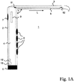
- FIGS. 1A to 1C a medical retractor 1 according to a first embodiment described.
- hidden elements are drawn with dashed lines.
- Fritsch hook medical retractor 1 has a handle portion 2 and a hook portion 3, the respective longitudinal extent (direction of greatest extent) together form an angle ⁇ of 90 °.
- the handle portion 2 is formed as a hollow body with an oval cross-section, and encloses a cavity 4 with also oval cross-section.
- the cavity 4 has a length of 15 cm, a maximum diameter of 3.5 cm and a smallest diameter of 3 cm.
- the cavity 4 limiting wall of the handle portion 2 has over the entire extent of the handle portion 2 has a constant thickness of 2 mm.
- the grip section 2 has two symmetrically formed connection regions 9 with bores 91 which project radially from the grip section and can be fastened to a holding system (not shown) of an operating table.
- the connection regions 9 are formed by plate-shaped projections into which the bores 91 are introduced.
- the plate-shaped projections are arranged in a plane, and are relative to the handle portion 2 opposite, as seen from Fig. 1C is apparent.
- the plate-shaped projections At its upper, the hook section 3 adjacent boundary edge, the plate-shaped projections each have a radius R1 of 1.5 cm.
- the plate-shaped projections are formed entirely without corners and thus rounded.
- the handle portion 2 has at its end facing away from the hook portion 3 on a designed as a snap cover 6, which closes the formed in the handle portion 2 cavity 4 liquid-tight and airtight.
- the cover 6 has a silicone O-ring (not shown).
- the handle section 2 At its side facing away from the hook section 3, the handle section 2 has an opening which breaks through the wall enclosing the cavity 4, and is liquid-tight and hermetically sealed by a cover made of silicone 7.
- a snap hook 15 is formed in the handle portion.
- the dimensioning of the snap hook is in Figure 1A heavily oversubscribed.
- the handle portion 2 has on its side facing the hook portion 3 on its surface four spaced apart in the longitudinal direction of the handle portion oval regions 8, which are formed of elastomer and flat connected to the handle portion 2.
- the hook portion 3 has a length of 20 cm and a width of 4 cm and a U-shaped cross section.
- the hook section 3 has a light guide 5 with a light entry surface 51 and a light exit surface 52, which follows a course of the hook section over 74% of its longitudinal extension.
- the light entrance surface 51 of the light guide 5 is arranged flush with an inner wall of the cavity 4 formed in the handle portion 2 and oriented toward an interior of the cavity 4.
- the light exit surface 52 of the light guide 5 is oriented in the opposite direction to the light entry surface 51 and thus away from the handle portion 2.
- the light guide 5 has a round cross-section with a Outside diameter D, which outer diameter D over the entire longitudinal extension L of the light guide 5, including the light entrance surface 51 and the light exit surface 52 is constant.
- the handle portion 2, the hook portion 3 and the light guide 5 are formed in this first embodiment as a one-piece injection molding of polymethyl methacrylate.
- the retractor 1 is formed so that no gaps between the handle portion 2, the hook portion 3 and the light guide 5 exist.
- the surface of the grip portion 2, the hook portion 3 and the light guide 5 are provided with a nano-coating which gives this surface a superhydrophobic property.
- the second embodiment differs from the embodiment described above in that the light guide 5 'is a quartz glass insert, which is encapsulated with polyether ether ketone except for its light entrance surface 51' and its light exit surface 52 ', from which the handle section 2 and the hook section 3 'are formed.
- the light entrance surface 51 'of the light guide 5' protrudes into the cavity 4 formed in the grip portion 2.
- optical waveguide 5 ' which in the second embodiment has a round cross-section, runs apart along its longitudinal direction L towards the light exit surface 52', so that its diameter increases continuously towards the light exit surface 52 '.
- a diverging lens is formed whose surface is so microstructured that a lotus effect (low wettability of the surface of the diverging lens, as can be observed in the lotus plant) occurs.
- An additional nano-coating of the grip section 2, the hook section 3 and the light guide 5 can then be dispensed with.
- a cover 6 designed as a screw cap.
- the handle portion 2 in the region of the lid 6 has a round cross-section.
- connection areas 9 are shown only cut.
- FIG. 2 an embodiment of an illumination, as it can be used in the medical retractors 1 described above.
- the lighting comprises a housing 10 made of opaque plastic, which receives a light source in the form of a white laser diode 11, a button 13 formed as a switch, a control circuit 14 and an energy source in the form of a battery 12.
- the laser diode 11 facing away from one end of the Housing 10 closed by a screw 16.
- the housing has a light exit surface in the form of a window 12 made of quartz glass, which is optically connected to a light outlet of the laser diode 11.
- the case has a slightly oval cross section, a length of 10 cm, a maximum outside diameter of 3.45 cm and a smallest outside diameter of 2.95 cm.
- the cross section of the housing 10 is well adapted to the cross section of the cavity 4 in the handle portion 2 of the medical retractor 1 described above.
- the housing 10 of the illumination is arranged in the cavity 4 formed in the handle portion 2, the window 12 in the housing 10 is aligned towards the light entrance surface 51 of the one light guide 5, and the probe 13 behind the cover 7 made of silicon Handle portion 2 is arranged. In this way, the switch on the cover 7 made of silicone 7 can be actuated.
- an outer surface of the window 12 is adapted to the light entry surface 51 and lies in flat in the cavity 4 of the handle portion 2 illumination at the light entrance surface 51 at.
- the housing 10 of the lighting is biased in arranged in the cavity 4 of the handle portion 2 lighting by the snap hook 15 in the direction of the chop section 3.
- the snap hook 15 has a predetermined breaking point 15 ', which allows removal of the lighting from the handle portion 2 by breaking off the snap hook 15.
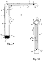
- FIGS. 3A and 3B A third embodiment of a medical retractor 1 is described. Since this embodiment is very similar to the first and second embodiments described above, only differences between these embodiments will be discussed, and otherwise referred to above.
- the third embodiment differs from the first and second embodiments described above in particular in that three light guides 5, 5 ', 5 "are provided, each with a light entrance surface 52, 52" and a light exit surface 51, 51'. For better clarity, not all light entry surfaces and light exit surfaces have been provided with reference numerals.
- the illumination used has a corresponding number of light sources in the form of high-power LEDs.
- the lighting is not shown in the figures, however, as it differs from the lighting of the FIG. 2 only differs by a second and third laser diode and an associated second and third windows.
- the third embodiment differs from the above-described first and second embodiments in that the terminal portion is formed in the form of three coupling members 9 ', 9 ", which are respectively extend rectilinearly parallel to the longitudinal extent of the handle portion and each having a trapezoidal cross-section.
- two coupling elements 9 ' are arranged so that they are relative to the handle portion 2 opposite.
- the third coupling element 9 "lies opposite the hook section 3.
- Two coupling elements 9 'are designed as projections, a coupling element 9" is formed as a recess.
- the third embodiment differs from the above-described first and second embodiments in that a hook 15 * is formed on the grip portion 2, which engages with the lid 6 when the lid 6 is closed.
- the handle portion 2 adjacent to this hook 15 * has a predetermined breaking point 15 ", which by breaking off allows the closed lid 6 to be opened.
- the predetermined breaking point 15" is both the hook 15 * and a thread (not shown) arranged adjacent to the lid 6.
- the third embodiment differs from the first and second embodiments described above in that a plurality of friction-increasing gripping depressions and projections 8 "are provided on the grip portion 2 instead of the elastomeric oval portions 8.
- the third embodiment differs from the first and second embodiments described above in that the switch 7 'is arranged on the end face of the grip section 2 facing away from the hook section 3 and thus in the cover 6.
Landscapes
- Health & Medical Sciences (AREA)
- Life Sciences & Earth Sciences (AREA)
- Surgery (AREA)
- Molecular Biology (AREA)
- General Health & Medical Sciences (AREA)
- Biomedical Technology (AREA)
- Heart & Thoracic Surgery (AREA)
- Medical Informatics (AREA)
- Nuclear Medicine, Radiotherapy & Molecular Imaging (AREA)
- Animal Behavior & Ethology (AREA)
- Engineering & Computer Science (AREA)
- Public Health (AREA)
- Veterinary Medicine (AREA)
- Oral & Maxillofacial Surgery (AREA)
- Pathology (AREA)
- Surgical Instruments (AREA)
- Dental Tools And Instruments Or Auxiliary Dental Instruments (AREA)
Applications Claiming Priority (3)
| Application Number | Priority Date | Filing Date | Title |
|---|---|---|---|
| DE102013021857.8A DE102013021857B4 (de) | 2013-12-26 | 2013-12-26 | Beleuchtbarer medizinischer Retraktor |
| PCT/EP2015/050017 WO2015097311A1 (fr) | 2013-12-26 | 2015-01-03 | Rétracteur médical pouvant être éclairé |
| EP15700642.0A EP3086743A1 (fr) | 2013-12-26 | 2015-01-03 | Rétracteur médical pouvant être éclairé |
Related Parent Applications (1)
| Application Number | Title | Priority Date | Filing Date |
|---|---|---|---|
| EP15700642.0A Division EP3086743A1 (fr) | 2013-12-26 | 2015-01-03 | Rétracteur médical pouvant être éclairé |
Publications (1)
| Publication Number | Publication Date |
|---|---|
| EP3345578A1 true EP3345578A1 (fr) | 2018-07-11 |
Family
ID=52391921
Family Applications (2)
| Application Number | Title | Priority Date | Filing Date |
|---|---|---|---|
| EP18000090.3A Withdrawn EP3345578A1 (fr) | 2013-12-26 | 2015-01-03 | Rétracteur médical pouvant être éclairé |
| EP15700642.0A Withdrawn EP3086743A1 (fr) | 2013-12-26 | 2015-01-03 | Rétracteur médical pouvant être éclairé |
Family Applications After (1)
| Application Number | Title | Priority Date | Filing Date |
|---|---|---|---|
| EP15700642.0A Withdrawn EP3086743A1 (fr) | 2013-12-26 | 2015-01-03 | Rétracteur médical pouvant être éclairé |
Country Status (3)
| Country | Link |
|---|---|
| EP (2) | EP3345578A1 (fr) |
| DE (1) | DE102013021857B4 (fr) |
| WO (1) | WO2015097311A1 (fr) |
Families Citing this family (2)
| Publication number | Priority date | Publication date | Assignee | Title |
|---|---|---|---|---|
| CN105997167B (zh) * | 2016-06-28 | 2019-01-01 | 杨璟辉 | 一种无需外接光源的导光拉钩 |
| DE102017204503A1 (de) | 2017-03-17 | 2018-09-20 | Schott Ag | Beleuchtungssystem mit flachem Leuchtabschnitt |
Citations (4)
| Publication number | Priority date | Publication date | Assignee | Title |
|---|---|---|---|---|
| US3638644A (en) * | 1969-03-05 | 1972-02-01 | Michael Elbert | Illuminated surgical speculum |
| DE202004001136U1 (de) * | 2004-01-08 | 2004-04-29 | Hidde, Gregor | Wundhaken mit Beleuchtung und Absaugung |
| DE202005019780U1 (de) * | 2005-01-12 | 2006-04-20 | Hidde, Gregor | Wundhaken mit Beleuchtung, Absaugung, Filter und auswechselbarem Wundhakenblatt |
| WO2012045459A1 (fr) * | 2010-10-07 | 2012-04-12 | Martina Heitland | Crochet de maintien médical avec éclairage |
Family Cites Families (8)
| Publication number | Priority date | Publication date | Assignee | Title |
|---|---|---|---|---|
| DE3367727D1 (en) * | 1982-07-30 | 1987-01-08 | Heraeus Gmbh W C | Retractor for surgical purposes |
| US7178941B2 (en) * | 2003-05-05 | 2007-02-20 | Color Kinetics Incorporated | Lighting methods and systems |
| US20070060795A1 (en) * | 2005-09-14 | 2007-03-15 | Spotlight Surgical, Inc. | Lighted surgical retractors with LED illumination light engines |
| US8409088B2 (en) * | 2006-01-18 | 2013-04-02 | Invuity, Inc. | Retractor illumination system |
| DE202007002593U1 (de) * | 2007-02-22 | 2007-04-19 | Aesculap Ag & Co. Kg | Endoskop für medizinische Zwecke |
| US20110013868A1 (en) * | 2007-12-17 | 2011-01-20 | Kouji Suzumura | Optical waveguide for visible light |
| DE202009017971U1 (de) * | 2009-06-19 | 2010-11-25 | Rudolf Storz Gmbh | Handgriff für ein chirurgisches Instrument sowie chirurgisches Instrument |
| DE102009030606A1 (de) * | 2009-06-23 | 2010-12-30 | Carl Zeiss Surgical Gmbh | Vorrichtung zum Offenhalten von Operationskanälen mit Innenbeleuchtung |
-
2013
- 2013-12-26 DE DE102013021857.8A patent/DE102013021857B4/de active Active
-
2015
- 2015-01-03 EP EP18000090.3A patent/EP3345578A1/fr not_active Withdrawn
- 2015-01-03 WO PCT/EP2015/050017 patent/WO2015097311A1/fr not_active Ceased
- 2015-01-03 EP EP15700642.0A patent/EP3086743A1/fr not_active Withdrawn
Patent Citations (4)
| Publication number | Priority date | Publication date | Assignee | Title |
|---|---|---|---|---|
| US3638644A (en) * | 1969-03-05 | 1972-02-01 | Michael Elbert | Illuminated surgical speculum |
| DE202004001136U1 (de) * | 2004-01-08 | 2004-04-29 | Hidde, Gregor | Wundhaken mit Beleuchtung und Absaugung |
| DE202005019780U1 (de) * | 2005-01-12 | 2006-04-20 | Hidde, Gregor | Wundhaken mit Beleuchtung, Absaugung, Filter und auswechselbarem Wundhakenblatt |
| WO2012045459A1 (fr) * | 2010-10-07 | 2012-04-12 | Martina Heitland | Crochet de maintien médical avec éclairage |
Also Published As
| Publication number | Publication date |
|---|---|
| EP3086743A1 (fr) | 2016-11-02 |
| DE102013021857A1 (de) | 2015-07-02 |
| DE102013021857B4 (de) | 2026-01-22 |
| WO2015097311A1 (fr) | 2015-07-02 |
Similar Documents
| Publication | Publication Date | Title |
|---|---|---|
| EP0349479B1 (fr) | Endoscope | |
| DE69022979T2 (de) | Starres video-endoskop mit durch hitze sterilisierbarer umhüllung. | |
| DE102012018170B4 (de) | Beleuchtungsvorrichtung für chirurgische Zwecke, Chirurgisches Instrument damit, Teil eines solchen Instruments sowie Set aus Beleuchtungsvorrichtung, chirurgischem Instrument und/oder Instrumententeil | |
| DE6929423U (de) | Laryngoskop. | |
| DE2636510B2 (de) | Endoskop, insbesondere Rektoskop, mit lösbarem, lichtleitendem Tubus | |
| DE102007049239A1 (de) | Endosonde | |
| DE102009056705A1 (de) | Uterusmanipulator | |
| EP2624766B1 (fr) | Crochet de maintien médical avec éclairage | |
| DE3023266A1 (de) | Wundhaken fuer chirurgische zwecke | |
| DE102012203118A1 (de) | Verbindungselement zum einmaligen Verbinden und einmaligen Lösen eines faseroptischen Lichtleiters mit bzw. von einer Lichtquelle | |
| DE102017100868A1 (de) | Endoskop mit einem Endoskop und einem am Endoskopkopf anbringbaren Albarranhebel | |
| EP2190355A2 (fr) | Dispositif pour l'entraînement d'instruments et d'outils, et son utilisation | |
| EP3570720B1 (fr) | Endoscope comprenant une tête d'endoscope et un levier d'albarran pouvant être agencé sur la tête d'endoscope et en être séparé | |
| EP3086743A1 (fr) | Rétracteur médical pouvant être éclairé | |
| DE102005002220A1 (de) | Wundhaken mit Beleuchtungseinrichtung und Absaugvorrichtung | |
| DE102010022403B4 (de) | Vorrichtung zum Einführen eines Mediums oder eines Instruments in den menschlichen Körper | |
| DE102017100865B4 (de) | Schutzkappe und Endoskop mit einer solchen Schutzkappe | |
| DE102014118575B4 (de) | Chirurgisches Instrument | |
| EP3373793B1 (fr) | Adaptateur stérile | |
| WO1988009192A1 (fr) | Revetement protecteur pour fibres optiques | |
| DE9215725U1 (de) | Vorrichtung zur Beleuchtung und Inspektion von Hohl- und Zwischenräumen | |
| DE10311198B4 (de) | Haltevorrichtung mit durchsichtigem Abdeckelement für Drape sowie Drape für ein Operationsmikroskop mit einer solchen Haltevorrichtung | |
| DE102011018688A1 (de) | Batterielichtquelle | |
| DE102005029639A1 (de) | Medizinisches, insbesondere zahnmedizinisches Instrument | |
| EP1481631A1 (fr) | Manche de laryngoscope |
Legal Events
| Date | Code | Title | Description |
|---|---|---|---|
| PUAI | Public reference made under article 153(3) epc to a published international application that has entered the european phase |
Free format text: ORIGINAL CODE: 0009012 |
|
| 17P | Request for examination filed |
Effective date: 20180228 |
|
| AC | Divisional application: reference to earlier application |
Ref document number: 3086743 Country of ref document: EP Kind code of ref document: P |
|
| AK | Designated contracting states |
Kind code of ref document: A1 Designated state(s): AL AT BE BG CH CY CZ DE DK EE ES FI FR GB GR HR HU IE IS IT LI LT LU LV MC MK MT NL NO PL PT RO RS SE SI SK SM TR |
|
| GRAP | Despatch of communication of intention to grant a patent |
Free format text: ORIGINAL CODE: EPIDOSNIGR1 |
|
| INTG | Intention to grant announced |
Effective date: 20190305 |
|
| STAA | Information on the status of an ep patent application or granted ep patent |
Free format text: STATUS: THE APPLICATION IS DEEMED TO BE WITHDRAWN |
|
| 18D | Application deemed to be withdrawn |
Effective date: 20190716 |