EP3345720A1 - Unité de séparation - Google Patents
Unité de séparation Download PDFInfo
- Publication number
- EP3345720A1 EP3345720A1 EP17206646.6A EP17206646A EP3345720A1 EP 3345720 A1 EP3345720 A1 EP 3345720A1 EP 17206646 A EP17206646 A EP 17206646A EP 3345720 A1 EP3345720 A1 EP 3345720A1
- Authority
- EP
- European Patent Office
- Prior art keywords
- joining element
- separation unit
- joining
- slide
- unit according
- Prior art date
- Legal status (The legal status is an assumption and is not a legal conclusion. Google has not performed a legal analysis and makes no representation as to the accuracy of the status listed.)
- Granted
Links
- 238000000926 separation method Methods 0.000 title claims abstract description 37
- 238000006073 displacement reaction Methods 0.000 claims abstract description 17
- 238000000576 coating method Methods 0.000 description 5
- 239000011248 coating agent Substances 0.000 description 4
- 238000000034 method Methods 0.000 description 3
- 230000002349 favourable effect Effects 0.000 description 2
- 230000005484 gravity Effects 0.000 description 2
- 239000000463 material Substances 0.000 description 2
- 239000007769 metal material Substances 0.000 description 2
- 239000000853 adhesive Substances 0.000 description 1
- 230000001070 adhesive effect Effects 0.000 description 1
- 230000002411 adverse Effects 0.000 description 1
- 239000003795 chemical substances by application Substances 0.000 description 1
- 238000010276 construction Methods 0.000 description 1
- 230000001419 dependent effect Effects 0.000 description 1
- 230000009977 dual effect Effects 0.000 description 1
- 239000002184 metal Substances 0.000 description 1
- 238000011144 upstream manufacturing Methods 0.000 description 1
- 238000003466 welding Methods 0.000 description 1
Images


Classifications
-
- B—PERFORMING OPERATIONS; TRANSPORTING
- B23—MACHINE TOOLS; METAL-WORKING NOT OTHERWISE PROVIDED FOR
- B23P—METAL-WORKING NOT OTHERWISE PROVIDED FOR; COMBINED OPERATIONS; UNIVERSAL MACHINE TOOLS
- B23P19/00—Machines for simply fitting together or separating metal parts or objects, or metal and non-metal parts, whether or not involving some deformation; Tools or devices therefor so far as not provided for in other classes
- B23P19/04—Machines for simply fitting together or separating metal parts or objects, or metal and non-metal parts, whether or not involving some deformation; Tools or devices therefor so far as not provided for in other classes for assembling or disassembling parts
- B23P19/06—Screw or nut setting or loosening machines
-
- B—PERFORMING OPERATIONS; TRANSPORTING
- B23—MACHINE TOOLS; METAL-WORKING NOT OTHERWISE PROVIDED FOR
- B23P—METAL-WORKING NOT OTHERWISE PROVIDED FOR; COMBINED OPERATIONS; UNIVERSAL MACHINE TOOLS
- B23P19/00—Machines for simply fitting together or separating metal parts or objects, or metal and non-metal parts, whether or not involving some deformation; Tools or devices therefor so far as not provided for in other classes
- B23P19/001—Article feeders for assembling machines
- B23P19/002—Article feeders for assembling machines orientating the articles
-
- B—PERFORMING OPERATIONS; TRANSPORTING
- B21—MECHANICAL METAL-WORKING WITHOUT ESSENTIALLY REMOVING MATERIAL; PUNCHING METAL
- B21J—FORGING; HAMMERING; PRESSING METAL; RIVETING; FORGE FURNACES
- B21J15/00—Riveting
- B21J15/10—Riveting machines
- B21J15/30—Particular elements, e.g. supports; Suspension equipment specially adapted for portable riveters
- B21J15/32—Devices for inserting or holding rivets in position with or without feeding arrangements
-
- B—PERFORMING OPERATIONS; TRANSPORTING
- B21—MECHANICAL METAL-WORKING WITHOUT ESSENTIALLY REMOVING MATERIAL; PUNCHING METAL
- B21J—FORGING; HAMMERING; PRESSING METAL; RIVETING; FORGE FURNACES
- B21J5/00—Methods for forging, hammering, or pressing; Special equipment or accessories therefor
- B21J5/06—Methods for forging, hammering, or pressing; Special equipment or accessories therefor for performing particular operations
- B21J5/063—Friction heat forging
- B21J5/066—Flow drilling
-
- B—PERFORMING OPERATIONS; TRANSPORTING
- B23—MACHINE TOOLS; METAL-WORKING NOT OTHERWISE PROVIDED FOR
- B23P—METAL-WORKING NOT OTHERWISE PROVIDED FOR; COMBINED OPERATIONS; UNIVERSAL MACHINE TOOLS
- B23P19/00—Machines for simply fitting together or separating metal parts or objects, or metal and non-metal parts, whether or not involving some deformation; Tools or devices therefor so far as not provided for in other classes
-
- B—PERFORMING OPERATIONS; TRANSPORTING
- B23—MACHINE TOOLS; METAL-WORKING NOT OTHERWISE PROVIDED FOR
- B23P—METAL-WORKING NOT OTHERWISE PROVIDED FOR; COMBINED OPERATIONS; UNIVERSAL MACHINE TOOLS
- B23P19/00—Machines for simply fitting together or separating metal parts or objects, or metal and non-metal parts, whether or not involving some deformation; Tools or devices therefor so far as not provided for in other classes
- B23P19/001—Article feeders for assembling machines
- B23P19/003—Escapement mechanisms used therewith
-
- B—PERFORMING OPERATIONS; TRANSPORTING
- B21—MECHANICAL METAL-WORKING WITHOUT ESSENTIALLY REMOVING MATERIAL; PUNCHING METAL
- B21K—MAKING FORGED OR PRESSED METAL PRODUCTS, e.g. HORSE-SHOES, RIVETS, BOLTS OR WHEELS
- B21K25/00—Uniting components to form integral members, e.g. turbine wheels and shafts, caulks with inserts, with or without shaping of the components
- B21K25/005—Uniting components to form integral members, e.g. turbine wheels and shafts, caulks with inserts, with or without shaping of the components by friction heat forging
Definitions
- the present invention relates to a separation unit for a feeding device for joining elements, in particular screws, in particular flow-hole forming screws.
- Separation units are used in joining systems, for example, to separate in a magazine stock held joining elements, which can then be fed by means of a feeder a joining device, such as a screw.
- the joining means is brought by means of the joining device to a component to be joined to the plant and set in rotation, so that forms a flow hole by the resulting frictional heat and by the propulsion of the joining means.
- the joining agent is harder or stronger than the component to be joined, and it proves to be particularly favorable if the joining element, in particular a tip of the joining element facing the component to be joined, is tempered, eg a high-strength coating having.
- high-strength coatings are brittle, which can lead to a, in particular abrupt, force acting on the joining element, for example by accidental collision with a hard object, that the coating detaches from the joining element.
- This is problematic insofar as a detachment of the coating, in particular in the region of the tip of the joining element, can result in that the performance of the joining element is reduced or the joining element becomes completely unusable, which ultimately also adversely affects the joining process and the quality of the resulting joint is.
- An object of the invention is to provide an alternative to pneumatic rotary devices which overcomes their disadvantages.
- the separation unit according to the invention for a feed device for joining elements, in particular screws, in particular flow-hole forming screws comprises a joining element receptacle for receiving a joining element having a head and a shank, a slide displaceable relative to the joining element receptacle and a rotating element around which the joining element received in the joining element receptacle joins a displacement of the slider is rotatable.
- the invention is based on the general idea of not rotating a joining element pneumatically, but mechanically, by means of an already present separation unit.
- the separation unit fulfills a dual function in that it serves both for separating the joining elements to be supplied to a joining device and for rotating them. This results in the advantage that the rotation of the individual joining elements can be achieved overall simpler and cheaper.
- a mechanical rotation of the joining element by means of the slide is in this case also when the slide fluidly, for example hydraulically or more preferably pneumatically actuated.
- the slide fluidly, for example hydraulically or more preferably pneumatically actuated.
- the rotation of the joining element as such takes place in all cases, however, ultimately purely mechanical.
- the separation unit according to the invention has the same external dimensions as a conventional separation unit without rotation possibility, so that a conventional separation unit of an existing joining system can be easily replaced by a separation unit according to the invention. This is further promoted by the fact that the same signals can be used to control the separation unit according to the invention as for a conventional separation unit.
- the joining element receptacle is preferably fixedly mounted and the slider is displaceable relative to the joining element receptacle.
- the slide is fixedly mounted and the joining element receptacle is movable with respect to the slide.
- both components i. both the Fügeelementability and the slider to be relatively movable.
- the joining elements can be screws, in particular metal screws, to elements which are processed in direct-flow or flow-hole-forming processes, or else thread-free setting elements, which are processed in friction welding processes and can consist of a metal material or also of a plastic material.
- the supply device may comprise a tube or a hose which connects the separation unit to the joining device and allows the supply of a separated and rotated joining element to the same.
- the slider can be moved between a receiving position and a dispensing position, wherein the joining element is receivable in the receiving position of the slider of the Fügeelementfact in a first orientation and is aligned in the dispensing position of the slider in a rotated with respect to the first orientation second orientation.
- the rotary element can define an axis of rotation about which the joining element received in the joining element receptacle can be rotated.
- the axis of rotation is preferably aligned at least approximately perpendicular to a longitudinal central axis of the joining element received in the joining element receptacle, so that a rotation of the joining element received in the joining element receptacle takes place at least approximately perpendicular to the axis of rotation of the rotary element.
- the joining element received in the joining element receptacle can also be rotated at an angle other than a vertical angle about the axis of rotation of the rotary element, that is to say transversely to the axis of rotation.
- the rotary member is formed by a, in particular cylindrical, pivot pin which is aligned at least approximately perpendicular to a longitudinal central axis of the joining element received in the joining element holder.
- the rotary member may have any other shape, such as a spherical shape or an arbitrary prismatic shape.
- the joining element receptacle has a guide for the joining element received by the joining element receptacle in order to guide the joining element during its rotation.
- the guide can be formed as a guideway, along which the head of the joining element, in particular an underside of the head facing the shank of the joining element, runs during the rotation of the joining element.
- the guideway may extend at least partially circular around the rotary member.
- a particularly favorable guidance of the joining element during its rotation can be achieved if the guide track is formed by two guide walls oriented at least approximately parallel to one another, which receive the shank of a joining element received in the joining element receptacle between them.
- an extension extending at least approximately parallel to a direction of displacement of the slider can be formed on the slider, which upon displacement of the slider from the receiving position to the dispensing position with the joining element, in particular with the head of the joining element , is engageable.
- recesses for the joining element can be provided both on the joining element receptacle and on the appendix, into which the Tip can dip in a rotation of the joining element.
- the joining element holder can have a recess for the joining element on a side of the rotary element opposite the guideway, whereas the extension may have a recess for the joining element on an underside facing the rotary element.
- a latch can be formed on the slide, which, during a movement of the slide in its delivery position, forms an inlet opening of the joining element receptacle for the entry of a further joining element blocked.
- the bolt extends at least approximately parallel to a direction of movement of the slider.
- the joining element receptacle can have a dispensing opening, through which the joining element received by the joining element receptacle can be dispensed in the dispensing position of the slide.
- a secure guidance of the slide during its displacement relative to the joining element holder can advantageously be achieved in that the slide is displaceably mounted on the joining element holder by means of a guide device.
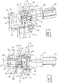
- the figures show a separation unit of a feed device for joining elements 10, which each have a head 14 and a shaft 16.
- the joining elements 10 are preferably screws, in particular flow-hole-forming screws, which may consist of a metal material or else of a plastic material and which have a high-strength coating, in particular in the region of their tips 24.
- the separation unit comprises a joining element receptacle 12 for receiving a joining element 10, a slider 18 displaceable relative to the joining element receptacle 12, and a rotating element 20 around which the joining element 10 accommodated in the joining element receptacle 12 is rotatable upon displacement of the slider 18.
- the separation unit has a connection element 22, to which a hose, not shown in the figures, can be connected, by means of which the joining element 10 delivered by the separation unit can be fed to a joining device.
- the slider 18 is between a receiving position ( Fig. 1 and 2 ) and a submission ( FIGS. 5 and 6 ) displaceable, wherein 3 and 4 purely by way of example show an intermediate position of the slide 18 between its receiving and dispensing position. From Fig. 1 above Fig. 3 to Fig. 5 (or from Fig. 2 above Fig. 4 to Fig. 6 ) So a sequence of movements is shown, while the slider 18 is moved from right to left from its receiving position to its delivery position.
- the receiving position and the delivery position of the slider 18 are defined by two mutually parallel and perpendicular to the direction of displacement of the slider 18 extending stops 26a, 26b, which are connected via a common running between the Fügeelementability 12 and the connecting element 22 bottom plate 28. It is understood that the slide 18 in principle but may be formed without bottom plate.
- a pneumatically actuated drive 30 is provided, for example, a pneumatic cylinder, which moves the slider 18 by means of a piston 32 between the receiving and dispensing position.
- the slider 18 is slidably mounted on the joining element holder 12 by means of a guide device 34, which, as in particular with reference to FIG Fig. 2 to 6 can be seen, by two parallel aligned and extending in the direction of displacement of the slider 18 guide rods 36 is formed.
- the joining element receptacle 12 has an inlet opening 38, through which a joining element 10 enters into the joining element receptacle 12.
- a bar 40 extending parallel to the direction of displacement of the slide 18 is formed on the slide 18, which bar forms the inlet opening 38 during a displacement of the slide 18 blocked from its receiving position in the delivery position ( Fig. 3 and 5 ).
- the latch 40 by means of a fastening means, here two screws 42, to which the dispensing position of the slider 18 defining stop 26 b attached. It is understood that the latch 40 is attached to the slider 18 in other ways can be, for example, cohesively by means of an adhesive. Moreover, it is also conceivable that the latch 40 may be formed integrally with the slider 18.
- the joining element receptacle 12 has a discharge opening 44, which serves to deliver rotated joining elements 10.
- the discharge opening 44 opens into a receiving opening 46 of the connecting element 22.
- aligned in the dispensing position of the slider 18 is provided in the bottom plate 28 opening 48 of the slider 18 with the discharge port 44 and so can give a rotated joining element 10 free.
- the rotation of the joining element 10 takes place about a rotary element 20, which is embodied here in the form of a pivot pin 50.
- the rotary element 20 defines an axis of rotation A about which a joining element 10 accommodated in the joining element receptacle 12 is rotatable and which at least approximately perpendicular to a longitudinal central axis B (FIG. Fig. 2 . 4 and 6 ) of the received in the joining element receiving 12 joining element 10 is aligned.
- the pivot pin 50 is oriented at least approximately perpendicular to the longitudinal center axis B of the joining element 10 received in the joining element receptacle 12.
- an extension 52 extending at least approximately parallel to the direction of displacement is provided on the slide 18, which extension can be brought into engagement with the head 14 of the joining element 10.
- the extension 52 is attached to the dispensing position of the slider 18 defining stop 26b, here by means of two screws 42. It is understood that the extension 52 but also cohesively connected to the slider 18 or be integrally formed with the slider 18 can.
- the extension 52 has an end face 54, which is accommodated in the receiving element receptacle 12 in the receiving position, ie, unrotated, joining element 10 on, from which a in the direction of the direction of displacement of the slider 18 extending collar 56 emerges.
- the collar 56 is aligned with a guide 58 designed as a guide ( Fig. 2 ), which serves to guide the joining element 10 accommodated in the joining element receptacle 12 during its rotation.
- the guideway 58 extends at least partially circularly around the axis of rotation A of the rotary member 20 and further comprises two parallel aligned guide walls 60, which receive the shaft 16 of a received in the Fügeelementaid 12 joining member between them and between which the extension 52 in a shift the slider 18 is movable.
- both the joining element receptacle 12 and the extension 52 each have a recess 62, 64.
- the recess 62 of the joining element holder 12 extends, starting from the rotary element 20, downwards in the direction of the bottom plate 28 of the slide 18 or of the connecting element 22 and has a V shape in the longitudinal section of the separating unit (FIG. Fig. 2 . 4 and 6 ).
- the extension 52 has an arcuate recess 64 on its underside facing the rotary element 20. It is conceivable that the respective cutouts 62, 64 may also have a different shape as long as the tip 24 of the joining element 10 does not touch the joining element receptacle 12 or the extension 52 during a rotation of the joining element 10.
- a joining element 10 is received by the joining element receptacle 12 in a vertical first orientation, the head 14 of the joining element 10 being held on its underside facing the shaft 16 on the one hand by the guide track 58 and on the other hand by the collar 56 such that the tip 24 of the shaft 16 is non-contact in the recess 62 of the joining element holder 12 dips.
- the shaft 16 of the joining element 10 engages with the pivot pin 50 and the joining element 10 is rotated about the rotary member 20, while the underside of the head 14 runs on the guide track 58 ( 3 and 4 ). If the slider 18 has arrived in its delivery position ( FIGS.
- the joining element 10 is rotated with respect to its first orientation in an oblique second orientation and the joining element 10 falls due to gravity head first into the connecting element 22, from where it can be fed via the hose, not shown, the joining device. It is understood that the joining element 10 can be removed not only by gravity from the joining element holder 12, but also, for example, by means of compressed air.
- the inverted joining element 10 with the head 14 advances to the joining device, where it is rotated by a turning device (not shown) upstream of the joining device into an orientation in which the tip 24 points ahead.
- the slider 18 is pushed back into its receiving position, so that a subsequent joining element 10 can be received and rotated in the joining element holder 12 of the separation unit.
Landscapes
- Engineering & Computer Science (AREA)
- Mechanical Engineering (AREA)
- Feeding Of Articles To Conveyors (AREA)
- Transmission Devices (AREA)
- Details Of Spanners, Wrenches, And Screw Drivers And Accessories (AREA)
- Special Conveying (AREA)
- Lining Or Joining Of Plastics Or The Like (AREA)
- Orthopedics, Nursing, And Contraception (AREA)
- Branching, Merging, And Special Transfer Between Conveyors (AREA)
Priority Applications (1)
| Application Number | Priority Date | Filing Date | Title |
|---|---|---|---|
| PL17206646T PL3345720T3 (pl) | 2017-01-10 | 2017-12-12 | Jednostka oddzielająca |
Applications Claiming Priority (1)
| Application Number | Priority Date | Filing Date | Title |
|---|---|---|---|
| DE102017100385.1A DE102017100385A1 (de) | 2017-01-10 | 2017-01-10 | Trennungseinheit |
Publications (2)
| Publication Number | Publication Date |
|---|---|
| EP3345720A1 true EP3345720A1 (fr) | 2018-07-11 |
| EP3345720B1 EP3345720B1 (fr) | 2019-08-28 |
Family
ID=60673475
Family Applications (1)
| Application Number | Title | Priority Date | Filing Date |
|---|---|---|---|
| EP17206646.6A Not-in-force EP3345720B1 (fr) | 2017-01-10 | 2017-12-12 | Unité de séparation |
Country Status (10)
| Country | Link |
|---|---|
| US (1) | US10569371B2 (fr) |
| EP (1) | EP3345720B1 (fr) |
| JP (1) | JP6921729B2 (fr) |
| KR (1) | KR102470582B1 (fr) |
| CN (1) | CN108284313A (fr) |
| DE (1) | DE102017100385A1 (fr) |
| ES (1) | ES2759488T3 (fr) |
| HU (1) | HUE046049T2 (fr) |
| MX (1) | MX378223B (fr) |
| PL (1) | PL3345720T3 (fr) |
Families Citing this family (3)
| Publication number | Priority date | Publication date | Assignee | Title |
|---|---|---|---|---|
| CN112591467B (zh) * | 2020-12-03 | 2022-05-17 | 博众精工科技股份有限公司 | 一种柔性输送设备 |
| WO2022209979A1 (fr) * | 2021-03-30 | 2022-10-06 | 新明和工業株式会社 | Dispositif d'amenée de bouchons en caoutchouc |
| DE102021134409A1 (de) | 2021-12-22 | 2023-06-22 | Tox Pressotechnik Gmbh & Co. Kg | Vereinzelungsvorrichtung und Zuführsystem |
Citations (7)
| Publication number | Priority date | Publication date | Assignee | Title |
|---|---|---|---|---|
| JPS4892676U (fr) * | 1972-02-10 | 1973-11-07 | ||
| JPS6061411A (ja) * | 1983-09-13 | 1985-04-09 | Canon Inc | ワ−ク反転移送装置 |
| JPH02139133A (ja) * | 1988-11-18 | 1990-05-29 | Mitsubishi Automob Eng Co Ltd | ノックピンの自動供給装置 |
| JPH02105919U (fr) * | 1989-02-08 | 1990-08-23 | ||
| EP0644017A1 (fr) * | 1993-09-16 | 1995-03-22 | Emhart Inc. | Séparateur dispositif d'alimentation pour élément de fixation à tête |
| US6357109B1 (en) * | 1999-09-06 | 2002-03-19 | Yugenkaisha Shinjo Seisakusho | Apparatus for automatic fixation of self-piercing fasteners on an article |
| US20030116038A1 (en) * | 1999-12-17 | 2003-06-26 | Ian Gaskin | Press and delivery system for a press |
Family Cites Families (15)
| Publication number | Priority date | Publication date | Assignee | Title |
|---|---|---|---|---|
| US3871295A (en) * | 1973-09-04 | 1975-03-18 | Hartnett Co R W | Capsule orienting apparatus and method of spin printing |
| IT1101040B (it) * | 1978-11-09 | 1985-09-28 | Facchini Libero | Orientatore di capsule,particolarmente per macchine opercolatrici |
| SE431417B (sv) * | 1982-04-28 | 1984-02-06 | Jonny Karl Gyris Andersson | Anordning for indrivning av festelement |
| US4721230A (en) * | 1986-01-24 | 1988-01-26 | Eli Lilly And Company | Capsule rectification apparatus |
| US4828142A (en) * | 1986-01-24 | 1989-05-09 | Eli Lilly & Company | Capsule rectification apparatus |
| US5291645A (en) * | 1989-12-01 | 1994-03-08 | Yoshitaka Aoyama | Method and apparatus for feeding and tightening threaded parts |
| US8703054B2 (en) * | 2004-06-02 | 2014-04-22 | Arkray, Inc. | Direction selection mechanism for analytical tool, and analytical device |
| US7367484B2 (en) * | 2006-01-06 | 2008-05-06 | Gm Global Technology Operations, Inc. | Automatic fastener loader |
| DE102007009618B4 (de) * | 2007-02-26 | 2010-03-18 | Gesipa Blindniettechnik Gmbh | Setzvorrichtung für eine Befestigungseinheit |
| JP5452272B2 (ja) * | 2010-02-12 | 2014-03-26 | 株式会社大武ルート工業 | 自動ネジ締め装置 |
| JP4995302B2 (ja) * | 2010-05-06 | 2012-08-08 | ピアス販売株式会社 | 締結部品の整列供給装置 |
| DE102012001086A1 (de) * | 2012-01-20 | 2013-07-25 | Profil Verbindungstechnik Gmbh & Co. Kg | Bolzenelement und Verfahren zur Anbringung eines Bolzenelements an einem Bauteil aus einem Verbundwerkstoff |
| TWI471199B (zh) * | 2012-10-26 | 2015-02-01 | Ind Tech Res Inst | 自動鎖螺絲機 |
| GB2508644A (en) * | 2012-12-07 | 2014-06-11 | Perrin Knight | Automated orientation and fastening of screws and nails |
| US9662754B2 (en) * | 2014-10-01 | 2017-05-30 | Honda Motor Co., Ltd. | Automatic fastener driving system, apparatus and method |
-
2017
- 2017-01-10 DE DE102017100385.1A patent/DE102017100385A1/de not_active Withdrawn
- 2017-12-12 PL PL17206646T patent/PL3345720T3/pl unknown
- 2017-12-12 HU HUE17206646A patent/HUE046049T2/hu unknown
- 2017-12-12 EP EP17206646.6A patent/EP3345720B1/fr not_active Not-in-force
- 2017-12-12 ES ES17206646T patent/ES2759488T3/es active Active
- 2017-12-15 JP JP2017240138A patent/JP6921729B2/ja not_active Expired - Fee Related
- 2017-12-20 MX MX2017017086A patent/MX378223B/es unknown
-
2018
- 2018-01-03 US US15/861,630 patent/US10569371B2/en not_active Expired - Fee Related
- 2018-01-05 CN CN201810011620.3A patent/CN108284313A/zh active Pending
- 2018-01-10 KR KR1020180003299A patent/KR102470582B1/ko active Active
Patent Citations (7)
| Publication number | Priority date | Publication date | Assignee | Title |
|---|---|---|---|---|
| JPS4892676U (fr) * | 1972-02-10 | 1973-11-07 | ||
| JPS6061411A (ja) * | 1983-09-13 | 1985-04-09 | Canon Inc | ワ−ク反転移送装置 |
| JPH02139133A (ja) * | 1988-11-18 | 1990-05-29 | Mitsubishi Automob Eng Co Ltd | ノックピンの自動供給装置 |
| JPH02105919U (fr) * | 1989-02-08 | 1990-08-23 | ||
| EP0644017A1 (fr) * | 1993-09-16 | 1995-03-22 | Emhart Inc. | Séparateur dispositif d'alimentation pour élément de fixation à tête |
| US6357109B1 (en) * | 1999-09-06 | 2002-03-19 | Yugenkaisha Shinjo Seisakusho | Apparatus for automatic fixation of self-piercing fasteners on an article |
| US20030116038A1 (en) * | 1999-12-17 | 2003-06-26 | Ian Gaskin | Press and delivery system for a press |
Also Published As
| Publication number | Publication date |
|---|---|
| DE102017100385A1 (de) | 2018-07-12 |
| KR102470582B1 (ko) | 2022-11-24 |
| MX2017017086A (es) | 2018-11-09 |
| KR20180082358A (ko) | 2018-07-18 |
| JP2018111603A (ja) | 2018-07-19 |
| EP3345720B1 (fr) | 2019-08-28 |
| US10569371B2 (en) | 2020-02-25 |
| HUE046049T2 (hu) | 2020-01-28 |
| CN108284313A (zh) | 2018-07-17 |
| PL3345720T3 (pl) | 2020-06-15 |
| US20180193966A1 (en) | 2018-07-12 |
| JP6921729B2 (ja) | 2021-08-18 |
| ES2759488T3 (es) | 2020-05-11 |
| MX378223B (es) | 2025-03-10 |
Similar Documents
| Publication | Publication Date | Title |
|---|---|---|
| EP0117557A1 (fr) | Palette porte-pièces sur des machines-outils | |
| EP3345720B1 (fr) | Unité de séparation | |
| EP0125529A2 (fr) | Dispositif de changement d'outil pour machine-outil | |
| EP3165287A1 (fr) | Tete de buse destinee a appliquer un materiau isolant | |
| DE102015121762A1 (de) | Düsenanordnung für fließfähige Substanzen | |
| EP3285958A1 (fr) | Magasin | |
| DE112022004944T5 (de) | Zuführanordnung und System | |
| EP3202518A1 (fr) | Dispositif pour l'enfilage du fil-electrode d'une machine d'electro-erosion | |
| EP0287777A2 (fr) | Dispositif de serrage d'outils ou de pièces, ayant une manche cylindrique | |
| DE69510264T2 (de) | Zuführvorrichtung für Elemente, insbesondere für Elemente mit Kopf | |
| DE102013211128A1 (de) | Vorrichtung zur Aufnahme von Fügeelementen sowie Setzvorrichtung dafür | |
| DE102010014246B3 (de) | Drahtbearbeitungsmaschine | |
| DE10222248A1 (de) | Zuführvorrichtung für Punktschweißelektrodenkappen | |
| EP0325728B1 (fr) | Mandrin pour tige filetée | |
| DE102012111267A1 (de) | Förderkanal einer Schwingfördereinrichtung | |
| AT393256B (de) | Einrichtung zur orientierung von stueckerzeugnissen in zufuehrungseinheiten von aggregaten | |
| DE102016124672A1 (de) | ECM-Werkzeugmaschine sowie Verfahren zum elektrochemischen Bearbeiten | |
| DE19934209C2 (de) | Vereinzelungsvorrichtung für Kleinteile | |
| WO2021023580A1 (fr) | Robot d'assemblage comprenant un séparateur à tambour | |
| WO2002094495A1 (fr) | Dispositif de remplacement d'embouts d'electrodes de soudage par points | |
| DE102022103169B3 (de) | Klinke | |
| DD267939A5 (de) | Montagevorrichtung fuer die einzelnen teile eines beschlagelementes | |
| DE2753337B1 (de) | Spritzgiessform zum Herstellen eines dosenfoermigen Spitzers mit einem umspritzten Messer | |
| EP0212164A1 (fr) | Dispositif pour amener en ligne des ressorts hélicoidaux à une station de travail | |
| DE2332019C3 (de) | Schaltbarer Mehrfachwerkzeughalter |
Legal Events
| Date | Code | Title | Description |
|---|---|---|---|
| PUAI | Public reference made under article 153(3) epc to a published international application that has entered the european phase |
Free format text: ORIGINAL CODE: 0009012 |
|
| STAA | Information on the status of an ep patent application or granted ep patent |
Free format text: STATUS: THE APPLICATION HAS BEEN PUBLISHED |
|
| AK | Designated contracting states |
Kind code of ref document: A1 Designated state(s): AL AT BE BG CH CY CZ DE DK EE ES FI FR GB GR HR HU IE IS IT LI LT LU LV MC MK MT NL NO PL PT RO RS SE SI SK SM TR |
|
| AX | Request for extension of the european patent |
Extension state: BA ME |
|
| STAA | Information on the status of an ep patent application or granted ep patent |
Free format text: STATUS: REQUEST FOR EXAMINATION WAS MADE |
|
| 17P | Request for examination filed |
Effective date: 20181224 |
|
| RBV | Designated contracting states (corrected) |
Designated state(s): AL AT BE BG CH CY CZ DE DK EE ES FI FR GB GR HR HU IE IS IT LI LT LU LV MC MK MT NL NO PL PT RO RS SE SI SK SM TR |
|
| GRAP | Despatch of communication of intention to grant a patent |
Free format text: ORIGINAL CODE: EPIDOSNIGR1 |
|
| STAA | Information on the status of an ep patent application or granted ep patent |
Free format text: STATUS: GRANT OF PATENT IS INTENDED |
|
| INTG | Intention to grant announced |
Effective date: 20190306 |
|
| GRAS | Grant fee paid |
Free format text: ORIGINAL CODE: EPIDOSNIGR3 |
|
| GRAA | (expected) grant |
Free format text: ORIGINAL CODE: 0009210 |
|
| STAA | Information on the status of an ep patent application or granted ep patent |
Free format text: STATUS: THE PATENT HAS BEEN GRANTED |
|
| AK | Designated contracting states |
Kind code of ref document: B1 Designated state(s): AL AT BE BG CH CY CZ DE DK EE ES FI FR GB GR HR HU IE IS IT LI LT LU LV MC MK MT NL NO PL PT RO RS SE SI SK SM TR |
|
| REG | Reference to a national code |
Ref country code: GB Ref legal event code: FG4D Free format text: NOT ENGLISH |
|
| REG | Reference to a national code |
Ref country code: CH Ref legal event code: EP |
|
| REG | Reference to a national code |
Ref country code: DE Ref legal event code: R096 Ref document number: 502017002153 Country of ref document: DE |
|
| REG | Reference to a national code |
Ref country code: AT Ref legal event code: REF Ref document number: 1171798 Country of ref document: AT Kind code of ref document: T Effective date: 20190915 |
|
| REG | Reference to a national code |
Ref country code: IE Ref legal event code: FG4D Free format text: LANGUAGE OF EP DOCUMENT: GERMAN |
|
| REG | Reference to a national code |
Ref country code: SE Ref legal event code: TRGR |
|
| REG | Reference to a national code |
Ref country code: NL Ref legal event code: MP Effective date: 20190828 |
|
| REG | Reference to a national code |
Ref country code: LT Ref legal event code: MG4D |
|
| REG | Reference to a national code |
Ref country code: HU Ref legal event code: AG4A Ref document number: E046049 Country of ref document: HU |
|
| PG25 | Lapsed in a contracting state [announced via postgrant information from national office to epo] |
Ref country code: FI Free format text: LAPSE BECAUSE OF FAILURE TO SUBMIT A TRANSLATION OF THE DESCRIPTION OR TO PAY THE FEE WITHIN THE PRESCRIBED TIME-LIMIT Effective date: 20190828 Ref country code: NO Free format text: LAPSE BECAUSE OF FAILURE TO SUBMIT A TRANSLATION OF THE DESCRIPTION OR TO PAY THE FEE WITHIN THE PRESCRIBED TIME-LIMIT Effective date: 20191128 Ref country code: PT Free format text: LAPSE BECAUSE OF FAILURE TO SUBMIT A TRANSLATION OF THE DESCRIPTION OR TO PAY THE FEE WITHIN THE PRESCRIBED TIME-LIMIT Effective date: 20191230 Ref country code: BG Free format text: LAPSE BECAUSE OF FAILURE TO SUBMIT A TRANSLATION OF THE DESCRIPTION OR TO PAY THE FEE WITHIN THE PRESCRIBED TIME-LIMIT Effective date: 20191128 Ref country code: NL Free format text: LAPSE BECAUSE OF FAILURE TO SUBMIT A TRANSLATION OF THE DESCRIPTION OR TO PAY THE FEE WITHIN THE PRESCRIBED TIME-LIMIT Effective date: 20190828 Ref country code: HR Free format text: LAPSE BECAUSE OF FAILURE TO SUBMIT A TRANSLATION OF THE DESCRIPTION OR TO PAY THE FEE WITHIN THE PRESCRIBED TIME-LIMIT Effective date: 20190828 Ref country code: LT Free format text: LAPSE BECAUSE OF FAILURE TO SUBMIT A TRANSLATION OF THE DESCRIPTION OR TO PAY THE FEE WITHIN THE PRESCRIBED TIME-LIMIT Effective date: 20190828 |
|
| REG | Reference to a national code |
Ref country code: SK Ref legal event code: T3 Ref document number: E 32800 Country of ref document: SK |
|
| PG25 | Lapsed in a contracting state [announced via postgrant information from national office to epo] |
Ref country code: AL Free format text: LAPSE BECAUSE OF FAILURE TO SUBMIT A TRANSLATION OF THE DESCRIPTION OR TO PAY THE FEE WITHIN THE PRESCRIBED TIME-LIMIT Effective date: 20190828 Ref country code: LV Free format text: LAPSE BECAUSE OF FAILURE TO SUBMIT A TRANSLATION OF THE DESCRIPTION OR TO PAY THE FEE WITHIN THE PRESCRIBED TIME-LIMIT Effective date: 20190828 Ref country code: GR Free format text: LAPSE BECAUSE OF FAILURE TO SUBMIT A TRANSLATION OF THE DESCRIPTION OR TO PAY THE FEE WITHIN THE PRESCRIBED TIME-LIMIT Effective date: 20191129 Ref country code: RS Free format text: LAPSE BECAUSE OF FAILURE TO SUBMIT A TRANSLATION OF THE DESCRIPTION OR TO PAY THE FEE WITHIN THE PRESCRIBED TIME-LIMIT Effective date: 20190828 Ref country code: IS Free format text: LAPSE BECAUSE OF FAILURE TO SUBMIT A TRANSLATION OF THE DESCRIPTION OR TO PAY THE FEE WITHIN THE PRESCRIBED TIME-LIMIT Effective date: 20191228 |
|
| PG25 | Lapsed in a contracting state [announced via postgrant information from national office to epo] |
Ref country code: TR Free format text: LAPSE BECAUSE OF FAILURE TO SUBMIT A TRANSLATION OF THE DESCRIPTION OR TO PAY THE FEE WITHIN THE PRESCRIBED TIME-LIMIT Effective date: 20190828 |
|
| PG25 | Lapsed in a contracting state [announced via postgrant information from national office to epo] |
Ref country code: DK Free format text: LAPSE BECAUSE OF FAILURE TO SUBMIT A TRANSLATION OF THE DESCRIPTION OR TO PAY THE FEE WITHIN THE PRESCRIBED TIME-LIMIT Effective date: 20190828 Ref country code: RO Free format text: LAPSE BECAUSE OF FAILURE TO SUBMIT A TRANSLATION OF THE DESCRIPTION OR TO PAY THE FEE WITHIN THE PRESCRIBED TIME-LIMIT Effective date: 20190828 Ref country code: EE Free format text: LAPSE BECAUSE OF FAILURE TO SUBMIT A TRANSLATION OF THE DESCRIPTION OR TO PAY THE FEE WITHIN THE PRESCRIBED TIME-LIMIT Effective date: 20190828 |
|
| REG | Reference to a national code |
Ref country code: ES Ref legal event code: FG2A Ref document number: 2759488 Country of ref document: ES Kind code of ref document: T3 Effective date: 20200511 |
|
| PG25 | Lapsed in a contracting state [announced via postgrant information from national office to epo] |
Ref country code: SM Free format text: LAPSE BECAUSE OF FAILURE TO SUBMIT A TRANSLATION OF THE DESCRIPTION OR TO PAY THE FEE WITHIN THE PRESCRIBED TIME-LIMIT Effective date: 20190828 Ref country code: IS Free format text: LAPSE BECAUSE OF FAILURE TO SUBMIT A TRANSLATION OF THE DESCRIPTION OR TO PAY THE FEE WITHIN THE PRESCRIBED TIME-LIMIT Effective date: 20200224 |
|
| REG | Reference to a national code |
Ref country code: DE Ref legal event code: R097 Ref document number: 502017002153 Country of ref document: DE |
|
| PLBE | No opposition filed within time limit |
Free format text: ORIGINAL CODE: 0009261 |
|
| STAA | Information on the status of an ep patent application or granted ep patent |
Free format text: STATUS: NO OPPOSITION FILED WITHIN TIME LIMIT |
|
| PG2D | Information on lapse in contracting state deleted |
Ref country code: IS |
|
| 26N | No opposition filed |
Effective date: 20200603 |
|
| PG25 | Lapsed in a contracting state [announced via postgrant information from national office to epo] |
Ref country code: MC Free format text: LAPSE BECAUSE OF FAILURE TO SUBMIT A TRANSLATION OF THE DESCRIPTION OR TO PAY THE FEE WITHIN THE PRESCRIBED TIME-LIMIT Effective date: 20190828 Ref country code: SI Free format text: LAPSE BECAUSE OF FAILURE TO SUBMIT A TRANSLATION OF THE DESCRIPTION OR TO PAY THE FEE WITHIN THE PRESCRIBED TIME-LIMIT Effective date: 20190828 |
|
| PG25 | Lapsed in a contracting state [announced via postgrant information from national office to epo] |
Ref country code: LU Free format text: LAPSE BECAUSE OF NON-PAYMENT OF DUE FEES Effective date: 20191212 Ref country code: IE Free format text: LAPSE BECAUSE OF NON-PAYMENT OF DUE FEES Effective date: 20191212 |
|
| PGFP | Annual fee paid to national office [announced via postgrant information from national office to epo] |
Ref country code: FR Payment date: 20201223 Year of fee payment: 4 Ref country code: SE Payment date: 20201221 Year of fee payment: 4 Ref country code: IT Payment date: 20201231 Year of fee payment: 4 Ref country code: CZ Payment date: 20201214 Year of fee payment: 4 |
|
| PGFP | Annual fee paid to national office [announced via postgrant information from national office to epo] |
Ref country code: SK Payment date: 20201214 Year of fee payment: 4 Ref country code: BE Payment date: 20201221 Year of fee payment: 4 Ref country code: PL Payment date: 20201204 Year of fee payment: 4 |
|
| PG25 | Lapsed in a contracting state [announced via postgrant information from national office to epo] |
Ref country code: CY Free format text: LAPSE BECAUSE OF FAILURE TO SUBMIT A TRANSLATION OF THE DESCRIPTION OR TO PAY THE FEE WITHIN THE PRESCRIBED TIME-LIMIT Effective date: 20190828 |
|
| PGFP | Annual fee paid to national office [announced via postgrant information from national office to epo] |
Ref country code: DE Payment date: 20210225 Year of fee payment: 4 Ref country code: ES Payment date: 20210223 Year of fee payment: 4 Ref country code: HU Payment date: 20210131 Year of fee payment: 4 |
|
| PG25 | Lapsed in a contracting state [announced via postgrant information from national office to epo] |
Ref country code: MT Free format text: LAPSE BECAUSE OF FAILURE TO SUBMIT A TRANSLATION OF THE DESCRIPTION OR TO PAY THE FEE WITHIN THE PRESCRIBED TIME-LIMIT Effective date: 20190828 |
|
| REG | Reference to a national code |
Ref country code: CH Ref legal event code: PL |
|
| PG25 | Lapsed in a contracting state [announced via postgrant information from national office to epo] |
Ref country code: CH Free format text: LAPSE BECAUSE OF NON-PAYMENT OF DUE FEES Effective date: 20201231 Ref country code: LI Free format text: LAPSE BECAUSE OF NON-PAYMENT OF DUE FEES Effective date: 20201231 |
|
| PG25 | Lapsed in a contracting state [announced via postgrant information from national office to epo] |
Ref country code: MK Free format text: LAPSE BECAUSE OF FAILURE TO SUBMIT A TRANSLATION OF THE DESCRIPTION OR TO PAY THE FEE WITHIN THE PRESCRIBED TIME-LIMIT Effective date: 20190828 |
|
| REG | Reference to a national code |
Ref country code: DE Ref legal event code: R119 Ref document number: 502017002153 Country of ref document: DE |
|
| REG | Reference to a national code |
Ref country code: SK Ref legal event code: MM4A Ref document number: E 32800 Country of ref document: SK Effective date: 20211212 |
|
| PG25 | Lapsed in a contracting state [announced via postgrant information from national office to epo] |
Ref country code: CZ Free format text: LAPSE BECAUSE OF NON-PAYMENT OF DUE FEES Effective date: 20211212 |
|
| REG | Reference to a national code |
Ref country code: SE Ref legal event code: EUG |
|
| GBPC | Gb: european patent ceased through non-payment of renewal fee |
Effective date: 20211212 |
|
| REG | Reference to a national code |
Ref country code: BE Ref legal event code: MM Effective date: 20211231 |
|
| PG25 | Lapsed in a contracting state [announced via postgrant information from national office to epo] |
Ref country code: SK Free format text: LAPSE BECAUSE OF NON-PAYMENT OF DUE FEES Effective date: 20211212 Ref country code: SE Free format text: LAPSE BECAUSE OF NON-PAYMENT OF DUE FEES Effective date: 20211213 Ref country code: GB Free format text: LAPSE BECAUSE OF NON-PAYMENT OF DUE FEES Effective date: 20211212 Ref country code: DE Free format text: LAPSE BECAUSE OF NON-PAYMENT OF DUE FEES Effective date: 20220701 |
|
| PG25 | Lapsed in a contracting state [announced via postgrant information from national office to epo] |
Ref country code: HU Free format text: LAPSE BECAUSE OF NON-PAYMENT OF DUE FEES Effective date: 20211213 Ref country code: FR Free format text: LAPSE BECAUSE OF NON-PAYMENT OF DUE FEES Effective date: 20211231 Ref country code: BE Free format text: LAPSE BECAUSE OF NON-PAYMENT OF DUE FEES Effective date: 20211231 |
|
| PG25 | Lapsed in a contracting state [announced via postgrant information from national office to epo] |
Ref country code: IT Free format text: LAPSE BECAUSE OF NON-PAYMENT OF DUE FEES Effective date: 20211212 |
|
| PGFP | Annual fee paid to national office [announced via postgrant information from national office to epo] |
Ref country code: AT Payment date: 20221222 Year of fee payment: 6 |
|
| REG | Reference to a national code |
Ref country code: ES Ref legal event code: FD2A Effective date: 20230206 |
|
| PG25 | Lapsed in a contracting state [announced via postgrant information from national office to epo] |
Ref country code: ES Free format text: LAPSE BECAUSE OF NON-PAYMENT OF DUE FEES Effective date: 20211213 |
|
| PG25 | Lapsed in a contracting state [announced via postgrant information from national office to epo] |
Ref country code: PL Free format text: LAPSE BECAUSE OF NON-PAYMENT OF DUE FEES Effective date: 20211212 |
|
| REG | Reference to a national code |
Ref country code: AT Ref legal event code: MM01 Ref document number: 1171798 Country of ref document: AT Kind code of ref document: T Effective date: 20231212 |
|
| PG25 | Lapsed in a contracting state [announced via postgrant information from national office to epo] |
Ref country code: AT Free format text: LAPSE BECAUSE OF NON-PAYMENT OF DUE FEES Effective date: 20231212 |
|
| PG25 | Lapsed in a contracting state [announced via postgrant information from national office to epo] |
Ref country code: AT Free format text: LAPSE BECAUSE OF NON-PAYMENT OF DUE FEES Effective date: 20231212 |