EP3345737A1 - System zur verbindung zwischen teilen einer struktur - Google Patents
System zur verbindung zwischen teilen einer struktur Download PDFInfo
- Publication number
- EP3345737A1 EP3345737A1 EP15902857.0A EP15902857A EP3345737A1 EP 3345737 A1 EP3345737 A1 EP 3345737A1 EP 15902857 A EP15902857 A EP 15902857A EP 3345737 A1 EP3345737 A1 EP 3345737A1
- Authority
- EP
- European Patent Office
- Prior art keywords
- parts
- connection
- areas
- mold
- resin
- Prior art date
- Legal status (The legal status is an assumption and is not a legal conclusion. Google has not performed a legal analysis and makes no representation as to the accuracy of the status listed.)
- Withdrawn
Links
- 239000011347 resin Substances 0.000 claims abstract description 24
- 229920005989 resin Polymers 0.000 claims abstract description 24
- 239000000853 adhesive Substances 0.000 claims abstract description 7
- 230000001070 adhesive effect Effects 0.000 claims abstract description 7
- 238000000576 coating method Methods 0.000 claims description 19
- 238000002347 injection Methods 0.000 claims description 19
- 239000007924 injection Substances 0.000 claims description 19
- 239000011248 coating agent Substances 0.000 claims description 18
- 230000015572 biosynthetic process Effects 0.000 claims description 15
- 238000005755 formation reaction Methods 0.000 claims description 15
- 239000000463 material Substances 0.000 claims description 5
- 230000006978 adaptation Effects 0.000 claims description 2
- 239000000835 fiber Substances 0.000 claims description 2
- 238000012876 topography Methods 0.000 claims description 2
- 238000011282 treatment Methods 0.000 claims description 2
- 239000011247 coating layer Substances 0.000 claims 3
- 238000000034 method Methods 0.000 description 10
- 238000005192 partition Methods 0.000 description 4
- 230000003014 reinforcing effect Effects 0.000 description 3
- 238000003466 welding Methods 0.000 description 3
- 229920000049 Carbon (fiber) Polymers 0.000 description 2
- 239000004917 carbon fiber Substances 0.000 description 2
- 230000000694 effects Effects 0.000 description 2
- 239000002184 metal Substances 0.000 description 2
- 239000002131 composite material Substances 0.000 description 1
- 238000009434 installation Methods 0.000 description 1
- 238000004519 manufacturing process Methods 0.000 description 1
- 230000035515 penetration Effects 0.000 description 1
- 230000002787 reinforcement Effects 0.000 description 1
- 238000000926 separation method Methods 0.000 description 1
- 239000007787 solid Substances 0.000 description 1
Images

Classifications
-
- B—PERFORMING OPERATIONS; TRANSPORTING
- B29—WORKING OF PLASTICS; WORKING OF SUBSTANCES IN A PLASTIC STATE IN GENERAL
- B29C—SHAPING OR JOINING OF PLASTICS; SHAPING OF MATERIAL IN A PLASTIC STATE, NOT OTHERWISE PROVIDED FOR; AFTER-TREATMENT OF THE SHAPED PRODUCTS, e.g. REPAIRING
- B29C45/00—Injection moulding, i.e. forcing the required volume of moulding material through a nozzle into a closed mould; Apparatus therefor
- B29C45/14—Injection moulding, i.e. forcing the required volume of moulding material through a nozzle into a closed mould; Apparatus therefor incorporating preformed parts or layers, e.g. injection moulding around inserts or for coating articles
- B29C45/14467—Joining articles or parts of a single article
-
- B—PERFORMING OPERATIONS; TRANSPORTING
- B29—WORKING OF PLASTICS; WORKING OF SUBSTANCES IN A PLASTIC STATE IN GENERAL
- B29C—SHAPING OR JOINING OF PLASTICS; SHAPING OF MATERIAL IN A PLASTIC STATE, NOT OTHERWISE PROVIDED FOR; AFTER-TREATMENT OF THE SHAPED PRODUCTS, e.g. REPAIRING
- B29C45/00—Injection moulding, i.e. forcing the required volume of moulding material through a nozzle into a closed mould; Apparatus therefor
- B29C45/14—Injection moulding, i.e. forcing the required volume of moulding material through a nozzle into a closed mould; Apparatus therefor incorporating preformed parts or layers, e.g. injection moulding around inserts or for coating articles
- B29C45/14336—Coating a portion of the article, e.g. the edge of the article
- B29C45/14344—Moulding in or through a hole in the article, e.g. outsert moulding
-
- B—PERFORMING OPERATIONS; TRANSPORTING
- B29—WORKING OF PLASTICS; WORKING OF SUBSTANCES IN A PLASTIC STATE IN GENERAL
- B29C—SHAPING OR JOINING OF PLASTICS; SHAPING OF MATERIAL IN A PLASTIC STATE, NOT OTHERWISE PROVIDED FOR; AFTER-TREATMENT OF THE SHAPED PRODUCTS, e.g. REPAIRING
- B29C45/00—Injection moulding, i.e. forcing the required volume of moulding material through a nozzle into a closed mould; Apparatus therefor
- B29C45/14—Injection moulding, i.e. forcing the required volume of moulding material through a nozzle into a closed mould; Apparatus therefor incorporating preformed parts or layers, e.g. injection moulding around inserts or for coating articles
- B29C45/14598—Coating tubular articles
- B29C45/14614—Joining tubular articles
-
- B—PERFORMING OPERATIONS; TRANSPORTING
- B29—WORKING OF PLASTICS; WORKING OF SUBSTANCES IN A PLASTIC STATE IN GENERAL
- B29C—SHAPING OR JOINING OF PLASTICS; SHAPING OF MATERIAL IN A PLASTIC STATE, NOT OTHERWISE PROVIDED FOR; AFTER-TREATMENT OF THE SHAPED PRODUCTS, e.g. REPAIRING
- B29C70/00—Shaping composites, i.e. plastics material comprising reinforcements, fillers or preformed parts, e.g. inserts
- B29C70/68—Shaping composites, i.e. plastics material comprising reinforcements, fillers or preformed parts, e.g. inserts by incorporating or moulding on preformed parts, e.g. inserts or layers, e.g. foam blocks
- B29C70/74—Moulding material on a relatively small portion of the preformed part, e.g. outsert moulding
- B29C70/76—Moulding on edges or extremities of the preformed part
-
- F—MECHANICAL ENGINEERING; LIGHTING; HEATING; WEAPONS; BLASTING
- F16—ENGINEERING ELEMENTS AND UNITS; GENERAL MEASURES FOR PRODUCING AND MAINTAINING EFFECTIVE FUNCTIONING OF MACHINES OR INSTALLATIONS; THERMAL INSULATION IN GENERAL
- F16L—PIPES; JOINTS OR FITTINGS FOR PIPES; SUPPORTS FOR PIPES, CABLES OR PROTECTIVE TUBING; MEANS FOR THERMAL INSULATION IN GENERAL
- F16L25/00—Construction or details of pipe joints not provided for in, or of interest apart from, groups F16L13/00 - F16L23/00
- F16L25/02—Construction or details of pipe joints not provided for in, or of interest apart from, groups F16L13/00 - F16L23/00 specially adapted for electrically insulating the two pipe ends of the joint from each other
- F16L25/03—Construction or details of pipe joints not provided for in, or of interest apart from, groups F16L13/00 - F16L23/00 specially adapted for electrically insulating the two pipe ends of the joint from each other in non-disconnectable pipe joints
-
- F—MECHANICAL ENGINEERING; LIGHTING; HEATING; WEAPONS; BLASTING
- F16—ENGINEERING ELEMENTS AND UNITS; GENERAL MEASURES FOR PRODUCING AND MAINTAINING EFFECTIVE FUNCTIONING OF MACHINES OR INSTALLATIONS; THERMAL INSULATION IN GENERAL
- F16L—PIPES; JOINTS OR FITTINGS FOR PIPES; SUPPORTS FOR PIPES, CABLES OR PROTECTIVE TUBING; MEANS FOR THERMAL INSULATION IN GENERAL
- F16L47/00—Connecting arrangements or other fittings specially adapted to be made of plastics or to be used with pipes made of plastics
- F16L47/20—Connecting arrangements or other fittings specially adapted to be made of plastics or to be used with pipes made of plastics based principally on specific properties of plastics
-
- B—PERFORMING OPERATIONS; TRANSPORTING
- B29—WORKING OF PLASTICS; WORKING OF SUBSTANCES IN A PLASTIC STATE IN GENERAL
- B29C—SHAPING OR JOINING OF PLASTICS; SHAPING OF MATERIAL IN A PLASTIC STATE, NOT OTHERWISE PROVIDED FOR; AFTER-TREATMENT OF THE SHAPED PRODUCTS, e.g. REPAIRING
- B29C45/00—Injection moulding, i.e. forcing the required volume of moulding material through a nozzle into a closed mould; Apparatus therefor
- B29C45/14—Injection moulding, i.e. forcing the required volume of moulding material through a nozzle into a closed mould; Apparatus therefor incorporating preformed parts or layers, e.g. injection moulding around inserts or for coating articles
- B29C45/14336—Coating a portion of the article, e.g. the edge of the article
- B29C45/14344—Moulding in or through a hole in the article, e.g. outsert moulding
- B29C2045/14368—Moulding in or through a hole in the article, e.g. outsert moulding holes with means for anchoring the injected material
-
- B—PERFORMING OPERATIONS; TRANSPORTING
- B29—WORKING OF PLASTICS; WORKING OF SUBSTANCES IN A PLASTIC STATE IN GENERAL
- B29K—INDEXING SCHEME ASSOCIATED WITH SUBCLASSES B29B, B29C OR B29D, RELATING TO MOULDING MATERIALS OR TO MATERIALS FOR MOULDS, REINFORCEMENTS, FILLERS OR PREFORMED PARTS, e.g. INSERTS
- B29K2105/00—Condition, form or state of moulded material or of the material to be shaped
- B29K2105/0097—Glues or adhesives, e.g. hot melts or thermofusible adhesives
-
- B—PERFORMING OPERATIONS; TRANSPORTING
- B29—WORKING OF PLASTICS; WORKING OF SUBSTANCES IN A PLASTIC STATE IN GENERAL
- B29L—INDEXING SCHEME ASSOCIATED WITH SUBCLASS B29C, RELATING TO PARTICULAR ARTICLES
- B29L2031/00—Other particular articles
- B29L2031/24—Pipe joints or couplings
-
- B—PERFORMING OPERATIONS; TRANSPORTING
- B29—WORKING OF PLASTICS; WORKING OF SUBSTANCES IN A PLASTIC STATE IN GENERAL
- B29L—INDEXING SCHEME ASSOCIATED WITH SUBCLASS B29C, RELATING TO PARTICULAR ARTICLES
- B29L2031/00—Other particular articles
- B29L2031/30—Vehicles, e.g. ships or aircraft, or body parts thereof
- B29L2031/3091—Bicycles
Definitions
- the present invention relates to a system for connection between parts of a structure and more specifically, parts of a structure that meet in an intersection area, especially parts or components of a rigid or semi-rigid nature, for example, which make up part of the structure of a building, of the frame of a vehicle or bicycle, of any other reinforcement, and that can make up a flat or three-dimensional structure.
- the method of the invention enables carrying out the connection of the components of a structure that meet each other in a simple and cheap way, while at the same time enabling a coating of the connection area and, if desired, of the surfaces adjacent to said area to be obtained, a coating which can be intended to provide mechanical or decorative properties to the assembly and/or define the corresponding surface seen.
- connection between parts that meet each other has been carried out by different systems, depending on the nature of the components to be connected.
- the classic connection systems are welding, screwing and riveting. Similar systems are used for the joints of plastic parts.
- connection processes are complicated as well as expensive.
- the object of the present invention is a method for connecting components of a structure that meet each other, which is independent from the nature of the components to be connected and also from the relative position in which the parts or components meet in order to form a flat or tridimensional structure.
- connection method of the invention comprises the following steps:
- the cited formations can consist of channels, recesses or holes made on the zones or areas of connection that will also be located inside the mold and will be filled with the injected plastic or resin.
- these formations will be made in the parts to be connected in a direction perpendicular to that of the forces that must support said parts.
- the mentioned formations must also consist of protrusions or ribs formed on the outer surface of the zones or areas of connection of the parts to be connected.
- the parts to be connected can have a laminar structure, in which case the holes will cross through the parts.
- the holes will cross through the wall of the parts and the tubular structure will be closed immediately behind the section occupied by said holes, in order to limit the penetration of the melted plastic or resin in the injection operation.
- a plastic or resin coating can be formed by means of the same injection operation carried out to connect the parts or even by means of a subsequent injection operation with a different plastic or resin.
- connections between parts can be carried out by means of the injection of an adhesive plastic or resin, in a melted state, which act as a double mechanical connection by way of welding, (for the adherence of the injected plastic, once solidified, to the surfaces of the occupied areas) and by way of screws or rivets, for the solidified plastic core that occupies the holes or recesses.
- connection method of the invention also enables, on the area of connection between parts, a coating to be obtained based on the same injected plastic in order to carry out the connection or with another different one, compatible with the first one.
- the plastic used to achieve the coating is the same as the one used for the connection between parts, the complete operation, connection and coating, can be achieved in a single mold, in which the parts to be connected will be placed, and in a single injection operation.
- the plastic used for the coating is different than the one used for the connection between parts, two molds and two injection operations will be used, one to complete the connection between parts, in which said parts to be connected are positioned and the injection of the corresponding plastic or resin is performed, and another with greater volume and with the shape of the coating, in which the already connected parts are positioned and a second injection is performed, with the plastic or resin that will make up the coating.
- the coating material used in the second injection can be an expanded type, for lightness and resistance against impacts.
- a second mold will be arranged in which the structure previously formed by means of the first injection will be placed, delimiting the space between this second mold and said structure, which will be filled with the second injection by means of which a coating can be obtained over certain areas or surfaces of the structure.
- said second mold can be designed with cavities or configurations intended for the placement of inserts or parts that can later make up a portion of the coating, for example like outer decorative skin, metal reinforcing elements, etc.
- the additional inserts or parts intended to be mounted in the second mold, before carrying out the second injection can be arranged on flexible laminar templates that are in turn fastened on the inner surface of the mold, thus facilitating the placement of the inserts. Furthermore, the use of the mentioned template would be useful for removing, from the surface of the structure formed, lines corresponding to the separations between the parts that form the mold.
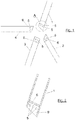
- FIG. 1 In Figure 1 , four tubular parts or components are represented (1, 2, 3 and 4), that must be connected in order to form a structure, flat in the described example, said components being shown in the positions that they will occupy within the structure to be formed.
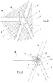
- the parts (1, 2, 3 and 4) to be connected are equipped, close to the areas of connection, with formations that in the examples shown consist of holes (5) that cross through the walls of said parts, as better seen in Figure 2 . If the walls are very thick or if the parts to be connected are solid, the holes (5) can cross through said walls or parts only partially, starting from one of the surfaces thereof.
- the holes (5) are made in the direction perpendicular to the direction in which the forces act in each of the parts, inside the structure of which they will make up part.
- the tubular parts are closed, in a subsequent section close to the section in which the holes (5) are located by means of a transversal partition (6).
- the holes (5) will be made in the parts to be connected in the direction perpendicular to the direction in which the forces act, which must support the structure through each part.
- connection achieved acts with a double effect: a) For the adherence of the resin injected on the walls of the part to be connected, and b) for the mechanical action of the stoppers (12) inside the holes (5).
- a coating (12) can furthermore be obtained, adequately scaling the cavities or gaps of the mold (7), based on the same plastic or resin used for the connection between parts, or by means of a second injection with a different plastic or resin.
- fibers (13) of a resistant nature can be arranged, for example carbon fibers, that can or cannot penetrate into the tubular parts and that would stay occluded in the injected resin or plastic, increasing or reinforcing the effect thereof.
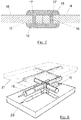
- FIG 7 the butt connection between two essentially flat parts (14 and 15), in which holes (16) are made close to the joint, is shown.
- an adhesive plastic or resin is injected that will make up stoppers (17) that fill the holes (16) as well as a coating (18) over the parts (14 and 15), which acts with the stoppers (17) by way of rivets.
- the system for connection of the invention is applicable in the connection of parts of any nature and configuration that aim to make up a portion of an assembly with a flat or spatial structure.
- the areas of the parts to be connected can be subject, before the arrangement thereof in the mold, to chained treatments to ensure the sticking or connection between the injected material and the parts to be connected.
- the model (7) furthermore can have cavities that, upon being filled with the injected material, provide reinforcing or decorative elements.
- Figure 8 a variant embodiment is shown in which the formations with which the parts to be connected (1, 2, 3, 4) are provided consist of ribs (19) that can run along the surfaces of the areas or zones of the parts to be connected in a longitudinal, transversal or tilted direction.
- ribs (19) that can run along the surfaces of the areas or zones of the parts to be connected in a longitudinal, transversal or tilted direction.
Landscapes
- Engineering & Computer Science (AREA)
- Mechanical Engineering (AREA)
- Manufacturing & Machinery (AREA)
- General Engineering & Computer Science (AREA)
- Chemical & Material Sciences (AREA)
- Composite Materials (AREA)
- Injection Moulding Of Plastics Or The Like (AREA)
- Moulds For Moulding Plastics Or The Like (AREA)
Applications Claiming Priority (1)
| Application Number | Priority Date | Filing Date | Title |
|---|---|---|---|
| PCT/ES2015/070644 WO2017037306A1 (es) | 2015-09-02 | 2015-09-02 | Sistema de unión entre piezas de una estructura |
Publications (2)
| Publication Number | Publication Date |
|---|---|
| EP3345737A1 true EP3345737A1 (de) | 2018-07-11 |
| EP3345737A4 EP3345737A4 (de) | 2018-09-19 |
Family
ID=58186778
Family Applications (1)
| Application Number | Title | Priority Date | Filing Date |
|---|---|---|---|
| EP15902857.0A Withdrawn EP3345737A4 (de) | 2015-09-02 | 2015-09-02 | System zur verbindung zwischen teilen einer struktur |
Country Status (4)
| Country | Link |
|---|---|
| US (1) | US20180243957A1 (de) |
| EP (1) | EP3345737A4 (de) |
| CN (1) | CN108349129A (de) |
| WO (1) | WO2017037306A1 (de) |
Cited By (1)
| Publication number | Priority date | Publication date | Assignee | Title |
|---|---|---|---|---|
| DE102018132886B3 (de) | 2018-12-19 | 2019-12-12 | d&b audiotechnik Verwaltungs GmbH | Verfahren zur Herstellung eines kunststoffbeschichteten Lautsprechergehäuses und kunststoffbeschichtetes Lautsprechergehäuse |
Families Citing this family (1)
| Publication number | Priority date | Publication date | Assignee | Title |
|---|---|---|---|---|
| DE102014224040A1 (de) * | 2014-11-25 | 2016-05-25 | Bayerische Motoren Werke Aktiengesellschaft | Verfahren zu Herstellung einer Strukturbauteilgruppe sowie Strukturbauteilgruppe |
Family Cites Families (17)
| Publication number | Priority date | Publication date | Assignee | Title |
|---|---|---|---|---|
| FR2057558A5 (de) * | 1969-08-27 | 1971-05-21 | Banides Lucien | |
| US4457542A (en) * | 1981-09-21 | 1984-07-03 | Nibco Inc. | Plastic pipe fitting |
| JPS6444247A (en) * | 1987-08-12 | 1989-02-16 | Hitachi Ltd | Apparatus for producing thin sheet |
| CN1039980C (zh) * | 1992-09-25 | 1998-09-30 | 陈勋森 | 复合材料的自行车架及其制造方法 |
| US6726868B1 (en) * | 2000-03-03 | 2004-04-27 | A. Richard, S.E.N.C. | Double molding process whereby a sign is produced on a product while said product is molded |
| DE10022360A1 (de) * | 2000-05-08 | 2001-11-15 | Bayer Ag | Profilverbundbauteil und Verfahren zu seiner Herstellung |
| DE10104035A1 (de) * | 2001-01-31 | 2002-08-01 | Bayerische Motoren Werke Ag | Verfahren zum Herstellen eines Kunststoff-Metall-Verbundkörpers |
| KR100443178B1 (ko) * | 2001-07-04 | 2004-08-04 | 현대엔지니어링 주식회사 | 금형을 이용한 배관연결공법 |
| ITMI20012112A1 (it) * | 2001-10-12 | 2003-04-12 | Aquajet S R L | Metodo di realizzazione di una giunzione di un manicotto di giunzionead uno o piu' tubi di distrubuzione di un fluido |
| US20040100093A1 (en) * | 2002-11-21 | 2004-05-27 | Leigh-Monstevens Keith V. | Co-extruded tube with molded connector |
| US6761187B1 (en) * | 2003-04-03 | 2004-07-13 | Bayer Polymers Llc | Tubular assembly having an internal plug |
| DE10317218A1 (de) * | 2003-04-15 | 2004-11-04 | Bayer Ag | Verfahren zur Herstellung eines Kunststoff-Metall-Verbundbauteils |
| DE10336189A1 (de) * | 2003-08-07 | 2005-03-10 | Daimler Chrysler Ag | Verbindung zwischen zwei Bauteilen und zugehöriges Verbindungsverfahren |
| US20060000321A1 (en) * | 2004-06-30 | 2006-01-05 | Hung-Ming Hu | Hand tool structure |
| US20100117262A1 (en) * | 2008-11-13 | 2010-05-13 | Donald Gringer | Method of dual molding products with logos and other indicia |
| DE102011108156A1 (de) * | 2011-07-20 | 2013-01-24 | Daimler Ag | Verbindungsstruktur für einen Kraftwagen und Verfahren zu deren Herstellung |
| US8717735B2 (en) * | 2011-12-14 | 2014-05-06 | The Boeing Company | Seal with energy-absorbing filler and method of manufacture |
-
2015
- 2015-09-02 US US15/756,886 patent/US20180243957A1/en not_active Abandoned
- 2015-09-02 EP EP15902857.0A patent/EP3345737A4/de not_active Withdrawn
- 2015-09-02 CN CN201580083763.XA patent/CN108349129A/zh active Pending
- 2015-09-02 WO PCT/ES2015/070644 patent/WO2017037306A1/es not_active Ceased
Cited By (2)
| Publication number | Priority date | Publication date | Assignee | Title |
|---|---|---|---|---|
| DE102018132886B3 (de) | 2018-12-19 | 2019-12-12 | d&b audiotechnik Verwaltungs GmbH | Verfahren zur Herstellung eines kunststoffbeschichteten Lautsprechergehäuses und kunststoffbeschichtetes Lautsprechergehäuse |
| US11438681B2 (en) | 2018-12-19 | 2022-09-06 | D&B Audiotechnik Gmbh & Co. Kg | Method for producing a plastic-coated loudspeaker housing and plastic-coated loudspeaker housing |
Also Published As
| Publication number | Publication date |
|---|---|
| US20180243957A1 (en) | 2018-08-30 |
| EP3345737A4 (de) | 2018-09-19 |
| WO2017037306A1 (es) | 2017-03-09 |
| CN108349129A (zh) | 2018-07-31 |
Similar Documents
| Publication | Publication Date | Title |
|---|---|---|
| JP5705330B2 (ja) | ボディモジュール部品およびその製造方法 | |
| CN1222400C (zh) | 异形组合构件及其制造方法 | |
| US20170129545A1 (en) | Frame structure with at least one console for connecting further components, method for producing and motor vehicle body | |
| JP5852556B2 (ja) | 車両製造方法及び車両構造体 | |
| US9512818B2 (en) | Low-cost molded wind turbine blade | |
| US20020109263A1 (en) | Process for preparing composite molded articles by multicomponent injection molding | |
| WO2016092132A1 (es) | Procedimiento y sistema para fabricar una pieza de material compuesto, y pieza obtenida mediante dicho procedimiento | |
| CN101970215A (zh) | 用于制造一体成型的纤维复合部件的方法 | |
| US10384727B2 (en) | Method for producing a node structure with at least two profile components and node structure and vehicle body | |
| CN104842500B (zh) | 用于在纤维复合部件中产生开口的方法和模具 | |
| CN105899819B (zh) | 用于连接至少两个构件的连接部段的方法 | |
| EP3345737A1 (de) | System zur verbindung zwischen teilen einer struktur | |
| US20020125613A1 (en) | Mandrel fabrication for cobond assembly | |
| CN111148682A (zh) | 车辆结构部件和用于制造车辆结构部件的方法 | |
| CN109514772B (zh) | 具有各向异性的热性能的模具工具 | |
| US10611101B2 (en) | Mandrel forming for discrete wing skin stiffeners | |
| DE102011083162A1 (de) | Mehrlagiges Faserverbundbauteil und Verfahren zum Herstellen desselben | |
| US20040206017A1 (en) | Hollow chamber composite article | |
| US10828810B2 (en) | Method for the production of a vehicle body element and vehicle body element | |
| CN112533816B (zh) | 车辆结构构件、模块式系统以及制造车辆结构构件的方法 | |
| US20150151497A1 (en) | Composite assembly and manufacturing method thereof | |
| EP3505332B1 (de) | Selbsttragende verbundstruktur für karosserie- und rahmenteile von kraftfahrzeugen | |
| DE102015014361A1 (de) | Verfahren zur Herstellung einer Knotenstruktur mit wenigstens einem Hohlprofilbauteil, sowie Knotenstruktur und Fahrzeugkarosserie | |
| CN104421600B (zh) | 对纤维增强结构构件附加强化的方法及纤维增强结构构件 | |
| DE102015014357A1 (de) | Knotenstruktur für eine Fahrzeugkarosserie, Verfahren zur deren Herstellung und Fahrzeugkarosserie mit wenigstens einer Knotenstruktur |
Legal Events
| Date | Code | Title | Description |
|---|---|---|---|
| PUAI | Public reference made under article 153(3) epc to a published international application that has entered the european phase |
Free format text: ORIGINAL CODE: 0009012 |
|
| 17P | Request for examination filed |
Effective date: 20180307 |
|
| AK | Designated contracting states |
Kind code of ref document: A1 Designated state(s): AL AT BE BG CH CY CZ DE DK EE ES FI FR GB GR HR HU IE IS IT LI LT LU LV MC MK MT NL NO PL PT RO RS SE SI SK SM TR |
|
| AX | Request for extension of the european patent |
Extension state: BA ME |
|
| A4 | Supplementary search report drawn up and despatched |
Effective date: 20180817 |
|
| RIC1 | Information provided on ipc code assigned before grant |
Ipc: B29C 45/14 20060101AFI20180810BHEP Ipc: F16L 25/03 20060101ALI20180810BHEP Ipc: B29C 45/00 20060101ALI20180810BHEP Ipc: B29L 31/30 20060101ALI20180810BHEP Ipc: B29C 70/76 20060101ALI20180810BHEP Ipc: F16L 47/20 20060101ALI20180810BHEP |
|
| DAV | Request for validation of the european patent (deleted) | ||
| DAX | Request for extension of the european patent (deleted) | ||
| STAA | Information on the status of an ep patent application or granted ep patent |
Free format text: STATUS: THE APPLICATION IS DEEMED TO BE WITHDRAWN |
|
| 18D | Application deemed to be withdrawn |
Effective date: 20190315 |