EP3345827A1 - Systèmes et procédés permettant de contrôler l'entrée de l'humidité dans l'électronique monté sur le revêtement d'un aéronef - Google Patents
Systèmes et procédés permettant de contrôler l'entrée de l'humidité dans l'électronique monté sur le revêtement d'un aéronef Download PDFInfo
- Publication number
- EP3345827A1 EP3345827A1 EP17203034.8A EP17203034A EP3345827A1 EP 3345827 A1 EP3345827 A1 EP 3345827A1 EP 17203034 A EP17203034 A EP 17203034A EP 3345827 A1 EP3345827 A1 EP 3345827A1
- Authority
- EP
- European Patent Office
- Prior art keywords
- moisture
- shroud
- enclosure
- vertical slot
- cover plate
- Prior art date
- Legal status (The legal status is an assumption and is not a legal conclusion. Google has not performed a legal analysis and makes no representation as to the accuracy of the status listed.)
- Granted
Links
Images



Classifications
-
- B—PERFORMING OPERATIONS; TRANSPORTING
- B64—AIRCRAFT; AVIATION; COSMONAUTICS
- B64C—AEROPLANES; HELICOPTERS
- B64C1/00—Fuselages; Constructional features common to fuselages, wings, stabilising surfaces or the like
- B64C1/14—Windows; Doors; Hatch covers or access panels; Surrounding frame structures; Canopies; Windscreens accessories therefor, e.g. pressure sensors, water deflectors, hinges, seals, handles, latches, windscreen wipers
-
- B—PERFORMING OPERATIONS; TRANSPORTING
- B64—AIRCRAFT; AVIATION; COSMONAUTICS
- B64C—AEROPLANES; HELICOPTERS
- B64C1/00—Fuselages; Constructional features common to fuselages, wings, stabilising surfaces or the like
- B64C1/06—Frames; Stringers; Longerons ; Fuselage sections
- B64C1/12—Construction or attachment of skin panels
-
- B—PERFORMING OPERATIONS; TRANSPORTING
- B64—AIRCRAFT; AVIATION; COSMONAUTICS
- B64C—AEROPLANES; HELICOPTERS
- B64C1/00—Fuselages; Constructional features common to fuselages, wings, stabilising surfaces or the like
- B64C1/06—Frames; Stringers; Longerons ; Fuselage sections
- B64C1/066—Interior liners
- B64C1/067—Interior liners comprising means for preventing icing or condensation conditions
-
- B—PERFORMING OPERATIONS; TRANSPORTING
- B64—AIRCRAFT; AVIATION; COSMONAUTICS
- B64C—AEROPLANES; HELICOPTERS
- B64C7/00—Structures or fairings not otherwise provided for
-
- B—PERFORMING OPERATIONS; TRANSPORTING
- B64—AIRCRAFT; AVIATION; COSMONAUTICS
- B64D—EQUIPMENT FOR FITTING IN OR TO AIRCRAFT; FLIGHT SUITS; PARACHUTES; ARRANGEMENT OR MOUNTING OF POWER PLANTS OR PROPULSION TRANSMISSIONS IN AIRCRAFT
- B64D45/00—Aircraft indicators or protectors not otherwise provided for
-
- B—PERFORMING OPERATIONS; TRANSPORTING
- B64—AIRCRAFT; AVIATION; COSMONAUTICS
- B64D—EQUIPMENT FOR FITTING IN OR TO AIRCRAFT; FLIGHT SUITS; PARACHUTES; ARRANGEMENT OR MOUNTING OF POWER PLANTS OR PROPULSION TRANSMISSIONS IN AIRCRAFT
- B64D2221/00—Electric power distribution systems onboard aircraft
Definitions
- the present disclosure in some aspects thereof, relates to the field of moisture control and, more particularly, but not exclusively, to moisture control in an aircraft.
- the outer skin is spaced from the walls and ceiling of a passenger cabin (or other compartment), and the gap is at least partially filled with an insulation layer or blanket.
- liquid from moist air can condense against the skin, particularly at the top of the fuselage, and freeze during cruise.
- this frozen liquid can thaw and drip down, but often running along or near the inboard surface of the skin and usually collecting in the bilge of the aircraft fuselage.
- various liquid reservoirs and fluid transporting systems within the aircraft fuselage are at risk of leakage.
- a system for controlling moisture ingress comprising: a moisture diverter comprising a substantially planar base flange, configured to sealingly engage an underlying surface of an aircraft, and, a shroud having a moisture impermeable wall extending inboard from the base flange and defining an enclosure therein for enclosing an electrical connector.
- system further comprises a vertical slot in a downslope portion of the moisture impermeable wall of the shroud.
- the shroud permits liquid moisture within the enclosure to drain out through the vertical slot.
- the slot has a width adequate to allow unimpeded draining of liquid moisture from the enclosure.
- system further comprises a backflow gate extending inboard from the base flange and aligned with the vertical slot in a manner such that the backflow gate blocks upslope flow of liquid moisture into the enclosure through the vertical slot.
- the backflow gate is configured to redirect water flowing towards the vertical slot to flow around the perimeter of the shroud.
- the backflow gate has a width greater than a width of the vertical slot.
- the backflow gate has a generally rectangular prism shape.
- the backflow gate has a generally triangular prism shape.
- the backflow gate has a generally convex shape relative to the vertical slot.
- the moisture impermeable wall has a circular or ovoid shape.
- the moisture impermeable wall has a height of at least 1.5 inches.
- system further comprises a cover plate disposed over the shroud in a spaced-apart manner, positioned to at least cover the enclosure.
- the cover plate is provided with at least one upturned side edge.
- the cover plate is provided with an upturned front edge.
- the front edge is provided with at least one slot to allow liquid moisture trapped on top of the cover plate to exit in a downslope direction.
- the cover plate is wider than an intercostal space in which the electrical connector is mounted.
- the cover plate is removably disposed over the shroud.
- system further comprises a gasket disposed between the base flange and the underlying surface.
- a method of controlling moisture ingress using a system for controlling moisture ingress comprising: diverting moisture flow around an electrical connector using a shroud of a moisture diverter which forms an enclosure around the electrical connector; permitting moisture which accumulates within the enclosure to exit through a vertical slot disposed in a downslope side of the shroud; and, obstructing upslope moisture flow into the vertical slot with a backflow gate.
- the present disclosure in some aspects thereof, relates to the field of moisture control and, more particularly, but not exclusively, to moisture control in an aircraft.
- FIG. 1 shows an aircraft 100 that includes a nose 110, wings 120, a fuselage 130, and a tail 140.
- FIG. 1 also illustrates a downward arrow 150 indicating the expected direction in which the force of gravity will pull objects, such as liquid water, onboard an aircraft 100 in a nominal operational profile.
- objects such as liquid water
- FIG. 1 also illustrates a downward arrow 150 indicating the expected direction in which the force of gravity will pull objects, such as liquid water, onboard an aircraft 100 in a nominal operational profile.
- “down”, “downward” and “bottom” generally correspond to the direction of arrow 150, while “up”, “upper” and “top” are generally in the opposite direction of the arrow 150.
- FIG. 2 is a cross-sectional, schematic view of the aircraft 100 indicated by view arrows 2 in FIG. 1 .
- FIG. 2 illustrates a portion of the aircraft fuselage 130, simplified for easier understanding of this Description.
- the fuselage 130 includes side walls 231, a ceiling 232, and a floor 233, which define the passenger cabin 230. Passengers in the aircraft 100 may congregate in seats 202 of the cabin 230 during flight.
- FIG. 2 illustrates that, inside of the fuselage 130 (e.g. in cabin 230), respiration and other sources of water cause moisture 240 to enter or form in the air in the cabin 230.
- warm exhaled air includes moisture 240 and rises upward through luggage compartments/stowage bins 270.
- the temperature of the skin 210 eventually decreases to a temperature below the freezing temperature of water.
- This cooling causes moisture 240 (e.g., water) to condense out of the air in the space 250 and freeze onto the inner surface of the skin 210 as ice 242.
- moisture 240 e.g., water
- the ice 242 can begin to melt causing moisture droplets 244 to travel through the space 250 towards the bottom 260 of the fuselage 130, drawn by gravity 150.
- the size of the space 250 has been exaggerated somewhat in FIG. 2 in order to more clearly show the details of the structure.
- liquid moisture 244 which traverses through the aircraft innards and accumulates at the bottom 260 of the fuselage 130 creates moisture-related issues for skin mounted electronics which are affixed to the aircraft fuselage, for example a tail strike sensor, an example of which is shown in FIG. 4 .
- various liquid storage tanks such as waste water, are often located near the bottom of the aircraft fuselage 130. These tanks, or the plumbing connecting them to the rest of the aircraft, can leak, causing moisture related problems for skin mounted electronics where the leaked moisture accumulates at the bottom 260 of the aircraft fuselage 130.
- FIG. 3 is a block diagram of an exemplary moisture ingress controlling system 300 for particular use in sloped portions of the aircraft fuselage 130.
- the moisture ingress controlling system includes a moisture diverter 308 which comprises a shroud 302 and/or a base flange 304 and/or a backflow gate 306.
- the moisture ingress controlling system 300 also includes a cover plate 310.
- FIG. 3 illustrates a generalized example of a moisture ingress controlling system 300, while specific examples and/or varying views of the shroud 302, the base flange 304, the backflow gate 306 and the cover plate 310 are shown in FIGS. 5B-10 .
- the moisture diverter 308 is configured to prevent liquid moisture from negatively affecting (e.g. corrosion and/or electrical malfunction) aircraft skin mounted electronics, for example by providing a shroud 302 which substantially encloses (particularly from the perspective of moisture flow down the slope of the aircraft fuselage 130) an electrical connector which is located inboard of the aircraft skin, defining an enclosure around the electrical connector, around which moisture flows.
- the shroud 302 may comprise a material that is moisture impermeable, in an aspect, thereby preventing moisture from traversing from outside the shroud 302 into the enclosure where the electrical connector is located, including during descent, takeoff, landing, cruise, and banking of the aircraft.
- the shroud 302 is a wall formed around the electrical connector, for example in a circular or ovoid or diamond or square or rectangular or multi-sided or any other shape which can be formed around the electrical connector and divert liquid moisture around the wall.
- the height of the shroud 302 wall is proportional to the height of the electrical connector such that the shroud 302 wall extends at least approximately to the height of the electrical connector.
- the height of the wall is at least 1.5 inches (3.8 cm). In some aspects, the height of the wall is at least 2 inches (5 cm).
- the moisture diverter 308 can be made out of any number of moisture resistant/corrosion resistant materials (Ultem, Nylon, Phenolic, acrylic, Acetal Delrin, etc).
- the shroud 302 is configured with a slot in the shroud 302, on a down slope side, to permit moisture which accumulates within the shroud 302 to exit the enclosure.
- the moisture diverter 308 includes a backflow gate 306 spaced apart from the shroud 302 and down slope from the slot in the shroud 302 such that moisture can flow from inside the enclosure out, and down slope, but not back into the enclosure since the backflow gate 306 obstructs the slot.
- an upslope side of the backflow gate 306 is shaped to facilitate downslope/stream flow of moisture exiting from the enclosure, for example by being angled in a generally convex orientation away from the slot.
- the shroud 302 and/or the backflow gate 306 are disposed on a base flange 304, for example to maintain the shroud 302 and the backflow gate 306 in a constant relationship to each other and/or to facilitate mounting the shroud 302 and/or the backflow gate 306 to the inboard side of the aircraft skin 210 (or even another surface or surfaces).
- the base flange 304 is substantially planar.
- the base flange 304 sealingly ( i.e. moisture impermeably) attaches to the aircraft skin 210, preventing moisture from entering the enclosure from under the base flange 304.
- a gasket is disposed between the base flange 304 and the aircraft skin 210 to prevent moisture ingress.
- the cover plate 310 is placed above the shroud 302, the base flange 304 and/or the backflow gate 306 to prevent liquid moisture from dripping directly into the enclosure from the open top of the enclosure.
- the cover plate 310 is removably fastened above the moisture diverter 308, for example using hook and pile fasteners.
- FIG. 4 is a perspective, bottom view of an aft section of an aircraft 100 including a tail strike sensor 400, which is shown in closer detail in FIG. 4A .
- the tail strike sensor 400 is mounted to the skin 210 of the aircraft where the aft section is sloped downwards from the tail 140 moving towards the nose 110.
- the shroud 302 is oriented so that in particular any moisture flowing from the tail 140 towards the nose 100, in a downslope direction, is prevented from entering the enclosure formed by the shroud 302 and optionally, moisture which does accumulate within the enclosure can exit via an optional slot disposed in the shroud 302 in a downslope direction (the side of the shroud 302 facing the nose 110).
- FIG. 5A is a prior art inboard aircraft skin equipment mounting configuration 500 which shows the lack of both a moisture diverter 308 and a cover plate 310, leaving an electrical connector 502 unprotected from downslope moisture flow, vertical moisture dropping down, and upslope moisture flow which occurs during in-flight aircraft maneuvering.
- the electrical connector 502 is mounted onto the aircraft skin 210 between two intercostals 504.
- FIG. 5B is an exemplary inboard aircraft skin equipment mounting configuration 510 including an exemplary moisture ingress controlling system 300 comprising a moisture diverter 308 and a cover plate 310.
- the cover plate 310 is removably attached to the two intercostals 504 between which the electrical connector is affixed to the aircraft skin 210.
- the cover plate 310 extends over the width of the intercostals 504 such that any moisture flow over the side edges 512 of the cover plate 310 will fall into adjacent intercostal spaces, not the space where the electrical connector is affixed.
- a front edge 514 of the cover plate 310 extends downslope past the moisture diverter 308 such that any moisture flow over the front edge 514 of the cover plate 310 falls downslope of the electrical connector and not into the enclosure formed by the shroud of the moisture diverter 308.
- FIG. 6 is a cross-sectional view of an aircraft skin 210 mounted tail strike sensor 400 with an example of the moisture ingress controlling system 300 including a moisture diverter 308 and a cover plate 310.
- the base flange plate 304 is mounted to the aircraft skin 210 using the same fasteners as are used by the tail strike sensor 400 for mounting the tail strike sensor 400 to the skin 210.
- one of the fasteners 604 could screw into a structure configured to function as the backflow gate of the moisture diverter 308 (instead of having a separate backflow gate 306, as shown in FIG. 6 ), while also fastening down the base flange plate 304. It can be seen in FIG.
- the shroud 302 forms an enclosure 606 around the electrical connector 502 such that moisture flow in the downslope direction 602 is diverted around the electrical connector 502. Further, it can be seen that the cover plate 310 prevents any vertical moisture 608 from dripping into the enclosure 606.
- FIG. 7 is a perspective view of an exemplary moisture ingress controlling system 300 including a moisture diverter 308 and a cover plate 310. Shown in more detail in FIG. 7 is a slot 702 which can be formed into the shroud 302 to permit accumulated moisture within the enclosure 606 to exit and flow downslope 602.
- the slot 702 can be virtually any shape as long as it allows liquid moisture within the enclosure 606 to drain out.
- the slot 702 is rectangular shaped.
- the slot 702 is v-shaped.
- the slot 702 is rounded.
- the slot does not exhibit the same height as the wall, for example, being open only near the aircraft skin and closed near the top of the wall.
- FIG. 8 is a different perspective view of an exemplary moisture ingress controlling system 300, including a moisture diverter 308 and a cover plate 310.
- the side edges 512 of the cover plate 310 which extend over the width of the intercostals 504 is shown in more detail.
- the side edges 512 are curved upwards to trap moisture on top of the cover plate 310 and route it in a downslope direction 602 towards the front edge of the cover plate (the front edge has been cut-off in this view), where the moisture falls downslope of the moisture diverter 308.
- the front edge of the cover plate is also curved upwardly, but is provided with at least one slot, shown in more detail in FIG. 10 , which functions as an exit for moisture trapped on top of the cover plate 310.
- FIGS. 9A-9D are top, perspective, front and side views, respectively, of an exemplary moisture diverter 308 of the moisture ingress controlling system 300, in an aspect.
- FIGS. 9A and 9B show more clearly the upslope side 902 of the backflow gate 306 can be shaped to facilitate downslope/stream flow of moisture exiting from the enclosure, for example by being angled in a convex orientation away from the slot 702, wherein the flow of moisture out of the slot 702 is directed around the backflow gate 306 and towards the downslope direction 602.
- the backflow gate 306 could be virtually any shape which allows downslope flow from the slot 702 and prevents upslope flow from an intercostal space forward (on the nose 110 side) of the moisture diverter 308.
- the backflow gate 306 is prism-shaped, for example generally rectangular or triangular.
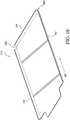
- FIG. 10 is a perspective view of an exemplary cover plate 310 of the exemplary moisture ingress controlling system 300.
- At least one slot 1000 is provided to the front edge 514 of the cover plate 310 to allow moisture trapped on top of the cover plate 310 to exit in a downslope 602 direction.
- the at least one slot 1000 is positioned on the cover plate 310 such that moisture exiting the at least one slot 1000 falls into an adjacent intercostal space, not the immediate space where the electrical connector 502 is affixed to the skin 210.
- the front edge 514 is curved upwardly in order to prevent moisture from falling off the cover plate 310 and into the immediate intercostal space.
- FIG. 11 is a flowchart 1100 of a method of controlling moisture ingress in aircraft skin mounted electronics using a moisture ingress control system 300.
- downslope 602 moisture flow is diverted (1102) around an electrical connector 502 using a shroud 302 of a moisture diverter 308 which forms an enclosure 606 around the electrical connector 502.
- Moisture which accumulates within the enclosure 606 is permitted (1104) to exit the enclosure through a slot 702 disposed in a downslope side of the shroud 302.
- upslope moisture flow is obstructed (1106) by the backflow gate 306, preventing the upslope flow from entering back into the slot 702.
- Vertically dripping moisture 608 is optionally prevented (1108) from dripping into the enclosure 606 by optionally removably attaching a cover plate 310 to the intercostals 504 on either side of the electrical connector 502.
- compositions, method or structure may include additional ingredients, steps and/or parts, but only if the additional ingredients, steps and/or parts do not materially alter the basic and novel characteristics of the claimed composition, method or structure.
- a compound or “at least one compound” may include a plurality of compounds, including mixtures thereof.
- range format is merely for convenience and brevity and should not be construed as an inflexible limitation on the scope of the disclosure. Accordingly, the description of a range should be considered to have specifically disclosed all the possible subranges as well as individual numerical values within that range. For example, description of a range such as from 1 to 6 should be considered to have specifically disclosed subranges such as from 1 to 3, from 1 to 4, from 1 to 5, from 2 to 4, from 2 to 6, from 3 to 6 etc., as well as individual numbers within that range, for example, 1, 2, 3, 4, 5, and 6. This applies regardless of the breadth of the range. Further, described ranges are intended to include numbers outside any range described within statistical error and/or inherent measurement equipment limitations.
Landscapes
- Engineering & Computer Science (AREA)
- Aviation & Aerospace Engineering (AREA)
- Mechanical Engineering (AREA)
- Casings For Electric Apparatus (AREA)
Applications Claiming Priority (1)
| Application Number | Priority Date | Filing Date | Title |
|---|---|---|---|
| US15/400,449 US10513323B2 (en) | 2017-01-06 | 2017-01-06 | Systems and methods for controlling moisture ingress in aircraft skin mounted electronics |
Publications (2)
| Publication Number | Publication Date |
|---|---|
| EP3345827A1 true EP3345827A1 (fr) | 2018-07-11 |
| EP3345827B1 EP3345827B1 (fr) | 2021-07-07 |
Family
ID=60450483
Family Applications (1)
| Application Number | Title | Priority Date | Filing Date |
|---|---|---|---|
| EP17203034.8A Active EP3345827B1 (fr) | 2017-01-06 | 2017-11-22 | Systèmes et procédés permettant de contrôler l'entrée de l'humidité dans l'électronique monté sur le revêtement d'un aéronef |
Country Status (4)
| Country | Link |
|---|---|
| US (1) | US10513323B2 (fr) |
| EP (1) | EP3345827B1 (fr) |
| JP (1) | JP7043244B2 (fr) |
| CN (1) | CN108275257B (fr) |
Families Citing this family (2)
| Publication number | Priority date | Publication date | Assignee | Title |
|---|---|---|---|---|
| US10513323B2 (en) * | 2017-01-06 | 2019-12-24 | The Boeing Company | Systems and methods for controlling moisture ingress in aircraft skin mounted electronics |
| US10988230B2 (en) * | 2017-06-19 | 2021-04-27 | The Boeing Company | Passive moisture management bladder in an aircraft |
Citations (9)
| Publication number | Priority date | Publication date | Assignee | Title |
|---|---|---|---|---|
| WO2002036426A2 (fr) * | 2000-08-18 | 2002-05-10 | Goodrich Corporation | Assemblage de drain profile d'aeroplane |
| US6538219B2 (en) * | 2000-12-13 | 2003-03-25 | Esw-Extel Systems Wedel Gesellschaft Fuer Ausruestung Mbh | Arrangement for detecting impermissibly high forces acting on the supporting structure of a vehicle |
| US20030221851A1 (en) * | 2002-05-28 | 2003-12-04 | Daniel Motzigkeit | Conduit channel for insulated conductor lines and devices of an in-flight entertainment system in an aircraft |
| US20070199188A1 (en) * | 2006-02-24 | 2007-08-30 | Barker David N | Door pod assembly |
| US20120222880A1 (en) * | 2011-03-04 | 2012-09-06 | Thomas & Betts International, Inc. | Water-resistant while-in-use electrical box |
| JP2013233012A (ja) * | 2012-04-27 | 2013-11-14 | Mirai Ind Co Ltd | 配線ボックス |
| US20140083734A1 (en) * | 2012-09-21 | 2014-03-27 | Thomas & Belts International, Inc. | Electrical box with drip point compartments |
| US20140182877A1 (en) * | 2012-12-28 | 2014-07-03 | Thomas & Betts International Llc | While-In-Use Cover with Splash Guards |
| WO2014135938A1 (fr) * | 2013-03-06 | 2014-09-12 | Bombardier Inc. | Système de drainage pour avion |
Family Cites Families (20)
| Publication number | Priority date | Publication date | Assignee | Title |
|---|---|---|---|---|
| US5290996A (en) * | 1992-02-21 | 1994-03-01 | The B. F. Goodrich Company | Modular drainmast for aircraft |
| JPH08180760A (ja) * | 1994-12-26 | 1996-07-12 | Oki Electric Ind Co Ltd | 防水機器用キーパッド |
| US20040175516A1 (en) * | 1998-10-28 | 2004-09-09 | Gerhard Schmitz | Insulating arrangement for the inner insulation of an aircraft |
| IT1308475B1 (it) * | 1999-05-07 | 2001-12-17 | Gate Spa | Motoventilatore, particolarmente per uno scambiatore di calore di unautoveicolo |
| US6776183B1 (en) * | 2003-02-28 | 2004-08-17 | Goodrich Corporation | Aircraft drain device |
| DE102004036296B4 (de) * | 2004-07-27 | 2010-04-01 | Airbus Deutschland Gmbh | Ablassvorrichtung für ein Flugzeug |
| US7731127B2 (en) * | 2005-05-18 | 2010-06-08 | Airbus Deutschland Gmbh | Drain mast connector |
| DE102006023209A1 (de) * | 2006-05-17 | 2007-11-22 | Airbus Deutschland Gmbh | Isolierung einer Flugzeugrumpfstruktur |
| DE102008037142B4 (de) * | 2008-08-08 | 2011-12-22 | Airbus Operations Gmbh | Ausfahrbarer Abweiser zum Freisetzen von Struktur schädigenden Fluiden |
| US20110121137A1 (en) * | 2009-11-24 | 2011-05-26 | Electrofilm Manufacturing Company Llc | Method and apparatus for directing waste away from aircraft |
| DE102010052671B4 (de) * | 2010-11-26 | 2017-03-23 | Airbus Operations Gmbh | Isolierungsanordnung mit Ventilationsöffnungen für Luftfahrzeuge |
| JP2013065788A (ja) * | 2011-09-20 | 2013-04-11 | Hitachi Cable Ltd | 水抜き構造 |
| FR2984846B1 (fr) * | 2011-12-21 | 2014-01-24 | Airbus Operations Sas | Dispositif d'isolation standardise pour aeronef et procedes de fabrication et d'utilisation de celui-ci |
| FR2994943B1 (fr) * | 2012-08-30 | 2014-09-12 | Turbomeca | Procede de vidange et collecteur de purge de circuit de carburation d'un helicoptere |
| JP5513569B2 (ja) * | 2012-09-03 | 2014-06-04 | ファナック株式会社 | 電子機器の防滴構造 |
| DE102012223332B4 (de) * | 2012-12-17 | 2016-07-28 | Continental Automotive Gmbh | Druckausgleichseinrichtung und Gehäusebauteil |
| US9758251B2 (en) * | 2013-03-15 | 2017-09-12 | United Airlines, Inc. | Aircraft emergency escape slide container and method of changing an aircraft emergency escape slide |
| US9653897B2 (en) * | 2014-11-25 | 2017-05-16 | The Wiremold Company | Outdoor electrical box |
| US10023286B2 (en) * | 2015-11-19 | 2018-07-17 | The Boeing Company | Aircraft bay blankets that provide enhanced drainage features |
| US10513323B2 (en) * | 2017-01-06 | 2019-12-24 | The Boeing Company | Systems and methods for controlling moisture ingress in aircraft skin mounted electronics |
-
2017
- 2017-01-06 US US15/400,449 patent/US10513323B2/en active Active
- 2017-11-22 EP EP17203034.8A patent/EP3345827B1/fr active Active
- 2017-12-20 JP JP2017243514A patent/JP7043244B2/ja active Active
- 2017-12-27 CN CN201711441139.XA patent/CN108275257B/zh active Active
Patent Citations (9)
| Publication number | Priority date | Publication date | Assignee | Title |
|---|---|---|---|---|
| WO2002036426A2 (fr) * | 2000-08-18 | 2002-05-10 | Goodrich Corporation | Assemblage de drain profile d'aeroplane |
| US6538219B2 (en) * | 2000-12-13 | 2003-03-25 | Esw-Extel Systems Wedel Gesellschaft Fuer Ausruestung Mbh | Arrangement for detecting impermissibly high forces acting on the supporting structure of a vehicle |
| US20030221851A1 (en) * | 2002-05-28 | 2003-12-04 | Daniel Motzigkeit | Conduit channel for insulated conductor lines and devices of an in-flight entertainment system in an aircraft |
| US20070199188A1 (en) * | 2006-02-24 | 2007-08-30 | Barker David N | Door pod assembly |
| US20120222880A1 (en) * | 2011-03-04 | 2012-09-06 | Thomas & Betts International, Inc. | Water-resistant while-in-use electrical box |
| JP2013233012A (ja) * | 2012-04-27 | 2013-11-14 | Mirai Ind Co Ltd | 配線ボックス |
| US20140083734A1 (en) * | 2012-09-21 | 2014-03-27 | Thomas & Belts International, Inc. | Electrical box with drip point compartments |
| US20140182877A1 (en) * | 2012-12-28 | 2014-07-03 | Thomas & Betts International Llc | While-In-Use Cover with Splash Guards |
| WO2014135938A1 (fr) * | 2013-03-06 | 2014-09-12 | Bombardier Inc. | Système de drainage pour avion |
Also Published As
| Publication number | Publication date |
|---|---|
| US20180194450A1 (en) | 2018-07-12 |
| CN108275257A (zh) | 2018-07-13 |
| JP2018140768A (ja) | 2018-09-13 |
| EP3345827B1 (fr) | 2021-07-07 |
| CN108275257B (zh) | 2023-05-30 |
| US10513323B2 (en) | 2019-12-24 |
| JP7043244B2 (ja) | 2022-03-29 |
Similar Documents
| Publication | Publication Date | Title |
|---|---|---|
| EP3170741B1 (fr) | Revêtements de compartiment d'aéronef ayant des caractéristiques de drainage améliorées | |
| US8727281B2 (en) | Condensed water decreasing insulation package for thermal and acoustic insulation of a vehicle cabin | |
| EP3348468B1 (fr) | Ensembles de bande de capuchon de couverture isolante et leurs procédés d'utilisation | |
| EP2202151A2 (fr) | Système de protection contre le givre pour avion | |
| US10513323B2 (en) | Systems and methods for controlling moisture ingress in aircraft skin mounted electronics | |
| EP3476713B1 (fr) | Dispositifs et procédés pour piéger l'humidité d'un élément structurel | |
| US20130009010A1 (en) | System for draining water condensation in an aircraft | |
| EP3290331B1 (fr) | Interdiction de chemin d'humidité et système d'isolation thermique ainsi que leur procédé d'assemblage | |
| EP2828150B1 (fr) | Dispositif pour fixer une structure d'aéronef | |
| CA2822630C (fr) | Systeme de protection cotre le givre | |
| EP3156322B1 (fr) | Isolation de cadre offrant des caractéristiques de drainage améliorées | |
| CN111452985B (zh) | 用于从交通工具内的空气中被动去除水分的系统和方法 | |
| EP2899127B1 (fr) | Système de déhumidification pour utilisation dans un véhicule et son procédé d'assemblage | |
| US10442518B2 (en) | Moisture diversion systems and methods of using same | |
| CN107054614B (zh) | 为飞行器排出水分的装置和方法 | |
| US8678318B2 (en) | Insulation arrangement in an aircraft | |
| US20120048413A1 (en) | Aircraft fuel tank vent | |
| US11548609B2 (en) | Moisture control systems and methods for controlling moisture in an aircraft | |
| US20130299011A1 (en) | Apparatus for the contamination-free drainage of clean water in an aircraft | |
| US20250058867A1 (en) | Insulation Blanket Assemblies and Methods |
Legal Events
| Date | Code | Title | Description |
|---|---|---|---|
| PUAI | Public reference made under article 153(3) epc to a published international application that has entered the european phase |
Free format text: ORIGINAL CODE: 0009012 |
|
| STAA | Information on the status of an ep patent application or granted ep patent |
Free format text: STATUS: REQUEST FOR EXAMINATION WAS MADE |
|
| 17P | Request for examination filed |
Effective date: 20171122 |
|
| AK | Designated contracting states |
Kind code of ref document: A1 Designated state(s): AL AT BE BG CH CY CZ DE DK EE ES FI FR GB GR HR HU IE IS IT LI LT LU LV MC MK MT NL NO PL PT RO RS SE SI SK SM TR |
|
| AX | Request for extension of the european patent |
Extension state: BA ME |
|
| STAA | Information on the status of an ep patent application or granted ep patent |
Free format text: STATUS: EXAMINATION IS IN PROGRESS |
|
| 17Q | First examination report despatched |
Effective date: 20200320 |
|
| GRAP | Despatch of communication of intention to grant a patent |
Free format text: ORIGINAL CODE: EPIDOSNIGR1 |
|
| STAA | Information on the status of an ep patent application or granted ep patent |
Free format text: STATUS: GRANT OF PATENT IS INTENDED |
|
| INTG | Intention to grant announced |
Effective date: 20210129 |
|
| GRAS | Grant fee paid |
Free format text: ORIGINAL CODE: EPIDOSNIGR3 |
|
| GRAA | (expected) grant |
Free format text: ORIGINAL CODE: 0009210 |
|
| STAA | Information on the status of an ep patent application or granted ep patent |
Free format text: STATUS: THE PATENT HAS BEEN GRANTED |
|
| AK | Designated contracting states |
Kind code of ref document: B1 Designated state(s): AL AT BE BG CH CY CZ DE DK EE ES FI FR GB GR HR HU IE IS IT LI LT LU LV MC MK MT NL NO PL PT RO RS SE SI SK SM TR |
|
| REG | Reference to a national code |
Ref country code: GB Ref legal event code: FG4D |
|
| REG | Reference to a national code |
Ref country code: AT Ref legal event code: REF Ref document number: 1408360 Country of ref document: AT Kind code of ref document: T Effective date: 20210715 |
|
| REG | Reference to a national code |
Ref country code: DE Ref legal event code: R096 Ref document number: 602017041559 Country of ref document: DE |
|
| REG | Reference to a national code |
Ref country code: IE Ref legal event code: FG4D |
|
| REG | Reference to a national code |
Ref country code: LT Ref legal event code: MG9D |
|
| REG | Reference to a national code |
Ref country code: NL Ref legal event code: MP Effective date: 20210707 |
|
| REG | Reference to a national code |
Ref country code: AT Ref legal event code: MK05 Ref document number: 1408360 Country of ref document: AT Kind code of ref document: T Effective date: 20210707 |
|
| PG25 | Lapsed in a contracting state [announced via postgrant information from national office to epo] |
Ref country code: PT Free format text: LAPSE BECAUSE OF FAILURE TO SUBMIT A TRANSLATION OF THE DESCRIPTION OR TO PAY THE FEE WITHIN THE PRESCRIBED TIME-LIMIT Effective date: 20211108 Ref country code: NL Free format text: LAPSE BECAUSE OF FAILURE TO SUBMIT A TRANSLATION OF THE DESCRIPTION OR TO PAY THE FEE WITHIN THE PRESCRIBED TIME-LIMIT Effective date: 20210707 Ref country code: NO Free format text: LAPSE BECAUSE OF FAILURE TO SUBMIT A TRANSLATION OF THE DESCRIPTION OR TO PAY THE FEE WITHIN THE PRESCRIBED TIME-LIMIT Effective date: 20211007 Ref country code: ES Free format text: LAPSE BECAUSE OF FAILURE TO SUBMIT A TRANSLATION OF THE DESCRIPTION OR TO PAY THE FEE WITHIN THE PRESCRIBED TIME-LIMIT Effective date: 20210707 Ref country code: FI Free format text: LAPSE BECAUSE OF FAILURE TO SUBMIT A TRANSLATION OF THE DESCRIPTION OR TO PAY THE FEE WITHIN THE PRESCRIBED TIME-LIMIT Effective date: 20210707 Ref country code: BG Free format text: LAPSE BECAUSE OF FAILURE TO SUBMIT A TRANSLATION OF THE DESCRIPTION OR TO PAY THE FEE WITHIN THE PRESCRIBED TIME-LIMIT Effective date: 20211007 Ref country code: AT Free format text: LAPSE BECAUSE OF FAILURE TO SUBMIT A TRANSLATION OF THE DESCRIPTION OR TO PAY THE FEE WITHIN THE PRESCRIBED TIME-LIMIT Effective date: 20210707 Ref country code: LT Free format text: LAPSE BECAUSE OF FAILURE TO SUBMIT A TRANSLATION OF THE DESCRIPTION OR TO PAY THE FEE WITHIN THE PRESCRIBED TIME-LIMIT Effective date: 20210707 Ref country code: SE Free format text: LAPSE BECAUSE OF FAILURE TO SUBMIT A TRANSLATION OF THE DESCRIPTION OR TO PAY THE FEE WITHIN THE PRESCRIBED TIME-LIMIT Effective date: 20210707 Ref country code: RS Free format text: LAPSE BECAUSE OF FAILURE TO SUBMIT A TRANSLATION OF THE DESCRIPTION OR TO PAY THE FEE WITHIN THE PRESCRIBED TIME-LIMIT Effective date: 20210707 Ref country code: HR Free format text: LAPSE BECAUSE OF FAILURE TO SUBMIT A TRANSLATION OF THE DESCRIPTION OR TO PAY THE FEE WITHIN THE PRESCRIBED TIME-LIMIT Effective date: 20210707 |
|
| PG25 | Lapsed in a contracting state [announced via postgrant information from national office to epo] |
Ref country code: PL Free format text: LAPSE BECAUSE OF FAILURE TO SUBMIT A TRANSLATION OF THE DESCRIPTION OR TO PAY THE FEE WITHIN THE PRESCRIBED TIME-LIMIT Effective date: 20210707 Ref country code: LV Free format text: LAPSE BECAUSE OF FAILURE TO SUBMIT A TRANSLATION OF THE DESCRIPTION OR TO PAY THE FEE WITHIN THE PRESCRIBED TIME-LIMIT Effective date: 20210707 Ref country code: GR Free format text: LAPSE BECAUSE OF FAILURE TO SUBMIT A TRANSLATION OF THE DESCRIPTION OR TO PAY THE FEE WITHIN THE PRESCRIBED TIME-LIMIT Effective date: 20211008 |
|
| REG | Reference to a national code |
Ref country code: DE Ref legal event code: R097 Ref document number: 602017041559 Country of ref document: DE |
|
| PG25 | Lapsed in a contracting state [announced via postgrant information from national office to epo] |
Ref country code: DK Free format text: LAPSE BECAUSE OF FAILURE TO SUBMIT A TRANSLATION OF THE DESCRIPTION OR TO PAY THE FEE WITHIN THE PRESCRIBED TIME-LIMIT Effective date: 20210707 |
|
| PLBE | No opposition filed within time limit |
Free format text: ORIGINAL CODE: 0009261 |
|
| STAA | Information on the status of an ep patent application or granted ep patent |
Free format text: STATUS: NO OPPOSITION FILED WITHIN TIME LIMIT |
|
| PG25 | Lapsed in a contracting state [announced via postgrant information from national office to epo] |
Ref country code: SM Free format text: LAPSE BECAUSE OF FAILURE TO SUBMIT A TRANSLATION OF THE DESCRIPTION OR TO PAY THE FEE WITHIN THE PRESCRIBED TIME-LIMIT Effective date: 20210707 Ref country code: SK Free format text: LAPSE BECAUSE OF FAILURE TO SUBMIT A TRANSLATION OF THE DESCRIPTION OR TO PAY THE FEE WITHIN THE PRESCRIBED TIME-LIMIT Effective date: 20210707 Ref country code: RO Free format text: LAPSE BECAUSE OF FAILURE TO SUBMIT A TRANSLATION OF THE DESCRIPTION OR TO PAY THE FEE WITHIN THE PRESCRIBED TIME-LIMIT Effective date: 20210707 Ref country code: EE Free format text: LAPSE BECAUSE OF FAILURE TO SUBMIT A TRANSLATION OF THE DESCRIPTION OR TO PAY THE FEE WITHIN THE PRESCRIBED TIME-LIMIT Effective date: 20210707 Ref country code: CZ Free format text: LAPSE BECAUSE OF FAILURE TO SUBMIT A TRANSLATION OF THE DESCRIPTION OR TO PAY THE FEE WITHIN THE PRESCRIBED TIME-LIMIT Effective date: 20210707 Ref country code: AL Free format text: LAPSE BECAUSE OF FAILURE TO SUBMIT A TRANSLATION OF THE DESCRIPTION OR TO PAY THE FEE WITHIN THE PRESCRIBED TIME-LIMIT Effective date: 20210707 |
|
| 26N | No opposition filed |
Effective date: 20220408 |
|
| PG25 | Lapsed in a contracting state [announced via postgrant information from national office to epo] |
Ref country code: MC Free format text: LAPSE BECAUSE OF FAILURE TO SUBMIT A TRANSLATION OF THE DESCRIPTION OR TO PAY THE FEE WITHIN THE PRESCRIBED TIME-LIMIT Effective date: 20210707 |
|
| REG | Reference to a national code |
Ref country code: CH Ref legal event code: PL |
|
| PG25 | Lapsed in a contracting state [announced via postgrant information from national office to epo] |
Ref country code: LU Free format text: LAPSE BECAUSE OF NON-PAYMENT OF DUE FEES Effective date: 20211122 Ref country code: IT Free format text: LAPSE BECAUSE OF FAILURE TO SUBMIT A TRANSLATION OF THE DESCRIPTION OR TO PAY THE FEE WITHIN THE PRESCRIBED TIME-LIMIT Effective date: 20210707 Ref country code: BE Free format text: LAPSE BECAUSE OF NON-PAYMENT OF DUE FEES Effective date: 20211130 |
|
| REG | Reference to a national code |
Ref country code: BE Ref legal event code: MM Effective date: 20211130 |
|
| PG25 | Lapsed in a contracting state [announced via postgrant information from national office to epo] |
Ref country code: LI Free format text: LAPSE BECAUSE OF NON-PAYMENT OF DUE FEES Effective date: 20211130 Ref country code: CH Free format text: LAPSE BECAUSE OF NON-PAYMENT OF DUE FEES Effective date: 20211130 |
|
| PG25 | Lapsed in a contracting state [announced via postgrant information from national office to epo] |
Ref country code: IE Free format text: LAPSE BECAUSE OF NON-PAYMENT OF DUE FEES Effective date: 20211122 |
|
| PG25 | Lapsed in a contracting state [announced via postgrant information from national office to epo] |
Ref country code: HU Free format text: LAPSE BECAUSE OF FAILURE TO SUBMIT A TRANSLATION OF THE DESCRIPTION OR TO PAY THE FEE WITHIN THE PRESCRIBED TIME-LIMIT; INVALID AB INITIO Effective date: 20171122 |
|
| P01 | Opt-out of the competence of the unified patent court (upc) registered |
Effective date: 20230516 |
|
| PG25 | Lapsed in a contracting state [announced via postgrant information from national office to epo] |
Ref country code: CY Free format text: LAPSE BECAUSE OF FAILURE TO SUBMIT A TRANSLATION OF THE DESCRIPTION OR TO PAY THE FEE WITHIN THE PRESCRIBED TIME-LIMIT Effective date: 20210707 |
|
| PG25 | Lapsed in a contracting state [announced via postgrant information from national office to epo] |
Ref country code: MK Free format text: LAPSE BECAUSE OF FAILURE TO SUBMIT A TRANSLATION OF THE DESCRIPTION OR TO PAY THE FEE WITHIN THE PRESCRIBED TIME-LIMIT Effective date: 20210707 |
|
| PG25 | Lapsed in a contracting state [announced via postgrant information from national office to epo] |
Ref country code: TR Free format text: LAPSE BECAUSE OF FAILURE TO SUBMIT A TRANSLATION OF THE DESCRIPTION OR TO PAY THE FEE WITHIN THE PRESCRIBED TIME-LIMIT Effective date: 20210707 |
|
| PG25 | Lapsed in a contracting state [announced via postgrant information from national office to epo] |
Ref country code: MT Free format text: LAPSE BECAUSE OF FAILURE TO SUBMIT A TRANSLATION OF THE DESCRIPTION OR TO PAY THE FEE WITHIN THE PRESCRIBED TIME-LIMIT Effective date: 20210707 |
|
| PGFP | Annual fee paid to national office [announced via postgrant information from national office to epo] |
Ref country code: DE Payment date: 20251128 Year of fee payment: 9 |
|
| PGFP | Annual fee paid to national office [announced via postgrant information from national office to epo] |
Ref country code: GB Payment date: 20251127 Year of fee payment: 9 |
|
| PGFP | Annual fee paid to national office [announced via postgrant information from national office to epo] |
Ref country code: FR Payment date: 20251125 Year of fee payment: 9 |