EP3346029A1 - Grain abrasif plaqué par impulsion - Google Patents
Grain abrasif plaqué par impulsion Download PDFInfo
- Publication number
- EP3346029A1 EP3346029A1 EP18150744.3A EP18150744A EP3346029A1 EP 3346029 A1 EP3346029 A1 EP 3346029A1 EP 18150744 A EP18150744 A EP 18150744A EP 3346029 A1 EP3346029 A1 EP 3346029A1
- Authority
- EP
- European Patent Office
- Prior art keywords
- abrasive grit
- recited
- nickel
- plating
- matrix material
- Prior art date
- Legal status (The legal status is an assumption and is not a legal conclusion. Google has not performed a legal analysis and makes no representation as to the accuracy of the status listed.)
- Granted
Links
Images





Classifications
-
- C—CHEMISTRY; METALLURGY
- C25—ELECTROLYTIC OR ELECTROPHORETIC PROCESSES; APPARATUS THEREFOR
- C25D—PROCESSES FOR THE ELECTROLYTIC OR ELECTROPHORETIC PRODUCTION OF COATINGS; ELECTROFORMING; APPARATUS THEREFOR
- C25D5/00—Electroplating characterised by the process; Pretreatment or after-treatment of workpieces
- C25D5/18—Electroplating using modulated, pulsed or reversing current
-
- C—CHEMISTRY; METALLURGY
- C25—ELECTROLYTIC OR ELECTROPHORETIC PROCESSES; APPARATUS THEREFOR
- C25D—PROCESSES FOR THE ELECTROLYTIC OR ELECTROPHORETIC PRODUCTION OF COATINGS; ELECTROFORMING; APPARATUS THEREFOR
- C25D7/00—Electroplating characterised by the article coated
-
- C—CHEMISTRY; METALLURGY
- C25—ELECTROLYTIC OR ELECTROPHORETIC PROCESSES; APPARATUS THEREFOR
- C25D—PROCESSES FOR THE ELECTROLYTIC OR ELECTROPHORETIC PRODUCTION OF COATINGS; ELECTROFORMING; APPARATUS THEREFOR
- C25D15/00—Electrolytic or electrophoretic production of coatings containing embedded materials, e.g. particles, whiskers, wires
-
- C—CHEMISTRY; METALLURGY
- C25—ELECTROLYTIC OR ELECTROPHORETIC PROCESSES; APPARATUS THEREFOR
- C25D—PROCESSES FOR THE ELECTROLYTIC OR ELECTROPHORETIC PRODUCTION OF COATINGS; ELECTROFORMING; APPARATUS THEREFOR
- C25D15/00—Electrolytic or electrophoretic production of coatings containing embedded materials, e.g. particles, whiskers, wires
- C25D15/02—Combined electrolytic and electrophoretic processes with charged materials
-
- C—CHEMISTRY; METALLURGY
- C25—ELECTROLYTIC OR ELECTROPHORETIC PROCESSES; APPARATUS THEREFOR
- C25D—PROCESSES FOR THE ELECTROLYTIC OR ELECTROPHORETIC PRODUCTION OF COATINGS; ELECTROFORMING; APPARATUS THEREFOR
- C25D5/00—Electroplating characterised by the process; Pretreatment or after-treatment of workpieces
- C25D5/34—Pretreatment of metallic surfaces to be electroplated
-
- C—CHEMISTRY; METALLURGY
- C25—ELECTROLYTIC OR ELECTROPHORETIC PROCESSES; APPARATUS THEREFOR
- C25D—PROCESSES FOR THE ELECTROLYTIC OR ELECTROPHORETIC PRODUCTION OF COATINGS; ELECTROFORMING; APPARATUS THEREFOR
- C25D5/00—Electroplating characterised by the process; Pretreatment or after-treatment of workpieces
- C25D5/48—After-treatment of electroplated surfaces
- C25D5/50—After-treatment of electroplated surfaces by heat-treatment
-
- C—CHEMISTRY; METALLURGY
- C25—ELECTROLYTIC OR ELECTROPHORETIC PROCESSES; APPARATUS THEREFOR
- C25D—PROCESSES FOR THE ELECTROLYTIC OR ELECTROPHORETIC PRODUCTION OF COATINGS; ELECTROFORMING; APPARATUS THEREFOR
- C25D5/00—Electroplating characterised by the process; Pretreatment or after-treatment of workpieces
- C25D5/60—Electroplating characterised by the structure or texture of the layers
- C25D5/615—Microstructure of the layers, e.g. mixed structure
- C25D5/617—Crystalline layers
-
- C—CHEMISTRY; METALLURGY
- C25—ELECTROLYTIC OR ELECTROPHORETIC PROCESSES; APPARATUS THEREFOR
- C25D—PROCESSES FOR THE ELECTROLYTIC OR ELECTROPHORETIC PRODUCTION OF COATINGS; ELECTROFORMING; APPARATUS THEREFOR
- C25D5/00—Electroplating characterised by the process; Pretreatment or after-treatment of workpieces
- C25D5/60—Electroplating characterised by the structure or texture of the layers
- C25D5/623—Porosity of the layers
-
- F—MECHANICAL ENGINEERING; LIGHTING; HEATING; WEAPONS; BLASTING
- F01—MACHINES OR ENGINES IN GENERAL; ENGINE PLANTS IN GENERAL; STEAM ENGINES
- F01D—NON-POSITIVE DISPLACEMENT MACHINES OR ENGINES, e.g. STEAM TURBINES
- F01D11/00—Preventing or minimising internal leakage of working-fluid, e.g. between stages
- F01D11/08—Preventing or minimising internal leakage of working-fluid, e.g. between stages for sealing space between rotor blade tips and stator
- F01D11/12—Preventing or minimising internal leakage of working-fluid, e.g. between stages for sealing space between rotor blade tips and stator using a rubstrip, e.g. erodible. deformable or resiliently-biased part
- F01D11/122—Preventing or minimising internal leakage of working-fluid, e.g. between stages for sealing space between rotor blade tips and stator using a rubstrip, e.g. erodible. deformable or resiliently-biased part with erodable or abradable material
-
- F—MECHANICAL ENGINEERING; LIGHTING; HEATING; WEAPONS; BLASTING
- F01—MACHINES OR ENGINES IN GENERAL; ENGINE PLANTS IN GENERAL; STEAM ENGINES
- F01D—NON-POSITIVE DISPLACEMENT MACHINES OR ENGINES, e.g. STEAM TURBINES
- F01D5/00—Blades; Blade-carrying members; Heating, heat-insulating, cooling or antivibration means on the blades or the members
- F01D5/12—Blades
- F01D5/14—Form or construction
- F01D5/147—Construction, i.e. structural features, e.g. of weight-saving hollow blades
-
- F—MECHANICAL ENGINEERING; LIGHTING; HEATING; WEAPONS; BLASTING
- F01—MACHINES OR ENGINES IN GENERAL; ENGINE PLANTS IN GENERAL; STEAM ENGINES
- F01D—NON-POSITIVE DISPLACEMENT MACHINES OR ENGINES, e.g. STEAM TURBINES
- F01D5/00—Blades; Blade-carrying members; Heating, heat-insulating, cooling or antivibration means on the blades or the members
- F01D5/12—Blades
- F01D5/28—Selecting particular materials; Particular measures relating thereto; Measures against erosion or corrosion
- F01D5/288—Protective coatings for blades
-
- C—CHEMISTRY; METALLURGY
- C25—ELECTROLYTIC OR ELECTROPHORETIC PROCESSES; APPARATUS THEREFOR
- C25D—PROCESSES FOR THE ELECTROLYTIC OR ELECTROPHORETIC PRODUCTION OF COATINGS; ELECTROFORMING; APPARATUS THEREFOR
- C25D5/00—Electroplating characterised by the process; Pretreatment or after-treatment of workpieces
- C25D5/10—Electroplating with more than one layer of the same or of different metals
- C25D5/12—Electroplating with more than one layer of the same or of different metals at least one layer being of nickel or chromium
- C25D5/14—Electroplating with more than one layer of the same or of different metals at least one layer being of nickel or chromium two or more layers being of nickel or chromium, e.g. duplex or triplex layers
-
- F—MECHANICAL ENGINEERING; LIGHTING; HEATING; WEAPONS; BLASTING
- F05—INDEXING SCHEMES RELATING TO ENGINES OR PUMPS IN VARIOUS SUBCLASSES OF CLASSES F01-F04
- F05D—INDEXING SCHEME FOR ASPECTS RELATING TO NON-POSITIVE-DISPLACEMENT MACHINES OR ENGINES, GAS-TURBINES OR JET-PROPULSION PLANTS
- F05D2220/00—Application
- F05D2220/30—Application in turbines
- F05D2220/32—Application in turbines in gas turbines
-
- F—MECHANICAL ENGINEERING; LIGHTING; HEATING; WEAPONS; BLASTING
- F05—INDEXING SCHEMES RELATING TO ENGINES OR PUMPS IN VARIOUS SUBCLASSES OF CLASSES F01-F04
- F05D—INDEXING SCHEME FOR ASPECTS RELATING TO NON-POSITIVE-DISPLACEMENT MACHINES OR ENGINES, GAS-TURBINES OR JET-PROPULSION PLANTS
- F05D2230/00—Manufacture
- F05D2230/30—Manufacture with deposition of material
- F05D2230/31—Layer deposition
-
- F—MECHANICAL ENGINEERING; LIGHTING; HEATING; WEAPONS; BLASTING
- F05—INDEXING SCHEMES RELATING TO ENGINES OR PUMPS IN VARIOUS SUBCLASSES OF CLASSES F01-F04
- F05D—INDEXING SCHEME FOR ASPECTS RELATING TO NON-POSITIVE-DISPLACEMENT MACHINES OR ENGINES, GAS-TURBINES OR JET-PROPULSION PLANTS
- F05D2240/00—Components
- F05D2240/20—Rotors
- F05D2240/30—Characteristics of rotor blades, i.e. of any element transforming dynamic fluid energy to or from rotational energy and being attached to a rotor
- F05D2240/307—Characteristics of rotor blades, i.e. of any element transforming dynamic fluid energy to or from rotational energy and being attached to a rotor related to the tip of a rotor blade
-
- F—MECHANICAL ENGINEERING; LIGHTING; HEATING; WEAPONS; BLASTING
- F05—INDEXING SCHEMES RELATING TO ENGINES OR PUMPS IN VARIOUS SUBCLASSES OF CLASSES F01-F04
- F05D—INDEXING SCHEME FOR ASPECTS RELATING TO NON-POSITIVE-DISPLACEMENT MACHINES OR ENGINES, GAS-TURBINES OR JET-PROPULSION PLANTS
- F05D2240/00—Components
- F05D2240/20—Rotors
- F05D2240/30—Characteristics of rotor blades, i.e. of any element transforming dynamic fluid energy to or from rotational energy and being attached to a rotor
- F05D2240/31—Characteristics of rotor blades, i.e. of any element transforming dynamic fluid energy to or from rotational energy and being attached to a rotor with roughened surfaces
-
- F—MECHANICAL ENGINEERING; LIGHTING; HEATING; WEAPONS; BLASTING
- F05—INDEXING SCHEMES RELATING TO ENGINES OR PUMPS IN VARIOUS SUBCLASSES OF CLASSES F01-F04
- F05D—INDEXING SCHEME FOR ASPECTS RELATING TO NON-POSITIVE-DISPLACEMENT MACHINES OR ENGINES, GAS-TURBINES OR JET-PROPULSION PLANTS
- F05D2300/00—Materials; Properties thereof
- F05D2300/20—Oxide or non-oxide ceramics
- F05D2300/22—Non-oxide ceramics
- F05D2300/228—Nitrides
- F05D2300/2282—Nitrides of boron
-
- F—MECHANICAL ENGINEERING; LIGHTING; HEATING; WEAPONS; BLASTING
- F05—INDEXING SCHEMES RELATING TO ENGINES OR PUMPS IN VARIOUS SUBCLASSES OF CLASSES F01-F04
- F05D—INDEXING SCHEME FOR ASPECTS RELATING TO NON-POSITIVE-DISPLACEMENT MACHINES OR ENGINES, GAS-TURBINES OR JET-PROPULSION PLANTS
- F05D2300/00—Materials; Properties thereof
- F05D2300/60—Properties or characteristics given to material by treatment or manufacturing
- F05D2300/603—Composites; e.g. fibre-reinforced
- F05D2300/6032—Metal matrix composites [MMC]
Definitions
- the present disclosure relates to a method for applying electroplated coatings, and more specifically to a method for applying abrasive grit to gas turbine airfoil blade tips via pulse plating.
- a gas turbine blade tip includes a coating with abrasive particles embedded in a matrix, the tip being intended to run against the surface of a shroud of a material which is softer than the abrasive particles.
- the codeposition of matrix material and particles is typically accomplished from an electrodeposition bath in which there are suspended abrasive particles formed from aluminum oxide, cubic boron nitride (CBN), or other abrasive carbides, oxides, silicides, or nitrides.
- the electrolytic application of the CBN abrasive may result in a fatigue life reduction to allow the airfoils to withstand interactions with abradable air seals, but could benefit from increased wear resistance and fatigue strengthening.
- the invention provides a method for forming an abrasive surface that includes applying an electric current through a plating solution so as to cause an abrasive grit to be deposited onto a workpiece; and varying a waveform of the electric current while building up a matrix material at least partially around the abrasive grit.
- An embodiment of the present disclosure may include that the abrasive grit includes cubic boron nitride (CBN).
- CBN cubic boron nitride
- a further embodiment of the present disclosure may include that varying the waveform includes pulse reverse current plating.
- a further embodiment of the present disclosure may include building up the matrix material around the abrasive grit with pulsed current nickel plating.
- a further embodiment of the present disclosure may include that building up the matrix material around the abrasive grit includes building up a nickel layer.
- a further embodiment of the present disclosure may include performing a bake for stress relief subsequent to building up the matrix material around the abrasive grit.
- a further embodiment of the present disclosure may include that varying the waveform of the electric current includes pulsing of the electric current to cause new nucleation of nickel crystals.
- a further embodiment of the present disclosure may include that the workpiece is a rotor blade.
- a further embodiment of the present disclosure may include that the workpiece is a tip of a rotor blade.
- the invention also provides a method for forming an abrasive surface that includes pulse plating a workpiece to build up a matrix material around an abrasive grit.
- a further embodiment of the present disclosure may include that the abrasive grit includes cubic boron nitride (CBN).
- CBN cubic boron nitride
- a further embodiment of the present disclosure may include that the pulse plating causes new nucleation of nickel crystals.
- a further embodiment of the present disclosure may include that the pulse plating includes tacking on the abrasive grit.
- a further embodiment of the present disclosure may include that the pulse plating includes building up a nickel layer as the matrix material around the abrasive grit.
- a further embodiment of the present disclosure may include performing a bake for stress relief subsequent to building up the matrix material around the abrasive grit.
- the invention also provides a rotor blade that includes an abrader that includes an abrasive grit with a grain size between 10-100 nm and a hardness between 250-400HV.
- a further embodiment of the present disclosure may include that rotor blade is a turbine blade.
- a further embodiment of the present disclosure may include that the abrader is applied to a tip of the rotor blade.
- a further embodiment of the present disclosure may include that the abrasive grit includes cubic boron nitride (CBN) that is pulse plated on the tip of the rotor blade.
- CBN cubic boron nitride
- FIG. 1 schematically illustrates a gas turbine engine 20.
- the gas turbine engine 20 is disclosed herein as a two-spool turbo fan that generally incorporates a fan section 22, a compressor section 24, a combustor section 26 and a turbine section 28.
- the fan section 22 drives air along a bypass flowpath while the compressor section 24 drives air along a core flowpath for compression and communication into the combustor section 26 then expansion through the turbine section 28.
- turbofan depicted as a turbofan in the disclosed non-limiting embodiment, the concepts described herein are not limited to use with turbofans as the teachings may be applied to other types of turbine engine architectures such as turbojets, turboshafts, and three-spool (plus fan) turbofans.
- the engine 20 generally includes a low spool 30 and a high spool 32 mounted for rotation about an engine central longitudinal axis A relative to an engine static structure 36 via several bearing structures 38.
- the low spool 30 generally includes an inner shaft 40 that interconnects a fan 42, a low pressure compressor (LPC) 44 and a low pressure turbine (“LPT”) 46.
- the inner shaft 40 drives the fan 42 directly or through a geared architecture 48 to drive the fan 42 at a lower speed than the low spool 30.
- An exemplary reduction transmission is an epicyclic transmission, namely a planetary or star gear system.
- the high spool 32 includes an outer shaft 50 that interconnects a high pressure compressor (HPC) 52 and high pressure turbine (HPT) 54.
- a combustor 56 is arranged between the HPC 52 and the HPT 54.
- the inner shaft 40 and the outer shaft 50 are concentric and rotate about the engine central longitudinal axis A.
- the main engine shafts 40, 50 are supported at a plurality of points by bearing structures 38 within the static structure 36.
- Various bearing structures 38 at various locations may alternatively or additionally be provided.
- a full ring shroud assembly 60 within the engine case structure 36 supports a blade outer air seal (BOAS) assembly 62 with a multiple of circumferentially distributed BOAS segments 64 proximate to a rotor assembly 66 (one segment schematically shown).
- BOAS blade outer air seal
- the full ring shroud assembly 60 and the BOAS assembly 62 are axially disposed between a forward stationary vane ring 68 and an aft stationary vane ring 70.
- Each vane ring 68, 70 include an array of vanes 72, 74 that extend between a respective inner vane platform 76, 78 and an outer vane platform 80, 82.
- the outer vane platforms 80, 82 are attached to the engine case structure 36.
- the rotor assembly 66 includes an array of blades 84 circumferentially disposed around a disk 86.
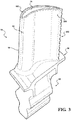
- Each blade 84 includes a root 88, a platform 90 and an airfoil 92 (also shown in FIG. 3 ).
- the blade roots 88 are received within a rim 94 of the disk 86 and the airfoils 92 extend radially outward such that a tip 96 of each airfoil 92 is closest to the blade outer air seal (BOAS) assembly 62.
- the platform 90 separates a gas path side inclusive of the airfoil 92 and a non-gas path side inclusive of the root 88.
- the platform 90 generally separates the root 88 and the airfoil 92 to define an inner boundary of a gas path.
- the airfoil 92 defines a blade chord between a leading edge 98, which may include various forward and/or aft sweep configurations, and a trailing edge 100.
- a first sidewall 102 that may be convex to define a suction side, and a second sidewall 104 that may be concave to define a pressure side are joined at the leading edge 98 and at the axially spaced trailing edge 100.
- the tip 96 extends between the sidewalls 102, 104 opposite the platform 90.
- the abrader 400 will rub against the abradable outside air seal and the abrader 400 will thus have a compositions based on, for example, whether the airfoil is used in the cold section, e.g., compressor, or the hot section, e.g., the turbine.
- application is not limited to aerospace components and various other workpieces for various grinding and/or polishing applications will benefit herefrom.
- the method 300 is herein directed to tipping blades in the cold section and need not specifically utilize Ni/Co-Cr-Al-Y/Hf powder or a nickel and/or cobalt (Ni/Co) matrix.
- the Cr-Al-Y/Hf powder refers to a mixture of chromium, aluminum, yttrium and/or hafnium elements in powder forms that are added into the bath ( FIGS. 7 and 8 ).
- the powder may alternatively be referred to as CrAlX, where X is yttrium, hafnium, and / or silicon.
- the final matrix after diffusion heat treat may alternatively be referred to as NiCoCrAlX, where X is yttrium, hafnium, and / or silicon.
- the agitation of the plating bath causes the powder to land on the blade tip 96.
- One example metal is a nickel / cobalt combination.
- the nickel / cobalt combination is plated at the same time that the Cr-Al-Y/Hf powder is landing on the blade tip, causing the powder to be encapsulated within the plating.
- what's left is a matrix 411 surrounding the abrasive grit 412, including the nickel/cobalt metal dispersed with Cr-Al-Y/Hf powder.
- the coating is diffusion heat treated, causing the Cr-Al-Y/Hf powder to diffuse into the nickel/cobalt forming a homogenous Ni-Co-Cr-Al-Y/Hf matrix around the abrasive grit 412.
- Pulse plating can be applied to Ni/Co-Cr-Al-Y/Hf powder or a Ni/Co matrix as well as for the high temperature capability requirements in the hot section as this coating may utilize a Ni/Co-Cr-Al-Y/Hf powder which is pulse plated into the Ni/Co matrix then heat treated to diffuse the Ni/Co-Cr-Al-Y/Hf into the Ni/Co matrix.
- the abrader 400 may include a nickel or a nickel-cobalt layer within which is disposed the abrasive grit 412 such as cubic boron nitride (CBN).
- the nickel or the nickel-cobalt is essentially the matrix 411 in which the abrasive grit 412 is disposed.
- the abrader 400 may include a nickel or a nickel-cobalt layer that contains the abrasive grit 412 in addition to a Ni/Co-Cr-Al-Y/Hf powder, then be heat treated to diffuse the Ni/Co-Cr-Al-Y/Hf into the nickel or a nickel-cobalt layer.
- Pulse plating ( FIG. 5B ) and/or pulse reverse plating ( FIG. 5C ) can be utilized in steps 310, 312, and 314, of the method 300 to increase the strength and hardness of the nickel matrix. Pulse plating involves rapidly turning the current on and off. In pulse reverse plating, not only is the current turned off for a short period of time, it is also reversed for a portion of the time ( FIG. 5C ). This has the effect of repeatedly depositing then removing small amounts of the material in a repetitive fashion.
- FIG. 5A graphically depicts an electrical current versus time plot for constant current plating.
- FIG. 5B and 5C respectively depict the electric current versus time plot for pulse plating and pulse reverse plating.
- pulse plating the current is turned on and off, and/or can be turned on for a period of time and then reversed for a period of time.
- Pulse reverse plating can alternatively or additionally be utilized to facilitate a desired surface finish and/or coating leveling, which refers to a coating's ability to have even distribution over the surface. Electric current is applied during this build-up step while the waveform is varied.
- a variety of wave forms e.g., ramp, step, sinusoidal, etc., may be utilized to rapidly turn off and on the current supply, such that pulsed current plating is effectuated. This builds up the nickel layer matrix 411 around the abrasive grit 412.
- Pulsing the current supply causes new nucleation of nickel crystals every time the current is turned on, resulting in a relatively finer grain size, and lower coating porosity.
- Pulse plating is operable to increase the strength of the nickel or nickel-cobalt matrix.
- the hardness and fatigue of the abrader 400 produced by the pulse plating method 300 is greater than the hardness and fatigue of the abrader 400 produced by other plating methods that do not involve pulse plating.
- This increase in hardness and fatigue resistance is primarily due to the reduced grain size of the nickel or nickel-cobalt matrix that occurs during pulse plating as compared with the grain size produced in a matrix having an identical chemical composition during the constant current process ( FIG. 5A ).
- pulse plating can form grains between 10 nanometers and 100 micrometers (the size of direct current plated nickel grains), although in the method 300, particular advantages to reduce coating porosity and increased hardness may arise generally in the 30 to 100 nanometer grain size range.
- the workpiece is cleaned (Step 302) in preparation for the pulse plating operations.
- the workpiece such as the tip 96, may be vapor blasted or otherwise cleaned.
- the tip 96 may then be etched (Step 304). This may be performed via any suitable etching technique.
- the etchant used in the anodic etching operation may include hydrochloric acid solution etching solution.
- An acid dip may then also be performed (Step 306).
- Various barriers or masks may then be utilized to facilitate containment of the applied electrolytic nickel strike/flash layer 402 ( FIG. 6 ).
- the strike/flash layer 402 in one example may be between about 0.00005 - 0.001 inches (0.00127 - 0.00254 mm) thick.
- the strike/flash layer 402 may be formed via a plating solution 704 that contains a matrix material 411 such as nickel or cobalt to be plated onto the tip 96.
- the plating solution utilizes a nickel sulfamate plating bath to apply a pure nickel base layer.
- the strike/flash layer 402 may, in one example, use a nickel chloride - hydrochloric acid solution that forms the initial bonding layer of nickel plating to the nickel alloy substrate of the example tip 96.
- the strike/flash layer 402 is a relatively thin layer whose function is to reduce imperfections in the surface of the tip 96.
- the tip 96 may be plated in a pulse plating process for a total time period of 1 minute to 10 minutes, or more specifically 2 to 5 minutes.
- the strike/flash layer 402 detailed herein includes nickel, the strike/flash layer 402 may also include a combination of nickel and cobalt.
- the strike/flash layer 402 forms a very strong bond with other nickel plating, and this layer ensures that subsequent plating layers will also have a relatively strong bond to the substrate.
- an electrolytic base layer 404 ( FIG. 6 ) is formed on the strike/flash layer 402 (Step 310).
- the base layer 404 in one example may be between about 0.0001- 0.0004 inches (0.00254 - 0.01016 mm) thick.
- An electric current is utilized to cause a layer of the matrix material 411 to bond to, and thereby plate the tip 96 over the strike/flash layer 402.
- This step includes a thin layer of nickel plating from a nickel sulfamate plating solution 704, and operates as a base layer to seat the abrasive grit.
- bond layer refers to the base layer of a coating, which allows the rest of the coating to have adhesion, however in this embodiment "bond layer” is a misnomer and the actual bonding layer of this coating method 300 is the strike/flash layer 402.
- the matrix material 411 which may be in slurry form, tacks the abrasive grit 412 ( FIG. 6 ) with a pulsed (or pulsed reverse) current plating (Step 312) to form a tack layer 406 ( FIG. 6 ).
- the nickel or nickel-cobalt matrix of the tack layer 406 provides an anchor for the abrasive grit 412 during deposition.
- the tack layer 406 may be deposited by using an electrolytic cell with nickel sulfamate as the electrolyte.
- the tack layer 406 in one example may be about 0.002 inches (0.0508 mm) thick.
- a nickel sulfamate plating bath is used to deposit a nickel matrix as the abrasive grit 412 is pressed against the "bond layer" from step 310 ( FIG. 7 and 8 ).
- the matrix material 411 builds up to cause the abrasive grit 412 to be "tacked” to the blade tip 96.
- the nickel or nickel-cobalt matrix of the tack layer 406 essentially provides an anchor for the abrasive grit 412 during deposition.
- the tack layer 406 is nickel, the tack layer 406 may be deposited via an electrolytic cell with nickel sulfamate as the electrolyte.
- the workpiece may be electrically connected via an electrical conductor to a current source so that the tip 96 operates as a cathode.
- the nickel matrix material 411 and the abrasive grit 412 are codeposited onto the tip 96.
- the workpiece is moved to the overplate step (step 314), which is a final buildup of the nickel matrix around the abrasive grit 412.
- the abrasive grit 412 may include, for example, cubic boron nitride (CBN) particles having a mesh size of from about 100 to about 120 mesh (about 0.15 to 0.125 mm).
- the abrasive grit 412 is further overplated with the matrix material 411 (Step 314) to form an overplate layer 408 ( FIG. 6 ).
- the overplate layer 408 in one example may be between about 0.003 inches - 0.004 inches (0.0762 - 0.102 mm) thick.
- the matrix material 411 of the overplate layer 408 is not deposited on top of the abrasive grit 412 because the abrasive grit 412 is non-conductive and therefore does not attract the nickel ions from the plating solution 704.
- the tip 96 is pulse plated via an electrolytic deposition such that the tip 96 may be subjected to yet another overplating operation in which the workpiece is again placed in a plating bath such as bath containing a fresh supply of plating bath, one without abrasive grit therein, to build up the nickel layer around the abrasive grit.
- a plating bath such as bath containing a fresh supply of plating bath, one without abrasive grit therein, to build up the nickel layer around the abrasive grit.
- the overplate layer 408 may include nickel or nickel-cobalt. When the overplate layer 408 utilizes only nickel, it may also be produced in a nickel sulfamate bath by conducting the plating operation for 3 to 4 hours to produce a layer that has a thickness of 75 to 175 micrometers, or more specifically in one example, 90 to 150 micrometers. The total thickness of the nickel or nickel-cobalt layer may be about 100 to 200 micrometers.
- Step 316 a bake for bond optimization and stress relief may be performed.
- the tack layer 406 may be formed by inserting the workpieces such as blade tips 96 into a basket 700 containing the abrasive grit 412 that is submerged in the plating solution 704.
- the basket 700 includes a mesh bottom section 702 that permits the plating solution 704 to flow up into the abrasive grit 412.
- An anode 706 is positioned on the other side of the abrasive grit basket 700 such that current flows through basket 700 and the abrasive grit 412, thence to the workpieces.
- the abrasive grit 412 is in contact with each blade tip 96 such that the nickel plating forms around the abrasive grit 412 to thereby tack the grit 412 and form the tack layer 406 thereon.
- the tack layer 406 may be formed by inserting the workpiece, such as an example integrally bladed rotor (IBR) 800, into a plating bath 802. Air agitation 804 may then be utilized so that the abrasive grit 412 is circulated through bath 802 to cause the abrasive grit 412 to fall down onto each upward facing blade tip 96. An anode 806 may be positioned above blade tips 96 to direct the current down onto blade tip 96 to thereby tack the grit 412 and form the tack layer 406. The workpiece 800 is then rotated so that each blade tip 96 faces upward at some point during processing to be tacked with abrasive grit 412.
- IBR integrally bladed rotor
- each blade tip 96 may be pulse plated ( FIG. 5B ) and/or pulse reverse plated ( FIG. 5C ) via the method 300 to form a surface with the properties shown in Table 1: Pulse Planted Process ( For the Nickel Matrix ) Minimum Value (units) Maximum Value (units) Average (units) Grain Size 10 nm 100 nm 30 nm Grain Structure Equiaxed, Lamellar Fatigue Strength N/A Elastic modulus N/A Hardness 250 HV 400 HV 300 HV PRIOR ART - Constant Current Plating Process ( For the Nickel Matrix ) Minimum Value (units) Maximum Value (units) Average (units) Grain Structure Columnar Grain Size 600 nm 1500 nm 1000 nm Fatigue Strength N/A Elastic modulus N/A Hardness 170 HV 230 HV 200 HV
- the blade tip 96 has the abrader 400 that includes a grit, and a matrix material having a grain size between 10-100 nm and a hardness between 250-400HV (2.45-3.92 GPa).
- Pulse plating for electroplated abrasive coatings can provide a relatively finer grain size on the scale of tens of nanometers per grain, reduced coating porosity, and increased hardness.
- materials with smaller grain sizes generally benefit from grain-boundary strengthening, which increases the coating's fatigue strength, and also the fatigue life of the entire airfoil.
- Reduced coating porosity and increased hardness improves the wear resistance of the coating, and therefore the coating's durability and life. This reduces the frequency of required repair and overhaul of these coatings, which saves money and time.
- pulse plating has been shown to improve the uniformity of the coating, as far as plating thickness and distribution, which could positively affect the overall quality of the coating and reduce production defects.
- pulse plating could also allow for higher currents to be utilized when depositing the coating, which would allow for the coating to be applied faster and thereby increase production rate.
Landscapes
- Chemical & Material Sciences (AREA)
- Engineering & Computer Science (AREA)
- Materials Engineering (AREA)
- Organic Chemistry (AREA)
- Electrochemistry (AREA)
- Metallurgy (AREA)
- Chemical Kinetics & Catalysis (AREA)
- Mechanical Engineering (AREA)
- General Engineering & Computer Science (AREA)
- Crystallography & Structural Chemistry (AREA)
- Architecture (AREA)
- Electroplating Methods And Accessories (AREA)
- Polishing Bodies And Polishing Tools (AREA)
Applications Claiming Priority (1)
| Application Number | Priority Date | Filing Date | Title |
|---|---|---|---|
| US15/401,579 US11078588B2 (en) | 2017-01-09 | 2017-01-09 | Pulse plated abrasive grit |
Publications (2)
| Publication Number | Publication Date |
|---|---|
| EP3346029A1 true EP3346029A1 (fr) | 2018-07-11 |
| EP3346029B1 EP3346029B1 (fr) | 2025-09-24 |
Family
ID=60942931
Family Applications (1)
| Application Number | Title | Priority Date | Filing Date |
|---|---|---|---|
| EP18150744.3A Active EP3346029B1 (fr) | 2017-01-09 | 2018-01-09 | Grain abrasif plaqué par impulsion |
Country Status (2)
| Country | Link |
|---|---|
| US (1) | US11078588B2 (fr) |
| EP (1) | EP3346029B1 (fr) |
Cited By (2)
| Publication number | Priority date | Publication date | Assignee | Title |
|---|---|---|---|---|
| EP3839096A1 (fr) * | 2019-12-19 | 2021-06-23 | Raytheon Technologies Corporation | Barrière de diffusion pour empêcher la déplétion du super alliage dans le revêtement des pointes de lame en nickel-cbn |
| EP3879001A1 (fr) * | 2020-03-13 | 2021-09-15 | Raytheon Technologies Corporation | Revêtement à pointe abrasive |
Families Citing this family (4)
| Publication number | Priority date | Publication date | Assignee | Title |
|---|---|---|---|---|
| US10822967B2 (en) | 2017-02-01 | 2020-11-03 | Raytheon Technologies Corporation | Wear resistant coating, method of manufacture thereof and articles comprising the same |
| US11795295B2 (en) * | 2017-11-06 | 2023-10-24 | Rtx Corporation | Wear resistant coating, method of manufacture thereof and articles comprising the same |
| US20210189891A1 (en) * | 2019-12-19 | 2021-06-24 | United Technologies Corporation | Barrier to prevent super alloy depletion into nickel-cbn blade tip coating |
| DE102024201426A1 (de) * | 2024-02-16 | 2025-08-21 | Siemens Energy Global GmbH & Co. KG | Panzerung und Schaufelspitze |
Citations (2)
| Publication number | Priority date | Publication date | Assignee | Title |
|---|---|---|---|---|
| US5935407A (en) * | 1997-11-06 | 1999-08-10 | Chromalloy Gas Turbine Corporation | Method for producing abrasive tips for gas turbine blades |
| US20040208749A1 (en) * | 2001-06-13 | 2004-10-21 | Mitsubishi Heavy Industries Ltd. | Method of forming abrasion-resistant layer on rotor blade, an abrasion-resistant layer and a method of regenerating the same, and a gas turbine |
Family Cites Families (35)
| Publication number | Priority date | Publication date | Assignee | Title |
|---|---|---|---|---|
| GB2241506A (en) * | 1990-02-23 | 1991-09-04 | Baj Ltd | Method of producing a gas turbine blade having an abrasive tip by electrodepo- sition. |
| US5603603A (en) | 1993-12-08 | 1997-02-18 | United Technologies Corporation | Abrasive blade tip |
| GB9326082D0 (en) * | 1993-12-21 | 1994-02-23 | Baj Coatings Ltd | Rotor blades |
| US6355086B2 (en) | 1997-08-12 | 2002-03-12 | Rolls-Royce Corporation | Method and apparatus for making components by direct laser processing |
| US6190124B1 (en) | 1997-11-26 | 2001-02-20 | United Technologies Corporation | Columnar zirconium oxide abrasive coating for a gas turbine engine seal system |
| US5879753A (en) | 1997-12-19 | 1999-03-09 | United Technologies Corporation | Thermal spray coating process for rotor blade tips using a rotatable holding fixture |
| JP3431007B2 (ja) * | 2000-03-30 | 2003-07-28 | 株式会社村田製作所 | バレルめっき装置 |
| US6610416B2 (en) | 2001-04-26 | 2003-08-26 | General Electric Company | Material treatment for reduced cutting energy and improved temperature capability of honeycomb seals |
| US6502304B2 (en) | 2001-05-15 | 2003-01-07 | General Electric Company | Turbine airfoil process sequencing for optimized tip performance |
| US6616410B2 (en) | 2001-11-01 | 2003-09-09 | General Electric Company | Oxidation resistant and/or abrasion resistant squealer tip and method for casting same |
| DE10202810B4 (de) | 2002-01-25 | 2004-05-06 | Mtu Aero Engines Gmbh | Turbinenlaufschaufel für den Läufer eines Gasturbinentriebwerks |
| KR101063575B1 (ko) | 2002-09-24 | 2011-09-07 | 미츠비시덴키 가부시키가이샤 | 고온부재의 슬라이딩면 코팅 방법 및 고온부재와 방전표면 처리용 전극 |
| US9284647B2 (en) | 2002-09-24 | 2016-03-15 | Mitsubishi Denki Kabushiki Kaisha | Method for coating sliding surface of high-temperature member, high-temperature member and electrode for electro-discharge surface treatment |
| CN1692179B (zh) | 2002-10-09 | 2011-07-13 | 石川岛播磨重工业株式会社 | 回转体及其涂覆方法 |
| US6699379B1 (en) * | 2002-11-25 | 2004-03-02 | Industrial Technology Research Institute | Method for reducing stress in nickel-based alloy plating |
| US6916529B2 (en) | 2003-01-09 | 2005-07-12 | General Electric Company | High temperature, oxidation-resistant abradable coatings containing microballoons and method for applying same |
| US8122600B2 (en) | 2003-03-03 | 2012-02-28 | United Technologies Corporation | Fan and compressor blade dovetail restoration process |
| CH696854A5 (de) | 2003-04-14 | 2007-12-31 | Alstom Technology Ltd | Thermische Turbomaschine. |
| US20050121332A1 (en) * | 2003-10-03 | 2005-06-09 | Kochilla John R. | Apparatus and method for treatment of metal surfaces by inorganic electrophoretic passivation |
| US7836593B2 (en) | 2005-03-17 | 2010-11-23 | Siemens Energy, Inc. | Cold spray method for producing gas turbine blade tip |
| US7922455B2 (en) | 2005-09-19 | 2011-04-12 | General Electric Company | Steam-cooled gas turbine bucker for reduced tip leakage loss |
| US7435056B2 (en) | 2006-02-28 | 2008-10-14 | Honeywell International Inc. | Leading edge erosion protection for composite stator vanes |
| US7448843B2 (en) | 2006-07-05 | 2008-11-11 | United Technologies Corporation | Rotor for jet turbine engine having both insulation and abrasive material coatings |
| US8172518B2 (en) | 2006-12-29 | 2012-05-08 | General Electric Company | Methods and apparatus for fabricating a rotor assembly |
| US9005420B2 (en) * | 2007-12-20 | 2015-04-14 | Integran Technologies Inc. | Variable property electrodepositing of metallic structures |
| DE102008026936A1 (de) * | 2008-06-05 | 2009-12-10 | Mtu Aero Engines Gmbh | Vorrichtung zur Verwendung in einem Verfahren zur Herstellung einer Schutzschicht und Verfahren zur Herstellung einer Schutzschicht |
| US8662834B2 (en) | 2009-06-30 | 2014-03-04 | General Electric Company | Method for reducing tip rub loading |
| US8657570B2 (en) | 2009-06-30 | 2014-02-25 | General Electric Company | Rotor blade with reduced rub loading |
| US8236163B2 (en) | 2009-09-18 | 2012-08-07 | United Technologies Corporation | Anode media for use in electroplating processes, and methods of cleaning thereof |
| TWI466990B (zh) * | 2010-12-30 | 2015-01-01 | 聖高拜磨料有限公司 | 磨料物品及形成方法 |
| US8807955B2 (en) | 2011-06-30 | 2014-08-19 | United Technologies Corporation | Abrasive airfoil tip |
| US9145775B2 (en) | 2012-03-02 | 2015-09-29 | United Technologies Corporation | Tapered thermal coating for airfoil |
| US9341066B2 (en) | 2012-06-18 | 2016-05-17 | United Technologies Corporation | Turbine compressor blade tip resistant to metal transfer |
| US9957629B2 (en) * | 2014-08-27 | 2018-05-01 | Praxair S.T. Technology, Inc. | Electroplated coatings |
| US10752999B2 (en) * | 2016-04-18 | 2020-08-25 | Rolls-Royce Corporation | High strength aerospace components |
-
2017
- 2017-01-09 US US15/401,579 patent/US11078588B2/en active Active
-
2018
- 2018-01-09 EP EP18150744.3A patent/EP3346029B1/fr active Active
Patent Citations (2)
| Publication number | Priority date | Publication date | Assignee | Title |
|---|---|---|---|---|
| US5935407A (en) * | 1997-11-06 | 1999-08-10 | Chromalloy Gas Turbine Corporation | Method for producing abrasive tips for gas turbine blades |
| US20040208749A1 (en) * | 2001-06-13 | 2004-10-21 | Mitsubishi Heavy Industries Ltd. | Method of forming abrasion-resistant layer on rotor blade, an abrasion-resistant layer and a method of regenerating the same, and a gas turbine |
Non-Patent Citations (1)
| Title |
|---|
| S KASTURIBAI ET AL: "Pulse electrodeposition and corrosion properties of Ni-Si^sub 3^N^sub 4^ nanocomposite coatings", BULLETIN OF MATERIALS SCIENCE, May 2014 (2014-05-01), Bangalore, pages 721 - 728, XP055469868, Retrieved from the Internet <URL:https://link.springer.com/content/pdf/10.1007/s12034-014-0689-7.pdf> [retrieved on 20180224], DOI: 10.1007/s12034-014-0689-7 * |
Cited By (5)
| Publication number | Priority date | Publication date | Assignee | Title |
|---|---|---|---|---|
| EP3839096A1 (fr) * | 2019-12-19 | 2021-06-23 | Raytheon Technologies Corporation | Barrière de diffusion pour empêcher la déplétion du super alliage dans le revêtement des pointes de lame en nickel-cbn |
| US11225876B2 (en) | 2019-12-19 | 2022-01-18 | Raytheon Technologies Corporation | Diffusion barrier to prevent super alloy depletion into nickel-CBN blade tip coating |
| EP3879001A1 (fr) * | 2020-03-13 | 2021-09-15 | Raytheon Technologies Corporation | Revêtement à pointe abrasive |
| US11866830B2 (en) | 2020-03-13 | 2024-01-09 | Rtx Corporation | Abrasive tip coating |
| EP4579063A3 (fr) * | 2020-03-13 | 2025-10-15 | RTX Corporation | Revêtement de pointe abrasive |
Also Published As
| Publication number | Publication date |
|---|---|
| US11078588B2 (en) | 2021-08-03 |
| EP3346029B1 (fr) | 2025-09-24 |
| US20180195192A1 (en) | 2018-07-12 |
Similar Documents
| Publication | Publication Date | Title |
|---|---|---|
| EP3346029B1 (fr) | Grain abrasif plaqué par impulsion | |
| US8807955B2 (en) | Abrasive airfoil tip | |
| US12473834B2 (en) | Wear resistant coating, method of manufacture thereof and articles comprising the same | |
| RU2134313C1 (ru) | Способ получения покрытия на подложке (варианты) | |
| US7378132B2 (en) | Method for applying environmental-resistant MCrAlY coatings on gas turbine components | |
| US5607561A (en) | Apparatus for abrasive tipping of integrally bladed rotors | |
| CN102536465B (zh) | 使用短效涂层制作构件的方法 | |
| CN102536332B (zh) | 具有凹形冷却通道的部件及其制造方法 | |
| RU2142520C1 (ru) | Защитное покрытие | |
| JP4942926B2 (ja) | 耐環境性ボンド皮膜を使用して部品を補修する方法及びその結果得られた補修した部品 | |
| US6434876B1 (en) | Method of applying a particle-embedded coating to a substrate | |
| EP2179816B1 (fr) | Procédé de réparation du revêtement d'un article | |
| GB2234526A (en) | Coating turbine engine blade tips | |
| US20120171045A1 (en) | Turbine component fixture and coating system | |
| EP3159425A1 (fr) | Article, composant de turbine et procédés de reparation de ses surfaces | |
| CA2450654A1 (fr) | Procede de formation d'une couche resistant a l'abrasion pour ailettes de rotor, couche resistant a l'abrasion et procede de regeneration de celle-ci, et turbine a gaz | |
| US12025147B2 (en) | Processes and tooling associated with coating application | |
| CN101298687A (zh) | 一种涡轮机叶片的修复方法、涡轮机叶片和使用这种叶片的涡轮机 | |
| US6652914B1 (en) | Method for selective surface protection of a gas turbine blade which has previously been in service | |
| EP1918411A2 (fr) | Composants de moteur à turbine revêtus et leurs procédés de fabrication | |
| EP3839095A1 (fr) | Barrière pour empêcher la déplétion du super alliage dans le revêtement des pointes de lame en nickel-cbn | |
| EP4728126A2 (fr) | Placage de nickel | |
| US20230258094A1 (en) | Barrier to prevent super alloy depletion into nickel-cbn blade tip coating | |
| Singleton et al. | Entrapment Plating of Abrasive Particles for Jet Engine Clearance Control |
Legal Events
| Date | Code | Title | Description |
|---|---|---|---|
| PUAI | Public reference made under article 153(3) epc to a published international application that has entered the european phase |
Free format text: ORIGINAL CODE: 0009012 |
|
| STAA | Information on the status of an ep patent application or granted ep patent |
Free format text: STATUS: THE APPLICATION HAS BEEN PUBLISHED |
|
| AK | Designated contracting states |
Kind code of ref document: A1 Designated state(s): AL AT BE BG CH CY CZ DE DK EE ES FI FR GB GR HR HU IE IS IT LI LT LU LV MC MK MT NL NO PL PT RO RS SE SI SK SM TR |
|
| AX | Request for extension of the european patent |
Extension state: BA ME |
|
| STAA | Information on the status of an ep patent application or granted ep patent |
Free format text: STATUS: REQUEST FOR EXAMINATION WAS MADE |
|
| 17P | Request for examination filed |
Effective date: 20190111 |
|
| RBV | Designated contracting states (corrected) |
Designated state(s): AL AT BE BG CH CY CZ DE DK EE ES FI FR GB GR HR HU IE IS IT LI LT LU LV MC MK MT NL NO PL PT RO RS SE SI SK SM TR |
|
| RAP1 | Party data changed (applicant data changed or rights of an application transferred) |
Owner name: RAYTHEON TECHNOLOGIES CORPORATION |
|
| STAA | Information on the status of an ep patent application or granted ep patent |
Free format text: STATUS: EXAMINATION IS IN PROGRESS |
|
| 17Q | First examination report despatched |
Effective date: 20220121 |
|
| RAP3 | Party data changed (applicant data changed or rights of an application transferred) |
Owner name: RTX CORPORATION |
|
| GRAP | Despatch of communication of intention to grant a patent |
Free format text: ORIGINAL CODE: EPIDOSNIGR1 |
|
| STAA | Information on the status of an ep patent application or granted ep patent |
Free format text: STATUS: GRANT OF PATENT IS INTENDED |
|
| RIC1 | Information provided on ipc code assigned before grant |
Ipc: C25D 5/14 20060101ALN20250326BHEP Ipc: C25D 7/00 20060101ALI20250326BHEP Ipc: F01D 11/12 20060101ALI20250326BHEP Ipc: C25D 5/00 20060101ALI20250326BHEP Ipc: F01D 5/28 20060101ALI20250326BHEP Ipc: C25D 15/00 20060101ALI20250326BHEP Ipc: C25D 5/50 20060101ALI20250326BHEP Ipc: C25D 5/18 20060101AFI20250326BHEP |
|
| INTG | Intention to grant announced |
Effective date: 20250415 |
|
| GRAS | Grant fee paid |
Free format text: ORIGINAL CODE: EPIDOSNIGR3 |
|
| GRAA | (expected) grant |
Free format text: ORIGINAL CODE: 0009210 |
|
| STAA | Information on the status of an ep patent application or granted ep patent |
Free format text: STATUS: THE PATENT HAS BEEN GRANTED |
|
| AK | Designated contracting states |
Kind code of ref document: B1 Designated state(s): AL AT BE BG CH CY CZ DE DK EE ES FI FR GB GR HR HU IE IS IT LI LT LU LV MC MK MT NL NO PL PT RO RS SE SI SK SM TR |
|
| REG | Reference to a national code |
Ref country code: GB Ref legal event code: FG4D |
|
| REG | Reference to a national code |
Ref country code: CH Ref legal event code: EP |
|
| REG | Reference to a national code |
Ref country code: DE Ref legal event code: R096 Ref document number: 602018085800 Country of ref document: DE |
|
| REG | Reference to a national code |
Ref country code: IE Ref legal event code: FG4D |
|
| PGFP | Annual fee paid to national office [announced via postgrant information from national office to epo] |
Ref country code: GB Payment date: 20251219 Year of fee payment: 9 |
|
| PG25 | Lapsed in a contracting state [announced via postgrant information from national office to epo] |
Ref country code: NO Free format text: LAPSE BECAUSE OF FAILURE TO SUBMIT A TRANSLATION OF THE DESCRIPTION OR TO PAY THE FEE WITHIN THE PRESCRIBED TIME-LIMIT Effective date: 20251224 |
|
| REG | Reference to a national code |
Ref country code: LT Ref legal event code: MG9D |
|
| PG25 | Lapsed in a contracting state [announced via postgrant information from national office to epo] |
Ref country code: FI Free format text: LAPSE BECAUSE OF FAILURE TO SUBMIT A TRANSLATION OF THE DESCRIPTION OR TO PAY THE FEE WITHIN THE PRESCRIBED TIME-LIMIT Effective date: 20250924 |
|
| PG25 | Lapsed in a contracting state [announced via postgrant information from national office to epo] |
Ref country code: HR Free format text: LAPSE BECAUSE OF FAILURE TO SUBMIT A TRANSLATION OF THE DESCRIPTION OR TO PAY THE FEE WITHIN THE PRESCRIBED TIME-LIMIT Effective date: 20250924 |
|
| PGFP | Annual fee paid to national office [announced via postgrant information from national office to epo] |
Ref country code: FR Payment date: 20251217 Year of fee payment: 9 |
|
| PG25 | Lapsed in a contracting state [announced via postgrant information from national office to epo] |
Ref country code: GR Free format text: LAPSE BECAUSE OF FAILURE TO SUBMIT A TRANSLATION OF THE DESCRIPTION OR TO PAY THE FEE WITHIN THE PRESCRIBED TIME-LIMIT Effective date: 20251225 |
|
| PG25 | Lapsed in a contracting state [announced via postgrant information from national office to epo] |
Ref country code: SE Free format text: LAPSE BECAUSE OF FAILURE TO SUBMIT A TRANSLATION OF THE DESCRIPTION OR TO PAY THE FEE WITHIN THE PRESCRIBED TIME-LIMIT Effective date: 20250924 |
|
| PG25 | Lapsed in a contracting state [announced via postgrant information from national office to epo] |
Ref country code: LV Free format text: LAPSE BECAUSE OF FAILURE TO SUBMIT A TRANSLATION OF THE DESCRIPTION OR TO PAY THE FEE WITHIN THE PRESCRIBED TIME-LIMIT Effective date: 20250924 |
|
| PG25 | Lapsed in a contracting state [announced via postgrant information from national office to epo] |
Ref country code: BG Free format text: LAPSE BECAUSE OF FAILURE TO SUBMIT A TRANSLATION OF THE DESCRIPTION OR TO PAY THE FEE WITHIN THE PRESCRIBED TIME-LIMIT Effective date: 20250924 |
|
| PG25 | Lapsed in a contracting state [announced via postgrant information from national office to epo] |
Ref country code: RS Free format text: LAPSE BECAUSE OF FAILURE TO SUBMIT A TRANSLATION OF THE DESCRIPTION OR TO PAY THE FEE WITHIN THE PRESCRIBED TIME-LIMIT Effective date: 20251224 |
|
| REG | Reference to a national code |
Ref country code: NL Ref legal event code: MP Effective date: 20250924 |
|
| PG25 | Lapsed in a contracting state [announced via postgrant information from national office to epo] |
Ref country code: NL Free format text: LAPSE BECAUSE OF FAILURE TO SUBMIT A TRANSLATION OF THE DESCRIPTION OR TO PAY THE FEE WITHIN THE PRESCRIBED TIME-LIMIT Effective date: 20250924 |
|
| REG | Reference to a national code |
Ref country code: AT Ref legal event code: MK05 Ref document number: 1840389 Country of ref document: AT Kind code of ref document: T Effective date: 20250924 |
|
| PG25 | Lapsed in a contracting state [announced via postgrant information from national office to epo] |
Ref country code: SM Free format text: LAPSE BECAUSE OF FAILURE TO SUBMIT A TRANSLATION OF THE DESCRIPTION OR TO PAY THE FEE WITHIN THE PRESCRIBED TIME-LIMIT Effective date: 20250924 |
|
| PG25 | Lapsed in a contracting state [announced via postgrant information from national office to epo] |
Ref country code: ES Free format text: LAPSE BECAUSE OF FAILURE TO SUBMIT A TRANSLATION OF THE DESCRIPTION OR TO PAY THE FEE WITHIN THE PRESCRIBED TIME-LIMIT Effective date: 20250924 |
|
| PGFP | Annual fee paid to national office [announced via postgrant information from national office to epo] |
Ref country code: DE Payment date: 20251217 Year of fee payment: 9 |
|
| PG25 | Lapsed in a contracting state [announced via postgrant information from national office to epo] |
Ref country code: AT Free format text: LAPSE BECAUSE OF FAILURE TO SUBMIT A TRANSLATION OF THE DESCRIPTION OR TO PAY THE FEE WITHIN THE PRESCRIBED TIME-LIMIT Effective date: 20250924 |
|
| PG25 | Lapsed in a contracting state [announced via postgrant information from national office to epo] |
Ref country code: IT Free format text: LAPSE BECAUSE OF FAILURE TO SUBMIT A TRANSLATION OF THE DESCRIPTION OR TO PAY THE FEE WITHIN THE PRESCRIBED TIME-LIMIT Effective date: 20250924 |
|
| PG25 | Lapsed in a contracting state [announced via postgrant information from national office to epo] |
Ref country code: IS Free format text: LAPSE BECAUSE OF FAILURE TO SUBMIT A TRANSLATION OF THE DESCRIPTION OR TO PAY THE FEE WITHIN THE PRESCRIBED TIME-LIMIT Effective date: 20260124 |
|
| PG25 | Lapsed in a contracting state [announced via postgrant information from national office to epo] |
Ref country code: CZ Free format text: LAPSE BECAUSE OF FAILURE TO SUBMIT A TRANSLATION OF THE DESCRIPTION OR TO PAY THE FEE WITHIN THE PRESCRIBED TIME-LIMIT Effective date: 20250924 Ref country code: PT Free format text: LAPSE BECAUSE OF FAILURE TO SUBMIT A TRANSLATION OF THE DESCRIPTION OR TO PAY THE FEE WITHIN THE PRESCRIBED TIME-LIMIT Effective date: 20260126 |
|
| PG25 | Lapsed in a contracting state [announced via postgrant information from national office to epo] |
Ref country code: PL Free format text: LAPSE BECAUSE OF FAILURE TO SUBMIT A TRANSLATION OF THE DESCRIPTION OR TO PAY THE FEE WITHIN THE PRESCRIBED TIME-LIMIT Effective date: 20250924 |
|
| PG25 | Lapsed in a contracting state [announced via postgrant information from national office to epo] |
Ref country code: SK Free format text: LAPSE BECAUSE OF FAILURE TO SUBMIT A TRANSLATION OF THE DESCRIPTION OR TO PAY THE FEE WITHIN THE PRESCRIBED TIME-LIMIT Effective date: 20250924 Ref country code: EE Free format text: LAPSE BECAUSE OF FAILURE TO SUBMIT A TRANSLATION OF THE DESCRIPTION OR TO PAY THE FEE WITHIN THE PRESCRIBED TIME-LIMIT Effective date: 20250924 |