EP3346030A1 - Anlage für die herstellung eines teils durch umsetzung eines bridgman-verfahrens - Google Patents
Anlage für die herstellung eines teils durch umsetzung eines bridgman-verfahrens Download PDFInfo
- Publication number
- EP3346030A1 EP3346030A1 EP18150263.4A EP18150263A EP3346030A1 EP 3346030 A1 EP3346030 A1 EP 3346030A1 EP 18150263 A EP18150263 A EP 18150263A EP 3346030 A1 EP3346030 A1 EP 3346030A1
- Authority
- EP
- European Patent Office
- Prior art keywords
- heat shield
- enclosure
- mold
- axis
- along
- Prior art date
- Legal status (The legal status is an assumption and is not a legal conclusion. Google has not performed a legal analysis and makes no representation as to the accuracy of the status listed.)
- Granted
Links
Images



Classifications
-
- C—CHEMISTRY; METALLURGY
- C30—CRYSTAL GROWTH
- C30B—SINGLE-CRYSTAL GROWTH; UNIDIRECTIONAL SOLIDIFICATION OF EUTECTIC MATERIAL OR UNIDIRECTIONAL DEMIXING OF EUTECTOID MATERIAL; REFINING BY ZONE-MELTING OF MATERIAL; PRODUCTION OF A HOMOGENEOUS POLYCRYSTALLINE MATERIAL WITH DEFINED STRUCTURE; SINGLE CRYSTALS OR HOMOGENEOUS POLYCRYSTALLINE MATERIAL WITH DEFINED STRUCTURE; AFTER-TREATMENT OF SINGLE CRYSTALS OR A HOMOGENEOUS POLYCRYSTALLINE MATERIAL WITH DEFINED STRUCTURE; APPARATUS THEREFOR
- C30B11/00—Single-crystal growth by normal freezing or freezing under temperature gradient, e.g. Bridgman-Stockbarger method
-
- B—PERFORMING OPERATIONS; TRANSPORTING
- B22—CASTING; POWDER METALLURGY
- B22D—CASTING OF METALS; CASTING OF OTHER SUBSTANCES BY THE SAME PROCESSES OR DEVICES
- B22D27/00—Treating the metal in the mould while it is molten or ductile ; Pressure or vacuum casting
- B22D27/04—Influencing the temperature of the metal, e.g. by heating or cooling the mould
- B22D27/045—Directionally solidified castings
-
- C—CHEMISTRY; METALLURGY
- C30—CRYSTAL GROWTH
- C30B—SINGLE-CRYSTAL GROWTH; UNIDIRECTIONAL SOLIDIFICATION OF EUTECTIC MATERIAL OR UNIDIRECTIONAL DEMIXING OF EUTECTOID MATERIAL; REFINING BY ZONE-MELTING OF MATERIAL; PRODUCTION OF A HOMOGENEOUS POLYCRYSTALLINE MATERIAL WITH DEFINED STRUCTURE; SINGLE CRYSTALS OR HOMOGENEOUS POLYCRYSTALLINE MATERIAL WITH DEFINED STRUCTURE; AFTER-TREATMENT OF SINGLE CRYSTALS OR A HOMOGENEOUS POLYCRYSTALLINE MATERIAL WITH DEFINED STRUCTURE; APPARATUS THEREFOR
- C30B11/00—Single-crystal growth by normal freezing or freezing under temperature gradient, e.g. Bridgman-Stockbarger method
- C30B11/003—Heating or cooling of the melt or the crystallised material
-
- C—CHEMISTRY; METALLURGY
- C30—CRYSTAL GROWTH
- C30B—SINGLE-CRYSTAL GROWTH; UNIDIRECTIONAL SOLIDIFICATION OF EUTECTIC MATERIAL OR UNIDIRECTIONAL DEMIXING OF EUTECTOID MATERIAL; REFINING BY ZONE-MELTING OF MATERIAL; PRODUCTION OF A HOMOGENEOUS POLYCRYSTALLINE MATERIAL WITH DEFINED STRUCTURE; SINGLE CRYSTALS OR HOMOGENEOUS POLYCRYSTALLINE MATERIAL WITH DEFINED STRUCTURE; AFTER-TREATMENT OF SINGLE CRYSTALS OR A HOMOGENEOUS POLYCRYSTALLINE MATERIAL WITH DEFINED STRUCTURE; APPARATUS THEREFOR
- C30B29/00—Single crystals or homogeneous polycrystalline material with defined structure characterised by the material or by their shape
- C30B29/10—Inorganic compounds or compositions
- C30B29/52—Alloys
Definitions
- the invention relates to an installation for implementing a Bridgman process and a method for manufacturing a part implementing such an installation.
- the Bridgman process can be used to achieve directed solidification of a monocrystalline part. This technique advances the solidification front in one direction from one end of the part to the other.
- the furnace used in this method comprises a hot zone, whose temperature is higher than the melting temperature of the material intended to form the part, as well as a cold zone regulated at a temperature permitting the solidification of the molten material.
- the temperature of the hot zone can be maintained by radiation by susceptors heated by induction.
- a heat shield may be present at the boundary between the cold and hot areas. Between these two zones there is a strong temperature gradient.
- the material is introduced in the molten state into a mold present in the hot part of the oven.
- the mold thus filled with the molten material is progressively moved towards the cold zone.
- the strong temperature gradient makes it possible to obtain a localized solidification front at the boundary between the hot zone and the cold zone.
- the invention aims to meet the aforementioned need.
- the inventors have found that it is desirable, in order to improve the quality of the part obtained by directed solidification, that this thermal gradient has a minimum component in the direction perpendicular to the direction of solidification. In other words, it is desirable to stretch as far as possible towards a perfectly stabilized temperature gradient, that is to say only directed along the direction of solidification.
- the use of one or more heat shields fixed to the mold stabilizes the temperature gradient only at certain times of solidification but not at others.
- FIG. 1 and 2 reproduce, in a schematic way, results of numerical simulations showing the appearance of the isothermal curves at the solidification front S for a vertical advance of the latter from bottom to top (arrow F) in the context of a Bridgman process with heat shield fixed relative to the mold.
- the installation illustrated in Figures 1 and 2 comprises a heat shield 10 fixed relative to the enclosure separating the hot zone (upper zone) from the cold zone (lower zone).
- This installation further comprises at least one additional heat shield 14 connected to the mold and located on the side opposite the screen 10.
- the heat shield 14 is therefore fixed relative to the mold.
- the figure 1 shows that the heat shield 14 stabilizes the temperature gradient when the solidification front S is at the screen 14.
- the isothermal curves are substantially horizontal and the thermal gradient is therefore substantially directed along the direction F
- these isothermal curves had a notable inclination and therefore a significant horizontal thermal gradient ( figure 2 ).
- the heat shield 14 generates a cold zone below it which destabilizes the thermal gradient when the solidification front S is below the screen 14.
- the inventors have therefore found that the implementation of the screen Thermal 14, fixed relative to the mold, does not stabilize the temperature gradient at any time of the solidification.
- the inventors have found that the side of the mold C 2 opposite the heat shield 10 separating the hot zone from the cold zone has excessive cooling at certain times of solidification with respect to the side of the mold C 1 located on the side of this screen 10 ( figure 2 ). Such a destabilization of the thermal gradient can lead to the generation of defects in the part obtained after solidification.
- the invention proposes an installation for improving the stability of the thermal gradient during the directional solidification.
- the first and second heat shields are located on either side of each mold.
- the use of the second heat shield and the second displacement system advantageously makes it possible to have a heat shield, movable relative to the mold, making it possible to follow the front of the mold. solidification during directed solidification.
- the fact of being able to modify the position of the second heat shield during the solidification directed so as to position it opposite the solidification front makes it possible to further stabilize the thermal gradient during the solidification, to avoid the excessive cooling of the opposite side of the mold. first heat shield, and thus significantly improve the quality of the parts obtained.
- the installation further comprises a third heat shield fixed relative to the chamber, distinct from the first and second heat shields, said third heat shield being present in the heating zone and being superimposed on the first heat shield along the axis of the enclosure.
- Such a characteristic is advantageous in order to limit the radiative losses towards the lower part of the enclosure.
- the "fourth heat shield” will be referred to hereafter as “fourth heat shield” or “additional heat shield”.
- the second heat shield will follow the solidification front during a first phase of the directed solidification and will be positioned in look at this front during this phase. Once the second heat shield can no longer continue to follow the solidification front due to insufficient space defined by the mold or molds, the displacement of the second heat shield will be stopped. The displacement of the fourth heat shield will then be initiated using the third displacement system so that the fourth heat shield, narrower than the second heat shield, continues to follow the solidification front so as to be positioned opposite the latter. .
- Such a characteristic therefore makes it possible to ensure stability of the thermal gradient throughout the directional solidification even when the geometry of the molds is such that the second heat shield can not follow the solidification front during the entire process.
- the installation comprises a plurality of molds for receiving the molten material and present in the heating zone, said molds being present around the second heat shield, the installation further comprising a heating system configured for heating the heating zone, the heating system and the first heat shield being present around said molds.
- the second heat shield is moved by positioning it in front of the solidification front during a first phase of the directed solidification, then the fourth heat shield is moved along the axis of the chamber by actuating the third displacement system for positioning the fourth heat shield facing the solidification front of the molten material during a second phase of the directed solidification.
- the part may be a turbomachine part.
- the part may be a turbomachine blade, a distributor or a ring sector.
- the manufactured part is an aerospace turbine engine part. Alternatively, it is a piece of land turbine.
- the molten material is a metallic material.
- the melt material is a ceramic material, for example a ceramic material of eutectic composition.
- the ceramic material forming the molten material may for example comprise at least: alumina Al 2 O 3 , zirconia ZrO 2 , a rare earth oxide, a garnet of aluminum and rare earth RE 3 Al 5 O 12 or perovskite REAlO 3 , where RE denotes a rare earth element.
- the rare earth oxide may have the chemical formula RE 2 O 3 with RE as defined above and may for example be Y 2 O 3 or La 2 O 3 .
- the ceramic material may, for example, comprise alumina and zirconia.
- the ceramic material may be of eutectic composition and may for example be chosen from the following mixtures: Al 2 O 3 -ZrO 2 , Al 2 O 3 -YAG (YAG corresponding to Y 3 Al 5 O 12 ), RE 3 Al 5 O 12 -Al 2 O 3 where RE is a rare earth element, Al 2 O 3 -RE 3 Al 3 O 12 -ZrO 2 and Al 2 O 3 -YAG-ZrO 2 .
- the molten material may be a metallic material, and for example be a superalloy such as a nickel superalloy.
- the figure 3 illustrates a first example of installation 1 according to the invention.
- the installation 1 constitutes an oven for the manufacture of a part by implementing a Bridgman process.
- the part obtained may be of refractory material, for example metal or ceramic material, for example ceramic material of eutectic composition.
- the piece obtained may have a crystalline microstructure.
- the part obtained can for example be a turbomachine part, such as a turbomachine blade.
- the molds 6 each have a shape for the manufacture of a turbomachine blade.
- the installation 1 comprises an enclosure 3 defining an interior volume in which the Bridgman process is intended to be carried out.
- the enclosure 3 is fixed during the directional solidification.
- a tank 7 defining a volume V containing molten material 9 is present inside the chamber 3.
- the tank 7 has a bottom 7a which is in communication with a plurality of channels 7b which each open into a separate mold 6
- the molten material 9 passes through the channels 7b under the effect of gravity to be transferred to the molds 6 and fill them.
- the molds 6 each have the shape of the part to be obtained.
- the molds 6 may be identical or may alternatively be different in terms of shape and / or dimensions.
- the illustrated installation example 1 comprises a plurality of molds 6 but it is not beyond the scope of the invention when this installation comprises only one mold.
- the molds 6 are present in a heating zone 15 located in the upper part of the interior volume defined by the enclosure 3.
- the molds 6 are positioned circumferentially around the axis X of the enclosure 3.
- a heating system 4a and 4b is present inside the enclosure 3 and is configured to heat the heating zone 15 to melt the material.
- the heating system may include a first 4a and a second susceptor 4b and an inductor (not shown). When the inductor is traversed by a current, the inductor creates an electromagnetic field which induces in the susceptors 4a and 4b a current causing heating of the latter.
- Each of the susceptors 4a and 4b laterally delimits the heating zone 15.
- the first susceptor 4a is superimposed on the second susceptor 4b along the axis of the enclosure X.
- the susceptors 4a and 4b are in the illustrated example separated by a thermal screen 12.
- the heat shield 12 (third heat shield) is fixed relative to the chamber 3 and therefore remains at the same position during the directional solidification.
- the upper part of the heating zone 15 is closed by an upper wall 5.
- the installation 1 further comprises a cooling zone 25 which is separated from the heating zone 15 by the first heat shield 10.
- the first heat shield 10 is fixed relative to the chamber 3 and therefore remains at the same position during directed solidification.
- the third heat shield 12 is superimposed on the first heat shield 10 along the X axis of the enclosure.
- the third heat shield 12 is located above the molds 6. At least part of the mold is present in the enclosure 3 at a height between the height at which the first heat shield 10 is present and the height at which this is present. the third heat shield 12. These heights are measured along the axis X of the chamber 3.
- the presence of the third heat shield 12 is optional.
- the cooling zone 25 is situated in the lower part of the interior volume defined by the enclosure 3.
- the heating zone 15 is superimposed on the cooling zone 25 along the axis of the enclosure X.
- the cooling zone 25 comprises a cooling system 27 in which circulates a cooling fluid.
- the system 27 makes it possible to cool the cooling zone 25 and to maintain its temperature at a value allowing the solidification of the molten material 9.
- the cooling system 27 can as illustrated surround the cooling zone 25.
- the cooling system 27 delimits laterally the cooling zone 25.
- the cooling system 27 is located below the first heat shield 10.
- the first heat shield 10 is located between the heating system 4a and 4b and the cooling system 27.
- Each of the molds 6 is connected to a first displacement system configured to move the molds 6 from the heating zone 15 to the cooling zone 25. More precisely, each mold 6 has a lower end 6a secured to a movable support 8.
- the mobile support 8 is in the example shown in the form of a tray but it is not beyond the scope of the invention when the support 8 has a non-planar shape.
- the first displacement system comprises a first jack 17 configured to lower the support 8 and thus the molds 6 in the direction D1 which is parallel to the axis X. The displacement of the molds 6 in the direction D1 makes it possible to cool the molten material 9 and achieve its directed solidification to obtain the piece by implementing the Bridgman process.
- each of the molds 6 contains a first solidified part 9a situated on the cooling zone 25 side and a second melted part 9 situated on the side opposite to this zone 25.
- the solidification front S separates the solidified part 9a from the melted zone 9 and moves along the direction F during the process.
- the installation 1 further comprises in the illustrated example an additional support element 11 extending along the axis X.
- the element 11 comprises a lower end 11a secured to the movable support 8 and an upper end 11b secured to The element 11 advantageously makes it possible to reinforce the assembly formed by the molds 6 and the reservoir 7. The presence of this element 11 is however optional.
- the assembly consisting of the molds 6, the channels 7b, the reservoir 7 and the additional element 11, when present, is moved in block towards the cooling zone 27.
- the first heat shield 10 is fixed and surrounds the molds 6.
- the first heat shield 10 has an annular shape.
- the heating system 4a and 4b also surrounds the molds 6 in the illustrated example.
- the molds 6 each have an external side C 1 present opposite the first heat shield 10 and an inner side C 2 located the opposite side to the first heat shield 10.
- the inner side C 2 is located on the side of the internal volume V1 of the heating zone 15 surrounded by the molds 6.
- the inner side C 2 is located on the central side of the heating zone .
- the outer side C 1 is located on the side of the external volume V2 of the heating zone 15 surrounding the molds 6.
- the outer side C 1 is located on the periphery side of the heating zone 15.
- the external sides C 1 and internal C 2 correspond, for each mold, to two diametrically opposite sides of the mold.
- the installation 1 illustrated at figure 3 further comprises a second heat shield 21 of annular shape.
- the second heat shield 21 is present around the reinforcing element 11 (and the X axis). This second heat shield 21 is present facing the internal side C 2 of each of the molds 6.
- the second heat shield 21 is movable relative to the molds 6 and is intended to be moved in the enclosure 3 along the X axis during the Bridgman process so as to be positioned opposite the solidification front S (at the same height as the latter). Positioning the second heat shield 21 opposite the solidification front S during the directed solidification advantageously makes it possible to reduce or even eliminate the horizontal thermal gradient and to obtain a part having improved quality and properties.
- the installation 1 comprises a second displacement system which comprises a plurality of jacks 19. Each of these jacks 19 is connected at its end 19a to the second heat shield 21 so as to allow the displacement of the latter along the axis X. Each of the cylinders 19 has at its end 19a a support system on which is placed the second heat shield 21. An example of a support system will be described below.
- the cylinders 19 of the second displacement system extend along the axis X through orifices 8a formed in the mobile support 8. The cylinders 19 are positioned circumferentially around the axis X.
- the second heat shield 21 In the illustrated configuration to the figure 3 , there is shown an upward movement (direction D2) of the second heat shield 21 following the actuation of the cylinders 19 but more generally the second heat shield 21 can be made to be moved up or down depending on the position solidification front during the Bridgman process.
- the materials constituting the fixed or mobile thermal screens used are known per se.
- the heat shields may for example be carbon or carbon felt.
- the heating system 4a and 4b is actuated to melt the material present in the reservoir 7.
- the molten material 9 then flows under the effect of gravity to fill the molds 6.
- the first displacement system 17 is then actuated to lower the movable support 8 and the molds 6.
- the directed solidification of the molten material 9 is thus achieved due to the approximation of the molten material 9 of the cooling zone 25.
- the interior of the enclosure 3 is kept under vacuum.
- the solidification front S moves along the direction shown by the arrow F.
- the second heat shield 21 is moved so as to be positioned at the same height as the solidification front S in order to stabilize the thermal gradient at the front S.
- the signal from a device for detecting or estimating the position of the solidification front is transmitted to a control module in order to actuate the second displacement system and make vary the position of the second heat shield.
- the position of the solidification front can be detected from the temperature measurement performed by thermocouples positioned near each of the molds. Alternatively, the position of the solidification front can be estimated by numerical simulation during solidification.
- FIG. 4 We have shown figure 4 an installation variant 100 which differs from that of the figure 3 in that the second heat shield 210 is no longer annular but in the form of a disc.
- a cylinder 190 of the second displacement system passes through the movable support 80 through the orifice 80a.
- the jack 190 passes through the mobile support 80 at level of the center of the latter.
- the jack 190 is configured to slide inside the jack 17 ensuring the movement of the molds 6 towards the cooling zone 25.
- the cylinders 17 and 190 extend along the same axis, corresponding in the example shown in FIG. X axis.
- the second heat shield 210 is placed on the cylinder at its end 190a.
- the jack 190 makes it possible to move the second heat shield 210 in the direction D2 so as to position this second heat shield opposite the solidification front S during the directional solidification. It will also be noted that the installation example 100 of the figure 4 does not implement additional reinforcing element.
- FIGS 5A to 5D illustrate the positioning of the second heat shield 210 on the second displacement system in the case of the installation 100 of the figure 4 it being understood that a similar method can be used with the cylinders 19 of the installation 1 of the figure 3 .
- the jack 190 is first introduced at the orifice 80a so as to pass through the mobile support 80 ( Figures 5A and 5B ).
- the cylinder 190 includes a plurality of deployable rods 191 at its end 190a.
- the deployable rods 191 are initially retracted to allow the jack 190 to be inserted through the movable support 80.
- the rods 191 are then deployed to form a transversely extending support , for example perpendicular to the axis of the jack 190 ( Figure 5C ).
- the second heat shield 210 is then placed on the support present at the end 190a of the jack 190 ( figure 5D ).
- FIG 6 another installation variant 1000.
- This installation 1000 is similar to the installation 1 of the figure 3 with the difference that the cylinders 1900 of the second displacement system through the upper wall 50 at a plurality of orifices 50a and no longer the movable support 800.
- the second heat shield 2100 is annular and rests on wedges 1901 secured to each cylinder 1900 at the ends 1900a.
- the wedges 1901 extend transversely, for example perpendicular to the cylinders 1900 to ensure the maintenance of the second heat shield 2100.
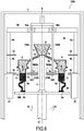
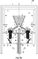
- FIGS 7A and 7B an installation variant 1100 which comprises, in addition to the second movable heat shield 210, a fourth heat shield 310 relative to the molds 6.
- the fourth heat shield 310 is located on the inner side C2 of each of the molds 6.
- the fourth heat shield 310 is superimposed on the second heat shield 210 along the axis of the enclosure X.
- the first displacement system comprises a jack 170 configured to lower the movable support 80 and the molds 6 in the furnace in order to solidify the molten material 9.
- the second displacement system comprises, in the illustrated example, a jack 190 at the end 190a of which the second heat shield 210 is present.
- the jack 190 is configured to slide inside the jack 170.
- the cylinders 170 and 190 extend along the same axis, corresponding in the example shown to the axis X.
- the installation 1100 further comprises a third system. displacement member which comprises a jack 290 at the end 290a of which the fourth heat shield 310 is present.
- the second cylinder 290 is configured to slide inside the first cylinder 190.
- the cylinders 190 and 290 extend along the same axis, corresponding in the example shown to the axis X.
- the width L2 of the fourth heat shield 310 is less than the width L1 of the second heat shield 210.
- the spacing e between the molds 6 at the points 6b is less than the width L1.
- the second heat shield 210 can not rise to a position higher than that of the points 6b of the molds 6.
- the second heat shield 210 will follow the solidification front during a first phase of directed solidification and will be positioned opposite this front during this first phase. Once the second heat shield can no longer continue to follow the solidification front due to insufficient spacing e between the molds 6, the displacement of the second heat shield 210 will be stopped.
- the displacement of the fourth heat shield 310 will then be initiated using the third displacement system so that the fourth heat shield 310, narrower than the second heat shield, continues to follow the solidification front so as to be positioned next to this last (see Figure 7B and nonzero spacing d between the two heat shields 210 and 310).
- the second heat shield 210 can be held fixed during the movement of the fourth heat shield 310.
- the fourth heat shield 310 has indeed a width L2 less than the spacing e and can therefore continue to follow the solidification front beyond the points 6b (see Figure 7B ).
Landscapes
- Chemical & Material Sciences (AREA)
- Engineering & Computer Science (AREA)
- Crystallography & Structural Chemistry (AREA)
- Materials Engineering (AREA)
- Metallurgy (AREA)
- Organic Chemistry (AREA)
- Mechanical Engineering (AREA)
- Inorganic Chemistry (AREA)
- Powder Metallurgy (AREA)
- Crystals, And After-Treatments Of Crystals (AREA)
- Turbine Rotor Nozzle Sealing (AREA)
Applications Claiming Priority (1)
| Application Number | Priority Date | Filing Date | Title |
|---|---|---|---|
| FR1750167A FR3061722B1 (fr) | 2017-01-09 | 2017-01-09 | Installation pour la fabrication d'une piece par mise en oeuvre d'un procede bridgman |
Publications (2)
| Publication Number | Publication Date |
|---|---|
| EP3346030A1 true EP3346030A1 (de) | 2018-07-11 |
| EP3346030B1 EP3346030B1 (de) | 2019-03-06 |
Family
ID=59031046
Family Applications (1)
| Application Number | Title | Priority Date | Filing Date |
|---|---|---|---|
| EP18150263.4A Active EP3346030B1 (de) | 2017-01-09 | 2018-01-04 | Anlage für die herstellung eines teils durch umsetzung eines bridgman-verfahrens |
Country Status (4)
| Country | Link |
|---|---|
| US (1) | US10562096B2 (de) |
| EP (1) | EP3346030B1 (de) |
| CN (1) | CN108286068B (de) |
| FR (1) | FR3061722B1 (de) |
Families Citing this family (6)
| Publication number | Priority date | Publication date | Assignee | Title |
|---|---|---|---|---|
| CN109351951B (zh) * | 2018-11-29 | 2020-12-22 | 中国科学院金属研究所 | 一种减少单晶叶片平台疏松缺陷的工艺方法 |
| CN111331077A (zh) * | 2020-04-27 | 2020-06-26 | 泰州市金鹰精密铸造有限公司 | 基于高硅轻质化过共晶铝硅合金产品铸造的尺寸控制方法 |
| CN113046821A (zh) * | 2021-05-11 | 2021-06-29 | 宁国市华成金研科技有限公司 | 一种多工位定向凝固及单晶铸造炉 |
| US11833581B1 (en) * | 2022-09-07 | 2023-12-05 | General Electric Company | Heat extraction or retention during directional solidification of a casting component |
| CN115889734A (zh) * | 2022-10-27 | 2023-04-04 | 中国航发北京航空材料研究院 | 一种可实时监控温度梯度的加热器底座装置 |
| CN116079034A (zh) * | 2023-02-07 | 2023-05-09 | 嵊州市浙江工业大学创新研究院 | 适用于定向凝固铸造炉的单晶叶片温度梯度分布优化装置 |
Citations (3)
| Publication number | Priority date | Publication date | Assignee | Title |
|---|---|---|---|---|
| EP0278762A2 (de) * | 1987-02-11 | 1988-08-17 | PCC Airfoils, Inc. | Einrichtung und Verfahren zur Anwendung beim Giessen von Gegenständen |
| JP2002144019A (ja) * | 2000-11-02 | 2002-05-21 | Mitsubishi Heavy Ind Ltd | 一方向凝固鋳造方法及びその装置 |
| GB2404353A (en) * | 2003-07-30 | 2005-02-02 | Howmet Res Corp | Spring biassed thermal baffle in directional solidification casting apparatus |
Family Cites Families (5)
| Publication number | Priority date | Publication date | Assignee | Title |
|---|---|---|---|---|
| US3714977A (en) * | 1971-07-23 | 1973-02-06 | United Aircraft Corp | Method and apparatus for the production of directionally solidified castings |
| JP2003191067A (ja) * | 2001-12-21 | 2003-07-08 | Mitsubishi Heavy Ind Ltd | 方向性凝固鋳造装置、方向性凝固鋳造方法 |
| CN1179808C (zh) * | 2002-05-16 | 2004-12-15 | 上海交通大学 | 锆基大块非晶合金分步冷却连续铸造方法 |
| US10082032B2 (en) * | 2012-11-06 | 2018-09-25 | Howmet Corporation | Casting method, apparatus, and product |
| CN104690256B (zh) * | 2015-02-11 | 2017-03-01 | 西北工业大学 | 控制镍基高温合金台阶状铸件杂晶缺陷的定向凝固方法 |
-
2017
- 2017-01-09 FR FR1750167A patent/FR3061722B1/fr active Active
-
2018
- 2018-01-04 EP EP18150263.4A patent/EP3346030B1/de active Active
- 2018-01-08 US US15/864,546 patent/US10562096B2/en active Active
- 2018-01-09 CN CN201810018895.XA patent/CN108286068B/zh active Active
Patent Citations (3)
| Publication number | Priority date | Publication date | Assignee | Title |
|---|---|---|---|---|
| EP0278762A2 (de) * | 1987-02-11 | 1988-08-17 | PCC Airfoils, Inc. | Einrichtung und Verfahren zur Anwendung beim Giessen von Gegenständen |
| JP2002144019A (ja) * | 2000-11-02 | 2002-05-21 | Mitsubishi Heavy Ind Ltd | 一方向凝固鋳造方法及びその装置 |
| GB2404353A (en) * | 2003-07-30 | 2005-02-02 | Howmet Res Corp | Spring biassed thermal baffle in directional solidification casting apparatus |
Also Published As
| Publication number | Publication date |
|---|---|
| US10562096B2 (en) | 2020-02-18 |
| FR3061722A1 (fr) | 2018-07-13 |
| CN108286068A (zh) | 2018-07-17 |
| FR3061722B1 (fr) | 2019-07-26 |
| CN108286068B (zh) | 2021-02-26 |
| EP3346030B1 (de) | 2019-03-06 |
| US20180193906A1 (en) | 2018-07-12 |
Similar Documents
| Publication | Publication Date | Title |
|---|---|---|
| EP3346030B1 (de) | Anlage für die herstellung eines teils durch umsetzung eines bridgman-verfahrens | |
| EP2670547B2 (de) | Sinter- und laserfusionsvorrichtung mit einer vorrichtung zum erwärmen von pulver durch induktion | |
| EP2751304B1 (de) | Herstellung einer komponente aus einkristallinem oder gerichtet erstarrtem material | |
| FR2858257A1 (fr) | Procede et dispositif de solidification dirigee | |
| EP2014803B1 (de) | Vorrichtung zur Herstellung eines Blocks aus kristallinem Material mit Modulation der Wärmeleitfähigkeit | |
| FR2991613A1 (fr) | Procede de fabrication de piece par fusion selective ou frittage selectif de lits de poudre(s) au moyen d'un faisceau de haute energie | |
| JP2018537594A (ja) | 付加製造するための方法、付加製造によって製造されたコンポーネント、及び付加製造のための装置 | |
| WO2011121251A1 (fr) | Procédé et dispositif pour la fabrication d'une virole bi-matériaux, et virole ainsi réalisée. | |
| WO2018162829A1 (fr) | Procede d'infiltration d'une preforme poreuse | |
| CA2954024A1 (fr) | Procede de fabrication d'une aube bi-composant pour moteur a turbine a gaz et aube obtenue par un tel procede | |
| EP0743114B1 (de) | Verfahren zur Schmierung der Wände einer Stranggusskokille für Metalle und Kokille zur Durchführung dieses Verfahrens | |
| US20190061266A1 (en) | Apparatus for a facility and method of additively manufacturing a component | |
| FR3026414A1 (fr) | Creuset pour la cristallisation de silicium multi-cristallin ou quasi-monocristallin par reprise sur germe | |
| EP3475012B1 (de) | Kühlofen mit gerichteter erstarrung und kühlverfahren mit solch einem ofen | |
| JP6401051B2 (ja) | 多結晶シリコンインゴットの製造方法 | |
| US12157166B2 (en) | Method for holding a part blank by fluid expansion in an additively manufactured holding portion | |
| EP0993890B1 (de) | Rohrförmige Stranggusskokille für Metalle | |
| FR3105038A1 (fr) | Module de fabrication additive amovible | |
| FR3095974A1 (fr) | Dispositif et procede de fabrication additive par fusion laser sur lit de poudre | |
| EP0136197A1 (de) | Verfahren und Vorrichtung zur Herstellung eines Gegenstandes durch Giessen in einem flüssigen Milieu | |
| EP3472121A1 (de) | Verfahren zur herstellung einer turbomaschinenkomponente | |
| FR3053266A1 (fr) | Machine et procede pour le decochage de grappes de fonderie |
Legal Events
| Date | Code | Title | Description |
|---|---|---|---|
| PUAI | Public reference made under article 153(3) epc to a published international application that has entered the european phase |
Free format text: ORIGINAL CODE: 0009012 |
|
| STAA | Information on the status of an ep patent application or granted ep patent |
Free format text: STATUS: REQUEST FOR EXAMINATION WAS MADE |
|
| 17P | Request for examination filed |
Effective date: 20180104 |
|
| AK | Designated contracting states |
Kind code of ref document: A1 Designated state(s): AL AT BE BG CH CY CZ DE DK EE ES FI FR GB GR HR HU IE IS IT LI LT LU LV MC MK MT NL NO PL PT RO RS SE SI SK SM TR |
|
| AX | Request for extension of the european patent |
Extension state: BA ME |
|
| RIC1 | Information provided on ipc code assigned before grant |
Ipc: C30B 11/00 20060101AFI20180830BHEP Ipc: B22D 27/04 20060101ALI20180830BHEP Ipc: C30B 29/52 20060101ALI20180830BHEP |
|
| GRAP | Despatch of communication of intention to grant a patent |
Free format text: ORIGINAL CODE: EPIDOSNIGR1 |
|
| STAA | Information on the status of an ep patent application or granted ep patent |
Free format text: STATUS: GRANT OF PATENT IS INTENDED |
|
| INTG | Intention to grant announced |
Effective date: 20181008 |
|
| GRAS | Grant fee paid |
Free format text: ORIGINAL CODE: EPIDOSNIGR3 |
|
| GRAA | (expected) grant |
Free format text: ORIGINAL CODE: 0009210 |
|
| STAA | Information on the status of an ep patent application or granted ep patent |
Free format text: STATUS: THE PATENT HAS BEEN GRANTED |
|
| AK | Designated contracting states |
Kind code of ref document: B1 Designated state(s): AL AT BE BG CH CY CZ DE DK EE ES FI FR GB GR HR HU IE IS IT LI LT LU LV MC MK MT NL NO PL PT RO RS SE SI SK SM TR |
|
| REG | Reference to a national code |
Ref country code: GB Ref legal event code: FG4D Free format text: NOT ENGLISH |
|
| REG | Reference to a national code |
Ref country code: CH Ref legal event code: EP Ref country code: AT Ref legal event code: REF Ref document number: 1104684 Country of ref document: AT Kind code of ref document: T Effective date: 20190315 |
|
| REG | Reference to a national code |
Ref country code: DE Ref legal event code: R096 Ref document number: 602018000011 Country of ref document: DE |
|
| REG | Reference to a national code |
Ref country code: IE Ref legal event code: FG4D Free format text: LANGUAGE OF EP DOCUMENT: FRENCH |
|
| REG | Reference to a national code |
Ref country code: SE Ref legal event code: TRGR |
|
| REG | Reference to a national code |
Ref country code: NL Ref legal event code: MP Effective date: 20190306 |
|
| REG | Reference to a national code |
Ref country code: LT Ref legal event code: MG4D |
|
| PG25 | Lapsed in a contracting state [announced via postgrant information from national office to epo] |
Ref country code: NO Free format text: LAPSE BECAUSE OF FAILURE TO SUBMIT A TRANSLATION OF THE DESCRIPTION OR TO PAY THE FEE WITHIN THE PRESCRIBED TIME-LIMIT Effective date: 20190606 Ref country code: LT Free format text: LAPSE BECAUSE OF FAILURE TO SUBMIT A TRANSLATION OF THE DESCRIPTION OR TO PAY THE FEE WITHIN THE PRESCRIBED TIME-LIMIT Effective date: 20190306 Ref country code: FI Free format text: LAPSE BECAUSE OF FAILURE TO SUBMIT A TRANSLATION OF THE DESCRIPTION OR TO PAY THE FEE WITHIN THE PRESCRIBED TIME-LIMIT Effective date: 20190306 |
|
| PG25 | Lapsed in a contracting state [announced via postgrant information from national office to epo] |
Ref country code: HR Free format text: LAPSE BECAUSE OF FAILURE TO SUBMIT A TRANSLATION OF THE DESCRIPTION OR TO PAY THE FEE WITHIN THE PRESCRIBED TIME-LIMIT Effective date: 20190306 Ref country code: RS Free format text: LAPSE BECAUSE OF FAILURE TO SUBMIT A TRANSLATION OF THE DESCRIPTION OR TO PAY THE FEE WITHIN THE PRESCRIBED TIME-LIMIT Effective date: 20190306 Ref country code: LV Free format text: LAPSE BECAUSE OF FAILURE TO SUBMIT A TRANSLATION OF THE DESCRIPTION OR TO PAY THE FEE WITHIN THE PRESCRIBED TIME-LIMIT Effective date: 20190306 Ref country code: BG Free format text: LAPSE BECAUSE OF FAILURE TO SUBMIT A TRANSLATION OF THE DESCRIPTION OR TO PAY THE FEE WITHIN THE PRESCRIBED TIME-LIMIT Effective date: 20190606 Ref country code: NL Free format text: LAPSE BECAUSE OF FAILURE TO SUBMIT A TRANSLATION OF THE DESCRIPTION OR TO PAY THE FEE WITHIN THE PRESCRIBED TIME-LIMIT Effective date: 20190306 Ref country code: GR Free format text: LAPSE BECAUSE OF FAILURE TO SUBMIT A TRANSLATION OF THE DESCRIPTION OR TO PAY THE FEE WITHIN THE PRESCRIBED TIME-LIMIT Effective date: 20190607 |
|
| REG | Reference to a national code |
Ref country code: AT Ref legal event code: MK05 Ref document number: 1104684 Country of ref document: AT Kind code of ref document: T Effective date: 20190306 |
|
| PG25 | Lapsed in a contracting state [announced via postgrant information from national office to epo] |
Ref country code: RO Free format text: LAPSE BECAUSE OF FAILURE TO SUBMIT A TRANSLATION OF THE DESCRIPTION OR TO PAY THE FEE WITHIN THE PRESCRIBED TIME-LIMIT Effective date: 20190306 Ref country code: EE Free format text: LAPSE BECAUSE OF FAILURE TO SUBMIT A TRANSLATION OF THE DESCRIPTION OR TO PAY THE FEE WITHIN THE PRESCRIBED TIME-LIMIT Effective date: 20190306 Ref country code: ES Free format text: LAPSE BECAUSE OF FAILURE TO SUBMIT A TRANSLATION OF THE DESCRIPTION OR TO PAY THE FEE WITHIN THE PRESCRIBED TIME-LIMIT Effective date: 20190306 Ref country code: PT Free format text: LAPSE BECAUSE OF FAILURE TO SUBMIT A TRANSLATION OF THE DESCRIPTION OR TO PAY THE FEE WITHIN THE PRESCRIBED TIME-LIMIT Effective date: 20190706 Ref country code: AL Free format text: LAPSE BECAUSE OF FAILURE TO SUBMIT A TRANSLATION OF THE DESCRIPTION OR TO PAY THE FEE WITHIN THE PRESCRIBED TIME-LIMIT Effective date: 20190306 Ref country code: CZ Free format text: LAPSE BECAUSE OF FAILURE TO SUBMIT A TRANSLATION OF THE DESCRIPTION OR TO PAY THE FEE WITHIN THE PRESCRIBED TIME-LIMIT Effective date: 20190306 Ref country code: SK Free format text: LAPSE BECAUSE OF FAILURE TO SUBMIT A TRANSLATION OF THE DESCRIPTION OR TO PAY THE FEE WITHIN THE PRESCRIBED TIME-LIMIT Effective date: 20190306 |
|
| PG25 | Lapsed in a contracting state [announced via postgrant information from national office to epo] |
Ref country code: PL Free format text: LAPSE BECAUSE OF FAILURE TO SUBMIT A TRANSLATION OF THE DESCRIPTION OR TO PAY THE FEE WITHIN THE PRESCRIBED TIME-LIMIT Effective date: 20190306 Ref country code: SM Free format text: LAPSE BECAUSE OF FAILURE TO SUBMIT A TRANSLATION OF THE DESCRIPTION OR TO PAY THE FEE WITHIN THE PRESCRIBED TIME-LIMIT Effective date: 20190306 |
|
| REG | Reference to a national code |
Ref country code: DE Ref legal event code: R097 Ref document number: 602018000011 Country of ref document: DE |
|
| PG25 | Lapsed in a contracting state [announced via postgrant information from national office to epo] |
Ref country code: AT Free format text: LAPSE BECAUSE OF FAILURE TO SUBMIT A TRANSLATION OF THE DESCRIPTION OR TO PAY THE FEE WITHIN THE PRESCRIBED TIME-LIMIT Effective date: 20190306 Ref country code: IS Free format text: LAPSE BECAUSE OF FAILURE TO SUBMIT A TRANSLATION OF THE DESCRIPTION OR TO PAY THE FEE WITHIN THE PRESCRIBED TIME-LIMIT Effective date: 20190706 |
|
| PLBE | No opposition filed within time limit |
Free format text: ORIGINAL CODE: 0009261 |
|
| STAA | Information on the status of an ep patent application or granted ep patent |
Free format text: STATUS: NO OPPOSITION FILED WITHIN TIME LIMIT |
|
| PG25 | Lapsed in a contracting state [announced via postgrant information from national office to epo] |
Ref country code: DK Free format text: LAPSE BECAUSE OF FAILURE TO SUBMIT A TRANSLATION OF THE DESCRIPTION OR TO PAY THE FEE WITHIN THE PRESCRIBED TIME-LIMIT Effective date: 20190306 |
|
| 26N | No opposition filed |
Effective date: 20191209 |
|
| PG25 | Lapsed in a contracting state [announced via postgrant information from national office to epo] |
Ref country code: TR Free format text: LAPSE BECAUSE OF FAILURE TO SUBMIT A TRANSLATION OF THE DESCRIPTION OR TO PAY THE FEE WITHIN THE PRESCRIBED TIME-LIMIT Effective date: 20190306 |
|
| PG25 | Lapsed in a contracting state [announced via postgrant information from national office to epo] |
Ref country code: MC Free format text: LAPSE BECAUSE OF FAILURE TO SUBMIT A TRANSLATION OF THE DESCRIPTION OR TO PAY THE FEE WITHIN THE PRESCRIBED TIME-LIMIT Effective date: 20190306 |
|
| REG | Reference to a national code |
Ref country code: BE Ref legal event code: MM Effective date: 20200131 |
|
| PG25 | Lapsed in a contracting state [announced via postgrant information from national office to epo] |
Ref country code: LU Free format text: LAPSE BECAUSE OF NON-PAYMENT OF DUE FEES Effective date: 20200104 |
|
| PG25 | Lapsed in a contracting state [announced via postgrant information from national office to epo] |
Ref country code: BE Free format text: LAPSE BECAUSE OF NON-PAYMENT OF DUE FEES Effective date: 20200131 |
|
| PG25 | Lapsed in a contracting state [announced via postgrant information from national office to epo] |
Ref country code: IE Free format text: LAPSE BECAUSE OF NON-PAYMENT OF DUE FEES Effective date: 20200104 |
|
| REG | Reference to a national code |
Ref country code: CH Ref legal event code: PL |
|
| PG25 | Lapsed in a contracting state [announced via postgrant information from national office to epo] |
Ref country code: CH Free format text: LAPSE BECAUSE OF NON-PAYMENT OF DUE FEES Effective date: 20210131 Ref country code: LI Free format text: LAPSE BECAUSE OF NON-PAYMENT OF DUE FEES Effective date: 20210131 |
|
| PG25 | Lapsed in a contracting state [announced via postgrant information from national office to epo] |
Ref country code: MT Free format text: LAPSE BECAUSE OF FAILURE TO SUBMIT A TRANSLATION OF THE DESCRIPTION OR TO PAY THE FEE WITHIN THE PRESCRIBED TIME-LIMIT Effective date: 20190306 Ref country code: CY Free format text: LAPSE BECAUSE OF FAILURE TO SUBMIT A TRANSLATION OF THE DESCRIPTION OR TO PAY THE FEE WITHIN THE PRESCRIBED TIME-LIMIT Effective date: 20190306 |
|
| PG25 | Lapsed in a contracting state [announced via postgrant information from national office to epo] |
Ref country code: MK Free format text: LAPSE BECAUSE OF FAILURE TO SUBMIT A TRANSLATION OF THE DESCRIPTION OR TO PAY THE FEE WITHIN THE PRESCRIBED TIME-LIMIT Effective date: 20190306 |
|
| PG25 | Lapsed in a contracting state [announced via postgrant information from national office to epo] |
Ref country code: SI Free format text: LAPSE BECAUSE OF FAILURE TO SUBMIT A TRANSLATION OF THE DESCRIPTION OR TO PAY THE FEE WITHIN THE PRESCRIBED TIME-LIMIT Effective date: 20190306 |
|
| PGFP | Annual fee paid to national office [announced via postgrant information from national office to epo] |
Ref country code: SE Payment date: 20260121 Year of fee payment: 9 |
|
| PGFP | Annual fee paid to national office [announced via postgrant information from national office to epo] |
Ref country code: GB Payment date: 20260122 Year of fee payment: 9 |
|
| PGFP | Annual fee paid to national office [announced via postgrant information from national office to epo] |
Ref country code: DE Payment date: 20260120 Year of fee payment: 9 |
|
| PGFP | Annual fee paid to national office [announced via postgrant information from national office to epo] |
Ref country code: IT Payment date: 20260130 Year of fee payment: 9 |
|
| PGFP | Annual fee paid to national office [announced via postgrant information from national office to epo] |
Ref country code: FR Payment date: 20260121 Year of fee payment: 9 |