EP3346036B1 - Appareil et procédé de production de feuilles - Google Patents
Appareil et procédé de production de feuilles Download PDFInfo
- Publication number
- EP3346036B1 EP3346036B1 EP16841111.4A EP16841111A EP3346036B1 EP 3346036 B1 EP3346036 B1 EP 3346036B1 EP 16841111 A EP16841111 A EP 16841111A EP 3346036 B1 EP3346036 B1 EP 3346036B1
- Authority
- EP
- European Patent Office
- Prior art keywords
- unit
- air flow
- air
- sheet manufacturing
- manufacturing apparatus
- Prior art date
- Legal status (The legal status is an assumption and is not a legal conclusion. Google has not performed a legal analysis and makes no representation as to the accuracy of the status listed.)
- Active
Links
Images


Classifications
-
- D—TEXTILES; PAPER
- D04—BRAIDING; LACE-MAKING; KNITTING; TRIMMINGS; NON-WOVEN FABRICS
- D04H—MAKING TEXTILE FABRICS, e.g. FROM FIBRES OR FILAMENTARY MATERIAL; FABRICS MADE BY SUCH PROCESSES OR APPARATUS, e.g. FELTS, NON-WOVEN FABRICS; COTTON-WOOL; WADDING ; NON-WOVEN FABRICS FROM STAPLE FIBRES, FILAMENTS OR YARNS, BONDED WITH AT LEAST ONE WEB-LIKE MATERIAL DURING THEIR CONSOLIDATION
- D04H1/00—Non-woven fabrics formed wholly or mainly of staple fibres or like relatively short fibres
- D04H1/70—Non-woven fabrics formed wholly or mainly of staple fibres or like relatively short fibres characterised by the method of forming fleeces or layers, e.g. reorientation of fibres
- D04H1/72—Non-woven fabrics formed wholly or mainly of staple fibres or like relatively short fibres characterised by the method of forming fleeces or layers, e.g. reorientation of fibres the fibres being randomly arranged
- D04H1/732—Non-woven fabrics formed wholly or mainly of staple fibres or like relatively short fibres characterised by the method of forming fleeces or layers, e.g. reorientation of fibres the fibres being randomly arranged by fluid current, e.g. air-lay
-
- B—PERFORMING OPERATIONS; TRANSPORTING
- B27—WORKING OR PRESERVING WOOD OR SIMILAR MATERIAL; NAILING OR STAPLING MACHINES IN GENERAL
- B27N—MANUFACTURE BY DRY PROCESSES OF ARTICLES, WITH OR WITHOUT ORGANIC BINDING AGENTS, MADE FROM PARTICLES OR FIBRES CONSISTING OF WOOD OR OTHER LIGNOCELLULOSIC OR LIKE ORGANIC MATERIAL
- B27N3/00—Manufacture of substantially flat articles, e.g. boards, from particles or fibres
- B27N3/04—Manufacture of substantially flat articles, e.g. boards, from particles or fibres from fibres
-
- B—PERFORMING OPERATIONS; TRANSPORTING
- B27—WORKING OR PRESERVING WOOD OR SIMILAR MATERIAL; NAILING OR STAPLING MACHINES IN GENERAL
- B27N—MANUFACTURE BY DRY PROCESSES OF ARTICLES, WITH OR WITHOUT ORGANIC BINDING AGENTS, MADE FROM PARTICLES OR FIBRES CONSISTING OF WOOD OR OTHER LIGNOCELLULOSIC OR LIKE ORGANIC MATERIAL
- B27N3/00—Manufacture of substantially flat articles, e.g. boards, from particles or fibres
- B27N3/08—Moulding or pressing
- B27N3/10—Moulding of mats
- B27N3/12—Moulding of mats from fibres
-
- B—PERFORMING OPERATIONS; TRANSPORTING
- B27—WORKING OR PRESERVING WOOD OR SIMILAR MATERIAL; NAILING OR STAPLING MACHINES IN GENERAL
- B27N—MANUFACTURE BY DRY PROCESSES OF ARTICLES, WITH OR WITHOUT ORGANIC BINDING AGENTS, MADE FROM PARTICLES OR FIBRES CONSISTING OF WOOD OR OTHER LIGNOCELLULOSIC OR LIKE ORGANIC MATERIAL
- B27N3/00—Manufacture of substantially flat articles, e.g. boards, from particles or fibres
- B27N3/08—Moulding or pressing
- B27N3/18—Auxiliary operations, e.g. preheating, humidifying, cutting-off
-
- B—PERFORMING OPERATIONS; TRANSPORTING
- B27—WORKING OR PRESERVING WOOD OR SIMILAR MATERIAL; NAILING OR STAPLING MACHINES IN GENERAL
- B27N—MANUFACTURE BY DRY PROCESSES OF ARTICLES, WITH OR WITHOUT ORGANIC BINDING AGENTS, MADE FROM PARTICLES OR FIBRES CONSISTING OF WOOD OR OTHER LIGNOCELLULOSIC OR LIKE ORGANIC MATERIAL
- B27N3/00—Manufacture of substantially flat articles, e.g. boards, from particles or fibres
- B27N3/007—Manufacture of substantially flat articles, e.g. boards, from particles or fibres and at least partly composed of recycled material
Definitions
- the present invention relates to a sheet manufacturing apparatus, and a sheet manufacturing method.
- Sheet manufacturing apparatuses conventionally use a slurry process in which feedstock including fiber is soaked in water, defibrated by primarily a mechanical action, and then rescreened. Sheet manufacturing apparatuses using such wet slurry methods require a large amount of water, and are large. Maintenance of the water processing system is also laborious, and the drying process requires much energy.
- PTL 1 describes defibrating pieces of paper into fibers in a dry-process defibrator, deinking the fibers in a cyclone separator, passing the deinked fiber through a foraminous screen on the surface of a forming drum, and laying the fiber on a mesh belt using the suction of a suction device to form paper.
- the technology described in PTL 1 strengthens the hydrogen bonds between fibers by misting the sheet of deinked fiber laid on the mesh belt with water by means of a water sprayer.
- An objective of the several embodiments of the present invention is to provide a sheet manufacturing apparatus sheet that can suppress adhesion of the deposited material to the rollers.
- Another objective of the several embodiments of the present invention is to provide a sheet manufacturing method sheet that can suppress adhesion of the deposited material to the rollers.
- DE 196 35 410 relates to the production of biodegradable insulation board materials.
- the start material is reduced to chips and/or fibres, treated with a glue, and dried before or after the glue application, to form an intermediate material to be scattered and spread to form a felting.
- the felting is passed through successive processing stages. Initially, it is compressed to the required board thickness, which is maintained through the system. Then the compressed material is held for 10-20 secs. in an environment of a steam/air mixture, without premature setting of the bonding agent. In the third stage, the material is subjected to a hot air flow to dry and set it. Also claimed is an assembly with a perforated conveyor belt which travels continuously through a combined calibration/bonding/drying station, where the material is held between two belts.
- the material entry between the belts has a wedge shape to give a steady compression into the required material thickness.
- the belt entry zone leads to a heating zone, where a mixture of steam and air is fed in to give a pressure or suction drying action with a hot air steam passing through the material.
- US 2 925 360 relates to the manufacture of felted mats from individualised ultimate wood fibers.
- the present invention is directed to solving at least part of the foregoing problem, and can be embodied as described in the following claims and examples.
- a sheet manufacturing apparatus thus comprised can humidify deposited material to the inside by the air flow produced by the first air flow generator, and can suppression water droplets and moisture adhering to only the surface of the deposited material.
- a sheet manufacturing apparatus thus comprised can therefore moisten the deposited material uniformly through the thickness thereof, and, compared with simply misting water droplets to deposit water droplets or moisture on only the surface of the deposited material, can reduce the amount of water droplets and moisture on the surface of the deposited material. As a result, deposited material wrapping onto rollers can be suppressed in this sheet manufacturing apparatus.
- the air-laying unit has a first housing that defines a deposition area for depositing the material; and the humidifying unit has a second housing that defines a humidifying area for humidifying the deposited material.
- a sheet manufacturing apparatus thus comprised can suppress excessive humidifying the inside of the second housing by the humidifying unit, and can suppress a drop in the quality of the manufactured sheet.
- the first air flow generator is a first suction device disposed on the back side, which faces the opposite side as the support surface; and the air-laying unit has a second suction device disposed on the back side and configured to produce air flow causing the material to accumulate on the support surface.
- the sheet manufacturing apparatus thus comprised can separately set the volume and velocity of the air flow produced by the first suction device, and the volume and velocity of the air flow produced by the second suction device.
- the air-laying unit has a second air flow generator that produces air flow causing the material to accumulate on the support surface; and the first air flow generator and second air flow generator are a common suction device disposed on the back side, which faces the opposite side as the support surface.
- This configuration enables reducing the size of the sheet manufacturing apparatus.
- the sheet manufacturing apparatus thus comprised can suppress wrapping of the deposited material onto the second roller.
- the air-laying unit has a second air flow generator configured to produce air flow causing the material to accumulate on the support surface; and the velocity of the air flow produced at the support surface by the first air flow generator is less than the velocity of the air flow produced at the support surface by the second air flow generator.
- the sheet manufacturing apparatus in this configuration can improve the quality of the manufactured sheet while suppressing separation of the fiber and resin.
- a sheet manufacturing apparatus has a first suction device configured to suction the droplets or humidified air produced by the generator from the back side, which faces the opposite direction as the support surface.
- a sheet manufacturing apparatus thus comprised can efficiently humidify to the inside the deposited material formed on the support surface, and can thereby suppress the deposited material from wrapping onto the roller.
- the air-laying unit has a foraminous drum unit; and a second suction device configured to suction, from the back side, material that passes through openings in the drum unit.
- the sheet manufacturing apparatus thus configured can suppress deposited material from wrapping onto the roller.
- the sheet manufacturing method thus comprised can suppress deposited material from wrapping onto the roller.
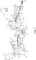
- FIG. 1 schematically illustrates a sheet manufacturing apparatus 100 according to this first embodiment.
- the sheet manufacturing apparatus 100 has a supply unit 10, manufacturing unit 102, and control unit 104.
- the manufacturing unit 102 manufactures sheets.
- the manufacturing unit 102 includes a shredder 12, defibrating unit 20, separator 40, first web forming unit 45, rotor 49, mixing unit 50, air-laying unit 60, second web forming unit 70, sheet forming unit 80, and cutting unit 90.
- the supply unit 10 supples feedstock to the shredder 12.
- the supply unit 10 is, for example, an automatic loader for continuously supplying feedstock material to the shredder 12.
- the feedstock supplied by the supply unit 10 includes fiber from recovered paper or pulp sheets, for example.
- the shredder 12 cuts feedstock supplied by the supply unit 10 into shreds in air.
- the shreds in this example are pieces a few centimeters in size.
- the shredder 12 has shredder blades 14, and shreds the supplied feedstock by the shredder blades 14.
- a paper shredder is used as the shredder 12.
- the feedstock shredded by the shredder 12 is received into a hopper 1 and carried (conveyed) to the defibrating unit 20 through a conduit 2.
- the defibrating unit 20 defibrates the feedstock shredded by the shredder 12.
- Defibrate as used here is a process of separating feedstock (material to be defibrated) comprising interlocked fibers into individual detangled fibers.
- the defibrating unit 20 also functions to separate particulate such as resin, ink, toner, and sizing agents in the feedstock from the fibers.
- defibrated material Material that has past through the defibrating unit 20 is referred to as defibrated material.
- the defibrated material may also contain resin particles (resin used to bind multiple fibers together), coloring agents such as ink and toner, sizing agents, paper strengthening agents, and other additives that are separated from the fibers when the fibers are detangled.
- the shape of the detangled defibrated material is a string or ribbon.
- the detangled, defibrated material may be separated from (not interlocked with) other detangled fibers, or may be in lumps interlocked with other detangled defibrated material (in so-called fiber clumps).
- the defibrating unit 20 defibrates in a dry process in ambient air (air). More specifically, an impeller mill is used as the defibrating unit 20.
- the defibrating unit 20 can also create an air flow that sucks in the feedstock and then discharges the defibrated material.
- the defibrating unit 20 can suction the feedstock with the air flow from the inlet 22, defibrate, and then convey the defibrated material to the exit 24 using the air flow produced by the defibrating unit 20.
- the defibrated material that past the defibrating unit 20 is conveyed through a conduit 3 to the separator 40.
- the air stream conveying the defibrated material from the defibrating unit 20 to the separator 40 may be the air current created by the defibrating unit 20, or a separate blower or other fan unit may be used to create the air current.
- the separator 40 selects fibers by length from the defibrated material defibrated by the defibrating unit 20 that was introduced from the inlet 42.
- the separator 40 has a drum 41.
- a screen (sieve) is used as the drum 41.
- the drum 41 has mesh (filter, screen), and can separate fiber or particles that are smaller than the size of the openings in the mesh (that pass through the mesh, first selected material) from fiber, undefibrated shreds, and clumps that are larger than the openings in the mesh (that do not pass through the mesh, second selected material).
- the first selected material is conveyed through a conduit 7 to the mixing unit 50.
- the second selected material is returned from the exit 44 through another conduit 8 to the defibrating unit 20.
- the drum 41 is a cylindrical sieve that can be rotated by a motor.
- the mesh of the drum 41 may be a metal screen, expanded metal made by expanding a metal sheet with slits formed therein, or punched metal having holes formed by a press in a metal sheet.
- the first web forming unit 45 conveys the first selected material from the separator 40 to the mixing unit 50.
- the first web forming unit 45 includes, for example, a mesh belt 46, tension rollers 47, and a suction unit (suction mechanism) 48.
- the suction unit 48 suctions the first selected material that past through the openings (mesh openings) in the drum 41 and was dispersed in air onto the mesh belt 46.
- the first selected material accumulates on the moving mesh belt 46, forming a web V.
- the basic configuration of the mesh belt 46, tension rollers 47, and suction unit 48 are the same as the mesh belt 72, tension rollers 74, and suction mechanism 76 of the second web forming unit 70 described below.
- the web V is a soft, fluffy web containing a lot of air as a result of passing through the separator 40 and first web forming unit 45.
- the web V formed on the mesh belt 46 is fed into a conduit 7 and conveyed to the mixing unit 50.
- the rotor 49 cuts the web V before the web V is conveyed to the mixing unit 50.
- the rotor 49 has a base 49a, and blades 49b protruding from the base 49a.
- the blades 49b in this example have a flat shape.
- the base 49a turning in direction R, the blades 49b rotate on the axis of the base 49a.
- the rotor 49 is disposed near the first web forming unit 45.
- the rotor 49 is disposed near a tension roller 47a (beside the tension roller 47a) located at the downstream side of the conveyance path of the web V.
- the rotor 49 is disposed at a position where the blades 49b can contact the web V but do not touch the mesh belt 46 on which the web V is laid. As a result, wear (damage) to the mesh belt 46 by the blades 49b can be suppressed.
- the minimum distance between the blades 49b and mesh belt 46 is preferably greater than or equal to 0.05 mm and less than or equal to 0.5 mm. for example.
- the mixing unit 50 mixes an additive containing resin with the first selected material (the first selected material conveyed by the first web forming unit 45) that past the separator 40.
- the mixing unit 50 has an additive supply unit 52 that supplies additive, a conduit 54 for conveying the selected material and additive, and a blower 56.
- the additive is supplied from the additive supply unit 52 through a hopper 9 to a conduit 54.
- Conduit 54 communicates with conduit 7.
- the mixing unit 50 uses the blower 56 to produce an air flow, and can convey while mixing the selected material and additives in the conduit 54.
- the mechanism for mixing the first selected material and additive is not specifically limited, and may mix by means of blades turning at high speed, or may use rotation of the container like a V blender.
- a screw feeder such as shown in FIG. 1 , or a disc feeder not shown, for example, may be used as the additive supply unit 52.
- the additive supplied from the additive supply unit 52 contains resin for binding multiple fibers together. The multiple fibers are not bound when the resin is supplied. The resin melts and binds multiple fibers when passing the sheet forming unit 80.
- the resin supplied from the additive supply unit 52 is a thermoplastic resin or thermoset resin, such as AS resin, ABS resin, polypropylene, polyethylene, polyvinyl chloride, polystyrene, acrylic resin, polyester resin, polyethylene terephthalate, polyethylene ether, polyphenylene ether, polybutylene terephthalate, nylon, polyimide, polycarbonate, polyacetal, polyphenylene sulfide, and polyether ether ketone. These resins may be used individually or in a desirable combination.
- the additive supplied from the additive supply unit 52 may be fibrous or powder.
- the additive supplied from the additive supply unit 52 may also include a coloring agent for coloring the fiber, an anti-blocking suppressant agent to prevent fiber agglomeration, or a flame retardant for making the fiber difficult to burn, in addition to resin for binding fibers.
- the mixture (a mixture of first selected material and additive) that passes the mixing unit 50 is conveyed through a conduit 54 to the air-laying unit 60.
- the mixture that past the mixing unit 50 is introduced from the inlet 62 to the air-laying unit 60, which detangles and disperses the tangled defibrated material (fiber) in air while the mixture precipitates.
- the air-laying unit 60 also detangles interlocked resin fibers. As a result, the air-laying unit 60 can lay the mixture uniformly in the second web forming unit 70.
- the air-laying unit 60 has a drum 61.
- a cylindrical sieve that turns is used as the drum 61.
- the drum 61 has mesh, and causes fiber and particles smaller than the size of the mesh (that pass through the mesh) and contained in the mixture that past the mixing unit 50 to precipitate.
- the configuration of the drum 61 is the same as the configuration of drum 41 in this example.
- the sieve of the drum 61 may be configured without functionality for selecting specific material. More specifically, the "sieve" used as the drum 61 means a device having mesh, and the drum 61 may cause all of the mixture introduced to the drum 61 to precipitate.
- the second web forming unit 70 lays the precipitate that past through the air-laying unit 60 into a web W.
- the web forming unit 70 includes, for example, a mesh belt 72, tension rollers 74, and a suction mechanism 76.
- the mesh belt 72 is moving while precipitate that has past through the holes (mesh) of the drum 61 accumulates thereon.
- the mesh belt 72 is tensioned by the tension rollers 74, and is configured so that air passes through but it is difficult for the precipitate to pass through.
- the mesh belt 72 moves when the tension rollers 74 turn.
- a web W is formed on the mesh belt 72 as a result of the mixture that past the air-laying unit 60 precipitating continuously while the mesh belt 72 moves continuously.
- the mesh belt 72 may be metal, plastic, cloth, or nonwoven cloth.
- the suction mechanism 76 is disposed below the mesh belt 72 (on the opposite side as the air-laying unit 60).
- the suction mechanism 76 produces a downward flow of air (air flow directed from the air-laying unit 60 to the mesh belt 72).
- the mixture distributed in air by the air-laying unit 60 can be pulled onto the mesh belt 72 by the suction mechanism 76.
- the discharge rate from the air-laying unit 60 can be increased.
- a downward air flow can also be created in the descent path of the mixture, and interlocking of defibrated material and additive during descent can be prevented, by the suction mechanism 76.
- a soft, fluffy web W containing much air is formed by material passing through the air-laying unit 60 and second web forming unit 70 (web forming process) as described above.
- the web W laid on the mesh belt 72 is then conveyed to the sheet forming unit 80.
- a moisture content adjustment unit 78 for adjusting the moisture content of the web W is disposed in the example shown in the figure.
- the moisture content adjustment unit 78 adds water or water vapor to the web W to adjust the ratio of water to the web W.
- the sheet forming unit 80 applies heat and pressure to the web W laid on the mesh belt 72, forming a sheet S. By applying heat to the mixture of defibrated material and additive contained in the web W, the sheet forming unit 80 can bind fibers in the mixture together through the additive (resin).
- the sheet forming unit 80 includes a compression unit 82 that compresses the web W, and a heating unit 84 that heats the web W after being compressed by the compression unit 82.
- the compression unit 82 in this example comprises a pair of calender rolls 85 that apply pressure to the web W. Calendering reduces the thickness of the web W and increases the density of the web W.
- a heat roller heating roller
- hot press molding machine hot plate
- hot air blower infrared heater, or flash fuser, for example, may be used as the heating unit 84.
- the heating unit 84 comprises a pair of heat rollers 86.
- a sheet S can be formed while continuously conveying the web W, unlike when the heating unit 84 is configured with a flat press (flat press machine).
- the calender rolls 85 compression unit 82
- the calender rolls 85 can apply greater pressure to the web W than the pressure that can be applied by the heat rollers 86 (heating unit 84). Note that the number of calender rolls 85 and heat rollers 86 is not specifically limited.
- the cutting unit 90 cuts the sheet S formed by the sheet forming unit 80.
- the cutting unit 90 has a first cutter 92 that cuts the sheet S crosswise to the conveyance direction of the sheet S, and a second cutter 94 that cuts the sheet S parallel to the conveyance direction.
- the second cutter 94 cuts the sheet S after passing through the first cutter 92.
- Cut sheets S of a specific size are formed by the process described above.
- the cut sheets S are then discharged to the discharge unit 96.
- FIG. 2 is an enlarged view of FIG. 1 in the area around the air-laying unit 60 and humidifying unit 78.
- the air-laying unit 60 lays material including fiber (defibrated material) and resin (an additive including resin).
- the air-laying unit 60 includes a drum 61 (mesh) in which many holes 61a are formed, a first housing 63, rollers 64a, 64b, and a suction mechanism 76 (second air flow generator).
- the second air flow generator 76 is described in 1.1.1. Configuration above as including a second web forming unit 70, but the second web forming unit 70 may be considered part of the air-laying unit 60. The second air flow generator 76 may also be considered part of the air-laying unit 60, and not the second web forming unit 70.
- the first housing 63 houses the drum 61, for example.
- the first housing 63 is shaped like a box capable of holding the drum 61, and has an opening facing the support surface 71 of the mesh belt 72.
- the first housing 63 defines the deposition area 71a for depositing material including the defibrated material and additive. Material including the defibrated material and additive that past the holes in the drum 61 can be deposited on the support surface 71 within the deposition area 71a in the air-laying unit 60.
- the deposition area 71a is, for example, an area between rollers 64a, 64b, and more specifically is an area defined by the opening in the first housing 63 opposite the support surface 71.
- Rollers 64a, 64b are connected to the first housing 63. More specifically, the rollers 64a, 64b are disposed touching the outside of the first housing 63.
- a sealant in this example, an pile seal
- rollers 64a, 64b may be disposed in contact with the pile seal.
- Roller 64b is located on the downstream side of the roller 64a. Note that downstream side as used here means the side to which the web W flows (the direction in which the web W proceeds toward the discharge unit 96).
- Roller 64b is a roller disposed to the exit of the web W from the first housing 63, and is a roller touching the web W (first roller).
- Rollers 64a, 64b are, for example, metal rollers. More specifically, the material on the surface of the rollers 64a, 64b is aluminum in this example. The rollers 64a, 64b are urged by their own weight or an urging member such as a spring, for example, and touch the mesh belt 72 when the web W has not been deposited. The rollers 64a, 64b suppress material including the defibrated material and additive from leaking from gaps between the first housing 63 and mesh belt 72.
- the second air flow generator 76 is disposed on the opposite side of the support surface 71 (the back side 73) as the mesh belt 72.
- the back side 73 (inside circumference side) is the side facing the opposite direction as the support surface 71 (outside circumference side).
- the second air flow generator 76 is disposed inside the space surrounded by the mesh belt 72.
- the second air flow generator 76 is disposed opposite the first housing 63 with the mesh belt 72 therebetween.
- the second air flow generator 76 produces a current ⁇ for depositing material including the defibrated material and additive on the support surface 71 of the mesh belt 72.
- the current ⁇ is an air flow in a direction intersecting the support surface 71, and is, for example, a current perpendicular to the support surface 71.
- the second air flow generator 76 is a suction device (second suction device) that suctions material passing through the holes 61a in the drum 61 onto the support surface 71 from the back side 73 side.
- the second air flow generator 76 may comprise, for example, a box below the mesh belt 72 with an opening facing the back side 73, and a suction blower that suctions air from inside the box.
- the suction blower creating the current ⁇ may be disposed inside the box, or disposed outside the box and connected to the box by a conduit.
- the humidifying unit 78 humidifies the web W laid by the air-laying unit.
- the humidifying unit 78 includes a generator 170, second housing 172, rollers 173a, 173b, and a first air flow generator 176.
- the generator 170 is disposed on the support surface 71 side. In the example in the figure, the generator 170 is disposed outside the area enclosed by the mesh belt 72.
- the generator 170 produces droplets D or a humidified air flow from the support surface 71 side.
- the generator 170 may produce the droplets D by ultrasonic waves.
- the generator 170 may, for example, apply ultrasonic waves of a frequency of 20 kHz to several MHz to a fluid (water), and produce fine droplets D of several nm to several ⁇ m diameter.
- the generator 170 may also produce steam to produce humidified air. Note that humidified air as used here means air of 70% to 100% relative humidity.
- the second housing 172 is connected through a conduit 171 to the generator 170.
- the second housing 172 is on the support surface 71 side.
- the second housing 172 is, for example, shaped like a box, and has an opening facing the support surface 71 of the mesh belt 72.
- the second housing 172 defines the humidifying area 71b for humidifying the web W.
- the humidifying unit 78 can humidify the web W laid on the support surface 71 inside the humidifying area 71b.
- the humidifying area 71b is, for example, between rollers 173a, 173b, and more specifically is an area defined by the second housing 172 opening facing the support surface 71.
- the humidifying area 71b is downstream from the deposition area 71a.
- Rollers 173a, 173b are connected to the second housing 172. More specifically, the rollers 173a, 173b are disposed contacting the outside of the second housing 172. A seal member (such as a pile seal) is disposed to the outside of the second housing 172, and the rollers 173a, 173b may be disposed in contact with the seal member. Roller 173b is downstream from roller 173a. Roller 173a is also downstream from roller 64b. Roller 173b is a roller disposed to the exit of the web W from the second housing 172, and a roller (second roller) touching the web W after humidifying by the humidifying unit 78.
- a seal member such as a pile seal
- Rollers 173a, 173b are urged by their own weight or an urging member such as a spring, for example, and touch the mesh belt 72 when the web W has not been formed on the mesh belt 72.
- the rollers 173a, 173b suppress leakage of droplets D and humidified air from the gap between the second housing 172 and mesh belt 72.
- the surface free energy of roller 173b is less than the surface free energy of roller 64b.
- the surface free energy of roller 173b is also less than the surface free energy of rollers 64a, 173a.
- the surface of the roller 64b is aluminum or other metal, and the surface of the roller 173b is formed by a fluororesin such as PFA (perfluoroalkoxy alkane) or PTFE (polytetrafluoroethylene) the surface free energy of roller 173b can be made lower than the surface free energy of roller 64b.
- the surface free energy measures surface tension, is the force of tension between (holding together) two materials (solids, liquids, gases, molecules, atoms) in proximity, and is based on the force of a physical bond (intermolecular force, Van del Waals) and not a chemical bond (bonds forming the material itself).
- the surface free energy can be measured using known instruments, for example.
- the first air flow generator 176 is disposed on the back side 73 of the mesh belt 72. In the example in the figure, the first air flow generator 176 is disposed in the area surrounded by the mesh belt 72. The first air flow generator 176 is disposed opposite the second housing 172 with the mesh belt 72 therebetween. The first air flow generator 176 produces a current ⁇ passing through the thickness of the web W. The current ⁇ flows in a direction intersecting the support surface 71, and is, for example, a current perpendicular to the support surface 71.
- the humidifying unit 78 supplies droplets D or humidified air to the web W by means of the current ⁇ produced by the first air flow generator 176.
- the droplets D or humidified air pass through the thickness of the web W by means of the current ⁇ .
- the weight of the droplets D supplied to the web W by the humidifying unit 78 is, for example, greater than or equal to 0.1% and less than or equal to 3% of the weight of the web W per unit volume of the web W.
- the first air flow generator 176 is a suction device (first vacuum device) that suctions droplets D or humidified air produced by the generator 170 from the back side 73.
- the first air flow generator 176 is disposed separately to the second air flow generator 76.
- the first air flow generator 176 may be configured by, for example, a box disposed below the mesh belt 72 with an opening facing the back side 73, and a suction blower that pulls air from inside the box.
- the suction blower that produces the current ⁇ may be disposed inside the box or outside the box and connected to the box by a conduit.
- the speed of the current ⁇ produced by the first air flow generator 176 at the support surface 71 is less than the speed of the current ⁇ produced by the second air flow generator 76 at the support surface 71.
- the speed of the current ⁇ produced by the first air flow generator 176 at the support surface 71 is the average speed of the current ⁇ passing through the support surface 71 at the humidifying area 71b (more specifically, the average speed of the current ⁇ passing through perpendicularly).
- the speed of the current ⁇ produced by the second air flow generator 76 at the support surface 71 is the average speed of the current ⁇ passing through the support surface 71 in the deposition area 71a (more specifically, the average speed of the current ⁇ passing through perpendicularly).
- the speed of the current ⁇ passing through the support surface 71 at the humidifying area 71b is, for example, greater than or equal to 0.05 m/s, 0.2 m/s.
- the speed of the current ⁇ produced by the second air flow generator 76 at the support surface 71 is, for example, 0.2 m/s, 5.0 m/s.
- the speed of currents ⁇ and ⁇ can be measured by an anemometer known from the literature.
- the control unit 104 may also control the air flow generators 76, 176 to adjust the speed of currents ⁇ and ⁇ . Note that the speed of the air current may also be referred to as the air speed.
- the humidifying unit 78 includes the first air flow generator 176, which produces current ⁇ , which is an air flow intersecting the support surface 71 that supports the deposited material (web W) and passes through the web W, and supplies droplets D or humidified air to the web W by means of the current ⁇ produced by the first air flow generator 176.
- the sheet manufacturing apparatus 100 can humidify the web W to the inside by means of the current ⁇ , and can suppress the adhesion of droplets or moisture to just the surface of the web W.
- the sheet manufacturing apparatus 100 can humidify the web W uniformly through the thickness thereof, and can reduce the amount of droplets or moisture on the surface of the web W compared with simply spraying water droplets and humidifying the surface of the web W with water droplets or moisture. As a result, the sheet manufacturing apparatus 100 can suppress the web W from wrapping around roller 173b. Furthermore, because the web W humidified by droplets D or humidified air is can be compressed to high density when calendered in the compression unit 82 in the sheet manufacturing apparatus 100, bond strength between the defibrated fibers or between the defibrated material and additive can be increased.
- the sheet manufacturing apparatus 100 can also increase, by means of the current ⁇ , the amount of moisture (for example, the amount of droplets in the web W) per unit time in the web W near the back side 73 in particular.
- the web W can be efficiently humidified to the inside.
- the air-laying unit 60 includes a first housing 63 that defines the deposition area 71a for depositing material including defibrated material and additive; and the humidifying unit 78 includes a second housing 172 defining the humidifying area 71b for humidifying the web W.
- the sheet manufacturing apparatus 100 can therefore suppress excessive humidifying of the inside of the first housing 63 by the humidifying unit 78, and a drop in the quality of the sheet S.
- the inside of the first housing 63 is humidified by the humidified unit 78, the inside of the drum 61 may become humidify and material may clump, or the inside walls of the first housing 63 may become humidify and material may cling and clump thereto. At some point the clumped material may then precipitate onto the support surface 71, causing the thickness of the web W to vary and the quality of the sheet S to drop.
- the first air flow generator 176 is a first suction device disposed to the back side 73
- the air-laying unit 60 has a second air flow generator 76 that produces a current ⁇ for depositing material including defibrated material and additive on the support surface 71, and is disposed to the back side 73.
- the volume and the speed of current ⁇ , and the volume and speed of current ⁇ can be set separately in the sheet manufacturing apparatus 100.
- the surface free energy of the second roller 173b is less than the surface free energy of the first roller 64b.
- the surface free energy of the first roller 64b is set low like the surface free energy of the roller 173b (specifically, if the surface of the first roller 64b is PFA), cost increases and the roller 64b may be easily damaged (for example, the surface of the roller may wear).
- the speed of the current ⁇ produced by the first air flow generator 176 at the support surface 71 is less than the speed of the current ⁇ produced by the second air flow generator 76 at the support surface 71.
- the sheet manufacturing apparatus 100 can improve the quality of the sheet S while suppressing separation of the defibrated material and additive including resin.
- the speed of current ⁇ is less than the speed of current ⁇ , for example, the air flow produced by rotation of the drum 61 may cause the thickness of the web W to vary and the quality of the sheet S to drop.
- the speed of current ⁇ is greater than the speed of current ⁇ , the defibrated material and additive that are held together by static electricity may be separated by the current ⁇ . As a result, bonding defibrated fibers together may be inhibited.
- the sheet manufacturing apparatus 100 has a generator 170 that produces droplets D or humidified air from the support surface 71 side, and a first suction device (first air flow generator 176) that suctions from the back side 73 the droplets D or humidified air produced by the generator 170.
- first air flow generator 176 a first suction device that suctions from the back side 73 the droplets D or humidified air produced by the generator 170.
- the sheet manufacturing apparatus 100 by the current ⁇ produced by the first air flow generator 176, can supply droplets D or humidified air to the web W.
- the sheet manufacturing apparatus 100 can humidify the web W to the inside, can suppress droplets or moisture from adhering only to the surface of the web W, and as described above can suppress wrapping of the web W to the roller 173b.
- a sheet manufacturing method uses the sheet manufacturing apparatus 100, for example.
- a sheet manufacturing method using the sheet manufacturing apparatus 100 includes a step of depositing material including fiber and resin, and a step of humidifying the laid web W, and in the step of whumidifying the web W, supplies droplets D or humidified air to the web W by means of a current ⁇ passing through the web W in a direction intersecting the support surface 71 that supports the web W.
- the sheet manufacturing method using the sheet manufacturing apparatus 100 can suppress the web W from wrapping onto the roller 173b.
- defibrated material that past the defibrating unit 20 may be conveyed through the conduit 3 to a classifier (not shown in the figure).
- the classified material classified by the classifier may then be conveyed to the separator 40.
- the classifier classifies defibrated material that past from the defibrating unit 20. More specifically, the classifier separates and removes relatively small or low density material (such as resin particles, color agents, additives) from the defibrated material. As a result, the percentage of relatively large or high density fiber in the defibrated material can be increased.
- the classifier may be, for example, a cyclone, elbow joint, or eddy classifier.
- FIG. 3 schematically illustrates the sheet manufacturing apparatus 200 according to the second embodiment of the invention, and is an enlarged view of the same part shown in FIG. 2 .
- like parts in this sheet manufacturing apparatus 200 and the sheet manufacturing apparatus 100 described above are identified by like reference numerals, and further detailed description thereof is omitted.
- the sheet manufacturing apparatus 100 described above separates the first air flow generator 176 and second air flow generator 76.
- the first air flow generator 176 and second air flow generator 76 are configured as a common suction device 276 disposed on the back side 73 as shown in FIG. 3 .
- the first air flow generator 176 and second air flow generator 76 are rendered in unison.
- rollers 64b, and 173a are also configured as a single common roller.
- the first air flow generator 176 and second air flow generator 76 are configured as a common suction device 276. System size can therefore be reduced because the suction device can share the suction blower not shown (the part that produces the air flow for suction in the suction device) and conduits.
- rollers 64b, 173a are the same roller. As a result, device size can be reduced. While not shown in the figure, rollers 64b, 173a may be the same roller in the sheet manufacturing apparatus 100, too.
- FIG. 4 schematically illustrates a sheet manufacturing apparatus 300 according to a variation of the second embodiment of the invention, and is an enlarged view of the same part shown in FIG. 2 .
- like parts in this sheet manufacturing apparatus 300 and the sheet manufacturing apparatuses 100, 200 described above are identified by like reference numerals, and further detailed description thereof is omitted.
- this sheet manufacturing apparatus 300 differs from the sheet manufacturing apparatus 200 described above in having a divider 376 disposed inside the common suction device 276.
- the inside of the suction device 276 is separated by the divider 376 into a first chamber 276a and a second chamber 276b.
- the first chamber 276a is below the first housing 63
- the second chamber 276b is below the second housing 172.
- the divider 376 is a flat panel with an opening 377.
- the first chamber 276a and second chamber 276b communicate through the opening 377.
- a suction blower 378 is disposed in the first chamber 276a.
- the suction blower 378 is the part that produces suction currents ⁇ , ⁇ in the suction device 276. While not shown in the figures, the suction blower 378 may be disposed outside chambers 276a and 276b, and the suction blower 378 and first chamber 276a may be connected by a conduit.
- the inside of the suction device 276 is separated by the divider 376 into a first chamber 276a and a second chamber 276b, and an opening 377 formed in the divider 376 connects the first chamber 276a and second chamber 276b.
- a suction blower 378 is also disposed to the first chamber 276a.
- the divider 376 may be a foraminous mesh with many openings 377.
- a mesh member 379 opposite the back side 73 and forming the second chamber 276b may also be disposed.
- a flat panel divider 376 and a mesh divider 376 may both be provided.
- a sheet S manufactured by the sheet manufacturing apparatus refers primarily to a medium formed in a sheet.
- the invention is not limited to making sheets, however, and may produce board and web forms.
- Sheets as used herein include paper and nonwoven cloth.
- Paper includes products manufactured as thin sheets from pulp or recovered paper as the feedstock, and includes recording paper for handwriting or printing, wall paper, wrapping paper, construction paper, drawing paper, and bristol.
- Nonwoven cloth may be thicker than paper and low strength, and includes common nonwoven cloth, fiber board, tissue paper (tissue paper for cleaning), kitchen paper, vacuum filter bags, filters, fluid (waste ink, oil) absorbers, sound absorbers, cushioning materials, and mats.
- the feedstock may include cellulose and other plant fiber, PET (polyethylene terephthalate), polyester, and other types synthetic fiber, wool, silk, and other types of animal fiber.
Landscapes
- Life Sciences & Earth Sciences (AREA)
- Engineering & Computer Science (AREA)
- Manufacturing & Machinery (AREA)
- Wood Science & Technology (AREA)
- Forests & Forestry (AREA)
- Textile Engineering (AREA)
- Nonwoven Fabrics (AREA)
- Dry Formation Of Fiberboard And The Like (AREA)
Claims (8)
- Appareil de fabrication de feuilles (100) comprenant :une unité de dépôt par jet d'air (60) qui dépose un matériau contenant des fibres et de la résine ; etune unité d'humidification (78) qui humidifie le matériau déposé qui est déposé par l'unité de dépôt par jet d'air (60) ;l'unité d'humidification (78) comprenant un premier générateur de flux d'air (176) qui génère un flux d'air passant à travers le matériau déposé dans une direction croisant la surface de support (71) supportant le matériau déposé et fournit des gouttelettes ou de l'air humidifié au matériau déposé grâce au flux d'air produit par le premier générateur de flux d'air (176),caractérisé en ceque l'unité de dépôt par jet d'air (60) a un premier rouleau (64b) disposé en contact avec l'extérieur du boîtier d'unité de dépôt par jet d'air (63) et entrant en contact avec le matériau déposé (W) ;que l'unité d'humidification (78) a un deuxième rouleau (173b) disposé en contact avec l'extérieur du boîtier d'unité d'humidification (172) et entrant en contact avec le matériau déposé humidifié ; etque le premier rouleau (64b) est situé du côté de l'unité d'humidification.
- Appareil de fabrication de feuilles (100) décrit par la revendication 1, dans lequel :l'unité de dépôt par jet d'air (60) a un premier boîtier qui définit une zone de dépôt (71a) pour déposer le matériau ; etl'unité d'humidification (78) a un deuxième boîtier qui définit une zone d'humidification (71b) pour humidifier le matériau déposé.
- Appareil de fabrication de feuilles (100) décrit par la revendication 2, dans lequel :le premier générateur de flux d'air (176) est un premier dispositif d'aspiration disposé sur le côté arrière (73) qui fait face au côté opposé en tant que surface de support (71) ; etl'unité de dépôt par jet d'air (60) a un deuxième dispositif d'aspiration disposé sur le côté arrière (73) et configuré pour produire un flux d'air faisant s'accumuler le matériau sur la surface de support (71) .
- Appareil de fabrication de feuilles (100) décrit par la revendication 2, dans lequel :l'unité de dépôt par jet d'air (60) a un deuxième générateur de flux d'air qui produit un flux d'air faisant s'accumuler le matériau sur la surface de support (71) ; etle premier générateur de flux d'air (176) et le deuxième générateur de flux d'air sont un dispositif d'aspiration commun disposé sur le côté arrière (73) qui fait face au côté opposé en tant que surface de support (71).
- Appareil de fabrication de feuilles (100) décrit par l'une quelconque des revendications 1 à 4, dans lequel :l'unité de dépôt par jet d'air (60) a un deuxième générateur de flux d'air configuré pour produire un flux d'air faisant s'accumuler le matériau sur la surface de support (71) ; etla vélocité du flux d'air produit à la surface de support (71) par le premier générateur de flux d'air (176) est inférieure à la vélocité du flux d'air produit à la surface de support (71) par le deuxième générateur de flux d'air.
- Appareil de fabrication de feuilles (100) selon la revendication 1, comprenant en outre :
un premier dispositif d'aspiration configuré pour aspirer les gouttelettes ou l'air humidifié produit par le premier générateur de flux d'air (176) à partir du côté arrière, lequel fait face à la direction opposée en tant que surface de support (71). - Appareil de fabrication de feuilles (100) décrit par la revendication 6, dans lequel :l'unité de dépôt par jet d'air (60) a une unité de tambour perforé (41) ; etun deuxième dispositif d'aspiration est configuré pour l'aspiration, à partir du côté arrière, du matériau qui passe à travers les ouvertures dans l'unité de tambour (41).
- Procédé de fabrication de feuilles utilisant l'appareil de fabrication de feuilles (100) selon l'une quelconque des revendications 1-7, comprenant :une étape de dépôt d'un matériau contenant des fibres et de la résine ; etune étape d'humidification du matériau déposé ;l'étape d'humidification du matériau déposé fournissant des gouttelettes ou de l'air humidifié au matériau déposé grâce au flux d'air passant à travers le matériau déposé dans une direction croisant la surface de support (71) supportant le matériau déposé.
Applications Claiming Priority (2)
| Application Number | Priority Date | Filing Date | Title |
|---|---|---|---|
| JP2015174443 | 2015-09-04 | ||
| PCT/JP2016/003934 WO2017038077A1 (fr) | 2015-09-04 | 2016-08-30 | Appareil et procédé de production de feuilles |
Publications (3)
| Publication Number | Publication Date |
|---|---|
| EP3346036A1 EP3346036A1 (fr) | 2018-07-11 |
| EP3346036A4 EP3346036A4 (fr) | 2019-05-08 |
| EP3346036B1 true EP3346036B1 (fr) | 2021-07-07 |
Family
ID=58186972
Family Applications (1)
| Application Number | Title | Priority Date | Filing Date |
|---|---|---|---|
| EP16841111.4A Active EP3346036B1 (fr) | 2015-09-04 | 2016-08-30 | Appareil et procédé de production de feuilles |
Country Status (5)
| Country | Link |
|---|---|
| US (1) | US11111613B2 (fr) |
| EP (1) | EP3346036B1 (fr) |
| JP (1) | JP6798485B2 (fr) |
| CN (1) | CN107923094B (fr) |
| WO (1) | WO2017038077A1 (fr) |
Families Citing this family (13)
| Publication number | Priority date | Publication date | Assignee | Title |
|---|---|---|---|---|
| TW201700831A (zh) * | 2015-04-06 | 2017-01-01 | Seiko Epson Corp | 片材製造裝置及片材製造方法 |
| JP7119622B2 (ja) * | 2018-06-18 | 2022-08-17 | セイコーエプソン株式会社 | ウェブ形成装置およびシート製造装置 |
| JP2020121295A (ja) * | 2019-01-31 | 2020-08-13 | セイコーエプソン株式会社 | 分離装置および繊維体堆積装置 |
| EP4148172B1 (fr) * | 2020-08-11 | 2024-02-21 | Fameccanica.Data S.p.A. | Procédé et appareil de production d'éléments non tissés contenant du graphène et/ou de l'oxyde de graphène |
| JP7608981B2 (ja) * | 2021-06-28 | 2025-01-07 | セイコーエプソン株式会社 | 繊維体製造装置、繊維体製造ユニット、繊維体製造方法 |
| JP7608982B2 (ja) * | 2021-06-28 | 2025-01-07 | セイコーエプソン株式会社 | 繊維体製造方法 |
| JP7707952B2 (ja) * | 2022-02-01 | 2025-07-15 | セイコーエプソン株式会社 | 可塑化装置、三次元造形装置及び射出成形装置 |
| JP2024024818A (ja) * | 2022-08-10 | 2024-02-26 | セイコーエプソン株式会社 | シート製造装置 |
| JP2024082371A (ja) * | 2022-12-08 | 2024-06-20 | セイコーエプソン株式会社 | 熱融着ボード製造装置、及び、混合装置 |
| WO2024147011A1 (fr) * | 2023-01-05 | 2024-07-11 | Sol-Gel Materials & Applications Ltd | Procédé |
| JP2025002812A (ja) * | 2023-06-23 | 2025-01-09 | セイコーエプソン株式会社 | シート製造装置 |
| JP2025002813A (ja) * | 2023-06-23 | 2025-01-09 | セイコーエプソン株式会社 | シート製造装置 |
| SE2350787A1 (en) * | 2023-06-27 | 2024-12-28 | Blue Ocean Closures Ab | A multilayer structure, method for its manufacture and usage thereof |
Family Cites Families (16)
| Publication number | Priority date | Publication date | Assignee | Title |
|---|---|---|---|---|
| GB422226A (en) * | 1933-08-14 | 1935-01-08 | Raccolta A G | Improvements relating to the production of laps, fleeces or the like of fibrous material and pads or the like made therefrom |
| US2655458A (en) * | 1951-11-01 | 1953-10-13 | Tectum Corp | Method of forming wood wool panels |
| US2925360A (en) * | 1957-08-29 | 1960-02-16 | Weyerhaeuser Co | Method of preventing excessive springback of dry felted fiber mats |
| JPS52144407A (en) * | 1976-05-22 | 1977-12-01 | Mitsubishi Heavy Ind Ltd | Production of fibrous belt like substance |
| US4352649A (en) * | 1980-03-20 | 1982-10-05 | Scan-Web I/S | Apparatus for producing a non-woven web from particles and/or fibers |
| DE19635410C2 (de) | 1996-08-31 | 2003-02-27 | Siempelkamp Gmbh & Co Maschine | Vorrichtung zum Verpressen eines Vlieses zu einem Plattenstrang |
| JP2003227089A (ja) * | 2002-01-31 | 2003-08-15 | Mitsubishi Heavy Ind Ltd | 紙のカレンダ処理装置及びカレンダ処理方法 |
| JP4289615B2 (ja) * | 2004-03-29 | 2009-07-01 | 富士フイルム株式会社 | 溶液製膜方法及びポリマーフィルム |
| EP2664708B1 (fr) | 2011-01-12 | 2017-04-12 | Seiko Epson Corporation | Système et processus de recyclage de papier |
| JP5720255B2 (ja) * | 2011-01-12 | 2015-05-20 | セイコーエプソン株式会社 | 紙再生装置及び紙再生方法 |
| JP2014208923A (ja) * | 2013-03-27 | 2014-11-06 | セイコーエプソン株式会社 | シート製造装置 |
| US9562325B2 (en) * | 2013-12-27 | 2017-02-07 | Seiko Epson Corporation | Sheet manufacturing apparatus and sheet manufacturing method |
| JP6127992B2 (ja) * | 2014-01-23 | 2017-05-17 | セイコーエプソン株式会社 | シート製造装置及びシート製造方法 |
| JP2015161047A (ja) * | 2014-02-28 | 2015-09-07 | セイコーエプソン株式会社 | シート製造装置 |
| JP2016079533A (ja) | 2014-10-20 | 2016-05-16 | セイコーエプソン株式会社 | シート製造装置及びシート製造方法 |
| JP6417591B2 (ja) | 2014-11-26 | 2018-11-07 | セイコーエプソン株式会社 | シート製造装置、シート製造方法 |
-
2016
- 2016-08-30 EP EP16841111.4A patent/EP3346036B1/fr active Active
- 2016-08-30 JP JP2017517379A patent/JP6798485B2/ja active Active
- 2016-08-30 US US15/756,645 patent/US11111613B2/en active Active
- 2016-08-30 WO PCT/JP2016/003934 patent/WO2017038077A1/fr not_active Ceased
- 2016-08-30 CN CN201680049790.XA patent/CN107923094B/zh active Active
Also Published As
| Publication number | Publication date |
|---|---|
| CN107923094B (zh) | 2021-08-27 |
| JP6798485B2 (ja) | 2020-12-09 |
| CN107923094A (zh) | 2018-04-17 |
| EP3346036A4 (fr) | 2019-05-08 |
| US11111613B2 (en) | 2021-09-07 |
| JPWO2017038077A1 (ja) | 2018-06-14 |
| WO2017038077A1 (fr) | 2017-03-09 |
| US20180251926A1 (en) | 2018-09-06 |
| EP3346036A1 (fr) | 2018-07-11 |
Similar Documents
| Publication | Publication Date | Title |
|---|---|---|
| EP3346036B1 (fr) | Appareil et procédé de production de feuilles | |
| JP6393998B2 (ja) | シート製造装置、シート製造装置の制御方法 | |
| US9039868B2 (en) | Sheet manufacturing apparatus | |
| EP3418435B1 (fr) | Dispositif de production de feuille | |
| US10464232B2 (en) | Sheet manufacturing apparatus and sheet manufacturing method | |
| JP2014208924A (ja) | シート製造装置 | |
| EP3088583B1 (fr) | Dispositif de production de feuilles | |
| US9840023B2 (en) | Sheet manufacturing apparatus and sheet manufacturing method | |
| US10145046B2 (en) | Sheet manufacturing apparatus | |
| EP3348691B1 (fr) | Dispositif et procédé de production de feuilles | |
| JP2014208927A (ja) | シート製造装置 | |
| US9890500B2 (en) | Sheet manufacturing apparatus |
Legal Events
| Date | Code | Title | Description |
|---|---|---|---|
| STAA | Information on the status of an ep patent application or granted ep patent |
Free format text: STATUS: THE INTERNATIONAL PUBLICATION HAS BEEN MADE |
|
| PUAI | Public reference made under article 153(3) epc to a published international application that has entered the european phase |
Free format text: ORIGINAL CODE: 0009012 |
|
| STAA | Information on the status of an ep patent application or granted ep patent |
Free format text: STATUS: REQUEST FOR EXAMINATION WAS MADE |
|
| 17P | Request for examination filed |
Effective date: 20180329 |
|
| AK | Designated contracting states |
Kind code of ref document: A1 Designated state(s): AL AT BE BG CH CY CZ DE DK EE ES FI FR GB GR HR HU IE IS IT LI LT LU LV MC MK MT NL NO PL PT RO RS SE SI SK SM TR |
|
| AX | Request for extension of the european patent |
Extension state: BA ME |
|
| DAV | Request for validation of the european patent (deleted) | ||
| DAX | Request for extension of the european patent (deleted) | ||
| A4 | Supplementary search report drawn up and despatched |
Effective date: 20190410 |
|
| RIC1 | Information provided on ipc code assigned before grant |
Ipc: B27N 3/18 20060101AFI20190404BHEP Ipc: B27N 3/12 20060101ALI20190404BHEP Ipc: B27N 3/00 20060101ALN20190404BHEP Ipc: B27N 3/04 20060101ALI20190404BHEP Ipc: D04H 1/732 20120101ALI20190404BHEP |
|
| REG | Reference to a national code |
Ref country code: DE Ref legal event code: R079 Ref document number: 602016060421 Country of ref document: DE Free format text: PREVIOUS MAIN CLASS: D04H0001732000 Ipc: B27N0003180000 |
|
| RIC1 | Information provided on ipc code assigned before grant |
Ipc: B27N 3/00 20060101ALN20201204BHEP Ipc: B27N 3/04 20060101ALI20201204BHEP Ipc: B27N 3/18 20060101AFI20201204BHEP Ipc: D04H 1/732 20120101ALI20201204BHEP Ipc: B27N 3/12 20060101ALI20201204BHEP |
|
| RIC1 | Information provided on ipc code assigned before grant |
Ipc: B27N 3/12 20060101ALI20201216BHEP Ipc: D04H 1/732 20120101ALI20201216BHEP Ipc: B27N 3/04 20060101ALI20201216BHEP Ipc: B27N 3/18 20060101AFI20201216BHEP Ipc: B27N 3/00 20060101ALN20201216BHEP |
|
| GRAP | Despatch of communication of intention to grant a patent |
Free format text: ORIGINAL CODE: EPIDOSNIGR1 |
|
| STAA | Information on the status of an ep patent application or granted ep patent |
Free format text: STATUS: GRANT OF PATENT IS INTENDED |
|
| INTG | Intention to grant announced |
Effective date: 20210205 |
|
| RIN1 | Information on inventor provided before grant (corrected) |
Inventor name: NAKAMURA, MASAHIDE Inventor name: HIGUCHI, NAOTAKA |
|
| GRAS | Grant fee paid |
Free format text: ORIGINAL CODE: EPIDOSNIGR3 |
|
| GRAA | (expected) grant |
Free format text: ORIGINAL CODE: 0009210 |
|
| STAA | Information on the status of an ep patent application or granted ep patent |
Free format text: STATUS: THE PATENT HAS BEEN GRANTED |
|
| AK | Designated contracting states |
Kind code of ref document: B1 Designated state(s): AL AT BE BG CH CY CZ DE DK EE ES FI FR GB GR HR HU IE IS IT LI LT LU LV MC MK MT NL NO PL PT RO RS SE SI SK SM TR |
|
| REG | Reference to a national code |
Ref country code: GB Ref legal event code: FG4D |
|
| REG | Reference to a national code |
Ref country code: AT Ref legal event code: REF Ref document number: 1408108 Country of ref document: AT Kind code of ref document: T Effective date: 20210715 |
|
| REG | Reference to a national code |
Ref country code: DE Ref legal event code: R096 Ref document number: 602016060421 Country of ref document: DE |
|
| REG | Reference to a national code |
Ref country code: IE Ref legal event code: FG4D |
|
| REG | Reference to a national code |
Ref country code: LT Ref legal event code: MG9D |
|
| REG | Reference to a national code |
Ref country code: NL Ref legal event code: MP Effective date: 20210707 |
|
| REG | Reference to a national code |
Ref country code: AT Ref legal event code: MK05 Ref document number: 1408108 Country of ref document: AT Kind code of ref document: T Effective date: 20210707 |
|
| PG25 | Lapsed in a contracting state [announced via postgrant information from national office to epo] |
Ref country code: SE Free format text: LAPSE BECAUSE OF FAILURE TO SUBMIT A TRANSLATION OF THE DESCRIPTION OR TO PAY THE FEE WITHIN THE PRESCRIBED TIME-LIMIT Effective date: 20210707 Ref country code: RS Free format text: LAPSE BECAUSE OF FAILURE TO SUBMIT A TRANSLATION OF THE DESCRIPTION OR TO PAY THE FEE WITHIN THE PRESCRIBED TIME-LIMIT Effective date: 20210707 Ref country code: LT Free format text: LAPSE BECAUSE OF FAILURE TO SUBMIT A TRANSLATION OF THE DESCRIPTION OR TO PAY THE FEE WITHIN THE PRESCRIBED TIME-LIMIT Effective date: 20210707 Ref country code: AT Free format text: LAPSE BECAUSE OF FAILURE TO SUBMIT A TRANSLATION OF THE DESCRIPTION OR TO PAY THE FEE WITHIN THE PRESCRIBED TIME-LIMIT Effective date: 20210707 Ref country code: BG Free format text: LAPSE BECAUSE OF FAILURE TO SUBMIT A TRANSLATION OF THE DESCRIPTION OR TO PAY THE FEE WITHIN THE PRESCRIBED TIME-LIMIT Effective date: 20211007 Ref country code: NL Free format text: LAPSE BECAUSE OF FAILURE TO SUBMIT A TRANSLATION OF THE DESCRIPTION OR TO PAY THE FEE WITHIN THE PRESCRIBED TIME-LIMIT Effective date: 20210707 Ref country code: NO Free format text: LAPSE BECAUSE OF FAILURE TO SUBMIT A TRANSLATION OF THE DESCRIPTION OR TO PAY THE FEE WITHIN THE PRESCRIBED TIME-LIMIT Effective date: 20211007 Ref country code: PT Free format text: LAPSE BECAUSE OF FAILURE TO SUBMIT A TRANSLATION OF THE DESCRIPTION OR TO PAY THE FEE WITHIN THE PRESCRIBED TIME-LIMIT Effective date: 20211108 Ref country code: HR Free format text: LAPSE BECAUSE OF FAILURE TO SUBMIT A TRANSLATION OF THE DESCRIPTION OR TO PAY THE FEE WITHIN THE PRESCRIBED TIME-LIMIT Effective date: 20210707 Ref country code: FI Free format text: LAPSE BECAUSE OF FAILURE TO SUBMIT A TRANSLATION OF THE DESCRIPTION OR TO PAY THE FEE WITHIN THE PRESCRIBED TIME-LIMIT Effective date: 20210707 Ref country code: ES Free format text: LAPSE BECAUSE OF FAILURE TO SUBMIT A TRANSLATION OF THE DESCRIPTION OR TO PAY THE FEE WITHIN THE PRESCRIBED TIME-LIMIT Effective date: 20210707 |
|
| PG25 | Lapsed in a contracting state [announced via postgrant information from national office to epo] |
Ref country code: PL Free format text: LAPSE BECAUSE OF FAILURE TO SUBMIT A TRANSLATION OF THE DESCRIPTION OR TO PAY THE FEE WITHIN THE PRESCRIBED TIME-LIMIT Effective date: 20210707 Ref country code: LV Free format text: LAPSE BECAUSE OF FAILURE TO SUBMIT A TRANSLATION OF THE DESCRIPTION OR TO PAY THE FEE WITHIN THE PRESCRIBED TIME-LIMIT Effective date: 20210707 Ref country code: GR Free format text: LAPSE BECAUSE OF FAILURE TO SUBMIT A TRANSLATION OF THE DESCRIPTION OR TO PAY THE FEE WITHIN THE PRESCRIBED TIME-LIMIT Effective date: 20211008 |
|
| REG | Reference to a national code |
Ref country code: CH Ref legal event code: PL |
|
| REG | Reference to a national code |
Ref country code: DE Ref legal event code: R097 Ref document number: 602016060421 Country of ref document: DE |
|
| REG | Reference to a national code |
Ref country code: BE Ref legal event code: MM Effective date: 20210831 |
|
| PG25 | Lapsed in a contracting state [announced via postgrant information from national office to epo] |
Ref country code: LI Free format text: LAPSE BECAUSE OF NON-PAYMENT OF DUE FEES Effective date: 20210831 Ref country code: DK Free format text: LAPSE BECAUSE OF FAILURE TO SUBMIT A TRANSLATION OF THE DESCRIPTION OR TO PAY THE FEE WITHIN THE PRESCRIBED TIME-LIMIT Effective date: 20210707 Ref country code: CH Free format text: LAPSE BECAUSE OF NON-PAYMENT OF DUE FEES Effective date: 20210831 |
|
| PLBE | No opposition filed within time limit |
Free format text: ORIGINAL CODE: 0009261 |
|
| STAA | Information on the status of an ep patent application or granted ep patent |
Free format text: STATUS: NO OPPOSITION FILED WITHIN TIME LIMIT |
|
| PG25 | Lapsed in a contracting state [announced via postgrant information from national office to epo] |
Ref country code: SM Free format text: LAPSE BECAUSE OF FAILURE TO SUBMIT A TRANSLATION OF THE DESCRIPTION OR TO PAY THE FEE WITHIN THE PRESCRIBED TIME-LIMIT Effective date: 20210707 Ref country code: SK Free format text: LAPSE BECAUSE OF FAILURE TO SUBMIT A TRANSLATION OF THE DESCRIPTION OR TO PAY THE FEE WITHIN THE PRESCRIBED TIME-LIMIT Effective date: 20210707 Ref country code: RO Free format text: LAPSE BECAUSE OF FAILURE TO SUBMIT A TRANSLATION OF THE DESCRIPTION OR TO PAY THE FEE WITHIN THE PRESCRIBED TIME-LIMIT Effective date: 20210707 Ref country code: MC Free format text: LAPSE BECAUSE OF FAILURE TO SUBMIT A TRANSLATION OF THE DESCRIPTION OR TO PAY THE FEE WITHIN THE PRESCRIBED TIME-LIMIT Effective date: 20210707 Ref country code: LU Free format text: LAPSE BECAUSE OF NON-PAYMENT OF DUE FEES Effective date: 20210830 Ref country code: EE Free format text: LAPSE BECAUSE OF FAILURE TO SUBMIT A TRANSLATION OF THE DESCRIPTION OR TO PAY THE FEE WITHIN THE PRESCRIBED TIME-LIMIT Effective date: 20210707 Ref country code: CZ Free format text: LAPSE BECAUSE OF FAILURE TO SUBMIT A TRANSLATION OF THE DESCRIPTION OR TO PAY THE FEE WITHIN THE PRESCRIBED TIME-LIMIT Effective date: 20210707 Ref country code: AL Free format text: LAPSE BECAUSE OF FAILURE TO SUBMIT A TRANSLATION OF THE DESCRIPTION OR TO PAY THE FEE WITHIN THE PRESCRIBED TIME-LIMIT Effective date: 20210707 |
|
| 26N | No opposition filed |
Effective date: 20220408 |
|
| PG25 | Lapsed in a contracting state [announced via postgrant information from national office to epo] |
Ref country code: IT Free format text: LAPSE BECAUSE OF FAILURE TO SUBMIT A TRANSLATION OF THE DESCRIPTION OR TO PAY THE FEE WITHIN THE PRESCRIBED TIME-LIMIT Effective date: 20210707 Ref country code: IE Free format text: LAPSE BECAUSE OF NON-PAYMENT OF DUE FEES Effective date: 20210830 Ref country code: BE Free format text: LAPSE BECAUSE OF NON-PAYMENT OF DUE FEES Effective date: 20210831 |
|
| PG25 | Lapsed in a contracting state [announced via postgrant information from national office to epo] |
Ref country code: HU Free format text: LAPSE BECAUSE OF FAILURE TO SUBMIT A TRANSLATION OF THE DESCRIPTION OR TO PAY THE FEE WITHIN THE PRESCRIBED TIME-LIMIT; INVALID AB INITIO Effective date: 20160830 |
|
| PG25 | Lapsed in a contracting state [announced via postgrant information from national office to epo] |
Ref country code: CY Free format text: LAPSE BECAUSE OF FAILURE TO SUBMIT A TRANSLATION OF THE DESCRIPTION OR TO PAY THE FEE WITHIN THE PRESCRIBED TIME-LIMIT Effective date: 20210707 |
|
| PG25 | Lapsed in a contracting state [announced via postgrant information from national office to epo] |
Ref country code: MK Free format text: LAPSE BECAUSE OF FAILURE TO SUBMIT A TRANSLATION OF THE DESCRIPTION OR TO PAY THE FEE WITHIN THE PRESCRIBED TIME-LIMIT Effective date: 20210707 |
|
| PG25 | Lapsed in a contracting state [announced via postgrant information from national office to epo] |
Ref country code: MT Free format text: LAPSE BECAUSE OF FAILURE TO SUBMIT A TRANSLATION OF THE DESCRIPTION OR TO PAY THE FEE WITHIN THE PRESCRIBED TIME-LIMIT Effective date: 20210707 |
|
| PGFP | Annual fee paid to national office [announced via postgrant information from national office to epo] |
Ref country code: DE Payment date: 20250702 Year of fee payment: 10 |
|
| PGFP | Annual fee paid to national office [announced via postgrant information from national office to epo] |
Ref country code: GB Payment date: 20250703 Year of fee payment: 10 |
|
| PGFP | Annual fee paid to national office [announced via postgrant information from national office to epo] |
Ref country code: FR Payment date: 20250703 Year of fee payment: 10 |
|
| PG25 | Lapsed in a contracting state [announced via postgrant information from national office to epo] |
Ref country code: TR Free format text: LAPSE BECAUSE OF FAILURE TO SUBMIT A TRANSLATION OF THE DESCRIPTION OR TO PAY THE FEE WITHIN THE PRESCRIBED TIME-LIMIT Effective date: 20210707 |