EP3346054B1 - Spannklemme und schienenbefestigungssystem zur befestigung von eisenbahnschienen - Google Patents
Spannklemme und schienenbefestigungssystem zur befestigung von eisenbahnschienen Download PDFInfo
- Publication number
- EP3346054B1 EP3346054B1 EP18151073.6A EP18151073A EP3346054B1 EP 3346054 B1 EP3346054 B1 EP 3346054B1 EP 18151073 A EP18151073 A EP 18151073A EP 3346054 B1 EP3346054 B1 EP 3346054B1
- Authority
- EP
- European Patent Office
- Prior art keywords
- rail
- tension clamp
- section
- support point
- point
- Prior art date
- Legal status (The legal status is an assumption and is not a legal conclusion. Google has not performed a legal analysis and makes no representation as to the accuracy of the status listed.)
- Revoked
Links
Images


Classifications
-
- E—FIXED CONSTRUCTIONS
- E01—CONSTRUCTION OF ROADS, RAILWAYS, OR BRIDGES
- E01B—PERMANENT WAY; PERMANENT-WAY TOOLS; MACHINES FOR MAKING RAILWAYS OF ALL KINDS
- E01B9/00—Fastening rails on sleepers, or the like
- E01B9/02—Fastening rails, tie-plates, or chairs directly on sleepers or foundations; Means therefor
- E01B9/28—Fastening on wooden or concrete sleepers or on masonry with clamp members
- E01B9/30—Fastening on wooden or concrete sleepers or on masonry with clamp members by resilient steel clips
- E01B9/303—Fastening on wooden or concrete sleepers or on masonry with clamp members by resilient steel clips the clip being a shaped bar
-
- E—FIXED CONSTRUCTIONS
- E01—CONSTRUCTION OF ROADS, RAILWAYS, OR BRIDGES
- E01B—PERMANENT WAY; PERMANENT-WAY TOOLS; MACHINES FOR MAKING RAILWAYS OF ALL KINDS
- E01B9/00—Fastening rails on sleepers, or the like
- E01B9/38—Indirect fastening of rails by using tie-plates or chairs; Fastening of rails on the tie-plates or in the chairs
- E01B9/44—Fastening the rail on the tie-plate
- E01B9/46—Fastening the rail on the tie-plate by clamps
- E01B9/48—Fastening the rail on the tie-plate by clamps by resilient steel clips
- E01B9/483—Fastening the rail on the tie-plate by clamps by resilient steel clips the clip being a shaped bar
Definitions
- the invention relates to a tension clamp and a rail fastening system for releasably fastening a rail on a rail substrate, preferably a railway sleeper.
- Tension clamps are used to fasten a railroad track on a sleeper (analogous to any other suitable rail substrate). Tension clamps are mostly bent steel springs that, when assembled, press the railroad track onto the sleeper. The tensioning force of the tension clamp is designed in such a way that welded rails are held in position even in the event of a break and that, if possible, no gaps are formed between adjoining rails.
- the tension clamp is part of an electrically isolated rail fastening system that usually has for each sleeper or fastening point: tension clamps, angle guide plates that form a rail channel, tensioning screws with which the tension clamps are screwed and which are to be anchored in screw dowels cast in the sleeper, as well as intermediate rail bearings the two rails that allow the rails to sink in elastically.
- the rail fastening system is pre-assembled on the sleeper, the tension clamps being initially in a pre-assembly position in which they are pre-tensioned with a certain torque.
- the tension clamps are moved from the pre-assembly position towards the rail, so that a rail holding section of the tension clamp presses on the rail foot and tightened with the torque for final assembly.
- FIG. 3 is a schematic top view of a tension clamp 100 according to the prior art.
- the tension clamp 100 has a central section which is formed by two parallel inner arms 110 and 120 which merge into torsion sections 130 and 140 in a continuous and curved manner.
- the two strands are bent towards a common connecting arm 150 which, in the assembled state, presses on the rail foot, whereby the rail is braced.
- the tension clamp 100 is bent into a W-shape.
- the tension clamp Due to the curved W-shape of the tension clamp, a resilient, elastic holding force required to hold down the rail is generated. Further safety aspects are also implemented: While the rail with the two is held down by highly elastic outer spring arms, the middle section serves as an additional anti-tip device, which is activated when a certain force is reached and prevents the rail from tilting and the rail from lifting off the threshold.
- the tension clamp adapts to any deformations of the track bed that may occur over time due to the spring deflection. As a result, a track equipped with tension clamps does not require regular tightening of the tensioning screws.
- the tension clamp 100 has outer support points 131 and 141 in the area of the vertices of the torsion sections 130 and 140 for fastening and bracing.
- the outer support points are in contact with an angled guide plate (not shown) and are braced thereon for bracing.
- the inner arms 110 and 120 have inner support points 111 and 121 for the clamping screw (not shown).
- One object of the invention is to provide a tension clamp and a rail fastening system for releasably fastening a rail on a rail substrate with improved reliability.
- the tension clamp according to the invention is used to releasably attach a rail to a rail substrate.
- the rail base is preferably a railway sleeper, but it can also be another suitable rail pad.
- the tension clamp is preferably a spring element for non-positively elastic holding of the rail on the rail substrate.
- the tension clamp is preferably made in one piece, for example from steel.
- the tension clamp has a central section for bracing the tension clamp on a base.
- the base preferably comprises an angled guide plate which can be introduced, for example, into a recess in the rail base designed for this purpose.
- the middle section of the tensioning clamp can be tensioned by means of a tensioning screw which, for this purpose, preferably cooperates with a dowel introduced into a corresponding opening in the support.
- the tension clamp furthermore has an outer section which has a rail holding section which, in the assembled state of the tension clamp, exerts a holding force on the rail.
- the rail preferably has a rail foot which is a section of the rail widened in the area of the rail base.
- the bracing takes place in such a way that the rail holding section presses on the rail foot in the assembled state of the tension clamp.
- the tensioning clamp is set up in such a way that, in the assembled state, the tensioning screw exerts a tensioning force on the middle section at at least one force application point.
- the clamping force is essentially directed downwards in the direction of gravity, even if deviations are possible due to an intended, normally slight inclination of the clamping screw are. It is therefore assumed that the tension force in the assembled state of the tension clamp is aligned essentially vertically.
- the middle section also has at least one support point, which is in contact with the base when the tension clamp is installed.
- the tension clamp is supported on the base for bracing.
- the middle section is preferably "free", i.e. does not support itself on the base in such a way that this contributes to a deformation of the tension clamp.
- the support point has no lateral offset relative to the force application point due to the clamping screw.
- the term "laterally” refers here to a direction along the extension of the rail in the assembled state. In other words, the point of application of force and the point of support are essentially located in a plane which is perpendicular to the direction of extent of the rail.
- the tension clamp preferably does not have a support point which is in contact with the base in the assembled state of the tension clamp and has a lateral offset relative to the point of application of force. In this way, internal torsional moments of the middle section can be minimized.
- the outer section preferably has at least one torsion section which connects the middle section to the rail holding section, extends laterally from the middle section (according to the definition above) and has no point of contact with the base.
- the torsion section is at least a part of an elastic connection between the middle section and the rail holding section, whereby the above-described non-positive-elastic holding can be realized. Since the torsion section does not have a point of support with the base, internal torsional moments of the central section of the tension clamp can be effectively reduced.
- the support point is also referred to below as the second support point.
- the middle section preferably has at least one further support point, which is referred to as the first support point, is in contact with the base in the assembled state of the tension clamp and is located in a projection perpendicular to the clamping force at the position of the force application point, so that the first support point and the second support point have no offset relative to one another.
- the first support point is in the assembled state in the area of the clamping screw.
- the first point of support is preferably created in that the middle section of the tensioning clamp is pressed onto the base at this point by tightening the tensioning screw. In this way, internal torsional moments of the central section of the tension clamp can be effectively reduced with stable and reliable assembly.
- the middle section has two inner arms which extend in a straight line parallel and in a projection perpendicular to the clamping force, the two inner arms each having a force application point (in the above defined sense) and have at least one support point that has no lateral offset relative to the associated force application point.
- the projected direction of extension of the two inner arms is preferably perpendicular to the direction of extension of the rail when the tension clamp is installed.
- the construction of the clamp can be simplified by means of two inner arms, since these can be bent, preferably in a mirror-symmetrical manner, in order to form the outer section in their further course.
- the two inner arms each preferably have a first support point and a second support point, which have no lateral offset relative to one another.
- the first two support points are at the position of force application points of the tensioning screw, in a projection perpendicular to the tensioning force.
- the first two support points are in the area of the clamping screw.
- the first support points are preferably created in that the two inner arms are pressed onto the base at these points by tightening the clamping screw. In this way, internal torsional moments of the central section of the tension clamp can be effectively reduced with stable and reliable assembly.
- the two inner arms are preferably bent in the region of the respective (second) support point in a plane perpendicular to the direction of extent of the rail, preferably bent in an S-shape.
- the outer section preferably has two torsion sections which correspondingly extend laterally from an associated inner arm and connect the inner arms to the rail holding section.
- the one inner arm and the associated torsion section are in this case preferably designed mirror-symmetrically to the other inner arm and associated torsion section, relative to a mirror plane which is perpendicular to the direction of extent of the rail.
- the torsion sections are preferably produced by bending the inner arms (more precisely, their extension), as a result of which the non-positive, elastic functionality of the tension clamp can be implemented in a structurally and technically simple manner.
- the two inner arms preferably each have an inner end on the rail side. This means that the two inner arms are not connected to one another on their sides facing the rail, i.e. do not form a loop, but end. According to this embodiment, the two inner arms are at most connected to one another via the outer section.
- the rail holding section preferably has a connecting arm which connects the two inner arms with one another.
- a detailed and preferred embodiment of a tensioning clamp which is based on a bent steel strand, has the following structure (viewed in a plan view, ie a projection perpendicular to the tensioning force): Starting from the inner end of one of the two inner arms, the inner arm extends along a Direction away from a clamped rail. The inner arm is followed by a torsion section, which is bent laterally outwards and passes through an apex and further bent over into an outer arm, which preferably not exactly parallel, but leads back approximately in the direction of the inner arm beyond the inner end and at one outer turning point merges into the connecting arm.
- the connecting arm runs parallel to the rail and presses on a rail foot to clamp the rail.
- the other inner arm extends, starting from the other inner end, along a direction which leads away from the clamped rail.
- the other inner arm is followed by a further torsion section, which is bent laterally outward and passes through an apex and further bent over into another outer arm, which preferably not exactly parallel, but leads back approximately in the direction of the inner arm beyond the inner end and merges into the connecting arm at a further outer turning point.
- the structure in particular the two deflection points and the two vertices, preferably have the shape of a trapezoid in the projection perpendicular to the clamping force.
- the two flanks are preferably mirror-symmetrical.
- the tension clamp is preferably at least partially surrounded, preferably encapsulated, by an insulating material, preferably plastic. Because the support point (similarly several support points) is designed without eccentricity or offset, in addition to the technical effects set out above, the movement of the central section of the tension clamp is minimized during tensioning. This contributes to the fact that such an insulation can be realized reliably and durably. Due to the improved insulation with significantly increased electrical resistance, which is made possible in a synergetic manner by the arrangement of the support point (analog multiple support points), the tension clamp and a rail fastening system equipped with it are particularly well suited for covered tracks, which are primarily used in local traffic. The background to this is the increased problem of stray current in this area.
- the rail fastening system (with and without additional insulation) can be designed to be particularly flat, which means that any asphalt pavement above it can be made particularly thick and stable. Due to the large contact surface of the tension clamp on the rail foot, which is for example through the Connection arm is ensured, an insulator section can be implemented as part of the above-mentioned insulation between the rail foot and the tension clamp without major wear. A distinction can be made here between a first insulation of the tension clamp to the tensioning screw and a second insulation of the tension clamp to the rail foot, which can be constructed differently, in particular can meet different mechanical and / or electrical requirements.
- the rail fastening system is provided for the detachable fastening of a rail on a rail substrate.
- the rail fastening system has a tensioning screw and a tensioning clamp as described above.
- the middle section of the tensioning clamp is screwed and tensioned on a base by means of the tensioning screw in such a way that the rail holding section exerts a holding force on the rail, the tensioning screw exerting a tensioning force on the central section at at least one force application point, the support point being in contact with the base , the position of the point of support differs from that of the point of force application in a projection perpendicular to the clamping force and the point of support does not have any lateral offset relative to the point of force application.
- the base and / or the tension clamp preferably has means for laterally displacing the tension clamp.
- the base has a grooved section or a grooved plate which interacts in a toothed manner with the tensioning clamp in order to realize a horizontal adjustability of the tensioning clamp along the rail.
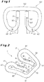
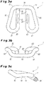
- FIGS Figures 3a, 3b and 3c are further views of the tension clamp 1 according to this embodiment.
- the tension clamp 1 has a middle section, formed from two inner arms 10 and 20, and an outer section, which consists of two torsion sections 30 and 40, two outer arms 50 and 60 and a connecting arm 70 that connects the two outer arms 50, 60 connects with each other, is built up.
- the connecting arm 70 is an example of a rail holding section which, in the assembled state of the tensioning clamp 1, exerts a holding force on the rail to be fastened.
- the various sections of the tension clamp 1 merge into one another in a continuous and curved manner, so that a one-piece, W-shaped spring element is formed.
- the structure of the tension clamp 1 in the plan view of FIG Figure 3a is in detail as follows: Starting from an inner end 11 of the one inner arm 10, the inner arm 10 extends along a direction which is determined by a possible rail (in the Figure 2 not shown) leads away. The inner arm 10 is followed by the torsion section 30 which, when bent outward, passes through an apex 31 and, when bent, merges into the outer arm 50, which is in the In the present exemplary embodiment, it is not exactly parallel, but approximately in the direction of the inner arm 10 goes back beyond the inner end 11 and merges into the connecting arm 70 at an outer deflection point 51. In the assembled state of the tensioning clamp 1, the connecting arm 70 runs parallel to the rail and presses on a rail foot in order to brace the rail.
- the inner arm 20 is followed by the torsion section 40 which, when bent outwards, passes through an apex 41 and continues bent over into the outer arm 60, which in the present exemplary embodiment is not exactly parallel, but approximately in the direction of the inner arm 20 over the inner one End 21 leads back out and merges into the connecting arm 70 at an outer deflection point 61.
- the structure, in particular the deflection points 51, 61 and vertices 31, 41 have in the plan view of Figure 3a roughly the shape of a trapezoid.
- the shape may vary from that in the Figures 2 , 3a to 3c the shape shown.
- the two outer arms 50 and 60 can run parallel.
- the connecting arm 70 can possibly be dispensed with if the rail holding section of the tensioning clamp 1 is constructed in a different way, in particular if the two inner arms 10, 20 have no ends 11, 21 but are connected to one another in their place.
- the tension clamp 1 is designed to be mirror-symmetrical relative to a mirror plane which is perpendicular to the extension of the connecting arm 70 and runs centrally between the two inner arms 10, 20.
- the two inner arms 10, 20 each have a flattened surface 12 and 22, which can be used for direct or indirect (e.g. by means of a washer) Support of the head of a tensioning screw for tensioning the tensioning clamp 1 in the final assembly position are provided (cf. Figures 4, 5 and 6th ).
- the tension clamp 1 rests in the final assembly position at a first support point 13, 23 on a base (described below).
- the two inner arms 10, 20 each have a second support point 14, 24, likewise on the underside of the tensioning clamp 1 (seen in the final assembly position) and also to rest on the base.
- the two support points 13, 14 are in the plan view of Figure 3a essentially on a line which is perpendicular to the connecting arm 70 or a rail to be braced.
- the two support points 13, 14 have essentially no offset. They both lie on the straight extension direction of the respective inner arm 10, 20.
- the torsion sections 30, 40 have no points of support.
- the sections of the inner arms 10, 20, which are located between the two support points 14, 24, are preferably "free", ie they are not in contact with the base, so that the tension clamp 1 is deformed during final assembly by tightening the tensioning screw and can be tensioned in this way. Since the two support points 13, 14 (analogous to 23, 24) have no lateral offset, when tensioning the tension clamp 1, no or a significantly reduced torsional moment acts on the inner arms 10 and 20. This leads to an improved wear behavior of both the tension clamp 1 and the tensioning screw.
- the special arrangement of the support points 13, 14, 23, 24 is preferably achieved in that the inner arms 10, 20 are each bent in a plane that runs parallel to the mirror plane defined above and the corresponding inner arm 10, 20 (more precisely, its center line) contains.
- the inner arms 10, 20 are preferably bent in an S-shape in this regard, as in FIG Figure 3c shown.
- the Figures 4 to 6 show the final assembly position of the tension clamp 1 as part of a non-positive, elastic rail fastening system.
- the Figure 4 is a schematic plan view and shows a rail 2 with a rail foot 2a, which is clamped on both sides by means of a tension clamp 1.
- the rail 2 lies in a recess 3a (cf. Figure 5 ) a sleeper 3 (or another suitable rail pad).
- the rail fastening system has an angled guide plate 4 which is screwed onto the sleeper 3 with a clamping screw 5 each.
- the non-positive, elastic mounting of the rail foot 2a takes place via the tensioning clamp 1 set out above, which is also braced by the tensioning screw 5 via a washer 5a.
- the angled guide plate 4 has a support surface which is set up for the support points of the tensioning clamp 1, in particular for supporting the support points 13, 23, 14, 24.
- the tensioning screw 5 is tightened with a preliminary tightening torque, for example approx. 50 Nm, and the tensioning clamp 1 is in a position set back from the rail 2.
- the tension clamp 1 is brought from the preassembly position towards the rail 2 into the final assembly position, the tension clamp 1 is in a position that consists of the Figures 4 to 6 emerges.
- the clamping screw 5 comes into contact with the flattened surfaces 12, 22 of the two inner arms 10, 20 via the washer 5a, and the connecting arm 70 slides over the rail foot 2a.
- the two inner arms 10, 20 of the tension clamp 1 come to lie at a small distance from the rail foot 2a (or come into contact with it), whereby a tilt protection is given.
- the tensioning screw 5 is then tightened with the final tightening torque, so that the tensioning clamp 1 is tensioned and the connecting arm 70 presses the rail foot 2a with the desired force.
- a separate insulation 7 is provided between the tension clamp 1 and the angled guide plate 4 and the rail foot 2a.
- the electrical insulation 7 is made of plastic, for example, which is preferably molded on or around it, as a result of which the tensioning clamp 1 is at least partially surrounded by the insulation.
- the rail fastening system is particularly suitable for covered tracks that are primarily used in local traffic.
- the background to this is the increased problem of stray current in this area.
- the rail fastening system can be designed to be particularly flat, as a result of which any asphalt pavement above it can be made particularly thick and load-bearing. Due to the large contact surface of the tension clamp 1 on the rail foot 2a, which is ensured by the connecting arm 70, an insulator section can be implemented as part of the above-mentioned insulation 7 between the rail foot 2a and the tension clamp 1 without major wear.
- the angled guide plate 4 can be equipped with a grooved section or a grooved plate 8. What a toothing of this type can look like is particularly clear from the Figure 6 emerged.
Landscapes
- Engineering & Computer Science (AREA)
- Mechanical Engineering (AREA)
- Architecture (AREA)
- Civil Engineering (AREA)
- Structural Engineering (AREA)
- Clamps And Clips (AREA)
Priority Applications (1)
| Application Number | Priority Date | Filing Date | Title |
|---|---|---|---|
| PL18151073T PL3346054T3 (pl) | 2017-01-10 | 2018-01-10 | Łapka sprężysta i system mocowania szyn do mocowania szyn kolejowych |
Applications Claiming Priority (1)
| Application Number | Priority Date | Filing Date | Title |
|---|---|---|---|
| DE102017200268 | 2017-01-10 |
Publications (2)
| Publication Number | Publication Date |
|---|---|
| EP3346054A1 EP3346054A1 (de) | 2018-07-11 |
| EP3346054B1 true EP3346054B1 (de) | 2021-12-01 |
Family
ID=60954906
Family Applications (1)
| Application Number | Title | Priority Date | Filing Date |
|---|---|---|---|
| EP18151073.6A Revoked EP3346054B1 (de) | 2017-01-10 | 2018-01-10 | Spannklemme und schienenbefestigungssystem zur befestigung von eisenbahnschienen |
Country Status (7)
| Country | Link |
|---|---|
| EP (1) | EP3346054B1 (pl) |
| DK (1) | DK3346054T3 (pl) |
| ES (1) | ES2907239T3 (pl) |
| HU (1) | HUE057610T2 (pl) |
| LT (1) | LT3346054T (pl) |
| PL (1) | PL3346054T3 (pl) |
| PT (1) | PT3346054T (pl) |
Families Citing this family (1)
| Publication number | Priority date | Publication date | Assignee | Title |
|---|---|---|---|---|
| CN112442925A (zh) * | 2020-12-31 | 2021-03-05 | 米建军 | 一种轨道弹条及轨道扣件组件 |
Citations (33)
| Publication number | Priority date | Publication date | Assignee | Title |
|---|---|---|---|---|
| DE1020046B (de) | 1955-04-05 | 1957-11-28 | Vossloh Werke Gmbh | Schienenbefestigung auf Schwellen, insbesondere Betonschwellen |
| GB801912A (en) | 1955-12-13 | 1958-09-24 | Sonneville Roger P | Improvements in and relating to rail fixing and supporting devices ensuring insulation of the rail |
| DE1053016B (de) | 1957-02-16 | 1959-03-19 | Vossloh Werke Gmbh | Befestigung seitlich durch Rippen gehaltener Eisenbahnschienen mittels in die Rippen eingreifender federnder Spannbuegel |
| DE1146086B (de) | 1961-06-29 | 1963-03-28 | Kloeckner Werke Ag | Spannbuegelbefestigung fuer Eisenbahnschienen |
| DE1261151B (de) | 1966-10-29 | 1968-02-15 | Meier Hermann Dr Ing | Schienenbefestigung mittels elastischer Klemme |
| DE1534074B1 (de) | 1965-04-07 | 1970-12-03 | Robert Leyer Pritzkow & Co | Schienenbefestigung unter Verwendung von den Schienenfuss niederhaltenden Federbuegeln |
| GB1336862A (en) | 1970-11-13 | 1973-11-14 | Res Designs Standards Org | Device for holding down a railway rail to the sleeper |
| US4053107A (en) | 1975-03-24 | 1977-10-11 | Lodewijk Goderbauer | Device for fastening a rail to a sleeper, holder and clip for the application of such a fastening device |
| GB2077819A (en) | 1980-06-18 | 1981-12-23 | Pandrol Ltd | Fastening railway rails |
| DE3136485A1 (de) | 1981-09-15 | 1983-03-31 | Portec, Inc., 60521 Oak Brook, Ill. | Anordnung zum befestigen einer schiene auf einer schwelle |
| EP0129278A1 (fr) | 1983-06-15 | 1984-12-27 | Usines Emile Henricot | Pièce pour fixation de rail et son procédé de fabrication |
| EP0295685A1 (de) | 1987-06-19 | 1988-12-21 | Vossloh-Werke GmbH | Vorrichtung zur Befestigung von Eisenbahn-Schienen auf fester Fahrbahn |
| EP0373099A1 (fr) | 1988-12-02 | 1990-06-13 | ETABLISSEMENTS VAPE (Sté anonyme) | Bride de fixation rapide d'un rail de chemin de fer et traverse munie d'une telle bride |
| EP0468945A1 (en) | 1990-07-19 | 1992-01-29 | Gerhard Seeger | Clamping means and sleeper assembly |
| EP0503734A1 (en) | 1991-03-12 | 1992-09-16 | NUOVE OFFICINE MECCANICHE CINEL S.p.A. | Spring attachment construction, especially suited for locking railtracking |
| EP0694649A2 (en) | 1994-07-27 | 1996-01-31 | NUOVE OFFICINE MECCANICHE CINEL S.p.A. | A resilient connecting device |
| DE19642971A1 (de) | 1996-03-09 | 1997-09-11 | Krupp Ag Hoesch Krupp | Federnde Schienenbefestigung |
| WO1997036055A1 (en) | 1996-03-27 | 1997-10-02 | Pandrol Limited | Railway rail fastening assemblies including resilient railway rail fastening clips and associated insulators |
| WO2000022235A1 (en) | 1998-10-14 | 2000-04-20 | Igwemezie Jude O | Rail retaining device |
| WO2006061234A1 (de) | 2004-12-09 | 2006-06-15 | Schwihag Ag | Kraftschlüssig-elastische schienbefestigung für gleisangen |
| WO2008003340A1 (de) | 2006-07-05 | 2008-01-10 | Transroad Group (Uk) Limited | Federklemme für eine vorrichtung zur befestigung einer eisenbahnschiene auf einer schwelle |
| DE202007018500U1 (de) | 2007-02-19 | 2008-08-14 | Vossloh-Werke Gmbh | Isolier-Clip sowie System zum Befestigung einer Schiene für Schienenfahrzeuge |
| WO2011020795A1 (en) | 2009-08-21 | 2011-02-24 | Pandrol Limited | Insulator for railway fastening clip and railway rail fastening clip for use therewith |
| CN201972058U (zh) | 2011-02-17 | 2011-09-14 | 济南铁路局淄博工务工厂 | 绝缘弹条 |
| WO2012025201A1 (de) | 2010-08-27 | 2012-03-01 | Schwihag Ag | Schienenbefestigungssystem |
| WO2012059318A1 (de) | 2010-11-04 | 2012-05-10 | Vossloh-Werke Gmbh | Spannklemme zum befestigen einer schiene und mit einer solchen spannklemme ausgestattetes system |
| WO2013160760A1 (en) | 2012-04-23 | 2013-10-31 | Amsted Rail Co, Inc | Improved rail clip |
| EP2386687B1 (de) | 2010-05-10 | 2013-11-20 | Vossloh-Werke GmbH | Führungsplatte zum seitlichen Führen einer Schiene und System zum Befestigen einer Schiene auf einem Untergrund |
| EP2245226B1 (de) | 2008-02-22 | 2015-06-10 | Vossloh-Werke GmbH | System zum Befestigen einer Schiene auf einem Untergrund |
| CN105064143A (zh) | 2015-09-22 | 2015-11-18 | 京投银泰股份有限公司 | 钢轨减振扣件 |
| CN205603975U (zh) | 2016-04-26 | 2016-09-28 | 济南铁路局淄博工务工厂 | 防腐弹条 |
| RU2624765C1 (ru) | 2016-02-02 | 2017-07-06 | Виктор Акимович Воронов | Рельсовое скрепление |
| CN107130477A (zh) | 2017-05-19 | 2017-09-05 | 江苏海迅实业集团股份有限公司 | 一种绝缘防腐弹条 |
Family Cites Families (2)
| Publication number | Priority date | Publication date | Assignee | Title |
|---|---|---|---|---|
| WO2003046285A2 (de) * | 2001-11-30 | 2003-06-05 | Vossloh-Werke Gmbh | Federelement zum verspannen von schienen für schienenfahrzeuge |
| EP2410090B1 (de) | 2010-07-19 | 2015-03-11 | Schwihag Ag | Schienenbefestigungssystem |
-
2018
- 2018-01-10 PL PL18151073T patent/PL3346054T3/pl unknown
- 2018-01-10 ES ES18151073T patent/ES2907239T3/es active Active
- 2018-01-10 DK DK18151073.6T patent/DK3346054T3/da active
- 2018-01-10 EP EP18151073.6A patent/EP3346054B1/de not_active Revoked
- 2018-01-10 HU HUE18151073A patent/HUE057610T2/hu unknown
- 2018-01-10 LT LTEP18151073.6T patent/LT3346054T/lt unknown
- 2018-01-10 PT PT181510736T patent/PT3346054T/pt unknown
Patent Citations (33)
| Publication number | Priority date | Publication date | Assignee | Title |
|---|---|---|---|---|
| DE1020046B (de) | 1955-04-05 | 1957-11-28 | Vossloh Werke Gmbh | Schienenbefestigung auf Schwellen, insbesondere Betonschwellen |
| GB801912A (en) | 1955-12-13 | 1958-09-24 | Sonneville Roger P | Improvements in and relating to rail fixing and supporting devices ensuring insulation of the rail |
| DE1053016B (de) | 1957-02-16 | 1959-03-19 | Vossloh Werke Gmbh | Befestigung seitlich durch Rippen gehaltener Eisenbahnschienen mittels in die Rippen eingreifender federnder Spannbuegel |
| DE1146086B (de) | 1961-06-29 | 1963-03-28 | Kloeckner Werke Ag | Spannbuegelbefestigung fuer Eisenbahnschienen |
| DE1534074B1 (de) | 1965-04-07 | 1970-12-03 | Robert Leyer Pritzkow & Co | Schienenbefestigung unter Verwendung von den Schienenfuss niederhaltenden Federbuegeln |
| DE1261151B (de) | 1966-10-29 | 1968-02-15 | Meier Hermann Dr Ing | Schienenbefestigung mittels elastischer Klemme |
| GB1336862A (en) | 1970-11-13 | 1973-11-14 | Res Designs Standards Org | Device for holding down a railway rail to the sleeper |
| US4053107A (en) | 1975-03-24 | 1977-10-11 | Lodewijk Goderbauer | Device for fastening a rail to a sleeper, holder and clip for the application of such a fastening device |
| GB2077819A (en) | 1980-06-18 | 1981-12-23 | Pandrol Ltd | Fastening railway rails |
| DE3136485A1 (de) | 1981-09-15 | 1983-03-31 | Portec, Inc., 60521 Oak Brook, Ill. | Anordnung zum befestigen einer schiene auf einer schwelle |
| EP0129278A1 (fr) | 1983-06-15 | 1984-12-27 | Usines Emile Henricot | Pièce pour fixation de rail et son procédé de fabrication |
| EP0295685A1 (de) | 1987-06-19 | 1988-12-21 | Vossloh-Werke GmbH | Vorrichtung zur Befestigung von Eisenbahn-Schienen auf fester Fahrbahn |
| EP0373099A1 (fr) | 1988-12-02 | 1990-06-13 | ETABLISSEMENTS VAPE (Sté anonyme) | Bride de fixation rapide d'un rail de chemin de fer et traverse munie d'une telle bride |
| EP0468945A1 (en) | 1990-07-19 | 1992-01-29 | Gerhard Seeger | Clamping means and sleeper assembly |
| EP0503734A1 (en) | 1991-03-12 | 1992-09-16 | NUOVE OFFICINE MECCANICHE CINEL S.p.A. | Spring attachment construction, especially suited for locking railtracking |
| EP0694649A2 (en) | 1994-07-27 | 1996-01-31 | NUOVE OFFICINE MECCANICHE CINEL S.p.A. | A resilient connecting device |
| DE19642971A1 (de) | 1996-03-09 | 1997-09-11 | Krupp Ag Hoesch Krupp | Federnde Schienenbefestigung |
| WO1997036055A1 (en) | 1996-03-27 | 1997-10-02 | Pandrol Limited | Railway rail fastening assemblies including resilient railway rail fastening clips and associated insulators |
| WO2000022235A1 (en) | 1998-10-14 | 2000-04-20 | Igwemezie Jude O | Rail retaining device |
| WO2006061234A1 (de) | 2004-12-09 | 2006-06-15 | Schwihag Ag | Kraftschlüssig-elastische schienbefestigung für gleisangen |
| WO2008003340A1 (de) | 2006-07-05 | 2008-01-10 | Transroad Group (Uk) Limited | Federklemme für eine vorrichtung zur befestigung einer eisenbahnschiene auf einer schwelle |
| DE202007018500U1 (de) | 2007-02-19 | 2008-08-14 | Vossloh-Werke Gmbh | Isolier-Clip sowie System zum Befestigung einer Schiene für Schienenfahrzeuge |
| EP2245226B1 (de) | 2008-02-22 | 2015-06-10 | Vossloh-Werke GmbH | System zum Befestigen einer Schiene auf einem Untergrund |
| WO2011020795A1 (en) | 2009-08-21 | 2011-02-24 | Pandrol Limited | Insulator for railway fastening clip and railway rail fastening clip for use therewith |
| EP2386687B1 (de) | 2010-05-10 | 2013-11-20 | Vossloh-Werke GmbH | Führungsplatte zum seitlichen Führen einer Schiene und System zum Befestigen einer Schiene auf einem Untergrund |
| WO2012025201A1 (de) | 2010-08-27 | 2012-03-01 | Schwihag Ag | Schienenbefestigungssystem |
| WO2012059318A1 (de) | 2010-11-04 | 2012-05-10 | Vossloh-Werke Gmbh | Spannklemme zum befestigen einer schiene und mit einer solchen spannklemme ausgestattetes system |
| CN201972058U (zh) | 2011-02-17 | 2011-09-14 | 济南铁路局淄博工务工厂 | 绝缘弹条 |
| WO2013160760A1 (en) | 2012-04-23 | 2013-10-31 | Amsted Rail Co, Inc | Improved rail clip |
| CN105064143A (zh) | 2015-09-22 | 2015-11-18 | 京投银泰股份有限公司 | 钢轨减振扣件 |
| RU2624765C1 (ru) | 2016-02-02 | 2017-07-06 | Виктор Акимович Воронов | Рельсовое скрепление |
| CN205603975U (zh) | 2016-04-26 | 2016-09-28 | 济南铁路局淄博工务工厂 | 防腐弹条 |
| CN107130477A (zh) | 2017-05-19 | 2017-09-05 | 江苏海迅实业集团股份有限公司 | 一种绝缘防腐弹条 |
Also Published As
| Publication number | Publication date |
|---|---|
| LT3346054T (lt) | 2022-01-25 |
| HUE057610T2 (hu) | 2022-05-28 |
| PL3346054T3 (pl) | 2022-03-28 |
| DK3346054T3 (da) | 2022-01-31 |
| ES2907239T3 (es) | 2022-04-22 |
| PT3346054T (pt) | 2022-01-19 |
| EP3346054A1 (de) | 2018-07-11 |
Similar Documents
| Publication | Publication Date | Title |
|---|---|---|
| EP0295685B1 (de) | Vorrichtung zur Befestigung von Eisenbahn-Schienen auf fester Fahrbahn | |
| EP1974100B1 (de) | System zur befestigung einer schiene | |
| EP2478154B1 (de) | System zum Befestigen einer Schiene | |
| EP2386687B1 (de) | Führungsplatte zum seitlichen Führen einer Schiene und System zum Befestigen einer Schiene auf einem Untergrund | |
| EP2191069B1 (de) | System zum befestigen einer schiene und spannklemme für ein solches system | |
| EP2318589A1 (de) | Vorrichtung zur befestigung von eisenbahnschienen auf einer unterkonstruktion | |
| DD249059A5 (de) | Schienenbefestigung mittels einer elastischen spannklemme | |
| DE68904177T2 (de) | Schnellbefestigung fuer eisenbahnschienen und schwelle mit solcher befestigung. | |
| DE3400110C2 (pl) | ||
| WO2012016640A2 (de) | Stromschienenanordnung | |
| WO2012059374A1 (de) | Spannklemme zum befestigen einer schiene und mit einer solchen spannklemme ausgestattetes system | |
| EP2297402B9 (de) | System zum befestigen einer schiene auf einem untergrund | |
| CH656161A5 (de) | Vorrichtung zum federnden befestigen einer schiene auf einer betonschwelle. | |
| EP3346054B1 (de) | Spannklemme und schienenbefestigungssystem zur befestigung von eisenbahnschienen | |
| DE202011050739U1 (de) | System zum Befestigen einer Schiene auf einem Untergrund | |
| EP0338124B1 (de) | Fahrbahnübergang | |
| DE3003881A1 (de) | Spannbuegel fuer kraftschluessige und elastisch nachgiebige schienenbefestigungen mit formschluessigem seitenhalt von gleisanlagen | |
| EP2609255B1 (de) | Schienenbefestigungssystem | |
| WO2017054998A1 (de) | System und befestigungspunkt zum schraubenlosen befestigen einer schiene für ein schienenfahrzeug | |
| DE3003867A1 (de) | Kraftschluessige und elastisch nachgiebige schienenbefestigung fuer gleisanlagen | |
| EP3501863B1 (de) | Begehbare bodeneinrichtung für einen übergang | |
| AT12657U1 (de) | System zum befestigen einer schiene auf einem untergrund | |
| EP4624662A2 (de) | Spannfeder zum niederhalten eines gleiskörperelements | |
| WO2007065515A1 (de) | Befestigungsmittel zur befestigung von bahnschienen auf gleisschwellen oder gleisfahrwegen | |
| DE29913894U1 (de) | Fahrdrahtkreuzung |
Legal Events
| Date | Code | Title | Description |
|---|---|---|---|
| PUAI | Public reference made under article 153(3) epc to a published international application that has entered the european phase |
Free format text: ORIGINAL CODE: 0009012 |
|
| STAA | Information on the status of an ep patent application or granted ep patent |
Free format text: STATUS: THE APPLICATION HAS BEEN PUBLISHED |
|
| AK | Designated contracting states |
Kind code of ref document: A1 Designated state(s): AL AT BE BG CH CY CZ DE DK EE ES FI FR GB GR HR HU IE IS IT LI LT LU LV MC MK MT NL NO PL PT RO RS SE SI SK SM TR |
|
| AX | Request for extension of the european patent |
Extension state: BA ME |
|
| STAA | Information on the status of an ep patent application or granted ep patent |
Free format text: STATUS: REQUEST FOR EXAMINATION WAS MADE |
|
| 17P | Request for examination filed |
Effective date: 20181219 |
|
| RBV | Designated contracting states (corrected) |
Designated state(s): AL AT BE BG CH CY CZ DE DK EE ES FI FR GB GR HR HU IE IS IT LI LT LU LV MC MK MT NL NO PL PT RO RS SE SI SK SM TR |
|
| STAA | Information on the status of an ep patent application or granted ep patent |
Free format text: STATUS: EXAMINATION IS IN PROGRESS |
|
| 17Q | First examination report despatched |
Effective date: 20190628 |
|
| GRAP | Despatch of communication of intention to grant a patent |
Free format text: ORIGINAL CODE: EPIDOSNIGR1 |
|
| STAA | Information on the status of an ep patent application or granted ep patent |
Free format text: STATUS: GRANT OF PATENT IS INTENDED |
|
| RIC1 | Information provided on ipc code assigned before grant |
Ipc: E01B 9/48 20060101ALN20210428BHEP Ipc: E01B 9/30 20060101AFI20210428BHEP |
|
| INTG | Intention to grant announced |
Effective date: 20210527 |
|
| GRAS | Grant fee paid |
Free format text: ORIGINAL CODE: EPIDOSNIGR3 |
|
| GRAA | (expected) grant |
Free format text: ORIGINAL CODE: 0009210 |
|
| STAA | Information on the status of an ep patent application or granted ep patent |
Free format text: STATUS: THE PATENT HAS BEEN GRANTED |
|
| AK | Designated contracting states |
Kind code of ref document: B1 Designated state(s): AL AT BE BG CH CY CZ DE DK EE ES FI FR GB GR HR HU IE IS IT LI LT LU LV MC MK MT NL NO PL PT RO RS SE SI SK SM TR |
|
| RAP3 | Party data changed (applicant data changed or rights of an application transferred) |
Owner name: SCHWIHAG AG |
|
| REG | Reference to a national code |
Ref country code: GB Ref legal event code: FG4D Free format text: NOT ENGLISH |
|
| REG | Reference to a national code |
Ref country code: AT Ref legal event code: REF Ref document number: 1451861 Country of ref document: AT Kind code of ref document: T Effective date: 20211215 Ref country code: CH Ref legal event code: EP |
|
| REG | Reference to a national code |
Ref country code: DE Ref legal event code: R096 Ref document number: 502018008008 Country of ref document: DE |
|
| REG | Reference to a national code |
Ref country code: IE Ref legal event code: FG4D Free format text: LANGUAGE OF EP DOCUMENT: GERMAN |
|
| REG | Reference to a national code |
Ref country code: PT Ref legal event code: SC4A Ref document number: 3346054 Country of ref document: PT Date of ref document: 20220119 Kind code of ref document: T Free format text: AVAILABILITY OF NATIONAL TRANSLATION Effective date: 20220112 |
|
| REG | Reference to a national code |
Ref country code: DK Ref legal event code: T3 Effective date: 20220127 |
|
| REG | Reference to a national code |
Ref country code: FI Ref legal event code: FGE |
|
| REG | Reference to a national code |
Ref country code: RO Ref legal event code: EPE |
|
| REG | Reference to a national code |
Ref country code: NL Ref legal event code: FP |
|
| REG | Reference to a national code |
Ref country code: SE Ref legal event code: TRGR |
|
| REG | Reference to a national code |
Ref country code: GR Ref legal event code: EP Ref document number: 20220400191 Country of ref document: GR Effective date: 20220309 |
|
| REG | Reference to a national code |
Ref country code: ES Ref legal event code: FG2A Ref document number: 2907239 Country of ref document: ES Kind code of ref document: T3 Effective date: 20220422 |
|
| PG25 | Lapsed in a contracting state [announced via postgrant information from national office to epo] |
Ref country code: RS Free format text: LAPSE BECAUSE OF FAILURE TO SUBMIT A TRANSLATION OF THE DESCRIPTION OR TO PAY THE FEE WITHIN THE PRESCRIBED TIME-LIMIT Effective date: 20211201 Ref country code: BG Free format text: LAPSE BECAUSE OF FAILURE TO SUBMIT A TRANSLATION OF THE DESCRIPTION OR TO PAY THE FEE WITHIN THE PRESCRIBED TIME-LIMIT Effective date: 20220301 |
|
| PGFP | Annual fee paid to national office [announced via postgrant information from national office to epo] |
Ref country code: LT Payment date: 20220111 Year of fee payment: 5 |
|
| REG | Reference to a national code |
Ref country code: NO Ref legal event code: T2 Effective date: 20211201 |
|
| REG | Reference to a national code |
Ref country code: HU Ref legal event code: AG4A Ref document number: E057610 Country of ref document: HU |
|
| PG25 | Lapsed in a contracting state [announced via postgrant information from national office to epo] |
Ref country code: LV Free format text: LAPSE BECAUSE OF FAILURE TO SUBMIT A TRANSLATION OF THE DESCRIPTION OR TO PAY THE FEE WITHIN THE PRESCRIBED TIME-LIMIT Effective date: 20211201 Ref country code: HR Free format text: LAPSE BECAUSE OF FAILURE TO SUBMIT A TRANSLATION OF THE DESCRIPTION OR TO PAY THE FEE WITHIN THE PRESCRIBED TIME-LIMIT Effective date: 20211201 |
|
| PGFP | Annual fee paid to national office [announced via postgrant information from national office to epo] |
Ref country code: PT Payment date: 20220119 Year of fee payment: 5 |
|
| PG25 | Lapsed in a contracting state [announced via postgrant information from national office to epo] |
Ref country code: SM Free format text: LAPSE BECAUSE OF FAILURE TO SUBMIT A TRANSLATION OF THE DESCRIPTION OR TO PAY THE FEE WITHIN THE PRESCRIBED TIME-LIMIT Effective date: 20211201 Ref country code: EE Free format text: LAPSE BECAUSE OF FAILURE TO SUBMIT A TRANSLATION OF THE DESCRIPTION OR TO PAY THE FEE WITHIN THE PRESCRIBED TIME-LIMIT Effective date: 20211201 |
|
| PGFP | Annual fee paid to national office [announced via postgrant information from national office to epo] |
Ref country code: IT Payment date: 20220331 Year of fee payment: 5 |
|
| REG | Reference to a national code |
Ref country code: DE Ref legal event code: R026 Ref document number: 502018008008 Country of ref document: DE |
|
| PG25 | Lapsed in a contracting state [announced via postgrant information from national office to epo] |
Ref country code: MC Free format text: LAPSE BECAUSE OF FAILURE TO SUBMIT A TRANSLATION OF THE DESCRIPTION OR TO PAY THE FEE WITHIN THE PRESCRIBED TIME-LIMIT Effective date: 20211201 |
|
| PLBI | Opposition filed |
Free format text: ORIGINAL CODE: 0009260 |
|
| PLAB | Opposition data, opponent's data or that of the opponent's representative modified |
Free format text: ORIGINAL CODE: 0009299OPPO |
|
| PLAX | Notice of opposition and request to file observation + time limit sent |
Free format text: ORIGINAL CODE: EPIDOSNOBS2 |
|
| PG25 | Lapsed in a contracting state [announced via postgrant information from national office to epo] |
Ref country code: IS Free format text: LAPSE BECAUSE OF FAILURE TO SUBMIT A TRANSLATION OF THE DESCRIPTION OR TO PAY THE FEE WITHIN THE PRESCRIBED TIME-LIMIT Effective date: 20220401 |
|
| REG | Reference to a national code |
Ref country code: FI Ref legal event code: MDE Opponent name: VOESTALPINE RAILWAY SYSTEMS GMBH Ref country code: FI Ref legal event code: MDE Opponent name: VOSSLOH FASTENING SYSTEMS GMBH |
|
| 26 | Opposition filed |
Opponent name: VOESTALPINE RAILWAY SYSTEMS GMBH Effective date: 20220831 Opponent name: VOSSLOH FASTENING SYSTEMS GMBH Effective date: 20220829 |
|
| R26 | Opposition filed (corrected) |
Opponent name: VOESTALPINE RAILWAY SYSTEMS GMBH Effective date: 20220831 |
|
| PG25 | Lapsed in a contracting state [announced via postgrant information from national office to epo] |
Ref country code: AL Free format text: LAPSE BECAUSE OF FAILURE TO SUBMIT A TRANSLATION OF THE DESCRIPTION OR TO PAY THE FEE WITHIN THE PRESCRIBED TIME-LIMIT Effective date: 20211201 |
|
| PG25 | Lapsed in a contracting state [announced via postgrant information from national office to epo] |
Ref country code: SI Free format text: LAPSE BECAUSE OF FAILURE TO SUBMIT A TRANSLATION OF THE DESCRIPTION OR TO PAY THE FEE WITHIN THE PRESCRIBED TIME-LIMIT Effective date: 20211201 |
|
| PLAF | Information modified related to communication of a notice of opposition and request to file observations + time limit |
Free format text: ORIGINAL CODE: EPIDOSCOBS2 |
|
| PG25 | Lapsed in a contracting state [announced via postgrant information from national office to epo] |
Ref country code: IT Free format text: LAPSE BECAUSE OF NON-PAYMENT OF DUE FEES Effective date: 20220110 Ref country code: IE Free format text: LAPSE BECAUSE OF NON-PAYMENT OF DUE FEES Effective date: 20220110 |
|
| PLBB | Reply of patent proprietor to notice(s) of opposition received |
Free format text: ORIGINAL CODE: EPIDOSNOBS3 |
|
| P01 | Opt-out of the competence of the unified patent court (upc) registered |
Effective date: 20230517 |
|
| REG | Reference to a national code |
Ref country code: LT Ref legal event code: MM4D Effective date: 20230110 |
|
| PGFP | Annual fee paid to national office [announced via postgrant information from national office to epo] |
Ref country code: LU Payment date: 20230629 Year of fee payment: 6 Ref country code: GR Payment date: 20230630 Year of fee payment: 6 |
|
| PG25 | Lapsed in a contracting state [announced via postgrant information from national office to epo] |
Ref country code: PT Free format text: LAPSE BECAUSE OF NON-PAYMENT OF DUE FEES Effective date: 20230710 |
|
| PG25 | Lapsed in a contracting state [announced via postgrant information from national office to epo] |
Ref country code: LT Free format text: LAPSE BECAUSE OF NON-PAYMENT OF DUE FEES Effective date: 20230110 |
|
| PG25 | Lapsed in a contracting state [announced via postgrant information from national office to epo] |
Ref country code: MK Free format text: LAPSE BECAUSE OF FAILURE TO SUBMIT A TRANSLATION OF THE DESCRIPTION OR TO PAY THE FEE WITHIN THE PRESCRIBED TIME-LIMIT Effective date: 20211201 Ref country code: CY Free format text: LAPSE BECAUSE OF FAILURE TO SUBMIT A TRANSLATION OF THE DESCRIPTION OR TO PAY THE FEE WITHIN THE PRESCRIBED TIME-LIMIT Effective date: 20211201 |
|
| PGFP | Annual fee paid to national office [announced via postgrant information from national office to epo] |
Ref country code: CZ Payment date: 20240524 Year of fee payment: 7 |
|
| PGFP | Annual fee paid to national office [announced via postgrant information from national office to epo] |
Ref country code: SK Payment date: 20240527 Year of fee payment: 7 |
|
| PGFP | Annual fee paid to national office [announced via postgrant information from national office to epo] |
Ref country code: RO Payment date: 20240529 Year of fee payment: 7 |
|
| PGFP | Annual fee paid to national office [announced via postgrant information from national office to epo] |
Ref country code: PL Payment date: 20240524 Year of fee payment: 7 |
|
| PLAB | Opposition data, opponent's data or that of the opponent's representative modified |
Free format text: ORIGINAL CODE: 0009299OPPO |
|
| PGFP | Annual fee paid to national office [announced via postgrant information from national office to epo] |
Ref country code: TR Payment date: 20240531 Year of fee payment: 7 Ref country code: HU Payment date: 20240606 Year of fee payment: 7 |
|
| PGFP | Annual fee paid to national office [announced via postgrant information from national office to epo] |
Ref country code: NL Payment date: 20240726 Year of fee payment: 7 |
|
| R26 | Opposition filed (corrected) |
Opponent name: VOESTALPINE RAILWAY SYSTEMS GMBH Effective date: 20220831 |
|
| PG25 | Lapsed in a contracting state [announced via postgrant information from national office to epo] |
Ref country code: LU Free format text: LAPSE BECAUSE OF NON-PAYMENT OF DUE FEES Effective date: 20240110 |
|
| PG25 | Lapsed in a contracting state [announced via postgrant information from national office to epo] |
Ref country code: MT Free format text: LAPSE BECAUSE OF FAILURE TO SUBMIT A TRANSLATION OF THE DESCRIPTION OR TO PAY THE FEE WITHIN THE PRESCRIBED TIME-LIMIT Effective date: 20211201 Ref country code: LU Free format text: LAPSE BECAUSE OF NON-PAYMENT OF DUE FEES Effective date: 20240110 |
|
| PGFP | Annual fee paid to national office [announced via postgrant information from national office to epo] |
Ref country code: DE Payment date: 20240730 Year of fee payment: 7 Ref country code: FI Payment date: 20240725 Year of fee payment: 7 |
|
| PG25 | Lapsed in a contracting state [announced via postgrant information from national office to epo] |
Ref country code: GR Free format text: LAPSE BECAUSE OF NON-PAYMENT OF DUE FEES Effective date: 20240802 |
|
| PGFP | Annual fee paid to national office [announced via postgrant information from national office to epo] |
Ref country code: DK Payment date: 20240730 Year of fee payment: 7 |
|
| PGFP | Annual fee paid to national office [announced via postgrant information from national office to epo] |
Ref country code: GB Payment date: 20240730 Year of fee payment: 7 |
|
| PGFP | Annual fee paid to national office [announced via postgrant information from national office to epo] |
Ref country code: BE Payment date: 20240726 Year of fee payment: 7 |
|
| PGFP | Annual fee paid to national office [announced via postgrant information from national office to epo] |
Ref country code: FR Payment date: 20240730 Year of fee payment: 7 |
|
| PGFP | Annual fee paid to national office [announced via postgrant information from national office to epo] |
Ref country code: CH Payment date: 20240725 Year of fee payment: 7 Ref country code: ES Payment date: 20240725 Year of fee payment: 7 |
|
| PGFP | Annual fee paid to national office [announced via postgrant information from national office to epo] |
Ref country code: AT Payment date: 20240726 Year of fee payment: 7 |
|
| PG25 | Lapsed in a contracting state [announced via postgrant information from national office to epo] |
Ref country code: GR Free format text: LAPSE BECAUSE OF NON-PAYMENT OF DUE FEES Effective date: 20240802 |
|
| PGFP | Annual fee paid to national office [announced via postgrant information from national office to epo] |
Ref country code: NO Payment date: 20240731 Year of fee payment: 7 Ref country code: SE Payment date: 20240730 Year of fee payment: 7 |
|
| REG | Reference to a national code |
Ref country code: DE Ref legal event code: R103 Ref document number: 502018008008 Country of ref document: DE Ref country code: DE Ref legal event code: R064 Ref document number: 502018008008 Country of ref document: DE |
|
| RDAF | Communication despatched that patent is revoked |
Free format text: ORIGINAL CODE: EPIDOSNREV1 |
|
| RDAG | Patent revoked |
Free format text: ORIGINAL CODE: 0009271 |
|
| STAA | Information on the status of an ep patent application or granted ep patent |
Free format text: STATUS: PATENT REVOKED |
|
| REG | Reference to a national code |
Ref country code: CH Ref legal event code: PL |
|
| 27W | Patent revoked |
Effective date: 20241112 |
|
| GBPR | Gb: patent revoked under art. 102 of the ep convention designating the uk as contracting state |
Effective date: 20241112 |
|
| REG | Reference to a national code |
Ref country code: SK Ref legal event code: MC4A Ref document number: E 39372 Country of ref document: SK Effective date: 20241112 |
|
| REG | Reference to a national code |
Ref country code: AT Ref legal event code: MA03 Ref document number: 1451861 Country of ref document: AT Kind code of ref document: T Effective date: 20241112 |
|
| REG | Reference to a national code |
Ref country code: SE Ref legal event code: ECNC |