EP3346065A1 - Toilettes à chasse d'eau - Google Patents
Toilettes à chasse d'eau Download PDFInfo
- Publication number
- EP3346065A1 EP3346065A1 EP16841290.6A EP16841290A EP3346065A1 EP 3346065 A1 EP3346065 A1 EP 3346065A1 EP 16841290 A EP16841290 A EP 16841290A EP 3346065 A1 EP3346065 A1 EP 3346065A1
- Authority
- EP
- European Patent Office
- Prior art keywords
- shelf
- water
- inclined surface
- discharge port
- flush
- Prior art date
- Legal status (The legal status is an assumption and is not a legal conclusion. Google has not performed a legal analysis and makes no representation as to the accuracy of the status listed.)
- Granted
Links
Images






Classifications
-
- E—FIXED CONSTRUCTIONS
- E03—WATER SUPPLY; SEWERAGE
- E03D—WATER-CLOSETS OR URINALS WITH FLUSHING DEVICES; FLUSHING VALVES THEREFOR
- E03D11/00—Other component parts of water-closets, e.g. noise-reducing means in the flushing system, flushing pipes mounted in the bowl, seals for the bowl outlet, devices preventing overflow of the bowl contents; devices forming a water seal in the bowl after flushing, devices eliminating obstructions in the bowl outlet or preventing backflow of water and excrements from the waterpipe
- E03D11/02—Water-closet bowls ; Bowls with a double odour seal optionally with provisions for a good siphonic action; siphons as part of the bowl
- E03D11/08—Bowls with means producing a flushing water swirl
Definitions
- the present invention relates to a flush toilet, and in particular relates to a type of flush toilet in which the toilet bowl is flushed with a swirling flow of water.
- flushing For a flush toilet, a flushing method is known in which flush water is discharged through one or more discharge ports into the toilet bowl part, and waste is pushed out to a drain pipe by means of the flow of the flush water.
- the force of pushing waste out from the inside of the toilet to the drain pipe will be referred to as the "draining force”.
- a flow of water is required to flush a wide range of the inner wall surface of the toilet bowl part.
- flushing force the force of flushing the inner wall of a toilet bowl
- Patent Document 1 In recent years, a functional unit, such as a pubic lavage device and a warm air device, is often provided in a rear part of a flush toilet.
- a functional unit such as a pubic lavage device and a warm air device
- the nozzle In order to prevent a nozzle or the like of a pubic lavage device from getting dirty, the nozzle is covered with a cover member that is nearly flush with the inner wall surface of a rear end part of the toilet bowl.
- dirt of the nozzle is regarded as a problem, it is held that dirt of the cover member for the nozzle is considered on the premise that a user needs to wipe the dirt off (see paragraph [0032] in Patent Document 1) .
- Patent Document 1 Japanese Unexamined Patent Application Publication No. 2010-174451
- flush toilets need to be designed so that the course of flush water can be sophisticatedly changed without weakening the flow of the flush water.
- the flush toilets need to be structured so that a functional unit, such as a pubic lavage device, can be mounted thereon.
- a main purpose of the present invention is to propose new design of a flush toilet for improving the flushing force and the draining force.
- a flush toilet includes: a body part with a toilet bowl part formed therein, including a first upper surface positioned higher and a second upper surface positioned lower; a water conveyance shelf formed along a circumferential direction of the toilet bowl part on an inner wall surface of the toilet bowl part; and a discharge port formed so that water is discharged therethrough to the water conveyance shelf.
- the water conveyance shelf includes a first shelf part formed at a corresponding position of the first upper surface and also includes a second shelf part formed at a corresponding position of the second upper surface.
- the second shelf part is positioned lower than the first shelf part.
- a flush toilet includes: a toilet bowl part; a water conveyance shelf formed along a circumferential direction on an inner wall surface of the toilet bowl part and including a first shelf part positioned higher and a second shelf part positioned lower; a first discharge port formed above the first shelf part; and a second discharge port formed above the second shelf part and positioned lower than the first discharge port.
- the first shelf part and the second shelf part are smoothly connected by a shelf inclined surface.
- the present invention facilitates improvement in the flushing force and the draining force of a flush toilet.
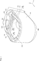
- Fig. 1 is an external perspective view of a flush toilet 100.
- a toilet bowl 106 is formed in a body part 144 of the flush toilet 100. Also, in the body part 144, flush water stored in an external tank is discharged to the toilet bowl 106 through a first discharge port 102 and a second discharge port 104. Part of the flush water is also discharged through a third discharge port, which will be described later in association with Fig. 2 .
- the third discharge port may be a so-called jet discharge port.
- the first discharge port 102 is formed on a side surface (the negative direction side of the y-axis) of the toilet bowl 106.
- the second discharge port 104 is formed on a rear end surface (the negative direction side of the x-axis) of the toilet bowl 106.
- a water conveyance shelf 108 is annularly formed.
- the flush water discharged through the second discharge port 104 (hereinafter, referred to as “second flush water”) flows upon the water conveyance shelf 108, and most of the flush water flows down into the toilet bowl 106 before the first discharge port 102, while the remaining flush water is merged into the flush water discharged through the first discharge port 102 (hereinafter, referred to as "first flush water”).
- the first flush water swirls upon the water conveyance shelf 108, thereby flushing the entirety of the toilet bowl 106, particularly the front surface and the both side surfaces of the inner wall.
- the upper surface of the toilet bowl 106 is formed as a stepped surface including a first upper surface 110 positioned higher and a second upper surface 112 positioned lower.
- the second upper surface 112 in the first embodiment forms a flat bottom surface of a recess part 138 in the upper surface.
- the second upper surface 112 need not necessarily be flat, and it may be formed as a surface curved downward or upward, or a projection or a cutout may be formed in part of the second upper surface 112.
- a functional unit (not illustrated) for providing the pubic lavage function or the warm air function, for example, is mounted on the recess part 138 (upon the second upper surface 112).
- the second upper surface 112 and the first upper surface 110 are smoothly connected by two upper inclined surfaces 140a and 140b, so that an annular upper surface having a height difference is formed.
- the water conveyance shelf 108 includes a first shelf part 114 positioned higher and a second shelf part 116 positioned lower.
- the first shelf part 114 is formed at a corresponding position of the first upper surface 110
- the second shelf part 116 is formed at a corresponding position of the second upper surface 112.
- the "corresponding position” means a position corresponding, in a vertical direction (z-axis direction), to another position and, in other words, it means a position that overlaps another position in plan view.
- first shelf part 114 (higher shelf) is formed so as to correspond to 90 percent or more of the inner peripheral line of the first upper surface 110 (higher surface), and the second shelf part 116 (lower shelf) is formed so as to correspond to 90 percent or more of the inner peripheral line of the second upper surface 112 (lower surface) (see also Fig. 2 ).
- first shelf part 114 is longer than the second shelf part 116.
- a height difference is provided between the first shelf part 114 and the second shelf part 116 in the water conveyance shelf 108 so as to be commensurate with the height difference (step) between the first upper surface 110 and the second upper surface 112 in the upper surface part.
- the first shelf part 114 and the second shelf part 116 are connected by a smooth inclined surface (shelf inclined surface 120a) (which will be detailed in association with Fig. 2 ).
- Shelf inclined surface 120a which will be detailed in association with Fig. 2 .
- Being “smooth" in the present specification means that surfaces are continuously connected with each other, or surfaces are connected with each other without including a discontinuous surface.
- the upper surface (the first upper surface 110, second upper surface 112, and upper inclined surfaces 140a and 140b) extends inward, so as to form an overhang 118 (a rim folded part) over the entire periphery.
- the overhang 118 is, in a manner, a roof for the water conveyance shelf 108, and the water conveyance shelf 108 and the overhang 118 form a water passage.
- the overhang 118 of the first embodiment is annularly formed along the entire inner periphery of the toilet bowl 106.
- the water conveyance shelf 108 excluding part thereof, includes a surface substantially in parallel with the overhang 118 mainly in a horizontal direction (the water flowing direction). More specifically, the lower surface of the overhang 118 (the surface facing the water conveyance shelf 108) is substantially parallel with the upper surface of the water conveyance shelf 108 in the water flowing direction.
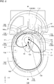
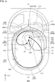
- Fig. 2 is a top view of the flush toilet 100.
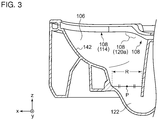
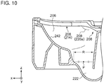
- Fig. 3 is a sectional side view of the toilet bowl 106.
- Fig. 4 is a sectional front view of the toilet bowl 106.
- Fig. 5 is a schematic diagram that shows flows of water toward a storage region 122.
- the water conveyance shelf 108 is an annular shelf formed along the entire periphery of the inner wall surface of the toilet bowl 106.
- the first shelf part 114 and the second shelf part 116 are smoothly connected by the shelf inclined surface 120a and a shelf inclined surface 120b.
- Each of the shelf inclined surfaces 120a and 120b is located within the rear half of the inner peripheral surface of the toilet bowl 106 in plan view (in the negative direction of the z-axis in Fig. 2 ).
- the shelf inclined surface 120a is an inclined surface on which the second flush water flows upward
- the shelf inclined surface 120b is an inclined surface on which the first flush water flows downward.
- the shelf inclined surfaces 120a and 120b are positioned symmetrically with respect to a central axis M (in an x-axis direction in Fig. 2 ) of the toilet bowl 106.
- Each of the first shelf part 114 and the second shelf part 116 may be a shelf extending in a horizontal direction, or the first shelf part 114 may be gently inclined upward around the front end part thereof, as shown in Fig. 3 .
- the shelf inclined surfaces 120a and 120b are formed to be steeper than the inclination in the first shelf part 114.
- the first shelf part 114 extends horizontally.
- the water conveyance shelf 108 is an annular shelf formed symmetrically with respect to the central axis M and having a height difference, in which the first shelf part 114 and the second shelf part 116 are smoothly connected by the shelf inclined surfaces 120a and 120b.
- the overhang 118 is formed along the entire periphery of the rim in the toilet bowl 106.
- the overhang 118 includes a first overhang 130 formed at a higher position corresponding to the first upper surface 110, and a second overhang 132 formed at a lower position corresponding to the second upper surface 112.
- the first overhang 130 and the second overhang 132 are smoothly connected by inclined surface overhangs 134a and 134b.
- the inclined surface overhang 134a corresponds to the upper inclined surface 140a and the shelf inclined surface 120a
- the inclined surface overhang 134b corresponds to the upper inclined surface 140b and the shelf inclined surface 120b.
- each of the inclined surface overhangs 134a and 134b is also located within the rear half of the inner peripheral surface of the toilet bowl 106 in plan view (in the negative direction of the z-axis in Fig. 2 ).
- the inclined surface overhangs 134a and 134b are positioned symmetrically with respect to the central axis M (in an x-axis direction in Fig. 2 ) of the toilet bowl 106.
- the overhang 118 is an annular overhang (a rim folded part) formed symmetrically with respect to the central axis M and having a height difference, in which the first overhang 130 and the second overhang 132 are smoothly connected by the inclined surface overhangs 134a and 134b.
- each of the overhang 118 and the water conveyance shelf 108 of the first embodiment is formed symmetrically with respect to the central axis M, the flush toilet 100 is designed so that the overall harmony can be easily maintained.
- the second discharge port 104 is formed on the shelf inclined surface 120b side, on the right side in the rear end part of the second shelf part 116.
- the first discharge port 102 is formed above the first shelf part 114.
- a third discharge port 124 is further formed on a side surface of the storage region 122.
- the first discharge port 102 is formed on an upper part (rim) of the left side surface (the negative direction side of the y-axis) of the flush toilet 100 viewed from the front.
- the first flush water S1 discharged through the first discharge port 102 largely swirls in the counterclockwise direction upon the water conveyance shelf 108 (first shelf part 114) to widely flush the front surface and the both side surfaces of the inner wall surface of the toilet bowl 106. While swirling upon the first shelf part 114, the first flush water S1 loses kinetic energy before reaching the shelf inclined surface 120b, so as to deviate from the course and flow down into the storage region 122 (see S1 in Fig. 2 ).
- the second flush water S2 discharged through the second discharge port 104 flows through the water conveyance shelf 108 (second shelf part 116) to locally flush an upper part of the rear end surface of the toilet bowl 106, and then deviates from the course because of the upward inclination (height difference) of the shelf inclined surface 120a, so as to flow down into the storage region 122 (see S2 in Fig. 2 ).
- the shelf inclined surface 120a is positioned in a rear and side part with respect to an opening R (see Fig. 3 ) of the storage region 122. More specifically, when the midpoint in an x direction (a longitudinal direction) of the opening R is defined as P, the shelf inclined surface 120a is formed at a position on the rear end side and the left side with respect to the midpoint P in plan view. Accordingly, after flowing up along the shelf inclined surface 120a, the second flush water S2 flows along a side of a receiving surface 142 and then directly flows down into the storage region 122 (see also Fig. 2 ). As shown in Fig. 3 , most of the second shelf part 116 and the first shelf part 114 are formed in a horizontal direction.
- the first shelf part 114 is formed at a position higher than the second upper surface 112 of the recess part 138 (see Fig. 4 ).
- Part of the second flush water S2 may be merged into the first flush water S1 without flowing down, but it may be desirable that the main flow of the second flush water S2 flows down without being merged into the first flush water S1.
- the "main flow” means 60 percent or above, preferably 80 percent or above and more preferably 95 percent or above, of the total amount of the second flush water S2 discharged through the second discharge port 104.
- the proportion of water flowing down without being merged into the first flush water S1 can be obtained by simulation calculation based on the position and size of the second discharge port 104, the flow rate of the second flush water S2, the shape and climbing angle of the shelf inclined surface 120a, and other various parameters.
- the first flush water S1 swirls along the inner wall of the toilet bowl 106 and then flows down from the right side, thereby widely providing the flushing force and water discharge force.
- the second flush water S2 flushes the rear end surface of the toilet bowl 106, which is particularly likely to get dirty, and then flows down from the rear left side, thereby locally providing the flushing force and water discharge force to the rear end surface.
- the third flush water S3 stirs the storage region 122 and pushes the waste out through the outlet 128, thereby providing the draining force.
- waste 126 is gathered in the storage region 122.
- waste that floats on the pooled water such as waste 126a-126c
- waste that sinks such as waste 126d.
- Each of the first flush water S1 and the second flush water S2 flows down into the storage region 122 from a different direction and sinks the waste 126a-126c into the storage region 122.
- the third flush water S3 pushes the waste 126a-126d thus gathered in the bottom part of the storage region 122 out through the outlet 128.
- the force of sinking the waste 126 into the storage region 122 will be referred to as the "sinking force".
- the sinking force of the first flush water S1 is applied to the waste 126a and 126b, but, since the waste 126c is not present immediately below the flow of the first flush water S1, the waste 126c is less likely to receive the sinking force of the first flush water S1. However, since the waste 126c is present immediately below the flow of the second flush water S2, the waste 126c receives the sinking force of the second flush water S2. In the first embodiment, since the first flush water S1 and the second flush water S2 flows down from the left and right directions, the sinking force can be effectively provided to floating waste 126.
- the second flush water S2 may be made to flow down by allowing the second flush water S2 that has flowed up along the shelf inclined surface 120a to hit on the back surface of the overhang 118 (which will be detailed in association with Fig. 6 ).
- the overhang 118 may be desirably formed to largely extend at a point where the second flush water S2 flowing up along the shelf inclined surface 120a enters the first shelf part 114. Since the second flush water S2 that does not flow down will be merged into the first flush water S1, the second flush water S2 can be efficiently and entirely used.
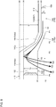
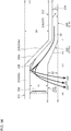
- Fig. 6 is a diagram that schematically shows a height relationship between the first shelf part 114 and the second shelf part 116 in the first embodiment.
- Fig. 7 is a diagram that schematically shows a height relationship between the first shelf part 114 and the second shelf part 116 in a comparative example.
- Fig. 6 The difference between Fig. 6 and Fig. 7 is whether or not the shelf inclined surface 120a is parallel with the overhang 118 near the second shelf part 116.
- the height of the second shelf part 116 is defined as H2, and the height of the first shelf part 114 is defined as H1.
- the height of the back surface of the second overhang 132 corresponding to the second upper surface 112 is defined as H3, and the height of the back surface of the first overhang 130 corresponding to the first upper surface 110 is defined as H4.
- the height of the second upper surface 112 (upper surface of the second overhang 132) is defined as H5
- the height of the first upper surface 110 (upper surface of the first overhang 130) is defined as H6.
- the boundary point between the second shelf part 116 and the shelf inclined surface 120a is defined as P1
- the boundary point between the shelf inclined surface 120a and the first shelf part 114 is defined as P3
- the middle point between P1 and P3 is defined as P2.
- the position of the first discharge port 102 is defined as P4.
- the second flush water S2 discharged through the second discharge port 104 flows through the second shelf part 116 and flows up along the shelf inclined surface 120a, losing kinetic energy, so as to flow down toward the storage region 122 while swirling.
- the second flush water S2 may be made to hit on the back surface of the first overhang 130 and rebound therefrom in the direction toward the storage region 122. Accordingly, it is desirable that a sufficient size of the overhang 118 is formed at least at the point where the second flush water S2 flowing up along the shelf inclined surface 120a enters the first shelf part 114. More specifically, it is desirable that the first overhang 130 is formed at least in the section between P3 and P4.
- the shelf inclined surface 120a and the inclined surface overhang 134a are at least partially parallel with each other in the water flowing direction. More specifically, at least in the section between P1 and P2, the shelf inclined surface 120a and the back surface of the overhang 118 (inclined surface overhang 134a) positioned thereabove are substantially parallel with each other.
- the “substantially parallel” means that the difference between the climbing angle of the shelf inclined surface 120a and the climbing angle of the inclined surface overhang 134a is 5 percent or less, preferably 1 percent or less.
- the “substantially parallel” in the present specification means that the difference in surface angle between the two surfaces is 5 percent or less, preferably 1 percent or less. As shown in the comparative example of Fig.
- the shelf inclined surface 120a is substantially parallel with not only the inclined surface overhang 134a but also the upper inclined surface 140a in the water flowing direction.
- the shelf inclined surface 120a is smoothly connected to the second shelf part 116, the second flush water can be smoothly led to the shelf inclined surface 120a while the force of the flush water can be maintained.
- the shelf inclined surface 120a needs to have a certain degree of gradient.
- the shelf inclined surface 120a may desirably include a gradient surface of 10 degrees or greater, preferably 35 degrees or greater.
- the shelf inclined surface 120a and the inclined surface overhang 134a are substantially parallel with each other in the inclination direction.
- the second shelf part 116 and the second overhang 132 are substantially parallel with each other in a horizontal direction
- the first shelf part 114 and the first overhang 130 are also substantially parallel with each other in a horizontal direction.
- the shelf inclined surface 120b and the inclined surface overhang 134b are annularly formed along the entire periphery of the toilet bowl 106, it is desirable that 80 percent or more, preferably 90 percent or more, of the entire periphery of the water conveyance shelf 108 is substantially parallel with the overhang 118.
- the water conveyance shelf 108 it is desirable that 80 percent or more, preferably 90 percent or more, of the entire periphery of the water conveyance shelf 108 is substantially parallel with the upper surface (the first upper surface 110, second upper surface 112, upper inclined surface 140a, and upper inclined surface 140b).
- the water conveyance shelf 108 so that the overhang 118 and the water conveyance shelf 108, or the upper surface and the water conveyance shelf 108, are substantially parallel with each other, the overall harmony in the design of the flush toilet 100 can be improved.
- the height difference D2 in the water conveyance shelf 108 is slightly moderated.
- the second shelf part 116 may be formed at a position lower than H2 in Fig. 6 . In this case, however, the potential energy of the second flush water will be smaller. Also, when the water passage in the second shelf part 116 is narrower, the pressure of the second flush water can be increased, and hence, the rear end surface can be strongly flushed.
- the first shelf part 114 may be formed at a position higher than H1 in Fig. 6 .
- the opening of the first discharge port 102 will also be smaller, and hence, the amount of water discharged through the first discharge port 102 will be reduced. Since the first flush water S1 needs to be sufficiently provided to the long first shelf part 114, and, particularly, a sufficient amount of water needs to be provided to the front end part of the toilet bowl 106, adding structural restriction on the amount of water discharged through the first discharge port 102 is unfavorable.
- the height difference D2 is provided between the first shelf part 114 and the second shelf part 116 so as to be commensurate with the height difference D1 between the first upper surface 110 and the second upper surface 112, and the water conveyance shelf 108 is formed so that T2 is smaller than T1 (T2 ⁇ T1, D2 ⁇ D1).
- the height T2 of the water passage in the second shelf part 116 is smaller than the height T1 of the water passage in the first shelf part 114. It is desirable that at least an average of the height of the water passage in the second shelf part 116 is smaller than an average of the height of the water passage in the first shelf part 114.
- the vertical width of the water passage is increased from T2 to T1.
- the vertical width of the water passage is maintained at T2 in the section between P1 and P2, and is then increased from T2 to T1 in the section between P2 and P3.
- the vertical width of the water passage has only to be increased at least within the section between P1 and P4. However, it is more suitable to maintain the vertical width of the water passage at T2 also in the section between P1 and P2 because the dead region 136 (unflushed region) is less likely to be formed, as described previously.
- the rear end surface of the toilet bowl 106 is particularly likely to get dirty. It will be desirable if such a region likely to get dirty can be flushed with flush water at a higher flow rate. Since the section between P2 and P3 is less likely to get dirty compared to the section between P1 and P2, it is suitable to increase the vertical width of the water passage in the section between P2 and P3 rather than in the section between P1 and P2.
- the second flush water S2 discharged through the second discharge port 104 flows up along the shelf inclined surface 120a and passes P2, and then diffuses in a vertical direction in the section between P2 and P3. Part of the flush water flows down therefrom, and another part of the flush water hits on the back surface of the first overhang 130 and flows down therefrom.
- the overhang 118 forms a water passage and prevents scattering of waste or flush water toward the first upper surface 110 and the second upper surface 112.
- the second overhang 132 prevents scattering of waste or flush water toward a functional unit mounted on the second upper surface 112. Upward scattering of waste that has scattered toward the rear end surface can be prevented by the back surface of the second overhang 132, which is flushed with the second flush water S2 afterward.
- the flowing path of the second flush water S2 is changed (deviated from the course) to the flowing down direction by means of the inclination in a longitudinal direction of the shelf inclined surface 120a.
- the restriction on the design of the water conveyance shelf 108 due to the recess part can be even utilized positively.
- the flow rate of the flush water can be increased or reduced, or the flow of flush water can be positively deviated from the course on the water conveyance shelf 108.
- the first flush water S1 swirls upon the first shelf part 114 retaining the potential energy.
- the first flush water S1 then deviates from the course before the shelf inclined surface 120b and flows down into the storage region 122.
- the second flush water S2 flows through a narrow water passage on the second shelf part 116 at a high flow rate to flush the rear end surface, and then flows up along the shelf inclined surface 120a and deviates from the course. Also, part of the second flush water S2 splashing from the shelf inclined surface 120a strongly rebounds from the overhang 118 toward the storage region 122.
- the flow of the second flush water S2 is deviated from the course to the flowing down direction by means of the height difference in the shelf inclined surface 120a. After flowing through the shelf inclined surface 120b, part of the first flush water S1 may be merged into the second flush water S2.
- the second flush water S2 will slow down if the first flush water S1, which has flowed around in the toilet bowl 106 and has slowed down, is merged into the second flush water S2, it is desirable that the proportion of the first flush water S1 to be merged into the second flush water S2 after flowing around is a small amount less than 20 percent, preferably less than 10 percent.
- a stepped surface including the first upper surface 110 and the second upper surface 112 is provided to form a recess part, on which a functional unit is mounted, in the rear end part of the flush toilet 100.
- the present invention is also applicable to designing when the water conveyance shelf 108 is formed so as to correspond to a step on the upper surface, which is not limited to a recess part.
- the width of the water conveyance shelf 108 need not necessarily be constant and may be changed depending on a place.
- the water conveyance shelf 108 need not necessarily be horizontal and may be inclined or curved with respect to a horizontal plane.
- the water conveyance shelf 108 need not necessarily be continuously provided along the entire periphery of the toilet bowl 106 and may partially include a discontinuous region (such as a cutout).
- each of the back surface of the overhang 118 and the upper surface of the water conveyance shelf 108 forms a horizontal surface. Accordingly, the cross section of the water passage between the overhang 118 and the water conveyance shelf 108 is rectangular (see the region U in Fig. 4 ). As a modification, the overhang 118 and the water conveyance shelf 108 may be smoothly connected, so that the cross section of the water passage includes an arc. In the present invention, the overhang 118 is an optional component and is not an essential component.
- a flush toilet includes: a body part with a toilet bowl part formed therein, including a first upper surface positioned higher and a second upper surface positioned lower; a water conveyance shelf formed along a circumferential direction of the toilet bowl part on an inner wall surface of the toilet bowl part; and a discharge port formed so that water is discharged therethrough to the water conveyance shelf.
- the water conveyance shelf includes a first shelf part formed at a corresponding position of the first upper surface and also includes a second shelf part formed at a corresponding position of the second upper surface.
- the second shelf part is positioned lower than the first shelf part.
- a height difference is provided in the water conveyance shelf so as to be commensurate with the height difference in the upper surface, and, by means of the height difference in the water conveyance shelf, the flow of water can be controlled.
- the second shelf part may be smoothly connected with the first shelf part by a shelf inclined surface.
- the first upper surface and the second upper surface may be smoothly connected by an upper inclined surface.
- the shelf inclined surface may be an inclined surface substantially parallel with the upper inclined surface at least in a section between the boundary point between the second shelf part and the shelf inclined surface and the center point in the shelf inclined surface.
- the shelf inclined surface may be an inclined surface substantially parallel with the overhang part at least in a section between the boundary point between the second shelf part and the shelf inclined surface and the center point in the shelf inclined surface.
- the toilet bowl part may include a first discharge port and a second discharge port formed therein.
- the first discharge port may be formed so that water is discharged therethrough to the first shelf part, and the second discharge port may be formed so that water is discharged therethrough to the second shelf part.
- the overall harmony in design can be maintained more easily.
- the water conveyance shelf may be annularly formed along the entire periphery of the toilet bowl part, and at least 80 percent of the entire periphery of the water conveyance shelf may be substantially parallel with the overhang part.
- An average of the interval between the first shelf part and the first upper surface may be greater than an average of the interval between the second shelf part and the second upper surface.
- the interval between the water conveyance shelf and an upper surface part may be increased toward the first discharge port.
- a recess part may be formed in a rear end part of the upper surface of the toilet bowl part.
- the second upper surface may correspond to the bottom surface of the recess part.
- a flush toilet includes: a body part with a toilet bowl part formed therein; a water conveyance shelf formed along a circumferential direction on an inner wall surface of the toilet bowl part and including a first shelf part positioned higher and a second shelf part positioned lower; a first discharge port formed so that water is discharged therethrough to the first shelf part; and a second discharge port positioned lower than the first discharge port and formed so that water is discharged therethrough to the second shelf part.
- the first shelf part and the second shelf part may be smoothly connected by a shelf inclined surface.
- an overhang part may be formed on the upper surface of the toilet bowl part.
- a storage region may be formed to pool flush water.
- the main flow of water discharged through the second discharge port may be made to flow down into the storage region without being merged into water discharged through the first discharge port in the first shelf part.
- the draining force can be increased more easily.
- the amount of water discharged through the second discharge port and flowing up along the shelf inclined surface to be merged into water discharged through the first discharge port may be less than 20 percent of the total amount of the water discharged through the second discharge port.
- the shelf inclined surface along which water discharged through the second discharge port flows up may include a gradient surface of 10 degrees or greater.
- the water conveyance shelf may be annularly formed along the entire periphery of the toilet bowl part, in which the first shelf part and the second shelf part are connected by two shelf inclined surfaces. Each of the two shelf inclined surfaces may be formed in the rear half of the toilet bowl part in plan view.
- the first shelf part may be longer than the second shelf part.
- a shelf inclined surface along which flush water that has flowed through the second shelf part flows up toward the first shelf part may be formed in a side part, in plan view, with respect to a storage region formed in a bottom part of the toilet bowl part.
- Fig. 8 is an external perspective view of a flush toilet 200.
- a toilet bowl 206 is formed in a body part 244 of the flush toilet 200. Also, in the body part 244, flush water stored in an external tank is discharged to the toilet bowl 206 through a first discharge port 202 and a second discharge port 204. Part of the flush water is also discharged through a third discharge port, which will be described later in association with Fig. 9 .
- the third discharge port may be a so-called jet discharge port.
- the first discharge port 202 is formed on a side surface (the negative direction side of the y-axis) of the toilet bowl 206.
- the second discharge port 204 is formed on a rear end surface (the negative direction side of the x-axis) of the toilet bowl 206.
- a water conveyance shelf 208 is annularly formed.
- the flush water discharged through the second discharge port 204 (hereinafter, referred to as “second flush water”) flows upon the water conveyance shelf 208, and most of the flush water flows down into the toilet bowl 206 before the first discharge port 202, while the remaining flush water is merged into the flush water discharged through the first discharge port 202 (hereinafter, referred to as "first flush water”).
- the first flush water swirls upon the water conveyance shelf 208, thereby flushing the entirety of the toilet bowl 206, particularly the front surface and the both side surfaces of the inner wall.
- the upper surface of the toilet bowl 206 is formed as a stepped surface including a first upper surface 210 positioned higher and a second upper surface 212 positioned lower.
- the second upper surface 212 in the second embodiment forms a flat bottom surface of a recess part 238 in the upper surface.
- the second upper surface 212 need not necessarily be flat, and it may be formed as a surface curved downward or upward, or a projection or a cutout may be formed in part of the second upper surface 212.
- a functional unit (not illustrated) for providing the pubic lavage function or the warm air function, for example, is mounted on the recess part 238 (upon the second upper surface 212).
- the second upper surface 212 and the first upper surface 210 are smoothly connected by two upper inclined surfaces 240a and 240b, so that an annular upper surface having a height difference is formed.
- the water conveyance shelf 208 includes a first shelf part 214 positioned higher and a second shelf part 216 positioned lower.
- the first shelf part 214 is formed at a corresponding position of the first upper surface 210
- the second shelf part 216 is formed at a corresponding position of the second upper surface 212.
- the "corresponding position” means a position corresponding, in a vertical direction (z-axis direction), to another position and, in other words, it means a position that overlaps another position in plan view.
- first shelf part 214 (higher shelf) is formed so as to correspond to 90 percent or more of the inner peripheral line of the first upper surface 210 (higher surface), and the second shelf part 216 (lower shelf) is formed so as to correspond to 90 percent or more of the inner peripheral line of the second upper surface 212 (lower surface) (see also Fig. 9 ).
- first shelf part 214 is longer than the second shelf part 216.
- a height difference is provided between the first shelf part 214 and the second shelf part 216 in the water conveyance shelf 208 so as to be commensurate with the height difference (step) between the first upper surface 210 and the second upper surface 212 in the upper surface part.
- the first shelf part 214 and the second shelf part 216 are connected by a smooth inclined surface (shelf inclined surface 220a) (which will be detailed in association with Fig. 9 ).
- Shelf inclined surface 220a which will be detailed in association with Fig. 9 ).
- Being “smooth" in the present specification means that surfaces are continuously connected with each other, or surfaces are connected with each other without including a discontinuous surface.
- the upper surface (the first upper surface 210, second upper surface 212, and upper inclined surfaces 240a and 240b) extends inward, so as to form an overhang 218 (a rim folded part) over the entire periphery.
- the overhang 218 is, in a manner, a roof for the water conveyance shelf 208, and the water conveyance shelf 208 and the overhang 218 form a water passage.
- the overhang 218 of the second embodiment is annularly formed along the entire inner periphery of the toilet bowl 206.
- the water conveyance shelf 208 excluding part thereof, includes a surface substantially in parallel with the overhang 218 mainly in a horizontal direction (the water flowing direction). More specifically, the lower surface of the overhang 218 (the surface facing the water conveyance shelf 208) is substantially parallel with the upper surface of the water conveyance shelf 208 in the water flowing direction.
- Fig. 9 is a top view of the flush toilet 200.
- Fig. 10 is a sectional side view of the toilet bowl 206.
- Fig. 11 is a sectional front view of the toilet bowl 206.
- Fig. 12 is a schematic diagram that shows flows of water toward a storage region 222.
- the water conveyance shelf 208 is an annular shelf formed along the entire periphery of the inner wall surface of the toilet bowl 206.
- the first shelf part 214 and the second shelf part 216 are smoothly connected by the shelf inclined surface 220a and a shelf inclined surface 220b.
- Each of the shelf inclined surfaces 220a and 220b is located within the rear half of the inner peripheral surface of the toilet bowl 206 in plan view (in the negative direction of the z-axis in Fig. 9 ).
- the shelf inclined surface 220a is an inclined surface on which the second flush water flows upward
- the shelf inclined surface 220b is an inclined surface on which the first flush water flows downward.
- the shelf inclined surfaces 220a and 220b are positioned symmetrically with respect to a central axis M (in an x-axis direction in Fig. 9 ) of the toilet bowl 206.
- Each of the first shelf part 214 and the second shelf part 216 may be a shelf extending in a horizontal direction, or the first shelf part 214 may be gently inclined upward around the front end part thereof, as shown in Fig. 10 .
- the shelf inclined surfaces 220a and 220b are formed to be steeper than the inclination in the first shelf part 214.
- the first shelf part 214 extends horizontally.
- the water conveyance shelf 208 is an annular shelf formed symmetrically with respect to the central axis M and having a height difference, in which the first shelf part 214 and the second shelf part 216 are smoothly connected by the shelf inclined surfaces 220a and 220b.
- the overhang 218 is formed along the entire periphery of the rim in the toilet bowl 206.
- the overhang 218 includes a first overhang 230 formed at a higher position corresponding to the first upper surface 210, and a second overhang 232 formed at a lower position corresponding to the second upper surface 212.
- the first overhang 230 and the second overhang 232 are smoothly connected by inclined surface overhangs 234a and 234b.
- the inclined surface overhang 234a corresponds to the upper inclined surface 240a and the shelf inclined surface 220a
- the inclined surface overhang 234b corresponds to the upper inclined surface 240b and the shelf inclined surface 220b.
- each of the inclined surface overhangs 234a and 234b is also located within the rear half of the inner peripheral surface of the toilet bowl 206 in plan view (in the negative direction of the z-axis in Fig. 9 ).
- the inclined surface overhangs 234a and 234b are positioned symmetrically with respect to the central axis M (in an x-axis direction in Fig. 9 ) of the toilet bowl 206.
- the overhang 218 is an annular overhang (a rim folded part) formed symmetrically with respect to the central axis M and having a height difference, in which the first overhang 230 and the second overhang 232 are smoothly connected by the inclined surface overhangs 234a and 234b.
- each of the overhang 218 and the water conveyance shelf 208 of the second embodiment is formed symmetrically with respect to the central axis M, the flush toilet 200 is designed so that the overall harmony can be easily maintained.
- the second discharge port 204 is formed on the shelf inclined surface 220b side, on the right side in the rear end part of the second shelf part 216.
- the first discharge port 202 is formed above the first shelf part 214.
- a third discharge port 224 is further formed on a side surface of the storage region 222.
- the first discharge port 202 is formed on an upper part (rim) of the left side surface (the negative direction side of the y-axis) of the flush toilet 200 viewed from the front.
- the first flush water S1 discharged through the first discharge port 202 largely swirls in the counterclockwise direction upon the water conveyance shelf 208 (first shelf part 214) to widely flush the front surface and the both side surfaces of the inner wall surface of the toilet bowl 206. While swirling upon the first shelf part 214, the first flush water S1 loses kinetic energy before reaching the shelf inclined surface 220b, so as to deviate from the course and flow down into the storage region 222 (see S1 in Fig. 9 ).
- the second flush water S2 discharged through the second discharge port 204 flows through the water conveyance shelf 208 (second shelf part 216) to locally flush an upper part of the rear end surface of the toilet bowl 206, and then deviates from the course because of the upward inclination (height difference) of the shelf inclined surface 220a, so as to flow down into the storage region 222 (see S2 in Fig. 9 ).
- the shelf inclined surface 220a is positioned in a rear and side part with respect to an opening R (see Fig. 10 ) of the storage region 222. More specifically, when the midpoint in an x direction (a longitudinal direction) of the opening R is defined as P, the shelf inclined surface 220a is formed at a position on the rear end side and the left side with respect to the midpoint P in plan view. Accordingly, after flowing up along the shelf inclined surface 220a, the second flush water S2 flows along a side of a receiving surface 242 and then directly flows down into the storage region 222 (see also Fig. 9 ). As shown in Fig. 10 , most of the second shelf part 216 and the first shelf part 214 are formed in a horizontal direction.
- the first shelf part 214 is formed at a position higher than the second upper surface 212 of the recess part 238 (see Fig. 11 ).
- Part of the second flush water S2 may be merged into the first flush water S1 without flowing down, but it may be desirable that the main flow of the second flush water S2 flows down without being merged into the first flush water S1.
- the "main flow” means 60 percent or above, preferably 80 percent or above and more preferably 95 percent or above, of the total amount of the second flush water S2 discharged through the second discharge port 204.
- the proportion of water flowing down without being merged into the first flush water S1 can be obtained by simulation calculation based on the position and size of the second discharge port 204, the flow rate of the second flush water S2, the shape and climbing angle of the shelf inclined surface 220a, and other various parameters.
- the first flush water S1 swirls along the inner wall of the toilet bowl 206 and then flows down from the right side, thereby widely providing the flushing force and water discharge force.
- the second flush water S2 flushes the rear end surface of the toilet bowl 206, which is particularly likely to get dirty, and then flows down from the rear left side, thereby locally providing the flushing force and water discharge force to the rear end surface.
- the third flush water S3 stirs the storage region 222 and pushes the waste out through the outlet 228, thereby providing the draining force.
- waste 226 is gathered in the storage region 222.
- waste that floats on the pooled water such as waste 226a-226c
- waste that sinks such as waste 226d.
- Each of the first flush water S1 and the second flush water S2 flows down into the storage region 222 from a different direction and sinks the waste 226a-226c into the storage region 222.
- the third flush water S3 pushes the waste 226a-226d thus gathered in the bottom part of the storage region 222 out through the outlet 228.
- the force of sinking the waste 226 into the storage region 222 will be referred to as the "sinking force".
- the sinking force of the first flush water S1 is applied to the waste 226a and 226b, but, since the waste 226c is not present immediately below the flow of the first flush water S1, the waste 226c is less likely to receive the sinking force of the first flush water S1. However, since the waste 226c is present immediately below the flow of the second flush water S2, the waste 226c receives the sinking force of the second flush water S2. In the second embodiment, since the first flush water S1 and the second flush water S2 flows down from the left and right directions, the sinking force can be effectively provided to floating waste 226.
- the second flush water S2 may be made to flow down by allowing the second flush water S2 that has flowed up along the shelf inclined surface 220a to hit on the back surface of the overhang 218 (which will be detailed in association with Fig. 13 ).
- the overhang 218 may be desirably formed to largely extend at a point where the second flush water S2 flowing up along the shelf inclined surface 220a enters the first shelf part 214. Since the second flush water S2 that does not flow down will be merged into the first flush water S1, the second flush water S2 can be efficiently and entirely used.
- Fig. 13 is a diagram that schematically shows a height relationship between the first shelf part 214 and the second shelf part 216 in the second embodiment.
- Fig. 14 is a diagram that schematically shows a height relationship between the first shelf part 214 and the second shelf part 216 in a comparative example.
- Fig. 13 The difference between Fig. 13 and Fig. 14 is whether or not the shelf inclined surface 220a is parallel with the overhang 218 near the second shelf part 216.
- the height of the second shelf part 216 is defined as H2, and the height of the first shelf part 214 is defined as H1.
- the height of the back surface of the second overhang 232 corresponding to the second upper surface 212 is defined as H3
- the height of the back surface of the first overhang 230 corresponding to the first upper surface 210 is defined as H4.
- the height of the second upper surface 212 (upper surface of the second overhang 232) is defined as H5
- the height of the first upper surface 210 is defined as H6.
- the boundary point between the second shelf part 216 and the shelf inclined surface 220a is defined as P1
- the boundary point between the shelf inclined surface 220a and the first shelf part 214 is defined as P3
- the middle point between P1 and P3 is defined as P2.
- the position of the first discharge port 202 is defined as P4.
- the second flush water S2 discharged through the second discharge port 204 flows through the second shelf part 216 and flows up along the shelf inclined surface 220a, losing kinetic energy, so as to flow down toward the storage region 222 while swirling.
- the second flush water S2 may be made to hit on the back surface of the first overhang 230 and rebound therefrom in the direction toward the storage region 222. Accordingly, it is desirable that a sufficient size of the overhang 218 is formed at least at the point where the second flush water S2 flowing up along the shelf inclined surface 220a enters the first shelf part 214. More specifically, it is desirable that the first overhang 230 is formed at least in the section between P3 and P4.
- the shelf inclined surface 220a and the inclined surface overhang 234a are at least partially parallel with each other in the water flowing direction. More specifically, at least in the section between P1 and P2, the shelf inclined surface 220a and the back surface of the overhang 218 (inclined surface overhang 234a) positioned thereabove are substantially parallel with each other.
- the “substantially parallel” means that the difference between the climbing angle of the shelf inclined surface 220a and the climbing angle of the inclined surface overhang 234a is 5 percent or less, preferably 1 percent or less.
- the “substantially parallel” in the present specification means that the difference in surface angle between the two surfaces is 5 percent or less, preferably 1 percent or less. As shown in the comparative example of Fig.
- a dead region 236 (an unflushed region) is formed below the inclined surface overhang 234a, and it may be unable to flush the region sufficiently.
- the experiments performed by the inventors and others have found that, in the configuration as shown in the comparative example of Fig. 14 , when the second flush water S2 passes P1 and is then diffused in a vertical direction, a sufficient amount of the second flush water S2 is less likely to reach the back surface of the overhang 218 around P3.
- the shelf inclined surface 220a and the inclined surface overhang 234a to be substantially parallel with each other in the section between P1 and P2, as shown in Fig. 13 , the formation of the dead region 236 can be prevented.
- the shelf inclined surface 220a is substantially parallel with not only the inclined surface overhang 234a but also the upper inclined surface 240a in the water flowing direction.
- the shelf inclined surface 220a is smoothly connected to the second shelf part 216, the second flush water can be smoothly led to the shelf inclined surface 220a while the force of the flush water can be maintained.
- the shelf inclined surface 220a needs to have a certain degree of gradient.
- the shelf inclined surface 220a may desirably include a gradient surface of 10 degrees or greater, preferably 35 degrees or greater.
- the shelf inclined surface 220a and the inclined surface overhang 234a are substantially parallel with each other in the inclination direction.
- the second shelf part 216 and the second overhang 232 are substantially parallel with each other in a horizontal direction
- the first shelf part 214 and the first overhang 230 are also substantially parallel with each other in a horizontal direction.
- the shelf inclined surface 220b and the inclined surface overhang 234b are annularly formed along the entire periphery of the toilet bowl 206, it is desirable that 80 percent or more, preferably 90 percent or more, of the entire periphery of the water conveyance shelf 208 is substantially parallel with the overhang 218.
- the water conveyance shelf 208 it is desirable that 80 percent or more, preferably 90 percent or more, of the entire periphery of the water conveyance shelf 208 is substantially parallel with the upper surface (the first upper surface 210, second upper surface 212, upper inclined surface 240a, and upper inclined surface 240b).
- the water conveyance shelf 208 By configuring the water conveyance shelf 208 so that the overhang 218 and the water conveyance shelf 208, or the upper surface and the water conveyance shelf 208, are substantially parallel with each other, the overall harmony in the design of the flush toilet 200 can be improved.
- the height difference D2 in the water conveyance shelf 208 is slightly moderated.
- the second shelf part 216 may be formed at a position lower than H2 in Fig. 13 . In this case, however, the potential energy of the second flush water will be smaller. Also, when the water passage in the second shelf part 216 is narrower, the pressure of the second flush water can be increased, and hence, the rear end surface can be strongly flushed.
- the first shelf part 214 may be formed at a position higher than H1 in Fig. 13 .
- the opening of the first discharge port 202 will also be smaller, and hence, the amount of water discharged through the first discharge port 202 will be reduced. Since the first flush water S1 needs to be sufficiently provided to the long first shelf part 214, and, particularly, a sufficient amount of water needs to be provided to the front end part of the toilet bowl 206, adding structural restriction on the amount of water discharged through the first discharge port 202 is unfavorable.
- the height difference D2 is provided between the first shelf part 214 and the second shelf part 216 so as to be commensurate with the height difference D1 between the first upper surface 210 and the second upper surface 212, and the water conveyance shelf 208 is formed so that T2 is smaller than T1 (T2 ⁇ T1, D2 ⁇ D1).
- the height T2 of the water passage in the second shelf part 216 is smaller than the height T1 of the water passage in the first shelf part 214. It is desirable that at least an average of the height of the water passage in the second shelf part 216 is smaller than an average of the height of the water passage in the first shelf part 214.
- the vertical width of the water passage is increased from T2 to T1.
- the vertical width of the water passage is maintained at T2 in the section between P1 and P2, and is then increased from T2 to T1 in the section between P2 and P3.
- the vertical width of the water passage has only to be increased at least within the section between P1 and P4. However, it is more suitable to maintain the vertical width of the water passage at T2 also in the section between P1 and P2 because the dead region 236 (unflushed region) is less likely to be formed, as described previously.
- the rear end surface of the toilet bowl 206 is particularly likely to get dirty. It will be desirable if such a region likely to get dirty can be flushed with flush water at a higher flow rate. Since the section between P2 and P3 is less likely to get dirty compared to the section between P1 and P2, it is suitable to increase the vertical width of the water passage in the section between P2 and P3 rather than in the section between P1 and P2.
- the second flush water S2 discharged through the second discharge port 204 flows up along the shelf inclined surface 220a and passes P2, and then diffuses in a vertical direction in the section between P2 and P3. Part of the flush water flows down therefrom, and another part of the flush water hits on the back surface of the first overhang 230 and flows down therefrom.
- the overhang 218 forms a water passage and prevents scattering of waste or flush water toward the first upper surface 210 and the second upper surface 212.
- the second overhang 232 prevents scattering of waste or flush water toward a functional unit mounted on the second upper surface 212. Upward scattering of waste that has scattered toward the rear end surface can be prevented by the back surface of the second overhang 232, which is flushed with the second flush water S2 afterward.
- the flowing path of the second flush water S2 is changed (deviated from the course) to the flowing down direction by means of the inclination in a longitudinal direction of the shelf inclined surface 220a.
- the restriction on the design of the water conveyance shelf 208 due to the recess part can be even utilized positively.
- the flow rate of the flush water can be increased or reduced, or the flow of flush water can be positively deviated from the course on the water conveyance shelf 208.
- the first flush water S1 swirls upon the first shelf part 214 retaining the potential energy.
- the first flush water S1 then deviates from the course before the shelf inclined surface 220b and flows down into the storage region 222.
- the second flush water S2 flows through a narrow water passage on the second shelf part 216 at a high flow rate to flush the rear end surface, and then flows up along the shelf inclined surface 220a and deviates from the course. Also, part of the second flush water S2 splashing from the shelf inclined surface 220a strongly rebounds from the overhang 218 toward the storage region 222.
- the flow of the second flush water S2 is deviated from the course to the flowing down direction by means of the height difference in the shelf inclined surface 220a.
- part of the first flush water S1 may be merged into the second flush water S2.
- the second flush water S2 will slow down if the first flush water S1, which has flowed around in the toilet bowl 206 and has slowed down, is merged into the second flush water S2, it is desirable that the proportion of the first flush water S1 to be merged into the second flush water S2 after flowing around is a small amount less than 20 percent, preferably less than 10 percent.
- a stepped surface including the first upper surface 210 and the second upper surface 212 is provided to form a recess part, on which a functional unit is mounted, in the rear end part of the flush toilet 200.
- the present invention is also applicable to designing when the water conveyance shelf 208 is formed so as to correspond to a step on the upper surface, which is not limited to a recess part.
- the width of the water conveyance shelf 208 need not necessarily be constant and may be changed depending on a place.
- the water conveyance shelf 208 need not necessarily be horizontal and may be inclined or curved with respect to a horizontal plane.
- the water conveyance shelf 208 need not necessarily be continuously provided along the entire periphery of the toilet bowl 206 and may partially include a discontinuous region (such as a cutout).
- a flush toilet includes: a body part with a toilet bowl part formed therein; a water conveyance shelf formed along a circumferential direction on an inner wall surface of the toilet bowl part and including a first shelf part positioned higher and a second shelf part positioned lower; a first discharge port formed so that water is discharged therethrough to the first shelf part; and a second discharge port positioned lower than the first discharge port and formed so that water is discharged therethrough to the second shelf part.
- the first shelf part and the second shelf part may be smoothly connected by a shelf inclined surface.
- an overhang part may be formed on the upper surface of the toilet bowl part.
- a storage region may be formed to pool flush water.
- the main flow of water discharged through the second discharge port may be made to flow down into the storage region without being merged into water discharged through the first discharge port in the first shelf part.
- the draining force can be increased more easily.
- the amount of water discharged through the second discharge port and flowing up along the shelf inclined surface to be merged into water discharged through the first discharge port may be less than 20 percent of the total amount of the water discharged through the second discharge port.
- the shelf inclined surface along which water discharged through the second discharge port flows up may include a gradient surface of 10 degrees or greater.
- the water conveyance shelf may be annularly formed along the entire periphery of the toilet bowl part, in which the first shelf part and the second shelf part are connected by two shelf inclined surfaces. Each of the two shelf inclined surfaces may be formed in the rear half of the toilet bowl part in plan view.
- the first shelf part may be longer than the second shelf part.
- the flush water from the second discharge port can be made to strongly flow upward while the kinetic energy of the flush water is maintained.
- the main flow of the flush water from the second discharge port flows down, and the flush water that does not flow down will be merged into the flush water from the first discharge port.
- a shelf inclined surface along which flush water that has flowed through the second shelf part flows up toward the first shelf part may be formed in a side part, in plan view, with respect to a storage region formed in a bottom part of the toilet bowl part.
- a flush toilet includes: a body part with a toilet bowl part formed therein, including a first upper surface positioned higher and a second upper surface positioned lower; a water conveyance shelf formed along a circumferential direction of the toilet bowl part on an inner wall surface of the toilet bowl part; and a discharge port formed so that water is discharged therethrough to the water conveyance shelf.
- the water conveyance shelf includes a first shelf part formed at a corresponding position of the first upper surface and also includes a second shelf part formed at a corresponding position of the second upper surface.
- the second shelf part is positioned lower than the first shelf part.
- a height difference is provided in the water conveyance shelf so as to be commensurate with the height difference in the upper surface, and, by means of the height difference in the water conveyance shelf, the flow of water can be controlled.
- the second shelf part may be smoothly connected with the first shelf part by a shelf inclined surface.
- the first upper surface and the second upper surface may be smoothly connected by an upper inclined surface.
- the shelf inclined surface may be an inclined surface substantially parallel with the upper inclined surface at least in a section between the boundary point between the second shelf part and the shelf inclined surface and the center point in the shelf inclined surface.
- the shelf inclined surface may be an inclined surface substantially parallel with the overhang part at least in a section between the boundary point between the second shelf part and the shelf inclined surface and the center point in the shelf inclined surface.
- the toilet bowl part may include a first discharge port and a second discharge port formed therein.
- the first discharge port may be formed so that water is discharged therethrough to the first shelf part, and the second discharge port may be formed so that water is discharged therethrough to the second shelf part.
- a first discharge port and a second discharge port may be formed on an upper end of the inner wall of the toilet bowl part.
- the first discharge port may be formed on the first shelf part
- the second discharge port may be formed on the second shelf part.
- the interval between the water conveyance shelf and an upper surface part may be increased toward the first discharge port.
- the overall harmony in design can be maintained more easily.
- a first discharge port and a second discharge port may be formed on an upper end of the inner wall of the toilet bowl part.
- the first discharge port may be formed on the first shelf part, and the second discharge port may be formed on the second shelf part.
- the water conveyance shelf may be annularly formed along the entire periphery of the toilet bowl part, and at least 80 percent of the entire periphery of the water conveyance shelf may be substantially parallel with the overhang part.
- An average of the interval between the first shelf part and the first upper surface may be greater than an average of the interval between the second shelf part and the second upper surface.
- the interval between the water conveyance shelf and an upper surface part may be increased toward the first discharge port.
- a recess part In a rear end part of the upper surface of the toilet bowl part, a recess part may be formed.
- the second upper surface may correspond to the bottom surface of the recess part.
- the present invention is applicable to a flush toilet.
Landscapes
- Health & Medical Sciences (AREA)
- Life Sciences & Earth Sciences (AREA)
- Engineering & Computer Science (AREA)
- Hydrology & Water Resources (AREA)
- Public Health (AREA)
- Water Supply & Treatment (AREA)
- Sanitary Device For Flush Toilet (AREA)
Applications Claiming Priority (3)
| Application Number | Priority Date | Filing Date | Title |
|---|---|---|---|
| JP2015172294A JP6411976B2 (ja) | 2015-09-01 | 2015-09-01 | 水洗式便器 |
| JP2015172295A JP6411977B2 (ja) | 2015-09-01 | 2015-09-01 | 水洗式便器 |
| PCT/JP2016/070690 WO2017038258A1 (fr) | 2015-09-01 | 2016-07-13 | Toilettes à chasse d'eau |
Publications (3)
| Publication Number | Publication Date |
|---|---|
| EP3346065A1 true EP3346065A1 (fr) | 2018-07-11 |
| EP3346065A4 EP3346065A4 (fr) | 2019-06-19 |
| EP3346065B1 EP3346065B1 (fr) | 2022-02-16 |
Family
ID=58187096
Family Applications (1)
| Application Number | Title | Priority Date | Filing Date |
|---|---|---|---|
| EP16841290.6A Not-in-force EP3346065B1 (fr) | 2015-09-01 | 2016-07-13 | Toilettes à chasse d'eau |
Country Status (3)
| Country | Link |
|---|---|
| EP (1) | EP3346065B1 (fr) |
| CN (1) | CN107923173B (fr) |
| WO (1) | WO2017038258A1 (fr) |
Families Citing this family (1)
| Publication number | Priority date | Publication date | Assignee | Title |
|---|---|---|---|---|
| JP7151685B2 (ja) * | 2019-09-30 | 2022-10-12 | Toto株式会社 | 水洗大便器 |
Family Cites Families (9)
| Publication number | Priority date | Publication date | Assignee | Title |
|---|---|---|---|---|
| EP2261428B1 (fr) * | 2008-02-29 | 2022-08-17 | Toto Ltd. | Dispositif de toilettes |
| JP5257846B2 (ja) * | 2009-02-25 | 2013-08-07 | Toto株式会社 | 水洗大便器 |
| EP2562314B1 (fr) * | 2011-08-24 | 2022-05-11 | Toto Ltd. | Chasse d'eau |
| CN102605840A (zh) * | 2012-03-12 | 2012-07-25 | 虞吉伟 | 坐圈封闭式全洗喷射坐便器 |
| JP6194570B2 (ja) * | 2012-09-24 | 2017-09-13 | Toto株式会社 | 水洗大便器 |
| JP6260766B2 (ja) * | 2013-09-30 | 2018-01-17 | Toto株式会社 | 水洗大便器装置 |
| JP6242140B2 (ja) * | 2013-10-04 | 2017-12-06 | 株式会社Lixil | 汚物排出装置 |
| JP6238011B2 (ja) * | 2014-05-28 | 2017-11-29 | Toto株式会社 | 水洗大便器 |
| JP6068417B2 (ja) * | 2014-10-27 | 2017-01-25 | 株式会社Lixil | 水洗式便器 |
-
2016
- 2016-07-13 WO PCT/JP2016/070690 patent/WO2017038258A1/fr not_active Ceased
- 2016-07-13 CN CN201680049178.2A patent/CN107923173B/zh not_active Expired - Fee Related
- 2016-07-13 EP EP16841290.6A patent/EP3346065B1/fr not_active Not-in-force
Also Published As
| Publication number | Publication date |
|---|---|
| EP3346065A4 (fr) | 2019-06-19 |
| WO2017038258A1 (fr) | 2017-03-09 |
| EP3346065B1 (fr) | 2022-02-16 |
| CN107923173B (zh) | 2020-02-21 |
| CN107923173A (zh) | 2018-04-17 |
Similar Documents
| Publication | Publication Date | Title |
|---|---|---|
| JP6573066B2 (ja) | 水洗大便器 | |
| JP2015190245A (ja) | 水洗大便器 | |
| JP2013019242A (ja) | 水洗大便器 | |
| CN107201776B (zh) | 冲水大便器 | |
| JP6238011B2 (ja) | 水洗大便器 | |
| JP6331212B2 (ja) | 水洗大便器 | |
| JP6411976B2 (ja) | 水洗式便器 | |
| CN107849841A (zh) | 抽水马桶 | |
| JP2017145631A (ja) | 水洗大便器 | |
| JP5930616B2 (ja) | 便器排水路 | |
| EP3346065B1 (fr) | Toilettes à chasse d'eau | |
| JP2022173376A (ja) | 水洗大便器 | |
| JP7118355B2 (ja) | 水洗大便器 | |
| JP5715403B2 (ja) | 水洗式便器の排水路 | |
| JP7082312B2 (ja) | 水洗大便器 | |
| JP5715404B2 (ja) | 水洗式便器の排水路 | |
| JP5223988B2 (ja) | 水洗大便器 | |
| JP2014088765A (ja) | 水洗大便器 | |
| JP5715402B2 (ja) | 水洗式便器の排水路 | |
| JP2019173324A (ja) | 水洗大便器 | |
| JP6079967B2 (ja) | 水洗大便器 | |
| JP2014058863A (ja) | 水洗大便器 | |
| JP6094939B2 (ja) | 水洗大便器 | |
| JP6102047B2 (ja) | 洗い落し式便器 | |
| JP6411977B2 (ja) | 水洗式便器 |
Legal Events
| Date | Code | Title | Description |
|---|---|---|---|
| STAA | Information on the status of an ep patent application or granted ep patent |
Free format text: STATUS: THE INTERNATIONAL PUBLICATION HAS BEEN MADE |
|
| PUAI | Public reference made under article 153(3) epc to a published international application that has entered the european phase |
Free format text: ORIGINAL CODE: 0009012 |
|
| STAA | Information on the status of an ep patent application or granted ep patent |
Free format text: STATUS: REQUEST FOR EXAMINATION WAS MADE |
|
| 17P | Request for examination filed |
Effective date: 20180222 |
|
| AK | Designated contracting states |
Kind code of ref document: A1 Designated state(s): AL AT BE BG CH CY CZ DE DK EE ES FI FR GB GR HR HU IE IS IT LI LT LU LV MC MK MT NL NO PL PT RO RS SE SI SK SM TR |
|
| AX | Request for extension of the european patent |
Extension state: BA ME |
|
| DAV | Request for validation of the european patent (deleted) | ||
| DAX | Request for extension of the european patent (deleted) | ||
| RIC1 | Information provided on ipc code assigned before grant |
Ipc: E03D 11/08 20060101AFI20190318BHEP |
|
| A4 | Supplementary search report drawn up and despatched |
Effective date: 20190521 |
|
| RIC1 | Information provided on ipc code assigned before grant |
Ipc: E03D 11/08 20060101AFI20190515BHEP |
|
| STAA | Information on the status of an ep patent application or granted ep patent |
Free format text: STATUS: EXAMINATION IS IN PROGRESS |
|
| 17Q | First examination report despatched |
Effective date: 20201202 |
|
| RAP1 | Party data changed (applicant data changed or rights of an application transferred) |
Owner name: LIXIL GROUP CORPORATION |
|
| RAP3 | Party data changed (applicant data changed or rights of an application transferred) |
Owner name: LIXIL CORPORATION |
|
| GRAP | Despatch of communication of intention to grant a patent |
Free format text: ORIGINAL CODE: EPIDOSNIGR1 |
|
| STAA | Information on the status of an ep patent application or granted ep patent |
Free format text: STATUS: GRANT OF PATENT IS INTENDED |
|
| INTG | Intention to grant announced |
Effective date: 20211109 |
|
| GRAS | Grant fee paid |
Free format text: ORIGINAL CODE: EPIDOSNIGR3 |
|
| GRAA | (expected) grant |
Free format text: ORIGINAL CODE: 0009210 |
|
| STAA | Information on the status of an ep patent application or granted ep patent |
Free format text: STATUS: THE PATENT HAS BEEN GRANTED |
|
| AK | Designated contracting states |
Kind code of ref document: B1 Designated state(s): AL AT BE BG CH CY CZ DE DK EE ES FI FR GB GR HR HU IE IS IT LI LT LU LV MC MK MT NL NO PL PT RO RS SE SI SK SM TR |
|
| REG | Reference to a national code |
Ref country code: GB Ref legal event code: FG4D |
|
| REG | Reference to a national code |
Ref country code: CH Ref legal event code: EP |
|
| REG | Reference to a national code |
Ref country code: DE Ref legal event code: R096 Ref document number: 602016069216 Country of ref document: DE |
|
| REG | Reference to a national code |
Ref country code: AT Ref legal event code: REF Ref document number: 1468954 Country of ref document: AT Kind code of ref document: T Effective date: 20220315 |
|
| REG | Reference to a national code |
Ref country code: IE Ref legal event code: FG4D |
|
| REG | Reference to a national code |
Ref country code: LT Ref legal event code: MG9D |
|
| REG | Reference to a national code |
Ref country code: NL Ref legal event code: MP Effective date: 20220216 |
|
| REG | Reference to a national code |
Ref country code: AT Ref legal event code: MK05 Ref document number: 1468954 Country of ref document: AT Kind code of ref document: T Effective date: 20220216 |
|
| PG25 | Lapsed in a contracting state [announced via postgrant information from national office to epo] |
Ref country code: SE Free format text: LAPSE BECAUSE OF FAILURE TO SUBMIT A TRANSLATION OF THE DESCRIPTION OR TO PAY THE FEE WITHIN THE PRESCRIBED TIME-LIMIT Effective date: 20220216 Ref country code: RS Free format text: LAPSE BECAUSE OF FAILURE TO SUBMIT A TRANSLATION OF THE DESCRIPTION OR TO PAY THE FEE WITHIN THE PRESCRIBED TIME-LIMIT Effective date: 20220216 Ref country code: PT Free format text: LAPSE BECAUSE OF FAILURE TO SUBMIT A TRANSLATION OF THE DESCRIPTION OR TO PAY THE FEE WITHIN THE PRESCRIBED TIME-LIMIT Effective date: 20220616 Ref country code: NO Free format text: LAPSE BECAUSE OF FAILURE TO SUBMIT A TRANSLATION OF THE DESCRIPTION OR TO PAY THE FEE WITHIN THE PRESCRIBED TIME-LIMIT Effective date: 20220516 Ref country code: NL Free format text: LAPSE BECAUSE OF FAILURE TO SUBMIT A TRANSLATION OF THE DESCRIPTION OR TO PAY THE FEE WITHIN THE PRESCRIBED TIME-LIMIT Effective date: 20220216 Ref country code: LT Free format text: LAPSE BECAUSE OF FAILURE TO SUBMIT A TRANSLATION OF THE DESCRIPTION OR TO PAY THE FEE WITHIN THE PRESCRIBED TIME-LIMIT Effective date: 20220216 Ref country code: HR Free format text: LAPSE BECAUSE OF FAILURE TO SUBMIT A TRANSLATION OF THE DESCRIPTION OR TO PAY THE FEE WITHIN THE PRESCRIBED TIME-LIMIT Effective date: 20220216 Ref country code: ES Free format text: LAPSE BECAUSE OF FAILURE TO SUBMIT A TRANSLATION OF THE DESCRIPTION OR TO PAY THE FEE WITHIN THE PRESCRIBED TIME-LIMIT Effective date: 20220216 Ref country code: BG Free format text: LAPSE BECAUSE OF FAILURE TO SUBMIT A TRANSLATION OF THE DESCRIPTION OR TO PAY THE FEE WITHIN THE PRESCRIBED TIME-LIMIT Effective date: 20220516 |
|
| PG25 | Lapsed in a contracting state [announced via postgrant information from national office to epo] |
Ref country code: PL Free format text: LAPSE BECAUSE OF FAILURE TO SUBMIT A TRANSLATION OF THE DESCRIPTION OR TO PAY THE FEE WITHIN THE PRESCRIBED TIME-LIMIT Effective date: 20220216 Ref country code: LV Free format text: LAPSE BECAUSE OF FAILURE TO SUBMIT A TRANSLATION OF THE DESCRIPTION OR TO PAY THE FEE WITHIN THE PRESCRIBED TIME-LIMIT Effective date: 20220216 Ref country code: GR Free format text: LAPSE BECAUSE OF FAILURE TO SUBMIT A TRANSLATION OF THE DESCRIPTION OR TO PAY THE FEE WITHIN THE PRESCRIBED TIME-LIMIT Effective date: 20220517 Ref country code: FI Free format text: LAPSE BECAUSE OF FAILURE TO SUBMIT A TRANSLATION OF THE DESCRIPTION OR TO PAY THE FEE WITHIN THE PRESCRIBED TIME-LIMIT Effective date: 20220216 Ref country code: AT Free format text: LAPSE BECAUSE OF FAILURE TO SUBMIT A TRANSLATION OF THE DESCRIPTION OR TO PAY THE FEE WITHIN THE PRESCRIBED TIME-LIMIT Effective date: 20220216 |
|
| PG25 | Lapsed in a contracting state [announced via postgrant information from national office to epo] |
Ref country code: IS Free format text: LAPSE BECAUSE OF FAILURE TO SUBMIT A TRANSLATION OF THE DESCRIPTION OR TO PAY THE FEE WITHIN THE PRESCRIBED TIME-LIMIT Effective date: 20220617 |
|
| PG25 | Lapsed in a contracting state [announced via postgrant information from national office to epo] |
Ref country code: SM Free format text: LAPSE BECAUSE OF FAILURE TO SUBMIT A TRANSLATION OF THE DESCRIPTION OR TO PAY THE FEE WITHIN THE PRESCRIBED TIME-LIMIT Effective date: 20220216 Ref country code: SK Free format text: LAPSE BECAUSE OF FAILURE TO SUBMIT A TRANSLATION OF THE DESCRIPTION OR TO PAY THE FEE WITHIN THE PRESCRIBED TIME-LIMIT Effective date: 20220216 Ref country code: RO Free format text: LAPSE BECAUSE OF FAILURE TO SUBMIT A TRANSLATION OF THE DESCRIPTION OR TO PAY THE FEE WITHIN THE PRESCRIBED TIME-LIMIT Effective date: 20220216 Ref country code: EE Free format text: LAPSE BECAUSE OF FAILURE TO SUBMIT A TRANSLATION OF THE DESCRIPTION OR TO PAY THE FEE WITHIN THE PRESCRIBED TIME-LIMIT Effective date: 20220216 Ref country code: DK Free format text: LAPSE BECAUSE OF FAILURE TO SUBMIT A TRANSLATION OF THE DESCRIPTION OR TO PAY THE FEE WITHIN THE PRESCRIBED TIME-LIMIT Effective date: 20220216 Ref country code: CZ Free format text: LAPSE BECAUSE OF FAILURE TO SUBMIT A TRANSLATION OF THE DESCRIPTION OR TO PAY THE FEE WITHIN THE PRESCRIBED TIME-LIMIT Effective date: 20220216 |
|
| PGFP | Annual fee paid to national office [announced via postgrant information from national office to epo] |
Ref country code: DE Payment date: 20220620 Year of fee payment: 7 |
|
| REG | Reference to a national code |
Ref country code: DE Ref legal event code: R097 Ref document number: 602016069216 Country of ref document: DE |
|
| PG25 | Lapsed in a contracting state [announced via postgrant information from national office to epo] |
Ref country code: AL Free format text: LAPSE BECAUSE OF FAILURE TO SUBMIT A TRANSLATION OF THE DESCRIPTION OR TO PAY THE FEE WITHIN THE PRESCRIBED TIME-LIMIT Effective date: 20220216 |
|
| PLBE | No opposition filed within time limit |
Free format text: ORIGINAL CODE: 0009261 |
|
| STAA | Information on the status of an ep patent application or granted ep patent |
Free format text: STATUS: NO OPPOSITION FILED WITHIN TIME LIMIT |
|
| 26N | No opposition filed |
Effective date: 20221117 |
|
| PG25 | Lapsed in a contracting state [announced via postgrant information from national office to epo] |
Ref country code: SI Free format text: LAPSE BECAUSE OF FAILURE TO SUBMIT A TRANSLATION OF THE DESCRIPTION OR TO PAY THE FEE WITHIN THE PRESCRIBED TIME-LIMIT Effective date: 20220216 Ref country code: MC Free format text: LAPSE BECAUSE OF FAILURE TO SUBMIT A TRANSLATION OF THE DESCRIPTION OR TO PAY THE FEE WITHIN THE PRESCRIBED TIME-LIMIT Effective date: 20220216 |
|
| REG | Reference to a national code |
Ref country code: CH Ref legal event code: PL |
|
| GBPC | Gb: european patent ceased through non-payment of renewal fee |
Effective date: 20220713 |
|
| REG | Reference to a national code |
Ref country code: BE Ref legal event code: MM Effective date: 20220731 |
|
| PG25 | Lapsed in a contracting state [announced via postgrant information from national office to epo] |
Ref country code: LU Free format text: LAPSE BECAUSE OF NON-PAYMENT OF DUE FEES Effective date: 20220713 Ref country code: LI Free format text: LAPSE BECAUSE OF NON-PAYMENT OF DUE FEES Effective date: 20220731 Ref country code: FR Free format text: LAPSE BECAUSE OF NON-PAYMENT OF DUE FEES Effective date: 20220731 Ref country code: CH Free format text: LAPSE BECAUSE OF NON-PAYMENT OF DUE FEES Effective date: 20220731 |
|
| PG25 | Lapsed in a contracting state [announced via postgrant information from national office to epo] |
Ref country code: GB Free format text: LAPSE BECAUSE OF NON-PAYMENT OF DUE FEES Effective date: 20220713 Ref country code: BE Free format text: LAPSE BECAUSE OF NON-PAYMENT OF DUE FEES Effective date: 20220731 |
|
| P01 | Opt-out of the competence of the unified patent court (upc) registered |
Effective date: 20230327 |
|
| PG25 | Lapsed in a contracting state [announced via postgrant information from national office to epo] |
Ref country code: IT Free format text: LAPSE BECAUSE OF FAILURE TO SUBMIT A TRANSLATION OF THE DESCRIPTION OR TO PAY THE FEE WITHIN THE PRESCRIBED TIME-LIMIT Effective date: 20220216 Ref country code: IE Free format text: LAPSE BECAUSE OF NON-PAYMENT OF DUE FEES Effective date: 20220713 |
|
| REG | Reference to a national code |
Ref country code: DE Ref legal event code: R119 Ref document number: 602016069216 Country of ref document: DE |
|
| PG25 | Lapsed in a contracting state [announced via postgrant information from national office to epo] |
Ref country code: HU Free format text: LAPSE BECAUSE OF FAILURE TO SUBMIT A TRANSLATION OF THE DESCRIPTION OR TO PAY THE FEE WITHIN THE PRESCRIBED TIME-LIMIT; INVALID AB INITIO Effective date: 20160713 |
|
| PG25 | Lapsed in a contracting state [announced via postgrant information from national office to epo] |
Ref country code: MK Free format text: LAPSE BECAUSE OF FAILURE TO SUBMIT A TRANSLATION OF THE DESCRIPTION OR TO PAY THE FEE WITHIN THE PRESCRIBED TIME-LIMIT Effective date: 20220216 Ref country code: DE Free format text: LAPSE BECAUSE OF NON-PAYMENT OF DUE FEES Effective date: 20240201 Ref country code: CY Free format text: LAPSE BECAUSE OF FAILURE TO SUBMIT A TRANSLATION OF THE DESCRIPTION OR TO PAY THE FEE WITHIN THE PRESCRIBED TIME-LIMIT Effective date: 20220216 |
|
| PG25 | Lapsed in a contracting state [announced via postgrant information from national office to epo] |
Ref country code: TR Free format text: LAPSE BECAUSE OF FAILURE TO SUBMIT A TRANSLATION OF THE DESCRIPTION OR TO PAY THE FEE WITHIN THE PRESCRIBED TIME-LIMIT Effective date: 20220216 |
|
| PG25 | Lapsed in a contracting state [announced via postgrant information from national office to epo] |
Ref country code: MT Free format text: LAPSE BECAUSE OF FAILURE TO SUBMIT A TRANSLATION OF THE DESCRIPTION OR TO PAY THE FEE WITHIN THE PRESCRIBED TIME-LIMIT Effective date: 20220216 |