EP3346148B1 - Joint pivotant - Google Patents
Joint pivotant Download PDFInfo
- Publication number
- EP3346148B1 EP3346148B1 EP17207207.6A EP17207207A EP3346148B1 EP 3346148 B1 EP3346148 B1 EP 3346148B1 EP 17207207 A EP17207207 A EP 17207207A EP 3346148 B1 EP3346148 B1 EP 3346148B1
- Authority
- EP
- European Patent Office
- Prior art keywords
- joint
- socket
- ball
- joint socket
- wings
- Prior art date
- Legal status (The legal status is an assumption and is not a legal conclusion. Google has not performed a legal analysis and makes no representation as to the accuracy of the status listed.)
- Active
Links
Images




Classifications
-
- F—MECHANICAL ENGINEERING; LIGHTING; HEATING; WEAPONS; BLASTING
- F16—ENGINEERING ELEMENTS AND UNITS; GENERAL MEASURES FOR PRODUCING AND MAINTAINING EFFECTIVE FUNCTIONING OF MACHINES OR INSTALLATIONS; THERMAL INSULATION IN GENERAL
- F16C—SHAFTS; FLEXIBLE SHAFTS; ELEMENTS OR CRANKSHAFT MECHANISMS; ROTARY BODIES OTHER THAN GEARING ELEMENTS; BEARINGS
- F16C11/00—Pivots; Pivotal connections
- F16C11/04—Pivotal connections
- F16C11/06—Ball-joints; Other joints having more than one degree of angular freedom, i.e. universal joints
- F16C11/0619—Ball-joints; Other joints having more than one degree of angular freedom, i.e. universal joints the female part comprising a blind socket receiving the male part
-
- B—PERFORMING OPERATIONS; TRANSPORTING
- B60—VEHICLES IN GENERAL
- B60Q—ARRANGEMENT OF SIGNALLING OR LIGHTING DEVICES, THE MOUNTING OR SUPPORTING THEREOF OR CIRCUITS THEREFOR, FOR VEHICLES IN GENERAL
- B60Q1/00—Arrangement of optical signalling or lighting devices, the mounting or supporting thereof or circuits therefor
- B60Q1/02—Arrangement of optical signalling or lighting devices, the mounting or supporting thereof or circuits therefor the devices being primarily intended to illuminate the way ahead or to illuminate other areas of way or environments
- B60Q1/04—Arrangement of optical signalling or lighting devices, the mounting or supporting thereof or circuits therefor the devices being primarily intended to illuminate the way ahead or to illuminate other areas of way or environments the devices being headlights
- B60Q1/06—Arrangement of optical signalling or lighting devices, the mounting or supporting thereof or circuits therefor the devices being primarily intended to illuminate the way ahead or to illuminate other areas of way or environments the devices being headlights adjustable, e.g. remotely-controlled from inside vehicle
-
- F—MECHANICAL ENGINEERING; LIGHTING; HEATING; WEAPONS; BLASTING
- F16—ENGINEERING ELEMENTS AND UNITS; GENERAL MEASURES FOR PRODUCING AND MAINTAINING EFFECTIVE FUNCTIONING OF MACHINES OR INSTALLATIONS; THERMAL INSULATION IN GENERAL
- F16C—SHAFTS; FLEXIBLE SHAFTS; ELEMENTS OR CRANKSHAFT MECHANISMS; ROTARY BODIES OTHER THAN GEARING ELEMENTS; BEARINGS
- F16C11/00—Pivots; Pivotal connections
- F16C11/04—Pivotal connections
- F16C11/06—Ball-joints; Other joints having more than one degree of angular freedom, i.e. universal joints
- F16C11/0619—Ball-joints; Other joints having more than one degree of angular freedom, i.e. universal joints the female part comprising a blind socket receiving the male part
- F16C11/0623—Construction or details of the socket member
-
- F—MECHANICAL ENGINEERING; LIGHTING; HEATING; WEAPONS; BLASTING
- F16—ENGINEERING ELEMENTS AND UNITS; GENERAL MEASURES FOR PRODUCING AND MAINTAINING EFFECTIVE FUNCTIONING OF MACHINES OR INSTALLATIONS; THERMAL INSULATION IN GENERAL
- F16C—SHAFTS; FLEXIBLE SHAFTS; ELEMENTS OR CRANKSHAFT MECHANISMS; ROTARY BODIES OTHER THAN GEARING ELEMENTS; BEARINGS
- F16C11/00—Pivots; Pivotal connections
- F16C11/04—Pivotal connections
- F16C11/06—Ball-joints; Other joints having more than one degree of angular freedom, i.e. universal joints
-
- F—MECHANICAL ENGINEERING; LIGHTING; HEATING; WEAPONS; BLASTING
- F16—ENGINEERING ELEMENTS AND UNITS; GENERAL MEASURES FOR PRODUCING AND MAINTAINING EFFECTIVE FUNCTIONING OF MACHINES OR INSTALLATIONS; THERMAL INSULATION IN GENERAL
- F16C—SHAFTS; FLEXIBLE SHAFTS; ELEMENTS OR CRANKSHAFT MECHANISMS; ROTARY BODIES OTHER THAN GEARING ELEMENTS; BEARINGS
- F16C11/00—Pivots; Pivotal connections
- F16C11/04—Pivotal connections
- F16C11/06—Ball-joints; Other joints having more than one degree of angular freedom, i.e. universal joints
- F16C11/0685—Manufacture of ball-joints and parts thereof, e.g. assembly of ball-joints
-
- F—MECHANICAL ENGINEERING; LIGHTING; HEATING; WEAPONS; BLASTING
- F16—ENGINEERING ELEMENTS AND UNITS; GENERAL MEASURES FOR PRODUCING AND MAINTAINING EFFECTIVE FUNCTIONING OF MACHINES OR INSTALLATIONS; THERMAL INSULATION IN GENERAL
- F16C—SHAFTS; FLEXIBLE SHAFTS; ELEMENTS OR CRANKSHAFT MECHANISMS; ROTARY BODIES OTHER THAN GEARING ELEMENTS; BEARINGS
- F16C11/00—Pivots; Pivotal connections
- F16C11/04—Pivotal connections
- F16C11/10—Arrangements for locking
- F16C11/103—Arrangements for locking frictionally clamped
- F16C11/106—Arrangements for locking frictionally clamped for ball joints
-
- F—MECHANICAL ENGINEERING; LIGHTING; HEATING; WEAPONS; BLASTING
- F21—LIGHTING
- F21V—FUNCTIONAL FEATURES OR DETAILS OF LIGHTING DEVICES OR SYSTEMS THEREOF; STRUCTURAL COMBINATIONS OF LIGHTING DEVICES WITH OTHER ARTICLES, NOT OTHERWISE PROVIDED FOR
- F21V21/00—Supporting, suspending, or attaching arrangements for lighting devices; Hand grips
-
- B—PERFORMING OPERATIONS; TRANSPORTING
- B60—VEHICLES IN GENERAL
- B60Q—ARRANGEMENT OF SIGNALLING OR LIGHTING DEVICES, THE MOUNTING OR SUPPORTING THEREOF OR CIRCUITS THEREFOR, FOR VEHICLES IN GENERAL
- B60Q1/00—Arrangement of optical signalling or lighting devices, the mounting or supporting thereof or circuits therefor
- B60Q1/02—Arrangement of optical signalling or lighting devices, the mounting or supporting thereof or circuits therefor the devices being primarily intended to illuminate the way ahead or to illuminate other areas of way or environments
- B60Q1/04—Arrangement of optical signalling or lighting devices, the mounting or supporting thereof or circuits therefor the devices being primarily intended to illuminate the way ahead or to illuminate other areas of way or environments the devices being headlights
- B60Q1/06—Arrangement of optical signalling or lighting devices, the mounting or supporting thereof or circuits therefor the devices being primarily intended to illuminate the way ahead or to illuminate other areas of way or environments the devices being headlights adjustable, e.g. remotely-controlled from inside vehicle
- B60Q1/076—Arrangement of optical signalling or lighting devices, the mounting or supporting thereof or circuits therefor the devices being primarily intended to illuminate the way ahead or to illuminate other areas of way or environments the devices being headlights adjustable, e.g. remotely-controlled from inside vehicle by electrical means including means to transmit the movements, e.g. shafts or joints
-
- B—PERFORMING OPERATIONS; TRANSPORTING
- B60—VEHICLES IN GENERAL
- B60Q—ARRANGEMENT OF SIGNALLING OR LIGHTING DEVICES, THE MOUNTING OR SUPPORTING THEREOF OR CIRCUITS THEREFOR, FOR VEHICLES IN GENERAL
- B60Q2200/00—Special features or arrangements of vehicle headlamps
- B60Q2200/30—Special arrangements for adjusting headlamps, e.g. means for transmitting the movements for adjusting the lamps
- B60Q2200/32—Ball-joints
-
- F—MECHANICAL ENGINEERING; LIGHTING; HEATING; WEAPONS; BLASTING
- F16—ENGINEERING ELEMENTS AND UNITS; GENERAL MEASURES FOR PRODUCING AND MAINTAINING EFFECTIVE FUNCTIONING OF MACHINES OR INSTALLATIONS; THERMAL INSULATION IN GENERAL
- F16C—SHAFTS; FLEXIBLE SHAFTS; ELEMENTS OR CRANKSHAFT MECHANISMS; ROTARY BODIES OTHER THAN GEARING ELEMENTS; BEARINGS
- F16C2220/00—Shaping
- F16C2220/40—Shaping by deformation without removing material
- F16C2220/42—Shaping by deformation without removing material by working of thin-walled material such as sheet or tube
-
- F—MECHANICAL ENGINEERING; LIGHTING; HEATING; WEAPONS; BLASTING
- F16—ENGINEERING ELEMENTS AND UNITS; GENERAL MEASURES FOR PRODUCING AND MAINTAINING EFFECTIVE FUNCTIONING OF MACHINES OR INSTALLATIONS; THERMAL INSULATION IN GENERAL
- F16C—SHAFTS; FLEXIBLE SHAFTS; ELEMENTS OR CRANKSHAFT MECHANISMS; ROTARY BODIES OTHER THAN GEARING ELEMENTS; BEARINGS
- F16C2220/00—Shaping
- F16C2220/40—Shaping by deformation without removing material
- F16C2220/44—Shaping by deformation without removing material by rolling
-
- F—MECHANICAL ENGINEERING; LIGHTING; HEATING; WEAPONS; BLASTING
- F16—ENGINEERING ELEMENTS AND UNITS; GENERAL MEASURES FOR PRODUCING AND MAINTAINING EFFECTIVE FUNCTIONING OF MACHINES OR INSTALLATIONS; THERMAL INSULATION IN GENERAL
- F16C—SHAFTS; FLEXIBLE SHAFTS; ELEMENTS OR CRANKSHAFT MECHANISMS; ROTARY BODIES OTHER THAN GEARING ELEMENTS; BEARINGS
- F16C2220/00—Shaping
- F16C2220/80—Shaping by separating parts, e.g. by severing, cracking
- F16C2220/84—Shaping by separating parts, e.g. by severing, cracking by perforating; by punching; by stamping-out
-
- F—MECHANICAL ENGINEERING; LIGHTING; HEATING; WEAPONS; BLASTING
- F16—ENGINEERING ELEMENTS AND UNITS; GENERAL MEASURES FOR PRODUCING AND MAINTAINING EFFECTIVE FUNCTIONING OF MACHINES OR INSTALLATIONS; THERMAL INSULATION IN GENERAL
- F16C—SHAFTS; FLEXIBLE SHAFTS; ELEMENTS OR CRANKSHAFT MECHANISMS; ROTARY BODIES OTHER THAN GEARING ELEMENTS; BEARINGS
- F16C2226/00—Joining parts; Fastening; Assembling or mounting parts
- F16C2226/50—Positive connections
- F16C2226/70—Positive connections with complementary interlocking parts
- F16C2226/74—Positive connections with complementary interlocking parts with snap-fit, e.g. by clips
-
- F—MECHANICAL ENGINEERING; LIGHTING; HEATING; WEAPONS; BLASTING
- F16—ENGINEERING ELEMENTS AND UNITS; GENERAL MEASURES FOR PRODUCING AND MAINTAINING EFFECTIVE FUNCTIONING OF MACHINES OR INSTALLATIONS; THERMAL INSULATION IN GENERAL
- F16C—SHAFTS; FLEXIBLE SHAFTS; ELEMENTS OR CRANKSHAFT MECHANISMS; ROTARY BODIES OTHER THAN GEARING ELEMENTS; BEARINGS
- F16C2226/00—Joining parts; Fastening; Assembling or mounting parts
- F16C2226/50—Positive connections
- F16C2226/70—Positive connections with complementary interlocking parts
- F16C2226/76—Positive connections with complementary interlocking parts with tongue and groove or key and slot
-
- F—MECHANICAL ENGINEERING; LIGHTING; HEATING; WEAPONS; BLASTING
- F16—ENGINEERING ELEMENTS AND UNITS; GENERAL MEASURES FOR PRODUCING AND MAINTAINING EFFECTIVE FUNCTIONING OF MACHINES OR INSTALLATIONS; THERMAL INSULATION IN GENERAL
- F16C—SHAFTS; FLEXIBLE SHAFTS; ELEMENTS OR CRANKSHAFT MECHANISMS; ROTARY BODIES OTHER THAN GEARING ELEMENTS; BEARINGS
- F16C2226/00—Joining parts; Fastening; Assembling or mounting parts
- F16C2226/50—Positive connections
- F16C2226/70—Positive connections with complementary interlocking parts
- F16C2226/76—Positive connections with complementary interlocking parts with tongue and groove or key and slot
- F16C2226/78—Positive connections with complementary interlocking parts with tongue and groove or key and slot of jigsaw-puzzle type
-
- F—MECHANICAL ENGINEERING; LIGHTING; HEATING; WEAPONS; BLASTING
- F16—ENGINEERING ELEMENTS AND UNITS; GENERAL MEASURES FOR PRODUCING AND MAINTAINING EFFECTIVE FUNCTIONING OF MACHINES OR INSTALLATIONS; THERMAL INSULATION IN GENERAL
- F16C—SHAFTS; FLEXIBLE SHAFTS; ELEMENTS OR CRANKSHAFT MECHANISMS; ROTARY BODIES OTHER THAN GEARING ELEMENTS; BEARINGS
- F16C2240/00—Specified values or numerical ranges of parameters; Relations between them
- F16C2240/40—Linear dimensions, e.g. length, radius, thickness, gap
- F16C2240/70—Diameters; Radii
-
- F—MECHANICAL ENGINEERING; LIGHTING; HEATING; WEAPONS; BLASTING
- F16—ENGINEERING ELEMENTS AND UNITS; GENERAL MEASURES FOR PRODUCING AND MAINTAINING EFFECTIVE FUNCTIONING OF MACHINES OR INSTALLATIONS; THERMAL INSULATION IN GENERAL
- F16C—SHAFTS; FLEXIBLE SHAFTS; ELEMENTS OR CRANKSHAFT MECHANISMS; ROTARY BODIES OTHER THAN GEARING ELEMENTS; BEARINGS
- F16C2326/00—Articles relating to transporting
- F16C2326/01—Parts of vehicles in general
Definitions
- the invention relates to a ball joint, in particular for fastening a headlight in a vehicle.
- the invention also relates to a method for producing a ball joint.
- US 7 494157 B1 and US 6 670 553 B1 disclose a prior art method of manufacturing an acetabular cup.
- US 5 833 347 A discloses a ball joint according to the preamble of claim 1.
- the headlight When installing a vehicle headlight in a motor vehicle, the headlight is mounted, for example, on a support frame, a body part or another component of the vehicle.
- the parts mentioned and the headlights themselves have high tolerances in terms of their dimensions, but also in the position and execution precision of the fastening units intended for assembly, such as bores, threads, alignment pins, screws, rivets, etc.
- Ball joints according to the prior art have the disadvantage that they have low locking moments, since they are often made of plastic material.
- the holding force of the ball-and-socket joint can be insufficient for some applications, which can occur in particular in the described connections between a vehicle headlight and a vehicle-side mounting part, since among other things, strong vibrations and high seasonal factors in vehicles Temperature fluctuations can influence the locking force of a ball joint connection.
- currently available ball joints can be cumbersome to manufacture, for example if their individual components fall off during assembly.
- the object of the invention is to overcome the disadvantages mentioned.
- the invention creates a ball joint that is very easy to construct and manufacture, which results in cost advantages.
- the ball joint is also very light.
- metal as a material for an acetabular cup, i.e. for the blank for the production of the acetabular cup, it is very well suited for use in harsh environmental conditions such as in a motor vehicle (very high and very low operating temperatures, high humidity, pollution) and has a very long lifespan.
- the joint socket is suitable for compensating component tolerances of the joint ball, the joint socket and the joint pin.
- a metal socket is suitable for various processing methods such as punching or laser cutting, which allow production with different levels of precision. The different processing methods also allow adaptation to very different production volumes in order to be able to use the respective cost advantages.
- the ball joint according to the invention has a fault-tolerant design, so that the flexibility to be able to switch between a prototype production and a large series production is a decisive advantage.
- the construction according to the invention supports an easy assembly of the ball joint, in that the individual components snap into one another, hold themselves and consequently individual parts can be prevented from falling off.
- the ball-and-socket joint according to the invention is distinguished by the fact that the ball-and-socket joint can simply be disassembled into its individual parts, which is conducive to the durability of the individual parts and the ease of handling when dismantling the ball-and-socket joint.
- an acetabular cup can be provided which has a very close form fit between the joint ball and the acetabular cup in order to be able to achieve a particularly high locking torque.
- the joint socket has a hollow cylindrical basic shape. It is clear that the basic shape can differ in part from the shape of a hollow cylinder, for example to form additional functions there, such as additional mounting or fastening points, but also additional retaining wings. Furthermore, it is conceivable that parts of the surface of the hollow cylinder are dispensed with, for example due to a desired saving in weight or material, and corresponding openings are provided.
- the installation direction of the joint pin and the installation direction of the joint socket are located in the same axis or are oriented in the same direction.
- This assembly concept results in particularly simple assembly, for example in a vehicle headlight. It is advantageous that the assembled ball joint can absorb pressure and / or tensile loads which act in and / or against the installation direction without significantly impairing the stability of the connection formed by the built-in ball joint within certain limits.
- the load profile mentioned can occur to a high degree especially in use in motor vehicle headlights and can be caused by vibrations which occur when a vehicle is traveling or engines are located therein.
- the hinge pin on its end face is still accessible, since there may be a mounting recess, for example in the form of a screwdriver or socket wrench receptacle, for adjusting or locking the ball joint.
- Spring steel is a steel that has a higher strength than other steels. There are many uses of spring steel, such as the springs in motor vehicle undercarriages, but also the small spring that compresses clothes pegs. In a further development, the invention uses spring steel in a joint socket of a ball joint, which is used for mounting a vehicle headlight in a motor vehicle.
- each component can be deformed up to a tension determined by the material (elastic limit), in order to then return elastically to the initial state without permanent deformation.
- the material property that makes this possible is the elasticity. Deformations beyond this lead to plastic deformation.
- Table 1 Spring steels designation Material number. Examples of use Norms old (DIN) designation X10CrNi18-8 1.4310 Spring plate, adapter sleeves, disc springs, etc. EN 10151 38Si7 1.5023 Spring washers, disc springs, etc. EN 10089 61SiCr7 1.7108 Leaf springs for vehicles, coil springs, etc.
- the 38Si7 spring steel has an elastic limit of at least 1150 N / mm 2 (with a tensile strength of 1300 to 1600 N / mm 2 ), compared to 235 N / mm 2 for the structural steel S235JR (tensile strength 360 N / mm 2 ).
- Yield strength ratio i.e. the ratio of the yield strength to the tensile strength of the material, which is usually in the range of over 85% for spring steels.
- Table 1 shows frequently used spring steels which can form the base material for the blank of the socket of the ball joint according to the invention.
- other materials such as other metals, plastics or composite materials, can also be used for the joint socket, which have corresponding properties for the production according to the invention.
- the use of metal as the material for the socket socket makes it easy to manufacture. As a result, complex tools, such as injection molds or press molds, can be dispensed with. Consequently, the ball and socket joint according to the invention can be used advantageously for productions with a small number of items, but is also suitable for high production volumes.
- the ball and socket joint according to the invention has the advantage that the joint socket is made in one piece and the manufacturing, logistics and maintenance costs can be reduced. Accordingly, such joint sockets can be formed into a three-dimensional shape by punching out or cutting out the basic shape of the joint socket, in the form of a blank, and then rolling it in, from which it can be seen how simple and inexpensive it is to manufacture a joint socket according to the invention.
- pivot pins are commercially available as standard goods and have a thread on the pivot pin, for example.
- Such pivot pins can be designed such that the geometric center of the joint ball is located on the extension of the imaginary longitudinal axis of the joint shaft. It is therefore advantageous if the ball joint according to the invention supports the use of such standard goods.
- the standard product mentioned can be designed so that the joint ball is flattened on the side facing away from the joint shaft and preferably has a mounting recess.
- the mounting recess can, for example, have a mounting recess in the form of an Allen or Torx opening for receiving a corresponding screwdriver, by means of which a thread located on the joint shaft can be screwed, for example, into a support frame, a body part or another installation component of a vehicle.
- the ball joint further comprises a support frame for receiving the joint socket.
- the ball joint can be used, for example, to fasten components, in the component housing of which a correspondingly provided support frame is integrated, to a support structure, as a result of which large position and component tolerances can be absorbed.
- the pivot pin should be spatially adjustable to the conditions during assembly, for example in the case of a vehicle headlight.
- the support frame comprises at least two webs, preferably at least three webs, which are arranged along the circumference of the opening of the support frame and extend in the axial direction and are connected to one another by at least one web connector.
- the inner surfaces of the at least two webs and / or the at least one web connector are at least partially complementary in shape with respect to the outer surface of the joint socket and are designed to support the joint socket. This ensures that the stability of the connection between the joint socket and the support frame is improved.
- At least two rear retaining wings are arranged along the circumference of the hollow cylindrical joint socket, which are oriented counter to the installation direction of the joint socket and are radially inclined away from the imaginary longitudinal axis of the joint socket and the at least two rear retaining wings are set up, causing the joint socket to slip in the mounting frame in the installation direction of the Prevent joint socket.
- At least two front retaining wings are arranged along the circumference of the hollow cylindrical joint socket, which are oriented against the installation direction of the joint socket and are inclined radially away from the imaginary longitudinal axis of the socket, preferably oriented normally to the imaginary longitudinal axis of the socket, and the at least two front retaining wings are set up to prevent the joint socket from slipping in the support frame against the installation direction of the joint socket.
- the self-holding force of the joint socket in the supporting frame thus obtained is achieved in that the front and rear holding wings are oriented towards one another and the supporting frame is clamped in between by a spring force, which is generated in particular by the front holding wings, against the supporting frame and against the latter rear holding wing acts.
- the fixation by means of or between the front and rear retaining wings by means of a clamp connection allows a particularly simple and inexpensive installation of the joint socket in the support frame.
- Joint sockets according to the invention can be made into a spatially shaped shape by sawing out, punching out or cutting out the basic shape of the joint socket, the blank, and subsequent rolling in, it being particularly advantageous if the joint sashes and / or the holding sashes are axially strip-shaped, preferably as narrow strips extend.
- Narrow strips have a narrow width compared to their length, for example a ratio of width to length of 1: 3 or 1: 5 or even more.
- the ball joint according to the invention ensures that its locking torque is maximized by using the maximum available surface of the joint ball to form the ball joint and the joint wings enclosing the ball as large as possible.
- the joint pin between the joint ball and the joint shaft has a joint edge which limits the spatially rotatable area of the connection between the joint ball and the joint socket, up to which the joint wings of the joint socket extend in the unadjusted state. Due to the axial length of the joint wings, the effective joint surface of the ball joint, which is determined by the interacting surfaces of the joint ball and the joint socket, can be optimally used. A particularly high locking moment of a ball joint can be achieved.
- the effective joint surface of the ball joint can be used particularly advantageously if the joint edge is formed by an intersection curve of the essentially convex surface of the joint ball and the concave surface of the transition from the joint shaft to the joint ball.
- the joint socket is made in one piece from a flat and preferably from a metallic material, particularly preferably from sheet steel, and preferably a material thickness between 0.1 mm and 1 mm, particularly preferably between 0.2 mm and 0.5 mm having. With an appropriate material thickness it can be achieved that the joint socket has sufficient elasticity with high strength at the same time as it has a very low weight and volume.
- the socket is made by rolling in a pre-cut flat material. It is advantageous if the joint socket comprises at least two complementary shaped alignment elements, which are arranged along the circumference of the joint socket and are designed to engage with one another. This ensures that the joint socket has an inherently stable shape, which is set up for a precise reception of the joint ball, and in particular improves the torsional rigidity of the joint socket.
- the shape of the alignment elements can, for example, be round, angular or tongue-shaped. If the desired stability of the joint socket is expedient, several alignment elements can also be used.
- the hollow cylindrical joint socket is open on the end face lying at the front in the installation direction.
- a mounting recess in the form of an Allen or Torx opening is accessible through the opening and the mounting pin can be screwed into a vehicle-side holder in the assembled state of the ball joint, for example by means of a thread that is located on the pin.
- the ball joint can be arranged on or within a vehicle headlamp and can be set up to fix the vehicle headlamp in an installation position or to fix headlamp components in the headlamp in an adjustable manner.
- the ball joint according to the invention is particularly suitable for connecting parts in a vehicle headlight and partly overcoming and compensating for high installation tolerances, which happens in such a way that the ball joint is only fixed to a vehicle headlight after the parts have been fastened.
- a vehicle headlight in particular for generating a high beam and / or a low beam light distribution, can be provided with at least one ball joint according to the invention for installing the vehicle headlight in a motor vehicle, the ball joint connecting a carrier unit located on the vehicle side to the vehicle headlight .
- the ball-and-socket joint according to the invention is also particularly suitable for fixing a vehicle headlight to a holder on the vehicle in order to compensate for the sometimes high installation tolerances or one in one Headlight module attached to the frame to connect to the headlight housing adjustable.
- a vehicle headlight in particular for generating a high beam and / or a low beam light distribution, can be provided with at least one ball joint according to the invention, the ball joint forming a preferably fixed leg which, together with two further adjustable legs, forms a three-point suspension forms for fastening a lighting device of the vehicle headlight to a vehicle headlight component or a body part of the motor vehicle.
- the ball joint forming a preferably fixed leg which, together with two further adjustable legs, forms a three-point suspension forms for fastening a lighting device of the vehicle headlight to a vehicle headlight component or a body part of the motor vehicle.
- joint socket can first be cut from a flat material, for example by sawing, punching, (laser) cutting and then rolled up to form the spatial shape of the joint socket.
- Articulated wings or retaining wings can be formed by cutting their contours out of the blank and then bending them out of the cutting plane in which the blank is located, so that the wings are pressed beyond the plane.
- the hinged wings are bent in the opposite direction to that of the retaining wings, which can require two separate process steps.
- all those wings that ultimately oriented in the same direction should be able to be bent in the same process step.
- bending across the cutting plane in two opposite directions can also be done in a single process step.
- a metal socket In production, a metal socket is suitable for various processing methods such as punching or laser cutting, which allow production with different levels of precision.
- the different processing methods also allow adaptation to very different production volumes in order to be able to use the respective cost advantages.
- the ball-and-socket joint according to the invention has a fault-tolerant design, so that the flexibility to be able to switch between a prototype production and a large-scale production is a decisive advantage.
- the same punching form or the same control program for laser cutting the blank for an articulated socket can also be used in order to machine different thicknesses of the blank, in particular made of metal, wherein the punching form or the control program can be adapted, for example, to a maximum permissible material thickness in processing.
- the stroke transversely to the cutting plane during the subsequent bending different spring forces can be achieved for the joint socket, which are adapted according to different requirements in different applications of the ball joints.
- the desired spring forces can be set very precisely, which can also be very constant over a very long operating time.
- alignment elements which are each arranged at two ends of the blank, permits precise alignment of the two ends of the rolled-up blank. This not only results in a higher precision of the workpiece, but also the joint socket is more stable in terms of shear forces.
- the joint socket can be better fitted into a support structure, that is to say arranged on the support frame, such as webs or web connectors, which can be complementary to one another, in terms of the rigidity under tension or pressure, the torsional rigidity and also the precise alignment of the joint socket within the support frame to improve. This aspect is very important for the application in a vehicle headlamp, since operating influences such as vibrations or temperature fluctuations can adversely affect the strength of the connection formed by the ball joint.
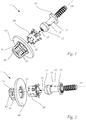
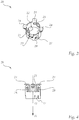
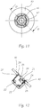
- the Figures 1 to 12 show a ball joint according to the invention for a vehicle headlight or its components
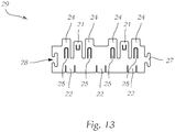
- the Figures 13 and 14 illustrate a manufacturing method for producing a socket for a ball joint
- the Figures 15 to 17 show a light module of a vehicle headlight, which has a ball joint according to the invention for a three-point suspension.
- a ball joint 1 which comprises a pivot pin 10, an articulation socket 20 and a support frame 40.
- the direction of installation 15 can be seen in which the pivot pin 10 can be inserted into the joint socket 20, and the installation direction 31, in which the joint socket 20 can be used in the support frame 40.
- the ball joint 1 comprises a joint pin 10, which comprises a joint ball 11 which merges on one side into an end face of an essentially cylindrical shaped joint shaft 12.
- the ball joint 1 consequently comprises a joint socket 20 for receiving the joint ball 11, wherein the joint socket 20 has a hollow cylindrical basic shape and consists of a resiliently elastic metal, preferably spring steel.
- the socket 20 is detailed in FIG 3 and 4 shown.
- two rear joint wings 21 are formed along the circumference of the hollow cylindrical joint socket 20, which are oriented against the installation direction 15 of the joint pin 10 and are inclined radially to the imaginary longitudinal axis 23 of the joint socket 20.
- three front joint wings 22 are formed on the joint socket 20 along the circumference of the hollow cylindrical joint socket 20, which are oriented in the installation direction 15 of the joint pin 10 and are inclined radially to the imaginary longitudinal axis 23 of the joint socket 20
- the two rear joint wings 21 and the three front joint wings 22 at least partially form an inner joint surface of the ball joint 1, which rests on the joint ball 11 in the assembled state of the ball joint 1.
- the inner joint surface does not bear against the joint ball 11 in a completely form-fitting manner, as a result of which the joint socket 20 can be produced particularly easily.
- an acetabular cup 20 can be provided, which has a significantly closer form fit between the joint ball 11 and the acetabular cup 20.
- Fig. 10 shows a pivot pin 10 inserted in the socket 20 indicated in dashed lines in a sectional plane CC Fig. 8 .
- a hinge edge 13 of a hinge pin can be seen (see also Fig. 1 and Fig. 6 ). It can also be seen that the joint edge 13 limits the joint surface of the joint ball 11 and that the joint socket 20 extends beyond the joint edge 13 and consequently a very high retention force of the fixed ball joint 1 can be achieved even if an imaginary longitudinal axis 14 of the joint pin 10 does not corresponds to an imaginary longitudinal axis 23 of the joint socket 20, that is to say if the joint pin 10 and the joint socket 20 are at an angle to one another in order, for example, to compensate for an assembly tolerance between the support frame 40 and a vehicle headlight which is mounted by means of the ball joint 1.
- an articulated edge 13 running along the circumference of the articulation socket 20 can optionally be formed on the surface of the articulated pin 10 between the articulated shaft 12 and the articulated ball 11, the articulated edge 13 preferably being formed by an intersection curve of the essentially concave surface of the articulated ball 11 and the convex Surface of the transition from the joint shaft 12 to the joint ball 11 is formed.
- the holding force of the ball joint 1 can be particularly great if the rear joint wings 21 extend at least as far as the joint edge 13 in an undisguised state in which an imaginary longitudinal axis 14 of the pivot pin 10 coincides with an imaginary longitudinal axis 23 of the joint socket 20.
- the two rear joint wings 21 are pressed against the joint ball 11 by spring force.
- each rear retaining wings 24 are arranged along the circumference of the hollow cylindrical joint socket 20, which are oriented against the installation direction 31 of the joint socket 20 and are radially inclined away from the imaginary longitudinal axis 23 of the joint socket 20 and the four rear Retaining wings 24 are set up, slipping of the joint socket 20 in the support frame 40 in To prevent installation direction 31 of the socket 20. This can prevent the joint socket 20 from being pressed too far into the support frame 40.
- four front retaining wings 25 are arranged for fastening the joint socket 20 to the support frame 40 along the circumference of the hollow cylindrical joint socket 20, which are oriented against the installation direction 31 of the joint socket 20 and are oriented normal to the imaginary longitudinal axis 23 of the joint socket 20, and the four front Retaining wings 25 are set up to prevent the joint socket 20 from slipping in the support frame 40 against the installation direction 31 of the joint socket 20. This can prevent the joint socket 20 from being pulled out of the support frame 40 again.
- Fig. 11 shows a plan view of the support frame 40, in which a joint socket 20 is inserted. Furthermore, a section plane DD can be seen, the view of which in Fig. 12 you can see.
- the front holding wings 25 and rear holding wings 24, which clamp the joint socket 20 in the support frame 40, can be clearly seen. This ensures a firm hold, which provides a stop with respect to the support frame 40 in both the pulling and pushing directions.
- the supporting frame 40 of the ball joint 1 for receiving the joint socket 20 at least partially encloses the two rear joint wings 21 of the joint socket 20, with which the so-called "springing open" of the joint wings can be prevented.
- the support frame 40 in this exemplary embodiment comprises three webs 41, which are arranged along the circumference of the opening of the support frame 40 and extend in the axial direction and are connected to one another by a web connector 42.
- the inner surfaces of the three webs 41 and / or the web connector 42 are at least partially complementary in shape with respect to the outer surface of the joint socket 20 and are designed to support the joint socket 20. This arrangement serves to stabilize the connection between the socket 20 and the support frame 40.
- the three webs 41 are oriented essentially parallel to the direction of installation of the socket 31. It is not essential whether the webs 41 are actually oriented parallel to the installation direction of the socket 31. Any design of the webs 41 is possible, which serves to support the hollow cylindrical joint socket 20.
- webs 41 are connected to one another at their ends via a circular web connector 42 in order to further improve the stability or the support of the joint socket 20.
- the webs 41 and the web connector 42 form a structure which is set up to accommodate the hollow cylindrical basic shape of the joint socket 20 and to improve its hold in the installation position. As a result, shear forces acting on the joint socket, which can be induced by the hinge pin or also by the support frame, can be reduced.
- the diameter of the joint ball 11 is larger than the radial diameter of the joint shaft 12.
- a transition between the joint shaft 12 and the joint ball 11 can be formed by a concave surface running along the circumference of the joint socket 20.
- the joint socket 20 is made in one piece from a flat and metallic material, preferably from sheet steel type 1.4310, and preferably a material thickness between 0.1 mm and 1 mm, particularly preferably between 0.3 mm and 0 , 7 mm, for example 0.5 mm.
- the socket 20 which further comprises two mutually complementarily shaped alignment elements 27, 28 which are arranged along the circumference of the socket 20 and are configured to engage with one another.
- the ball joint 1 is particularly suitable and intended to be arranged on or within a vehicle headlamp and is designed to fix the vehicle headlamp in an installed position.
- the ball joint 1 is particularly preferably suitable and intended to be installed in a carrier unit located on the vehicle side, the ball joint 1 connecting the carrier unit to the vehicle headlight, the vehicle headlight, in particular for generating a high beam and / or a low beam light distribution, is provided or to connect a headlight module fastened in a support frame to the headlight housing in an adjustable manner.
- FIG. 13 A blank 29 which has already been cut out is shown, from which a joint socket according to the invention can be formed.
- the three front hinged wings 22, the two rear hinged wings 21, the four rear retaining wings 24, the four front retaining wings 25 and the two alignment elements 27, 28 can be seen.
- the cutting process can be carried out by punching, sawing or cutting, preferably laser cutting, but in principle also using any other shaping method.
- Cut-out, U-shaped contours can be seen within the two rear joint wings 21, which serve to facilitate an additional curvature of the rear joint wings 21 by reducing the material cross-section in the rear joint wings 21 by the U-shaped cutout for easier bending.
- This additional curvature of the rear joint wings 21 is oriented outward in the radial socket 20, allows a very narrow bending radius due to the reduction in the material cross section, and ultimately facilitates the insertion of a joint ball 11 into the joint socket 20.
- the two complementary shaped alignment elements 27, 28 can be seen, which ensure that the joint socket is mechanically stable and precisely adjusted in the finished state.
- Fig. 14 shows an inventive method for producing a socket 20 for a ball joint 1, which comprises the following steps:
- the first method step is shown, that is to say the blank 29 of the joint socket 20 is cut from a flat material located in the plane 30, the blank 29 being completely cut in a plane 30 and preferably by laser cutting or punching.
- the second method step is shown, that is to say the bending of regions of the blank 29 which comprise the two rear joint wings 21, the three front joint wings 22, form the four rear retaining wings 24 and the four front retaining wings 25 of the joint socket 20, transverse to the plane 30.
- the two rear hinged wings 21 and the three front hinged wings 22 of the socket 20 are bent in the opposite direction normal to the plane 30 as the four rear retaining wings 24 and the four front retaining wings 25 of the socket 20, starting from the plane 30.
- regions of the blank 29 can be bent in two different directions in one process step or in two successive process steps.
- the third method step is shown, that is to say the shaping of the blank 29, so that the joint socket 20 is formed by rolling the blank 29 around the imaginary longitudinal axis 23 of the joint socket 20.
- Fig. 14d the last method step for manufacturing the socket 20 is shown, that is to say the connection or ring-shaped closing of the shaped blank 29 from the 14c , so that the two mutually complementarily shaped alignment elements 27, 28 engage in one another and thus have a precise adjustment to one another which is conducive to the mechanical stability of the joint socket 20.
- Fig. 15 shows a vehicle headlight 100 with a light module 101.
- Fig. 16 shows that the light module 101 can be mounted in the vehicle headlight 100 by a three-point suspension.
- the three-point suspension comprises a fixed leg 110, which is formed from the ball joint 1 according to the invention in accordance with the previous figures with the pivot pin 10, the joint socket 20 and a support frame, which in this example is part of the light module 101, and two adjustable legs 111, 112 , which are designed as adjusting screws and thus enable simple adjustment, and which preferably form an equilateral triangle with one another, with all triangular arrangements of the three legs being suitable in principle.
- the ball joint 1 on the fixed at 110 serves as the fixed point of the three-point suspension, which creates a spherically adjustable connection between the housing and the module.
- the light module 101 can be articulated with the vehicle headlight 100, a vehicle headlight component or a body part of a vehicle and offers the possibility of mutual fine adjustment.
- the pivot pin 10 has a thread on the pivot shaft 12, which can engage in an opening with a complementarily shaped internal thread and, when rotated in the internal thread, can perform a longitudinal movement in the direction of the imaginary longitudinal axis 14 of the pivot pin, as a result of which an additional adjustment movement of the Three-point suspension can be achieved.
- the pivot pin 10 can have, for example, a slot or a recess in the form of a hexagonal volume for receiving a corresponding screwdriver on its pivot ball 11, which is accessible through the light module 101.
- the support frame is shaped such that the holding wings 24, 25 of the joint sleeve 20 can snap into the support frame in order to be mechanically fixed.
- Fig. 17 shows the light module 101 according to FIG Fig. 16 in the assembled state of the ball joint, which forms a fixed leg 110 and together with the two adjustable legs 111, 112 forms the three-point suspension.
- the light module is provided in particular for generating a high beam and / or a low beam light distribution and may require a fine adjustment of the emitted light distribution according to operating regulations or legal installation regulations. It may also be necessary to repeat this fine adjustment during the operation of the vehicle.
Landscapes
- Engineering & Computer Science (AREA)
- General Engineering & Computer Science (AREA)
- Mechanical Engineering (AREA)
- Pivots And Pivotal Connections (AREA)
- Lighting Device Outwards From Vehicle And Optical Signal (AREA)
Claims (9)
- Articulation à rotule (1), destinée à fixer un projecteur dans un véhicule, comprenant un pivot d'articulation (10), qui comprend une rotule d'articulation (11) qui sur un côté, passe dans une face frontale d'une tige d'articulation (12) façonnée de manière sensiblement cylindrique, et une cavité d'articulation (20), destinée à recevoir la rotule d'articulation (1) et
le long de la périphérie de la cavité d'articulation (20) étant conçues au moins deux ailettes d'articulation (21) postérieures, qui sont orientés à l'encontre de la direction de montage (15) du pivot d'articulation (10) et qui sont inclinées radialement vers l'axe longitudinal (23) virtuel de la cavité d'articulation (20), et
le long de la périphérie de la cavité d'articulation (20) étant conçues au moins deux ailettes d'articulation (22) antérieures, qui sont orientées dans la direction de montage (15) du pivot d'articulation (10) et qui sont inclinées radialement vers l'axe longitudinal (23) virtuel de la cavité d'articulation (20),
les au moins deux ailettes d'articulation (21) postérieures et les au moins deux ailettes d'articulation (22) antérieures étant aménagées pour être adjacentes à la rotule d'articulation (11) et pour être pressées par une force de ressort contre la rotule d'articulation (11), et
le long de la périphérie de la cavité d'articulation étant placées au moins deux ailettes de maintien postérieures, qui sont orientées à l'encontre de la direction de montage de la cavité d'articulation et qui sont inclinées radialement en s'éloignant de l'axe longitudinal virtuel de la cavité d'articulation et les au moins deux ailettes de maintien postérieures étant aménagées pour empêcher un glissement de la cavité d'articulation dans le cadre de support dans la direction de montage de la cavité d'articulation, et
le long de la périphérie de la cavité d'articulation étant placées au moins deux ailettes de maintien antérieures, qui sont orientées à l'encontre de la direction de montage de la cavité d'articulation et qui sont inclinées radialement en s'éloignant de l'axe longitudinal virtuel de la cavité d'articulation, et les au moins deux ailettes de maintien antérieures étant aménagées pour empêcher un glissement de la cavité d'articulation dans le cadre de support, à l'encontre de la direction de montage de la cavité d'articulation,
caractérisée en ce que
la cavité d'articulation présente une forme de base en cylindre creux et est constituée d'un métal élastique résilient et l'articulation à rotule (1) comprend par ailleurs un cadre de support (40) pourvu d'un orifice, qui est apte à recevoir la cavité d'articulation (20) et le cadre de support (40) comprend par ailleurs au moins deux listels (41), de préférence au moins trois listels (41), qui sont placés le long de la périphérie de l'orifice du cadre de support (40) et qui s'étendent en direction axiale et qui sont reliés l'un à l'autre par au moins un connecteur de listels (42),
des surfaces internes des au moins deux listels (41) et/ ou de l'au moins un connecteur de listels (42) étant façonnées en complémentarité au moins partielle de la surface externe de la cavité d'articulation (20) et étant aménagées pour soutenir la cavité d'articulation (20), et le long de la périphérie de la cavité d'articulation (20) en forme de cylindre creux étant placées au moins deux ailettes de maintien (24) postérieures, qui sont orientées à l'encontre de la direction de montage (31) de la cavité d'articulation (20) et qui sont inclinées radialement en s'éloignant de l'axe longitudinal (23) virtuel de la cavité d'articulation (20) et les au moins deux ailettes de maintien (24) postérieures étant aménagées pour empêcher un glissement de la cavité d'articulation (20) dans le cadre de support (40), dans la direction de montage (31) de la cavité d'articulation (20), et
le long de la périphérie de la cavité d'articulation (20) en forme de cylindre creux étant placées au moins deux ailettes de maintien (25) antérieures, qui sont orientées à l'encontre de la direction de montage (31) de la cavité d'articulation (20) et qui et qui sont inclinées radialement en s'éloignant de l'axe longitudinal virtuel de la cavité d'articulation (20), qui sont orientées de préférence à la normale de l'axe longitudinal (23) virtuel de la cavité d'articulation (20) et les au moins deux ailettes de maintien (25) antérieures étant aménagées pour empêcher un glissement de la cavité d'articulation (20) dans le cadre de support (40), à l'encontre de la direction de montage (31) de la cavité d'articulation (20). - Articulation à rotule (1) selon la revendication 1, caractérisée en ce que le diamètre de la rotule d'articulation (11) est supérieur au diamètre radial de la tige d'articulation (12), et
un passage entre la tige d'articulation (12) et la rotule d'articulation (11) est formé par une surface convexe s'écoulant le long de la périphérie de la cavité d'articulation (20), et
sur la surface du pivot d'articulation (10), entre la tige d'articulation (12) et la rotule d'articulation (11) est conçue une arête d'articulation (13) s'écoulant le long de la périphérie de la cavité d'articulation (20), l'arête d'articulation (13) étant formée de préférence par une courbe d'intersection de la surface sensiblement concave de la rotule d'articulation (11) et de la surface convexe du passage de la tige d'articulation (12) vers la rotule d'articulation (11), et
dans un état de base, dans lequel un axe longitudinal (14) virtuel du pivot d'articulation (10) coïncide avec un axe longitudinal (23) virtuel de la cavité d'articulation (20), les ailettes d'articulation (21) s'étendent au moins jusqu'à l'arête d'articulation (13). - Articulation à rotule (1) selon la revendication 1 ou 2, caractérisée en ce que la cavité d'articulation (20) est fabriquée en monobloc en une matière plane et en une matière métallique, de préférence en tôle d'acier et présente une épaisseur de matière comprise entre 0,1 mm et 1 mm, de préférence entre 0,2 mm et 0,5 mm.
- Articulation à rotule (1) selon l'une quelconque des revendications 1 à 3, caractérisée en ce que la cavité d'articulation (20) comprend au moins deux éléments d'alignement (27, 28) complémentaires l'un de l'autre, qui sont placés le long de la périphérie de la cavité d'articulation (20) et qui sont aménagés pour s'engager l'un dans l'autre.
- Articulation à rotule (1) selon l'une quelconque des revendications 1 à 4, caractérisée en ce que l'articulation à rotule (1) est placée sur un ou à l'intérieur d'un projecteur de véhicule et est aménagée pour fixer le projecteur de véhicule dans une position de montage ou pour fixer des composants du projecteur dans le projecteur.
- Projecteur de véhicule, destiné à générer une distribution lumineuse de feu de route et/ ou une distribution lumineuse de feu de croisement, pourvu d'au moins une articulation à rotule (1) selon l'une quelconque des revendications 1 à 5, destinée à intégrer le projecteur de véhicule dans un véhicule, caractérisé en ce que l'articulation à rotule (1) relie une unité de support située sur le véhicule avec le projecteur de véhicule.
- Projecteur de véhicule, destiné à générer une distribution lumineuse de feu de route et/ ou une distribution lumineuse de feu de croisement, pourvu d'au moins une articulation à rotule (1) selon l'une quelconque des revendications 1 à 5, destinée à intégrer le projecteur de véhicule dans un véhicule, caractérisée en ce que l'articulation à rotule (1) forme une patte fixe (110), qui conjointement avec deux pattes (111, 112) réglables additionnelles forme une suspension à trois points, destinée à fixer un dispositif d'éclairage du projecteur de véhicule sur un composant de projecteur de véhicule ou sur une pièce de carrosserie du véhicule.
- Procédé, destiné à la fabrication d'une articulation à rotule (1) selon l'une quelconque des revendications 1 à 5, la cavité d'articulation (20) étant fabriquée selon les étapes suivantes, consistant à :couper une ébauche (29) de la cavité d'articulation (20) dans une matière plane, la coupe complète de l'ébauche (29) s'effectuant dans un plan (30) ;cintrer des zones de l'ébauche (29), qui forment les ailettes d'articulation (21) postérieures et/ ou les ailettes de maintien (24) postérieures de la cavité d'articulation (20) à la transversale du plan (30) ;façonner l'ébauche (29), de telle sorte que la cavité d'articulation (20) soit formée par enroulement de l'ébauche (29) autour de l'axe longitudinal (23) virtuel de la cavité d'articulation (20).
- Procédé, destiné à la fabrication d'une articulation à rotule (1) selon la revendication 8, comprenant l'étape suivante consistant à :
relier l'ébauche (29) façonnée, de sorte qu'au moins deux éléments d'alignement (27, 28) façonnés en complémentarité l'un de l'autre s'engagent l'un dans l'autre.
Applications Claiming Priority (1)
| Application Number | Priority Date | Filing Date | Title |
|---|---|---|---|
| ATA50011/2017A AT519541B1 (de) | 2017-01-10 | 2017-01-10 | Kugelgelenk |
Publications (2)
| Publication Number | Publication Date |
|---|---|
| EP3346148A1 EP3346148A1 (fr) | 2018-07-11 |
| EP3346148B1 true EP3346148B1 (fr) | 2020-03-11 |
Family
ID=60673541
Family Applications (1)
| Application Number | Title | Priority Date | Filing Date |
|---|---|---|---|
| EP17207207.6A Active EP3346148B1 (fr) | 2017-01-10 | 2017-12-14 | Joint pivotant |
Country Status (3)
| Country | Link |
|---|---|
| EP (1) | EP3346148B1 (fr) |
| CN (1) | CN108286565A (fr) |
| AT (1) | AT519541B1 (fr) |
Families Citing this family (8)
| Publication number | Priority date | Publication date | Assignee | Title |
|---|---|---|---|---|
| CN110279441A (zh) * | 2019-06-11 | 2019-09-27 | 中国人民解放军总医院 | 一种脊柱微创手术通道固定装置 |
| CN110146041A (zh) * | 2019-06-14 | 2019-08-20 | 陕煤集团神木张家峁矿业有限公司 | 一种地裂缝测量方法 |
| DE102020100014A1 (de) | 2020-01-02 | 2021-07-08 | HELLA GmbH & Co. KGaA | Fügeanordnung aufweisend ein Aufnahmemittel und ein Kugelgelenk |
| CN115667737B (zh) * | 2020-06-12 | 2025-08-22 | 株式会社利富高 | 球形接头 |
| CN114498418A (zh) * | 2021-12-22 | 2022-05-13 | 河南平高通用电气有限公司 | 一种带有手车的电气柜及用于与手车适配的静触头 |
| DE102023108378A1 (de) * | 2023-03-31 | 2023-05-17 | Daimler Truck AG | Umgebungsbeleuchtungseinrichtung eines Kraftfahrzeuges |
| CN116951258B (zh) * | 2023-07-07 | 2025-10-21 | 中山三禾影视器材有限公司 | 一种球体锁紧结构 |
| CN223484132U (zh) * | 2024-08-20 | 2025-10-28 | 东莞市昊恩装饰品有限公司 | 一种灯头连接结构、灯头及灯具 |
Family Cites Families (14)
| Publication number | Priority date | Publication date | Assignee | Title |
|---|---|---|---|---|
| JPH09204803A (ja) * | 1996-01-29 | 1997-08-05 | Koito Mfg Co Ltd | 前照灯のエイミング装置 |
| US6670553B1 (en) * | 1998-01-15 | 2003-12-30 | Arlington Industries, Inc. | Snap engagement electrical fitting for EMT |
| US6758622B2 (en) * | 2001-02-16 | 2004-07-06 | Burton Technologies Llc | Ball socket with improved pull-out force resistance |
| US7008135B2 (en) * | 2002-01-31 | 2006-03-07 | Guide Corporation | Stamped ball socket |
| FR2841945B1 (fr) * | 2002-07-04 | 2008-03-14 | Bosch Gmbh Robert | Dispositif a liaison rotulante et procede de montage associe. |
| US6837716B1 (en) * | 2003-07-02 | 2005-01-04 | Illinois Tool Works Inc. | Push-in ball socket |
| US7494157B1 (en) * | 2004-04-28 | 2009-02-24 | Bridgeport Fittings, Inc. | Electrical connector with snap fit retaining ring with improved holding and grounding tangs |
| GB0415333D0 (en) * | 2004-07-08 | 2004-08-11 | Ap France S A | Ball joint connectors |
| CN2804596Y (zh) * | 2005-04-22 | 2006-08-09 | 堤维西交通工业股份有限公司 | 灯座手动调整装置 |
| US7963715B2 (en) * | 2008-04-10 | 2011-06-21 | Burton Technologies, Llc | Push-in connector |
| JP5970187B2 (ja) * | 2008-11-12 | 2016-08-17 | ボーグワーナー インコーポレーテッド | ターボチャージャの連結ロッド |
| CN201989701U (zh) * | 2011-01-14 | 2011-09-28 | 帝宝工业股份有限公司 | 车灯调整机构的固定座结构 |
| US9140294B2 (en) * | 2012-03-06 | 2015-09-22 | Burton Technologies, Llc | High extraction force ball socket |
| CN205155784U (zh) * | 2015-10-30 | 2016-04-13 | 比亚迪股份有限公司 | 一种组合式led近光灯及其汽车 |
-
2017
- 2017-01-10 AT ATA50011/2017A patent/AT519541B1/de active
- 2017-12-14 EP EP17207207.6A patent/EP3346148B1/fr active Active
-
2018
- 2018-01-03 CN CN201810004316.6A patent/CN108286565A/zh active Pending
Non-Patent Citations (1)
| Title |
|---|
| None * |
Also Published As
| Publication number | Publication date |
|---|---|
| AT519541B1 (de) | 2018-10-15 |
| CN108286565A (zh) | 2018-07-17 |
| AT519541A1 (de) | 2018-07-15 |
| EP3346148A1 (fr) | 2018-07-11 |
Similar Documents
| Publication | Publication Date | Title |
|---|---|---|
| EP3346148B1 (fr) | Joint pivotant | |
| EP2470387B1 (fr) | Dispositif de montage pour un ressort à lame latéralement orienté | |
| EP2470384B1 (fr) | Dispositif de montage pour un ressort à lame latéralement orienté | |
| EP3099527B1 (fr) | Actionneur pour un véhicule automobile, notamment pour un siège de véhicule automobile | |
| EP3299642B1 (fr) | Optique de véhicule avec joint pivotant | |
| EP2270356B1 (fr) | Douille élastique | |
| EP2414180B1 (fr) | Articulation elastomere | |
| DE102012009173B4 (de) | Toleranzausgleichseinrichtung | |
| DE102009028893A1 (de) | Lagervorrichtung einer im Bereich einer Fahrzeugachse eines Fahrzeuges montierbaren Querblattfeder | |
| DE102009028899A1 (de) | Lagervorrichtung für eine Querblattfeder, die im Bereich einer Fahrzeugachse eines Fahrzeuges montierbar ist | |
| DE102009028895A1 (de) | Lagervorrichtung einer Querblattfeder | |
| DE102013214737A1 (de) | Lenkereinheit | |
| EP4378718B1 (fr) | Procédé de fabrication d'un élément de châssis | |
| DE102022104980A1 (de) | Lenkungsaktuator | |
| EP2621756A1 (fr) | Dispositif de réglage comportant une transmission à broche | |
| DE102012112362C5 (de) | Ventil mit einer Befestigungseinrichtung | |
| DE102018118340B4 (de) | Nutzfahrzeugachsaufhängung | |
| EP3028884B1 (fr) | Unité de support | |
| DE112006002662B4 (de) | Blattfeder mit im Querschnitt konvexer Ober-und Unterseite | |
| DE102024114742B3 (de) | Starres Verbindungsteil zur mechanischen Kopplung eines ersten Bauteils und eines zweiten Bauteils | |
| EP2708763B1 (fr) | Liaison rotule avec un élément mobile de verrouillage | |
| EP2893110B1 (fr) | Ensemble butée pour un élément pouvant changer de position, monté sur une carrosserie de véhicule | |
| DE202022104794U1 (de) | Einstellelement zur Einstellung eines Lichtmoduls | |
| EP3299646A1 (fr) | Douille et siège de véhicule | |
| DE202014105797U1 (de) | Halteeinheit |
Legal Events
| Date | Code | Title | Description |
|---|---|---|---|
| PUAI | Public reference made under article 153(3) epc to a published international application that has entered the european phase |
Free format text: ORIGINAL CODE: 0009012 |
|
| STAA | Information on the status of an ep patent application or granted ep patent |
Free format text: STATUS: THE APPLICATION HAS BEEN PUBLISHED |
|
| AK | Designated contracting states |
Kind code of ref document: A1 Designated state(s): AL AT BE BG CH CY CZ DE DK EE ES FI FR GB GR HR HU IE IS IT LI LT LU LV MC MK MT NL NO PL PT RO RS SE SI SK SM TR |
|
| AX | Request for extension of the european patent |
Extension state: BA ME |
|
| STAA | Information on the status of an ep patent application or granted ep patent |
Free format text: STATUS: REQUEST FOR EXAMINATION WAS MADE |
|
| STAA | Information on the status of an ep patent application or granted ep patent |
Free format text: STATUS: EXAMINATION IS IN PROGRESS |
|
| 17P | Request for examination filed |
Effective date: 20181115 |
|
| RBV | Designated contracting states (corrected) |
Designated state(s): AL AT BE BG CH CY CZ DE DK EE ES FI FR GB GR HR HU IE IS IT LI LT LU LV MC MK MT NL NO PL PT RO RS SE SI SK SM TR |
|
| 17Q | First examination report despatched |
Effective date: 20181207 |
|
| REG | Reference to a national code |
Ref country code: DE Ref legal event code: R079 Ref document number: 502017004178 Country of ref document: DE Free format text: PREVIOUS MAIN CLASS: F16C0011060000 Ipc: B60Q0001076000 |
|
| GRAP | Despatch of communication of intention to grant a patent |
Free format text: ORIGINAL CODE: EPIDOSNIGR1 |
|
| STAA | Information on the status of an ep patent application or granted ep patent |
Free format text: STATUS: GRANT OF PATENT IS INTENDED |
|
| RIC1 | Information provided on ipc code assigned before grant |
Ipc: B60Q 1/068 20060101ALI20190930BHEP Ipc: F16C 11/06 20060101ALI20190930BHEP Ipc: F16C 11/10 20060101ALI20190930BHEP Ipc: B60Q 1/076 20060101AFI20190930BHEP |
|
| INTG | Intention to grant announced |
Effective date: 20191018 |
|
| GRAS | Grant fee paid |
Free format text: ORIGINAL CODE: EPIDOSNIGR3 |
|
| GRAA | (expected) grant |
Free format text: ORIGINAL CODE: 0009210 |
|
| STAA | Information on the status of an ep patent application or granted ep patent |
Free format text: STATUS: THE PATENT HAS BEEN GRANTED |
|
| AK | Designated contracting states |
Kind code of ref document: B1 Designated state(s): AL AT BE BG CH CY CZ DE DK EE ES FI FR GB GR HR HU IE IS IT LI LT LU LV MC MK MT NL NO PL PT RO RS SE SI SK SM TR |
|
| REG | Reference to a national code |
Ref country code: GB Ref legal event code: FG4D Free format text: NOT ENGLISH |
|
| REG | Reference to a national code |
Ref country code: CH Ref legal event code: EP |
|
| REG | Reference to a national code |
Ref country code: AT Ref legal event code: REF Ref document number: 1242743 Country of ref document: AT Kind code of ref document: T Effective date: 20200315 |
|
| REG | Reference to a national code |
Ref country code: IE Ref legal event code: FG4D Free format text: LANGUAGE OF EP DOCUMENT: GERMAN |
|
| REG | Reference to a national code |
Ref country code: DE Ref legal event code: R096 Ref document number: 502017004178 Country of ref document: DE |
|
| PG25 | Lapsed in a contracting state [announced via postgrant information from national office to epo] |
Ref country code: NO Free format text: LAPSE BECAUSE OF FAILURE TO SUBMIT A TRANSLATION OF THE DESCRIPTION OR TO PAY THE FEE WITHIN THE PRESCRIBED TIME-LIMIT Effective date: 20200611 Ref country code: FI Free format text: LAPSE BECAUSE OF FAILURE TO SUBMIT A TRANSLATION OF THE DESCRIPTION OR TO PAY THE FEE WITHIN THE PRESCRIBED TIME-LIMIT Effective date: 20200311 Ref country code: RS Free format text: LAPSE BECAUSE OF FAILURE TO SUBMIT A TRANSLATION OF THE DESCRIPTION OR TO PAY THE FEE WITHIN THE PRESCRIBED TIME-LIMIT Effective date: 20200311 |
|
| REG | Reference to a national code |
Ref country code: NL Ref legal event code: MP Effective date: 20200311 |
|
| PG25 | Lapsed in a contracting state [announced via postgrant information from national office to epo] |
Ref country code: GR Free format text: LAPSE BECAUSE OF FAILURE TO SUBMIT A TRANSLATION OF THE DESCRIPTION OR TO PAY THE FEE WITHIN THE PRESCRIBED TIME-LIMIT Effective date: 20200612 Ref country code: HR Free format text: LAPSE BECAUSE OF FAILURE TO SUBMIT A TRANSLATION OF THE DESCRIPTION OR TO PAY THE FEE WITHIN THE PRESCRIBED TIME-LIMIT Effective date: 20200311 Ref country code: LV Free format text: LAPSE BECAUSE OF FAILURE TO SUBMIT A TRANSLATION OF THE DESCRIPTION OR TO PAY THE FEE WITHIN THE PRESCRIBED TIME-LIMIT Effective date: 20200311 Ref country code: SE Free format text: LAPSE BECAUSE OF FAILURE TO SUBMIT A TRANSLATION OF THE DESCRIPTION OR TO PAY THE FEE WITHIN THE PRESCRIBED TIME-LIMIT Effective date: 20200311 Ref country code: BG Free format text: LAPSE BECAUSE OF FAILURE TO SUBMIT A TRANSLATION OF THE DESCRIPTION OR TO PAY THE FEE WITHIN THE PRESCRIBED TIME-LIMIT Effective date: 20200611 |
|
| REG | Reference to a national code |
Ref country code: LT Ref legal event code: MG4D |
|
| PG25 | Lapsed in a contracting state [announced via postgrant information from national office to epo] |
Ref country code: NL Free format text: LAPSE BECAUSE OF FAILURE TO SUBMIT A TRANSLATION OF THE DESCRIPTION OR TO PAY THE FEE WITHIN THE PRESCRIBED TIME-LIMIT Effective date: 20200311 |
|
| PG25 | Lapsed in a contracting state [announced via postgrant information from national office to epo] |
Ref country code: CZ Free format text: LAPSE BECAUSE OF FAILURE TO SUBMIT A TRANSLATION OF THE DESCRIPTION OR TO PAY THE FEE WITHIN THE PRESCRIBED TIME-LIMIT Effective date: 20200311 Ref country code: RO Free format text: LAPSE BECAUSE OF FAILURE TO SUBMIT A TRANSLATION OF THE DESCRIPTION OR TO PAY THE FEE WITHIN THE PRESCRIBED TIME-LIMIT Effective date: 20200311 Ref country code: PT Free format text: LAPSE BECAUSE OF FAILURE TO SUBMIT A TRANSLATION OF THE DESCRIPTION OR TO PAY THE FEE WITHIN THE PRESCRIBED TIME-LIMIT Effective date: 20200805 Ref country code: IS Free format text: LAPSE BECAUSE OF FAILURE TO SUBMIT A TRANSLATION OF THE DESCRIPTION OR TO PAY THE FEE WITHIN THE PRESCRIBED TIME-LIMIT Effective date: 20200711 Ref country code: SK Free format text: LAPSE BECAUSE OF FAILURE TO SUBMIT A TRANSLATION OF THE DESCRIPTION OR TO PAY THE FEE WITHIN THE PRESCRIBED TIME-LIMIT Effective date: 20200311 Ref country code: SM Free format text: LAPSE BECAUSE OF FAILURE TO SUBMIT A TRANSLATION OF THE DESCRIPTION OR TO PAY THE FEE WITHIN THE PRESCRIBED TIME-LIMIT Effective date: 20200311 Ref country code: EE Free format text: LAPSE BECAUSE OF FAILURE TO SUBMIT A TRANSLATION OF THE DESCRIPTION OR TO PAY THE FEE WITHIN THE PRESCRIBED TIME-LIMIT Effective date: 20200311 Ref country code: LT Free format text: LAPSE BECAUSE OF FAILURE TO SUBMIT A TRANSLATION OF THE DESCRIPTION OR TO PAY THE FEE WITHIN THE PRESCRIBED TIME-LIMIT Effective date: 20200311 |
|
| REG | Reference to a national code |
Ref country code: DE Ref legal event code: R097 Ref document number: 502017004178 Country of ref document: DE |
|
| PLBE | No opposition filed within time limit |
Free format text: ORIGINAL CODE: 0009261 |
|
| STAA | Information on the status of an ep patent application or granted ep patent |
Free format text: STATUS: NO OPPOSITION FILED WITHIN TIME LIMIT |
|
| PG25 | Lapsed in a contracting state [announced via postgrant information from national office to epo] |
Ref country code: ES Free format text: LAPSE BECAUSE OF FAILURE TO SUBMIT A TRANSLATION OF THE DESCRIPTION OR TO PAY THE FEE WITHIN THE PRESCRIBED TIME-LIMIT Effective date: 20200311 Ref country code: IT Free format text: LAPSE BECAUSE OF FAILURE TO SUBMIT A TRANSLATION OF THE DESCRIPTION OR TO PAY THE FEE WITHIN THE PRESCRIBED TIME-LIMIT Effective date: 20200311 Ref country code: DK Free format text: LAPSE BECAUSE OF FAILURE TO SUBMIT A TRANSLATION OF THE DESCRIPTION OR TO PAY THE FEE WITHIN THE PRESCRIBED TIME-LIMIT Effective date: 20200311 |
|
| 26N | No opposition filed |
Effective date: 20201214 |
|
| PG25 | Lapsed in a contracting state [announced via postgrant information from national office to epo] |
Ref country code: PL Free format text: LAPSE BECAUSE OF FAILURE TO SUBMIT A TRANSLATION OF THE DESCRIPTION OR TO PAY THE FEE WITHIN THE PRESCRIBED TIME-LIMIT Effective date: 20200311 Ref country code: SI Free format text: LAPSE BECAUSE OF FAILURE TO SUBMIT A TRANSLATION OF THE DESCRIPTION OR TO PAY THE FEE WITHIN THE PRESCRIBED TIME-LIMIT Effective date: 20200311 |
|
| REG | Reference to a national code |
Ref country code: CH Ref legal event code: PL |
|
| PG25 | Lapsed in a contracting state [announced via postgrant information from national office to epo] |
Ref country code: MC Free format text: LAPSE BECAUSE OF FAILURE TO SUBMIT A TRANSLATION OF THE DESCRIPTION OR TO PAY THE FEE WITHIN THE PRESCRIBED TIME-LIMIT Effective date: 20200311 |
|
| REG | Reference to a national code |
Ref country code: BE Ref legal event code: MM Effective date: 20201231 |
|
| PG25 | Lapsed in a contracting state [announced via postgrant information from national office to epo] |
Ref country code: IE Free format text: LAPSE BECAUSE OF NON-PAYMENT OF DUE FEES Effective date: 20201214 Ref country code: LU Free format text: LAPSE BECAUSE OF NON-PAYMENT OF DUE FEES Effective date: 20201214 |
|
| PG25 | Lapsed in a contracting state [announced via postgrant information from national office to epo] |
Ref country code: LI Free format text: LAPSE BECAUSE OF NON-PAYMENT OF DUE FEES Effective date: 20201231 Ref country code: CH Free format text: LAPSE BECAUSE OF NON-PAYMENT OF DUE FEES Effective date: 20201231 |
|
| PG25 | Lapsed in a contracting state [announced via postgrant information from national office to epo] |
Ref country code: TR Free format text: LAPSE BECAUSE OF FAILURE TO SUBMIT A TRANSLATION OF THE DESCRIPTION OR TO PAY THE FEE WITHIN THE PRESCRIBED TIME-LIMIT Effective date: 20200311 Ref country code: MT Free format text: LAPSE BECAUSE OF FAILURE TO SUBMIT A TRANSLATION OF THE DESCRIPTION OR TO PAY THE FEE WITHIN THE PRESCRIBED TIME-LIMIT Effective date: 20200311 Ref country code: CY Free format text: LAPSE BECAUSE OF FAILURE TO SUBMIT A TRANSLATION OF THE DESCRIPTION OR TO PAY THE FEE WITHIN THE PRESCRIBED TIME-LIMIT Effective date: 20200311 |
|
| PG25 | Lapsed in a contracting state [announced via postgrant information from national office to epo] |
Ref country code: MK Free format text: LAPSE BECAUSE OF FAILURE TO SUBMIT A TRANSLATION OF THE DESCRIPTION OR TO PAY THE FEE WITHIN THE PRESCRIBED TIME-LIMIT Effective date: 20200311 Ref country code: AL Free format text: LAPSE BECAUSE OF FAILURE TO SUBMIT A TRANSLATION OF THE DESCRIPTION OR TO PAY THE FEE WITHIN THE PRESCRIBED TIME-LIMIT Effective date: 20200311 |
|
| PG25 | Lapsed in a contracting state [announced via postgrant information from national office to epo] |
Ref country code: BE Free format text: LAPSE BECAUSE OF NON-PAYMENT OF DUE FEES Effective date: 20201231 |
|
| GBPC | Gb: european patent ceased through non-payment of renewal fee |
Effective date: 20211214 |
|
| PG25 | Lapsed in a contracting state [announced via postgrant information from national office to epo] |
Ref country code: GB Free format text: LAPSE BECAUSE OF NON-PAYMENT OF DUE FEES Effective date: 20211214 |
|
| P01 | Opt-out of the competence of the unified patent court (upc) registered |
Effective date: 20230528 |
|
| REG | Reference to a national code |
Ref country code: AT Ref legal event code: MM01 Ref document number: 1242743 Country of ref document: AT Kind code of ref document: T Effective date: 20221214 |
|
| PG25 | Lapsed in a contracting state [announced via postgrant information from national office to epo] |
Ref country code: AT Free format text: LAPSE BECAUSE OF NON-PAYMENT OF DUE FEES Effective date: 20221214 |
|
| PG25 | Lapsed in a contracting state [announced via postgrant information from national office to epo] |
Ref country code: AT Free format text: LAPSE BECAUSE OF NON-PAYMENT OF DUE FEES Effective date: 20221214 |
|
| REG | Reference to a national code |
Ref country code: DE Ref legal event code: R084 Ref document number: 502017004178 Country of ref document: DE |
|
| PGFP | Annual fee paid to national office [announced via postgrant information from national office to epo] |
Ref country code: FR Payment date: 20251218 Year of fee payment: 9 |
|
| PGFP | Annual fee paid to national office [announced via postgrant information from national office to epo] |
Ref country code: DE Payment date: 20251222 Year of fee payment: 9 |
|
| PGFP | Annual fee paid to national office [announced via postgrant information from national office to epo] |
Ref country code: AT Payment date: 20260410 Year of fee payment: 5 |