EP3346162A1 - Linearer aktuator - Google Patents
Linearer aktuator Download PDFInfo
- Publication number
- EP3346162A1 EP3346162A1 EP18150477.0A EP18150477A EP3346162A1 EP 3346162 A1 EP3346162 A1 EP 3346162A1 EP 18150477 A EP18150477 A EP 18150477A EP 3346162 A1 EP3346162 A1 EP 3346162A1
- Authority
- EP
- European Patent Office
- Prior art keywords
- switch
- linear actuator
- driven nut
- differential
- conductive path
- Prior art date
- Legal status (The legal status is an assumption and is not a legal conclusion. Google has not performed a legal analysis and makes no representation as to the accuracy of the status listed.)
- Withdrawn
Links
Images




Classifications
-
- F—MECHANICAL ENGINEERING; LIGHTING; HEATING; WEAPONS; BLASTING
- F16—ENGINEERING ELEMENTS AND UNITS; GENERAL MEASURES FOR PRODUCING AND MAINTAINING EFFECTIVE FUNCTIONING OF MACHINES OR INSTALLATIONS; THERMAL INSULATION IN GENERAL
- F16H—GEARING
- F16H48/00—Differential gearings
- F16H48/20—Arrangements for suppressing or influencing the differential action, e.g. locking devices
- F16H48/30—Arrangements for suppressing or influencing the differential action, e.g. locking devices using externally-actuatable means
- F16H48/34—Arrangements for suppressing or influencing the differential action, e.g. locking devices using externally-actuatable means using electromagnetic or electric actuators
-
- F—MECHANICAL ENGINEERING; LIGHTING; HEATING; WEAPONS; BLASTING
- F16—ENGINEERING ELEMENTS AND UNITS; GENERAL MEASURES FOR PRODUCING AND MAINTAINING EFFECTIVE FUNCTIONING OF MACHINES OR INSTALLATIONS; THERMAL INSULATION IN GENERAL
- F16H—GEARING
- F16H25/00—Gearings comprising primarily only cams, cam-followers and screw-and-nut mechanisms
- F16H25/18—Gearings comprising primarily only cams, cam-followers and screw-and-nut mechanisms for conveying or interconverting oscillating or reciprocating motions
- F16H25/20—Screw mechanisms
- F16H25/2015—Means specially adapted for stopping actuators in the end position; Position sensing means
-
- F—MECHANICAL ENGINEERING; LIGHTING; HEATING; WEAPONS; BLASTING
- F16—ENGINEERING ELEMENTS AND UNITS; GENERAL MEASURES FOR PRODUCING AND MAINTAINING EFFECTIVE FUNCTIONING OF MACHINES OR INSTALLATIONS; THERMAL INSULATION IN GENERAL
- F16H—GEARING
- F16H48/00—Differential gearings
- F16H48/06—Differential gearings with gears having orbital motion
- F16H48/08—Differential gearings with gears having orbital motion comprising bevel gears
-
- F—MECHANICAL ENGINEERING; LIGHTING; HEATING; WEAPONS; BLASTING
- F16—ENGINEERING ELEMENTS AND UNITS; GENERAL MEASURES FOR PRODUCING AND MAINTAINING EFFECTIVE FUNCTIONING OF MACHINES OR INSTALLATIONS; THERMAL INSULATION IN GENERAL
- F16H—GEARING
- F16H48/00—Differential gearings
- F16H48/20—Arrangements for suppressing or influencing the differential action, e.g. locking devices
-
- F—MECHANICAL ENGINEERING; LIGHTING; HEATING; WEAPONS; BLASTING
- F16—ENGINEERING ELEMENTS AND UNITS; GENERAL MEASURES FOR PRODUCING AND MAINTAINING EFFECTIVE FUNCTIONING OF MACHINES OR INSTALLATIONS; THERMAL INSULATION IN GENERAL
- F16H—GEARING
- F16H48/00—Differential gearings
- F16H48/20—Arrangements for suppressing or influencing the differential action, e.g. locking devices
- F16H48/24—Arrangements for suppressing or influencing the differential action, e.g. locking devices using positive clutches or brakes
-
- H—ELECTRICITY
- H01—ELECTRIC ELEMENTS
- H01H—ELECTRIC SWITCHES; RELAYS; SELECTORS; EMERGENCY PROTECTIVE DEVICES
- H01H3/00—Mechanisms for operating contacts
- H01H3/02—Operating parts, i.e. for operating driving mechanism by a mechanical force external to the switch
- H01H3/16—Operating parts, i.e. for operating driving mechanism by a mechanical force external to the switch adapted for actuation at a limit or other predetermined position in the path of a body, the relative movement of switch and body being primarily for a purpose other than the actuation of the switch, e.g. for a door switch, a limit switch, a floor-levelling switch of a lift
-
- F—MECHANICAL ENGINEERING; LIGHTING; HEATING; WEAPONS; BLASTING
- F16—ENGINEERING ELEMENTS AND UNITS; GENERAL MEASURES FOR PRODUCING AND MAINTAINING EFFECTIVE FUNCTIONING OF MACHINES OR INSTALLATIONS; THERMAL INSULATION IN GENERAL
- F16H—GEARING
- F16H25/00—Gearings comprising primarily only cams, cam-followers and screw-and-nut mechanisms
- F16H25/18—Gearings comprising primarily only cams, cam-followers and screw-and-nut mechanisms for conveying or interconverting oscillating or reciprocating motions
- F16H25/20—Screw mechanisms
- F16H2025/2062—Arrangements for driving the actuator
- F16H2025/2081—Parallel arrangement of drive motor to screw axis
-
- F—MECHANICAL ENGINEERING; LIGHTING; HEATING; WEAPONS; BLASTING
- F16—ENGINEERING ELEMENTS AND UNITS; GENERAL MEASURES FOR PRODUCING AND MAINTAINING EFFECTIVE FUNCTIONING OF MACHINES OR INSTALLATIONS; THERMAL INSULATION IN GENERAL
- F16H—GEARING
- F16H48/00—Differential gearings
- F16H48/20—Arrangements for suppressing or influencing the differential action, e.g. locking devices
- F16H48/30—Arrangements for suppressing or influencing the differential action, e.g. locking devices using externally-actuatable means
- F16H48/34—Arrangements for suppressing or influencing the differential action, e.g. locking devices using externally-actuatable means using electromagnetic or electric actuators
- F16H2048/343—Arrangements for suppressing or influencing the differential action, e.g. locking devices using externally-actuatable means using electromagnetic or electric actuators using a rotary motor
-
- F—MECHANICAL ENGINEERING; LIGHTING; HEATING; WEAPONS; BLASTING
- F16—ENGINEERING ELEMENTS AND UNITS; GENERAL MEASURES FOR PRODUCING AND MAINTAINING EFFECTIVE FUNCTIONING OF MACHINES OR INSTALLATIONS; THERMAL INSULATION IN GENERAL
- F16H—GEARING
- F16H48/00—Differential gearings
- F16H48/20—Arrangements for suppressing or influencing the differential action, e.g. locking devices
- F16H48/30—Arrangements for suppressing or influencing the differential action, e.g. locking devices using externally-actuatable means
- F16H48/34—Arrangements for suppressing or influencing the differential action, e.g. locking devices using externally-actuatable means using electromagnetic or electric actuators
- F16H2048/346—Arrangements for suppressing or influencing the differential action, e.g. locking devices using externally-actuatable means using electromagnetic or electric actuators using a linear motor
Definitions
- Vehicles employ one or more differentials to allow an outer drive wheel to rotate faster than an inner drive wheel during cornering as both drive wheels continue to receive torque from an engine. While differentials are useful during cornering, they may allow the vehicle to lose traction, for example in mud, snow or other slick medium. Limited-slip differentials have been developed to address this loss of traction issue. Moreover, some types of vehicles, such as, but not limited to, recreational vehicles including all-terrain vehicles (ATVs) and utility task vehicles (UTVs) implement front and rear locking differentials to accommodate vehicle operational characteristic preferences. The locking mechanism of locking differentials selectively lock rotation of the drive wheels together based on a desired operational characteristic. A typical locking system employs a solenoid that requires a constant current draw during implementation of the locking system.
- ATVs all-terrain vehicles
- UUVs utility task vehicles
- Embodiments provide a linear actuator locking system that selectively locks a differential or other component without requiring a constant current draw to be maintained after implementation of a locking feature of the system. Moreover, embodiments of the linear actuator are effective, efficient, compact, simple and affordable.
- a linear actuator that includes a torque generator, a lead screw, a driven nut, an activation circuit and a push rod
- the torque generator has an output shaft.
- the lead screw is operationally coupled to the output shaft of the torque generator.
- the driven nut has an internally threaded bore that threadably engages external threads of the lead screw in such a manner that frictional forces between the internal threaded bore and the external threads prevent movement between the driven nut and the lead screw when no torque is provided by the torque generator.
- the activation circuit is in communication with the torque generator.
- the activation circuit has at least one switch that is configured to be activated by the driven nut.
- the push rod is operationally coupled to the driven nut.
- a differential with a linear actuator lock that includes a shift dog, a shift fork, an electric motor, a lead screw, a driven nut, an activation circuit and a push rod.
- the shift dog is configured to selectively engage a portion of the differential to selectively lock the differential.
- the shift fork is operationally engaged with the shift dog wherein movement of the shift fork moves the shift dog.
- the electric motor has an output shaft.
- the lead screw is operationally coupled to the output shaft of the electric motor.
- the driven nut has an internally threaded bore that threadably engages external threads of the lead screw in such a manner that frictional forces between the internal threaded bore and the external threads prevent movement between the driven nut and the lead screw when no torque is provided by the torque generator.
- the activation circuit is in communication with the electric motor.
- the activation circuit has at least one switch that is configured to be activated by the driven nut.
- the push rod is operationally coupled to the driven nut.
- the push rod is further operational
- a vehicle including an engine, a transmission, at least one differential and at least one linear actuator.
- the transmission is operationally coupled to the engine.
- the at least one differential is operationally coupled to the transmission.
- the at least one linear actuator is used to selectively lock the at least one differential.
- the at least one linear actuator includes an electric motor, a lead screw, a driven nut, an activation circuit and a push rod.
- the electric motor has an output shaft.
- the lead screw is operationally coupled to the output shaft of the electric motor.
- the driven nut has an internally threaded bore that threadably engages external threads of the lead screw in such a manner that frictional forces between the internal threaded bore and the external threads prevent movement between the driven nut and the lead screw when no torque is provided by the torque generator.
- the activation circuit is in communication with the electric motor.
- the activation circuit has at least one switch that is configured to be activated by the driven nut.
- the push rod is operationally coupled to the driven nut.
- a method of selectively locking a differential includes applying a current in a first direction to an electric motor to move a driven nut on a lead screw that is operationally coupled to the electric motor.
- a push rod is moved with the driven nut.
- the push nut is operationally engaged with a shift dog that is configured to engage a portion of the differential to selectively lock the differential upon movement of the push rod.
- At least a first switch is activated to remove the current to the electric motor once the shift dog has locked the differential, wherein a configuration of the driven nut on the lead screw retains the differential in a locked configuration after the current has been removed from the electric motor.
- Embodiments of the present invention provide an actuation system and method to engage and disengage a vehicle (such as, but no limited to ATV/UTV) front and/or rear locking differential.
- a vehicle such as, but no limited to ATV/UTV
- Embodiment may also be implemented in a disconnect system to selectively engage and disengage two wheel drive to four wheel drive in a vehicle.
- Embodiments do not require an electrical current once the motion of locking feature has been completed.
- embodiments provide a compact, efficient, and low cost locking mechanism.
- the linear actuator 100 includes a direct current motor 102 (or torque generator).
- a gear reduction train that includes a first gear 104 and a second gear 105 is rotationally coupled to a rotation output shaft 103 of the motor 102.
- the gear reduction train is operationally coupled to move a push rod 106 a defined distance to activate a mechanism inside a gearbox (such as, but not limited to, a differential such as differential 200 shown in Figure 2 ).
- Rotational motion of the output shaft 103 of the motor 102 is converted into linear motion via lead screw 108.
- the second gear 105 of the gear reduction train is rotationally coupled to the lead screw 108 to convey rotation of the output shaft 103 of the motor 102 to the lead screw 108.
- the lead screw 108 includes external threads 108a that engage internal threads of a driven nut 110 as best illustrated in Figure 2 .
- a first end 106a of the push rod 106 is held in a holding bore 110a of the driven nut 110. This connection causes the push rod 106 to linearly move with the driven nut 110.
- Two electrical mechanical switches 306 and 308 are used to control the distance of travel of the push rod 106 and driven nut 110.
- the electrical switches 306 and 308 are mounted in a first housing portion 114a via fasteners 115.
- the first housing portion 114a is mounted to a second housing portion 114b via fasteners 117.
- the components are sealed within the housing (114a and 114b) via seal between the housings portions 114a and 114b (not shown) and seal 120.
- Seal 120 is positioned about an internal passage of the first housing 114a and the push rod 106.
- Further seal 121 creates a seal between the linear actuator 100 and a housing of the differential 200 or other device.
- a washer 122 that is positioned to engage a shoulder of the push rod 106 and a retaining clip 124 that is engaged proximate a second end 106b of the push rod 106.
- Figure 2 illustrates a differential 200 including the linear actuator 100 of Figure 1 .
- the push rod 106 is operationally engaged with a shift fork 202 in the differential 200.
- the shift fork 202 in turn is engaged with an engagement dog 204 that selectively locks the differential 200.
- a biasing member 206 that is positioned between the shift fork 202 and the washer 122 and retaining clip 124 arrangement on the push rod 106, is used at least in part to manipulate the movement of the shift fork 202.
- the differential 200 in this example embodiment is illustrated as including a ring gear 250, a carrier 252, a first side gear 254a, a second side gear 254b and a first pinion gear 256.
- a second pinon gear is not illustrated in this cross-sectional side view.
- the engagement dog 204 is configured to selectively engage the first side gear 254a in this example embodiment to selectively lock the differential 200.
- shift fork 202 under control of the linear actuator 100, selectively slides the engagement dog 204 to engage the first side gear 254a to lock the differential.
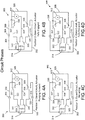
- FIG. 3 illustrates an activation circuit 300 used to operate the linear actuator 100 in an embodiment.
- the activation circuit 300 is reconfigurable via double pole double throw (DPDT) switch 302 that works with the first switch 306 and the second switch 308 to selectively operate motor 102.
- the circuit 300 includes a power supply 314. Electrically coupled to the power supply 314 is the DPDT switch 302.
- the DPDT switch 302 include a first pole 303 that is selectively positioned to make an electrical connection between a first side of the power supply (positive polarity side in this example) and a first conductive path 322 or a second conductive path 324.
- the DPDT switch 302 further includes a second pole 305 that is selectively positioned to make an electrical connection between a second side of the power supply (negative polarity side in this example) and the second conductive path 324 or a third conductive path 326.
- the first switch 306 includes a pole 307 that is selectively positioned to make an electrical connection between the first conductive path 322 and a fourth conductive path 328 or a fifth conductive path 330.
- the fifth conductive path 330 is couple to the second side of the power supply 314.
- the second switch 308 includes a pole 309 that is selectively positioned to make an electrical connection between the third conductive path 326 and the fourth conductive path 328 or a sixth conductive path 332.
- the sixth conductive path is coupled to the first side of the power supply 314.
- a first electrical connection of the motor 102 is coupled to the second conductive path 324 and a second electrical connection of the motor is coupled to the fourth conductive path 328.
- Positioned in the fifth conductive path 330 is a first indicator 304 and positioned within the sixth conductive path 332 is a second indicator 310.
- Figure 4A illustrates an actuator plunging forward configuration.
- the circuit 300 is closed activating the motor 312 to move the push rod 106 towards the shift fork 202 to move the shift fork 202 and the engagement dog 204.
- the first pole 303 of the DPDT switch 302 couples the first side (positive polarity side in this example) of the power supply 314 to the first conductive path 322.
- Pole 307 of the first switch 306 is positioned to connect the first conductive path 322 to the fourth conductive path 328.
- the second pole 305 of the DPDT switch 302 in this configuration connects the second side (negative polarity side in this example) to the second conductive path 324.
- current from the power supply 314 in this configuration passes through the second conductive path 324, through the motor 102 back to the power supply 302 via fourth and first conductive paths 328 and 322.
- the current flowing through the motor 102 in this direction causes the output shaft 103 of the motor 102 to rotate in a direction that causes the push rod 106 to move towards the shift fork 202 and activate the engagement dog 204.
- Figure 4B illustrates an actuator fully engaged configuration of the activation circuit 300.
- the first and second poles 303 and 305 of the DTDP switch 302 and pole 309 of the second switch 308 remain in the same position as in the actuator plunging forward configuration discussed above, but pole 307 of the first switch 306 is positioned to couple the first conductive path 322 to the fifth conductive path 330.
- current is not passing through the motor 102 (open circuit) in this configuration and hence the output shaft 103 of the motor 102 is not rotating.
- This configuration is implement when the push rod 106 has fully engaged the shift fork 202 in locking the differential 200 via the engagement dog 204.
- Indicator 304 indicates the linear actuator 100 has locked the differential 200.
- Figure 4C illustrates an actuator retracting configuration of the activation circuit 300.
- the first pole 303 of the DPDT switch 302 couples the first side of the power supply 314 (the positive polarity side) to the second conductive path 324 and the second pole 305 of the DPDT switch 302 couples the second side of the power supply 314 to the third conductive path 326.
- pole 307 of the first switch 306 is positioned to couple the first conductive path 322 to the fourth conductive path 328 and pole 309 of the second switch 308 couples the third conductive path 326 to the fourth conductive path 328.
- Figure 4D illustrates an actuator fully retracted configuration of the activation circuit 300.
- the first and second poles 303 and 305 of the DPDT switch 302 and pole 307 of the first switch 306 remain in the same position as in the actuator retraction configuration.
- pole 309 of the second switch 308 is positioned to couple the third conductive path 326 to the sixth conductive path 332 therein ceasing the current path through the motor 102.
- This actuator fully retracted configuration is implemented once the push rod 106 has is no longer working on the shift fork 202 and the differential is no longer locked.
- Indictor 310 is used to indicate the differential is not locked.
- the indicators 304 and 310 are position detectors that detect the position of a component of the actuator, such as the push rod 106 or the driven nut 110, at the end of a stroke to determine if the differential is locked or not.
- the indicators 304 and 310 use LED lights. However, other types of indicators are contemplated.
- Figure 5 illustrates a block diagram of a control system 500 of an embodiment.
- the control system 500 includes an input 504.
- the input 504 is an operator input that is used by the operator to select when to activate the linear actuator 502.
- a controller is used to activate the linear actuator 502 based on sensors inputs indicating a then current operational state of a vehicle implementing the linear actuator 502.
- the input 504, in the embodiment of Figure 5 controls the DPDT switch 302.
- the DPDT switch 302 controls the actuator 502, which in an embodiment, includes the push rod 106/driven nut 110 arrangement discussed above.
- the actuator 502 in turn controls switches 306 and 308.
- switches 306 and 308 may be operationally positioned to activate upon the completion of a stroke of the push rod 106, driven nut 110 or other component of the actuator 502.
- a position of a component of the actuator 502 at the end of the lock stroke activates switch 306, to cause the motor 312 to cease operation.
- a position of a component of the actuator 502 at the end of the unlock stroke activates switch 308, to cause the motor 312 to cease operation.
- the movement of the component of the actuator 502 at the beginning of a respective stroke further activates a respective switch 306 or 308 to set the poles of the respective switches 306 or 308 in a correct position for operation.
- the linear actuator 600 includes a direct current motor 602.
- a gear reduction train that includes a first gear 604 and a second gear 605 is rotationally coupled to a rotation output shaft 603 of the motor 602.
- the gear reduction train is operationally coupled to move a push rod 606 a defined distance to activate a mechanism inside a gearbox (such as, but not limited to, a differential such as differential 200 shown in Figure 2 ).
- Rotational motion of the output shaft 603 of the motor 602 is converted into linear motion via lead screw 608.
- the second gear 605 of the gear reduction train is rotationally coupled to the lead screw 608 to convey rotation of the output shaft 603 of the motor 602 to the lead screw 608.
- the lead screw 608 includes external threads 608a that engage internal threads 610a in a threaded bore 611 of a driven nut 610 as best illustrated in the close up cross sectional view of Figure 8 .
- a first end 606a of the push rod 606 is held in a holding bore 610b of the driven nut 610. This connection causes the push rod 606 to linearly move with the driven nut 610.
- Two electrical mechanical switches 806 and 808 are used to control the distance of travel of the push rod 606 and driven nut 610 as best illustrated in the cross sectional view of Figure 7 .
- the electrical switches 806 and 808 are mounted in a first housing portion 614a via fasteners 615.
- Switches 806 and 808 include switch manipulation portions 806a and 808a respectfully that are selectively activated by the driven nut 610 as the driven nut moves along the lead screw 608.
- linear actuator 600 of Figure 6 includes a circuit board 605 that includes the wiring to the switches and in an embodiment includes a controller as discussed above.
- the fasteners 615 also fasten the circuit board 605 to the first housing portion in this example embodiment.
- the linear actuator 600 is illustrated in the cross sectional side perspective view of Figure 7 as being in an extended state. This corresponds to position two: open circuit, actuator fully engaged configuration circuit of Figure 4B illustrated above using switch 806 in place of switch 306 and switch 808 in place of switch 308.
- the manipulation portion 806a of the switch 806 is triggered by the driven nut 610 to achieve the open circuit.
- Mechanical movement of the linear actuator 600 is locked in a static configuration by the interface between the external threads 608a of the lead screw 108 and the internal treads 610a in the threaded bore 611 of the driven nut 610.
- the first housing portion 614a is mounted to a second housing portion 614b via fasters 617.
- the components are sealed within the housing (614a and 614b) via seal between the housings portions 614a and 614b (not shown) and seal 620.
- Seal 621 creates a seal between the linear actuator 600 and a device housing, such as a differential housing.
- a washer 622 that is positioned to engage a shoulder of the push rod 606 and a retaining clip 624 that is engaged proximate a second end 606b of the push rod 606.
- a vehicle 700 implementing embodiments of the linear actuator is illustrated.
- the vehicle includes, an engine 702 to provide torque.
- a transmission 704 is operationally coupled to the engine 702.
- the transmission 704 in this embodiment includes a first output to a rear drive shaft 708 and a second output that is operationally coupled to a disconnect 706 in this embodiment.
- a front drive shaft 710 is operationally positioned between the disconnect 706 and a front differential 714.
- the front differential 714 is operationally coupled to a pair of front wheels 720a and 720b.
- the rear drive shaft 708 is operationally coupled to the rear differential 712 which is in turn operationally coupled to a pair of rear wheels 720c and 720d.
- a linear actuator 750 similar to linear actuator 100 or 600, is used to selectively connect and disconnect a rotational output of the transmission 704 to the front drive shaft 710 therein selecting between two wheel and four wheel drive.
- the disconnect 706 is illustrated between the transmission 704 and front drive shaft 710 in another embodiment it is positioned between the front differential 714 and the front drive shaft 710.
- both the front differential 714 and the rear differential 712 include linear actuators 752 and 754 respectively, similar to linear actuator 100 or 600 and differential 200 configuration described above.
- Other vehicle embodiments may implement less or more linear actuators 100 or 600 depending on the desired requirements of the vehicle.
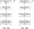
- Figure 10A illustrates a locking flow diagram 900 for a differential and Figure 10B illustrates an unlocking flow diagram 910 of exemplary embodiments.
- the flow diagrams 900 and 910 are provided as a series of sequential steps. The steps may occur in other orders. Hence, embodiments are not limited to the sequence of steps provided in Figures 10A and 10B .
- the locking flow diagram 900 starts by applying a current in a first direction to the electric motor at step (902). This will occur when it is desired for the differential to be locked.
- the applying of the current can be done under the control of a controller monitoring the current state of a vehicle using the differential or by a manual switch controlled by the operator.
- a push rod In response the current in the first direction, a push rod is moved in a first direction at step (904).
- the push rod is in communication with a shift dog in an embodiment that selectively locks the differential upon movement of the push rod in the first direction.
- a first switch is activated to remove the current at step (906). The different remains in the locked configuration after the current is removed from the electric motor at step (908). As discussed above this is done by the frictional configuration of the driven nut on the lead screw.
- the unlocking flow diagram 910 starts by applying a current in a second direction to the electric motor at step (912). This will occur when it is desired for the differential to be unlocked.
- the applying of the current can be done under the control of a controller monitoring the current state of a vehicle using the differential or by a manual switch controlled by the operator as discussed above.
- the push rod is moved in a second direction at step (914).
- the push rod is in communication with a shift dog in an embodiment that selectively unlocks the differential upon movement of the push rod in the second direction.
- a second switch is activated to remove the current at step (916).
- the different remains in the unlocked configuration after the current is removed from the electric motor at step (918). As discussed above this is done by the frictional configuration of the driven nut on the lead screw.
Landscapes
- Engineering & Computer Science (AREA)
- General Engineering & Computer Science (AREA)
- Mechanical Engineering (AREA)
- Physics & Mathematics (AREA)
- Electromagnetism (AREA)
- Arrangement And Mounting Of Devices That Control Transmission Of Motive Force (AREA)
- Gear-Shifting Mechanisms (AREA)
Applications Claiming Priority (1)
| Application Number | Priority Date | Filing Date | Title |
|---|---|---|---|
| US201762443184P | 2017-01-06 | 2017-01-06 |
Publications (1)
| Publication Number | Publication Date |
|---|---|
| EP3346162A1 true EP3346162A1 (de) | 2018-07-11 |
Family
ID=60954867
Family Applications (1)
| Application Number | Title | Priority Date | Filing Date |
|---|---|---|---|
| EP18150477.0A Withdrawn EP3346162A1 (de) | 2017-01-06 | 2018-01-05 | Linearer aktuator |
Country Status (2)
| Country | Link |
|---|---|
| US (1) | US10415681B2 (de) |
| EP (1) | EP3346162A1 (de) |
Families Citing this family (6)
| Publication number | Priority date | Publication date | Assignee | Title |
|---|---|---|---|---|
| US10683921B2 (en) * | 2017-03-08 | 2020-06-16 | Thomson Industries, Inc. | Differential lock actuation and control |
| JP2019027525A (ja) * | 2017-07-31 | 2019-02-21 | 株式会社ジェイテクト | 差動装置及び差動装置の調整方法 |
| JP7296453B2 (ja) | 2019-04-17 | 2023-06-22 | ジーケーエヌ オートモーティブ リミテッド | 時限的に差動可能なファイナルドライブギア装置 |
| US11353099B2 (en) * | 2020-01-03 | 2022-06-07 | Zhejiang CFMOTO Power Co., Ltd. | Actuator for differential mode shift with position sensing circuit |
| TWI717252B (zh) * | 2020-04-06 | 2021-01-21 | 介隆興齒輪股份有限公司 | 線性運動電控盒 |
| US11255421B2 (en) * | 2020-05-27 | 2022-02-22 | New Kailung Gear Co., Ltd. | Electric control box for control of linear movement |
Citations (5)
| Publication number | Priority date | Publication date | Assignee | Title |
|---|---|---|---|---|
| DE1555400A1 (de) * | 1966-03-31 | 1970-10-15 | Ford Motor Co | Sperre fuer das Differentialgetriebe eines Kraftfahrzeuges |
| JPH04317537A (ja) * | 1991-04-17 | 1992-11-09 | Fuji Electric Co Ltd | 電動機を備えるねじ伝動装置 |
| DE10030409A1 (de) * | 1999-11-09 | 2001-05-17 | Hiwin Mikrosystem Corp | Verstellantrieb mit Endlageschalter |
| JP2008095711A (ja) * | 2006-10-05 | 2008-04-24 | Kanzaki Kokyukoki Mfg Co Ltd | デフギア装置 |
| EP2202870A2 (de) * | 2008-12-26 | 2010-06-30 | Nabtesco Corporation | Elektrischer Schalter |
Family Cites Families (30)
| Publication number | Priority date | Publication date | Assignee | Title |
|---|---|---|---|---|
| US2444886A (en) * | 1945-04-09 | 1948-07-06 | Theodore W Vickers | Screw and nut actuating mechanism |
| US4425814A (en) * | 1981-03-23 | 1984-01-17 | Dana Corporation | Torque limiting device |
| US4440035A (en) * | 1981-05-18 | 1984-04-03 | Dana Corporation | Slip clutch speed change mechanism |
| US4498350A (en) * | 1982-09-20 | 1985-02-12 | Eaton Corporation | Shifting mechanism |
| BR8507238A (pt) | 1984-08-29 | 1987-10-27 | Zahnradfabrik Friedrichshafen | Ativacao de uma borboleta diferencial |
| US4805486A (en) | 1986-06-04 | 1989-02-21 | Tochigifujisangyo Kabushiki Kaisha | Locking differential gear assembly |
| JPS63203958A (ja) | 1987-02-20 | 1988-08-23 | Aisin Warner Ltd | 摩擦係合装置用アクチユエ−タ |
| US4793458A (en) * | 1987-11-09 | 1988-12-27 | Dana Corporation | Shift motor assembly for a two-speed axle |
| US4838118A (en) | 1988-03-10 | 1989-06-13 | Eaton Corporation | Anti-spin differential |
| US5279401A (en) | 1988-11-08 | 1994-01-18 | Uni-Cardan Ag | Method for controlling friction clutches or brakes |
| DE3915959A1 (de) | 1989-05-18 | 1990-11-22 | Gkn Automotive Ag | Ausgleichsgetriebe |
| US5353902A (en) * | 1992-06-16 | 1994-10-11 | Dana Corporation | Electric actuator assembly for clutch |
| US5267635A (en) * | 1992-07-13 | 1993-12-07 | Automotive Products Plc | Clutch actuator system |
| DE19527893C1 (de) * | 1995-07-29 | 1996-10-31 | Ford Werke Ag | Elektrische Schaltvorrichtung für Wechselgetriebe von Kraftfahrzeugen |
| US5878624A (en) * | 1997-06-06 | 1999-03-09 | Borg-Warner Automotive, Inc. | Single rail shift operator assembly |
| JP3706775B2 (ja) | 1999-07-29 | 2005-10-19 | 本田技研工業株式会社 | 小型乗用車両 |
| US6503167B1 (en) * | 2000-09-28 | 2003-01-07 | Spicer Technology, Inc. | Externally actuated locking differential assembly |
| CN100348832C (zh) * | 2006-10-18 | 2007-11-14 | 南京康尼机电新技术有限公司 | 无源螺旋门机锁闭机构 |
| US7896120B2 (en) | 2008-04-02 | 2011-03-01 | Yamaha Hatsudoki Kabushiki Kaisha | Small-sized vehicle with improved drivetrain |
| US20110269595A1 (en) | 2010-04-30 | 2011-11-03 | American Axle & Manufacturing Inc. | Control strategy for operating a locking differential |
| ES2668870T3 (es) | 2010-12-16 | 2018-05-22 | Polaris Industries Inc. | Sistema de tracción de modo múltiple |
| DE102011007253A1 (de) * | 2011-04-13 | 2012-10-18 | Schaeffler Technologies AG & Co. KG | Getriebeeinrichtung z.B. für eine elektrische Achse sowie elektrische Achse mit der Getriebeeinrichtung |
| TWM453059U (zh) * | 2012-12-24 | 2013-05-11 | Timotion Technology Co Ltd | 線性致動器及其搖臂驅動機構 |
| WO2015149874A1 (de) * | 2014-04-04 | 2015-10-08 | Gkn Driveline International Gmbh | Antriebsanordnung für ein kraftfahrzeug |
| WO2016014827A1 (en) | 2014-07-25 | 2016-01-28 | Eaton Corporation | Compact electronically controlled front wheel drive torque vectoring system with single or dual axle modulation |
| WO2016014823A1 (en) | 2014-07-25 | 2016-01-28 | Eaton Corporation | Electromechanical clutch actuation system for limited slip differential |
| CN104534086B (zh) | 2014-12-23 | 2017-04-12 | 东风汽车公司 | 电控式差速锁控制机构及控制方法 |
| US10343519B2 (en) * | 2016-06-23 | 2019-07-09 | Dana Heavy Vehicle Systems Group, Llc | Mechanical shift assembly for a shiftable tandem drive axle |
| US10221898B2 (en) * | 2016-07-01 | 2019-03-05 | Microsoft Technology Licensing, Llc | Hinge clutch |
| RU173594U1 (ru) | 2017-04-19 | 2017-08-31 | Дмитрий Владимирович Винокуров | Механизм принудительной электромеханической блокировки дифференциала редуктора моста автомобиля |
-
2018
- 2018-01-05 US US15/862,740 patent/US10415681B2/en active Active
- 2018-01-05 EP EP18150477.0A patent/EP3346162A1/de not_active Withdrawn
Patent Citations (5)
| Publication number | Priority date | Publication date | Assignee | Title |
|---|---|---|---|---|
| DE1555400A1 (de) * | 1966-03-31 | 1970-10-15 | Ford Motor Co | Sperre fuer das Differentialgetriebe eines Kraftfahrzeuges |
| JPH04317537A (ja) * | 1991-04-17 | 1992-11-09 | Fuji Electric Co Ltd | 電動機を備えるねじ伝動装置 |
| DE10030409A1 (de) * | 1999-11-09 | 2001-05-17 | Hiwin Mikrosystem Corp | Verstellantrieb mit Endlageschalter |
| JP2008095711A (ja) * | 2006-10-05 | 2008-04-24 | Kanzaki Kokyukoki Mfg Co Ltd | デフギア装置 |
| EP2202870A2 (de) * | 2008-12-26 | 2010-06-30 | Nabtesco Corporation | Elektrischer Schalter |
Also Published As
| Publication number | Publication date |
|---|---|
| US20180195596A1 (en) | 2018-07-12 |
| US10415681B2 (en) | 2019-09-17 |
Similar Documents
| Publication | Publication Date | Title |
|---|---|---|
| EP3346162A1 (de) | Linearer aktuator | |
| EP0988203B1 (de) | Feststellbremsanlage für fahrzeuge | |
| DE10117935A1 (de) | Verfahren zum automatischen Betätigen einer Fahrzeugtür und Vorrichtung zur Durchführung dieses Verfahrens | |
| DE3908218A1 (de) | Elektrische servolenkeinrichtung | |
| DE112013004724B4 (de) | Ausrücksystem für eine Kupplung eines Kraftfahrzeuges | |
| WO2018215342A1 (de) | Vorrichtung mit einem steuerbaren drehdämpfer und verfahren | |
| WO2018206295A1 (de) | Lenkeinrichtung | |
| DE3529522A1 (de) | Betaetigung einer differentialsperre | |
| EP1201529A2 (de) | Verfahren und Einrichtung zur Bestimmung eines Lenkwinkels eines Kraftfahrzeuges | |
| DE102004019945B4 (de) | Rotationsantriebsgerät | |
| DE112005002663B4 (de) | Aktuator und Fahrzeugsystem mit einem solchen Aktuator | |
| DE102018111184A1 (de) | Vorrichtung zum Betätigen einer Parksperre | |
| US11326679B2 (en) | Locking differential assembly | |
| EP3450200A1 (de) | Radnabenübertragungseinheit für eine radnabe eines fahrzeugs, radnabe und hilfsangetriebenes fahrzeug | |
| WO2017162232A1 (de) | Verfahren zum justierten befestigen einer magnetsensorvorrichtung an einem aktuator und aktuator mit einem elektromotor und einer magnetsensorvorrichtung | |
| DE202009011844U1 (de) | Elektromotorischer Scheibenwischerantrieb | |
| DE102019218010B4 (de) | Verfahren und Steuergerät zum Betrieb einer Ölpumpe | |
| DE10057674A1 (de) | Verfahren und Einrichtung zur Bestimmung eines Lenkwinkels einer Kraftfahzeuges | |
| CN106169838A (zh) | 车辆用的雨刮器电机设备 | |
| CN107458463A (zh) | 车辆的转向系统及具有该车辆的转向系统的车辆 | |
| DE102010062517A1 (de) | Drehgriffmodul zum Steuern der Leistung einer Antriebsmaschine | |
| US20080257087A1 (en) | Position Feedback Device for an Actuator | |
| DE102013214107B4 (de) | Getriebeanordnung | |
| EP4294700A1 (de) | Drehwinkelsensoranordnung und lenksystem für ein fahrzeug | |
| RU93745U1 (ru) | Механизм блокировки межколесного дифференциала транспортного средства |
Legal Events
| Date | Code | Title | Description |
|---|---|---|---|
| PUAI | Public reference made under article 153(3) epc to a published international application that has entered the european phase |
Free format text: ORIGINAL CODE: 0009012 |
|
| STAA | Information on the status of an ep patent application or granted ep patent |
Free format text: STATUS: THE APPLICATION HAS BEEN PUBLISHED |
|
| AK | Designated contracting states |
Kind code of ref document: A1 Designated state(s): AL AT BE BG CH CY CZ DE DK EE ES FI FR GB GR HR HU IE IS IT LI LT LU LV MC MK MT NL NO PL PT RO RS SE SI SK SM TR |
|
| AX | Request for extension of the european patent |
Extension state: BA ME |
|
| STAA | Information on the status of an ep patent application or granted ep patent |
Free format text: STATUS: REQUEST FOR EXAMINATION WAS MADE |
|
| 17P | Request for examination filed |
Effective date: 20190111 |
|
| RBV | Designated contracting states (corrected) |
Designated state(s): AL AT BE BG CH CY CZ DE DK EE ES FI FR GB GR HR HU IE IS IT LI LT LU LV MC MK MT NL NO PL PT RO RS SE SI SK SM TR |
|
| STAA | Information on the status of an ep patent application or granted ep patent |
Free format text: STATUS: EXAMINATION IS IN PROGRESS |
|
| 17Q | First examination report despatched |
Effective date: 20200710 |
|
| GRAP | Despatch of communication of intention to grant a patent |
Free format text: ORIGINAL CODE: EPIDOSNIGR1 |
|
| STAA | Information on the status of an ep patent application or granted ep patent |
Free format text: STATUS: GRANT OF PATENT IS INTENDED |
|
| INTG | Intention to grant announced |
Effective date: 20211012 |
|
| STAA | Information on the status of an ep patent application or granted ep patent |
Free format text: STATUS: THE APPLICATION IS DEEMED TO BE WITHDRAWN |
|
| 18D | Application deemed to be withdrawn |
Effective date: 20220223 |