EP3346202A1 - Klimaanlagenvorrichtung und innenraumeinheit - Google Patents
Klimaanlagenvorrichtung und innenraumeinheit Download PDFInfo
- Publication number
- EP3346202A1 EP3346202A1 EP16850569.1A EP16850569A EP3346202A1 EP 3346202 A1 EP3346202 A1 EP 3346202A1 EP 16850569 A EP16850569 A EP 16850569A EP 3346202 A1 EP3346202 A1 EP 3346202A1
- Authority
- EP
- European Patent Office
- Prior art keywords
- airflow
- indoor
- air
- indoor space
- load
- Prior art date
- Legal status (The legal status is an assumption and is not a legal conclusion. Google has not performed a legal analysis and makes no representation as to the accuracy of the status listed.)
- Granted
Links
Images




Classifications
-
- F—MECHANICAL ENGINEERING; LIGHTING; HEATING; WEAPONS; BLASTING
- F24—HEATING; RANGES; VENTILATING
- F24F—AIR-CONDITIONING; AIR-HUMIDIFICATION; VENTILATION; USE OF AIR CURRENTS FOR SCREENING
- F24F11/00—Control or safety arrangements
- F24F11/70—Control systems characterised by their outputs; Constructional details thereof
- F24F11/72—Control systems characterised by their outputs; Constructional details thereof for controlling the supply of treated air, e.g. its pressure
- F24F11/74—Control systems characterised by their outputs; Constructional details thereof for controlling the supply of treated air, e.g. its pressure for controlling air flow rate or air velocity
- F24F11/77—Control systems characterised by their outputs; Constructional details thereof for controlling the supply of treated air, e.g. its pressure for controlling air flow rate or air velocity by controlling the speed of ventilators
-
- F—MECHANICAL ENGINEERING; LIGHTING; HEATING; WEAPONS; BLASTING
- F24—HEATING; RANGES; VENTILATING
- F24F—AIR-CONDITIONING; AIR-HUMIDIFICATION; VENTILATION; USE OF AIR CURRENTS FOR SCREENING
- F24F11/00—Control or safety arrangements
- F24F11/70—Control systems characterised by their outputs; Constructional details thereof
- F24F11/72—Control systems characterised by their outputs; Constructional details thereof for controlling the supply of treated air, e.g. its pressure
- F24F11/79—Control systems characterised by their outputs; Constructional details thereof for controlling the supply of treated air, e.g. its pressure for controlling the direction of the supplied air
-
- F—MECHANICAL ENGINEERING; LIGHTING; HEATING; WEAPONS; BLASTING
- F24—HEATING; RANGES; VENTILATING
- F24F—AIR-CONDITIONING; AIR-HUMIDIFICATION; VENTILATION; USE OF AIR CURRENTS FOR SCREENING
- F24F1/00—Room units for air-conditioning, e.g. separate or self-contained units or units receiving primary air from a central station
- F24F1/0007—Indoor units, e.g. fan coil units
- F24F1/0011—Indoor units, e.g. fan coil units characterised by air outlets
- F24F1/0014—Indoor units, e.g. fan coil units characterised by air outlets having two or more outlet openings
-
- F—MECHANICAL ENGINEERING; LIGHTING; HEATING; WEAPONS; BLASTING
- F24—HEATING; RANGES; VENTILATING
- F24F—AIR-CONDITIONING; AIR-HUMIDIFICATION; VENTILATION; USE OF AIR CURRENTS FOR SCREENING
- F24F1/00—Room units for air-conditioning, e.g. separate or self-contained units or units receiving primary air from a central station
- F24F1/0007—Indoor units, e.g. fan coil units
- F24F1/0043—Indoor units, e.g. fan coil units characterised by mounting arrangements
- F24F1/0047—Indoor units, e.g. fan coil units characterised by mounting arrangements mounted in the ceiling or at the ceiling
-
- F—MECHANICAL ENGINEERING; LIGHTING; HEATING; WEAPONS; BLASTING
- F24—HEATING; RANGES; VENTILATING
- F24F—AIR-CONDITIONING; AIR-HUMIDIFICATION; VENTILATION; USE OF AIR CURRENTS FOR SCREENING
- F24F11/00—Control or safety arrangements
- F24F11/89—Arrangement or mounting of control or safety devices
-
- F—MECHANICAL ENGINEERING; LIGHTING; HEATING; WEAPONS; BLASTING
- F24—HEATING; RANGES; VENTILATING
- F24F—AIR-CONDITIONING; AIR-HUMIDIFICATION; VENTILATION; USE OF AIR CURRENTS FOR SCREENING
- F24F2110/00—Control inputs relating to air properties
- F24F2110/10—Temperature
-
- F—MECHANICAL ENGINEERING; LIGHTING; HEATING; WEAPONS; BLASTING
- F24—HEATING; RANGES; VENTILATING
- F24F—AIR-CONDITIONING; AIR-HUMIDIFICATION; VENTILATION; USE OF AIR CURRENTS FOR SCREENING
- F24F2140/00—Control inputs relating to system states
- F24F2140/50—Load
-
- Y—GENERAL TAGGING OF NEW TECHNOLOGICAL DEVELOPMENTS; GENERAL TAGGING OF CROSS-SECTIONAL TECHNOLOGIES SPANNING OVER SEVERAL SECTIONS OF THE IPC; TECHNICAL SUBJECTS COVERED BY FORMER USPC CROSS-REFERENCE ART COLLECTIONS [XRACs] AND DIGESTS
- Y02—TECHNOLOGIES OR APPLICATIONS FOR MITIGATION OR ADAPTATION AGAINST CLIMATE CHANGE
- Y02B—CLIMATE CHANGE MITIGATION TECHNOLOGIES RELATED TO BUILDINGS, e.g. HOUSING, HOUSE APPLIANCES OR RELATED END-USER APPLICATIONS
- Y02B30/00—Energy efficient heating, ventilation or air conditioning [HVAC]
- Y02B30/70—Efficient control or regulation technologies, e.g. for control of refrigerant flow, motor or heating
Definitions
- the present invention relates to an indoor unit of an air-conditioning device which controls condition of indoor air.
- An indoor unit of this type is installed near the ceiling and blows heated or cooled air into an indoor space.
- Patent Document 1 Japanese Unexamined Patent Publication No. H1-302059
- Patent Document 1 discloses adjusting the airflow direction such that warm air is directed downward when a load is high during a heating operation (e.g. when there is a great difference between the outside-air temperature and the room temperature).
- the air right under the indoor unit may be heated, but cold air enters the indoor space from near the walls. If this occurs, the great difference in temperature between, for example, a central area and a wall area (a peripheral area) of the indoor space may be maintained.
- a first aspect of the present disclosure is directed to an indoor unit of an air-conditioning device which supplies air to an indoor space (500).
- the indoor unit includes: an indoor casing (20) provided with outlet openings (24a to 24d);an airflow direction adjusting flap (51) which is provided at each of the outlet openings (24a to 24d) and changes a direction of air coming from the outlet openings (24a to 24d) in a vertical direction; a load detector (91) which detects a load of the indoor space (500); and a controller (92) which controls the airflow direction adjusting flap (51) when the load of the indoor space (500) is higher than a predetermined value in a heating operation, such that the direction of the air coming from the outlet opening (24a to 24d) is a horizontal direction or directed upward from the horizontal direction.
- a second aspect of the present disclosure is an embodiment of the first aspect.
- the indoor casing (20) is further provided with an inlet opening (23).
- the indoor unit further includes a temperature detector (81) which detects a suction temperature of air sucked into the indoor casing (20) from the inlet opening (23).
- a temperature detector (81) which detects a suction temperature of air sucked into the indoor casing (20) from the inlet opening (23).
- the load of the indoor space (500) in the heating operation is determined by a simple method as described above.
- a third aspect of the present disclosure is an embodiment of the first or second aspect.
- the controller (92) sets a speed of the air coming from each of the outlet openings (24a to 24d) at a higher speed than when the load of the indoor space (500) is lower than the predetermined value in the heating operation.
- the relatively warm air can reach the vicinity of the wall more easily. Entrance of cold air into the indoor space (500) from near the wall can be avoided more reliably.
- a fourth aspect of the present disclosure is an embodiment of the third aspect.
- the indoor casing (20) is provided with at least one of the outlet openings (24a to 24d).
- the indoor unit is provided with an airflow inhibition mechanism (50) which corresponds to the outlet opening (24a to 24d) and is configured to inhibit flow of air.
- the controller (92) controls the airflow inhibition mechanism (50) such that a total opening area of the at least one outlet opening (24a to 24d) is smaller than when the load of the indoor space (500) is lower than the predetermined value in the heating operation.
- a fifth aspect of the present disclosure is an embodiment of the fourth aspect.
- the airflow direction adjusting flap (51) is configured to be movable to a position where the flow of air is inhibited, and serves also as the airflow inhibition mechanism (50).
- This configuration allows the air to be supplied at a higher speed by reducing the total opening area of the outlet openings (24a to 24d) without any other airflow inhibition mechanism (50) provided independently of the airflow direction adjusting flap (51).
- a sixth aspect of the present disclosure is an embodiment of any one of the third to fifth aspects.
- an indoor fan (31) which is disposed in the indoor casing (20) and generates flow of the air coming from the outlet opening (24a to 24d).
- the controller (92) sets a rotational speed of the indoor fan (31) at a higher speed than when the load of the indoor space (500) is lower than the predetermined value in the heating operation.
- a seventh aspect of the present disclosure is directed to an indoor unit of an air-conditioning device which supplies air to an indoor space (500).
- the indoor unit includes: an indoor casing (20) provided with outlet openings (24a to 24d); an airflow direction adjusting flap (51) which is provided at each of the outlet openings (24a to 24d) and changes a direction of air coming from the outlet openings (24a to 24d) in a vertical direction; a receiver (201) which can receive an instruction from a user to select a horizontal airflow mode in which air is supplied in a horizontal direction or an upward direction with respect to the horizontal direction, and a controller (92) which controls the airflow direction adjusting flap (51) when the receiver (201) receives the horizontal airflow mode in a heating operation, such that the direction of the air coming from the outlet opening (24a to 24d) is a horizontal direction or directed upward from the horizontal direction.
- the receiver (201) when the receiver (201) receives the horizontal airflow mode in the heating operation, air is supplied to the indoor space (500) in the horizontal direction or in the upward direction with respect to the horizontal direction. That is, the horizontal airflow mode is selected by a person in the room when the person himself/herself feels that the indoor space (500) is in the so-called high load state.
- the relatively warm air can therefore reach the vicinity of the wall of the indoor space (500) from where cold air is likely to enter the indoor space (500).
- the relatively warm air blocks the cold air from coming into the indoor space (500) from near the wall. Entrance of cold air into the indoor space (500) from near the wall can be avoided in this manner. Consequently, the difference in temperature between a central portion and a peripheral portion (near the wall) of the indoor space (500) becomes small.
- An eighth aspect of the present disclosure is an embodiment of the seventh aspect.
- the controller (92) sets a speed of air coming from each of the outlet openings (24a to 24d) at a higher speed than when the receiver (201) does not receive the horizontal airflow mode.
- the relatively warm air can reach the vicinity of the wall more easily. Entrance of cold air into the indoor space (500) from near the wall can be avoided more reliably.
- the load of the indoor space (500) in the heating operation is determined by a simple method.
- entrance of cold air into the indoor space (500) from near the wall can be avoided more reliably.
- the speed of air is increased by reducing the total opening area of the outlet openings (24a to 24d).
- the air can be supplied at a higher speed by reducing the total opening area of the outlet openings (24a to 24d) without any other airflow inhibition mechanism (50) provided independently of the airflow direction adjusting flap (51).
- air can be easily supplied at a higher speed.
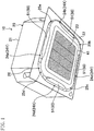
- an indoor unit (10) of a first embodiment is configured as a ceiling embedded indoor unit.
- the indoor unit (10) and an outdoor unit (not shown) together form an air-conditioning device.
- the indoor unit (10) and the outdoor unit are connected to each other by a communication pipe, thereby forming a refrigerant circuit in which a refrigerant circulates to perform a refrigeration cycle.
- the indoor unit (10) has a casing (20) (which corresponds to an indoor casing), an indoor fan (31), an indoor heat exchanger (32), a drain pan (33), a bell mouth (36), an airflow direction adjusting flap (51), a suction temperature sensor (81) (which corresponds to a temperature detector), and an indoor controller (90).
- the casing (20) is mounted in the ceiling (501) of an indoor space (500).
- the casing (20) is comprised of a casing body (21) and a decorative panel (22).
- the casing (20) houses the indoor fan (31), the indoor heat exchanger (32), the drain pan (33), and the bell mouth (36).
- the casing body (21) is mounted by being inserted in an opening in the ceiling (501) of the indoor space (500).
- the casing body (21) is in a substantially rectangular parallelepiped box-like shape with an open bottom end.
- the casing body (21) has approximately a flat top panel (21a) and a side panel (21b) projecting down from a peripheral portion of the top panel (21a).
- the indoor fan (31) is a centrifugal fan which blows air, sucked from below, radially outward.
- the indoor fan (31) is arranged at a central portion in the casing body (21).
- the indoor fan (31) is driven by an indoor fan motor (31a).
- the indoor fan motor (31a) is fixed to a central portion of the top panel (21a).
- the bell mouth (36) is located under the indoor fan (31).
- the bell mouth (36) is a member for guiding air which has flowed in the casing (20) to the indoor fan (31).
- the bell mouth (36) and the drain pan (33) divide the internal space of the casing (20) into a primary space (21c) on a suction side of the indoor fan (31) and a secondary space (21d) on an air-blowing side of the indoor fan (31).
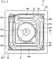
- the indoor heat exchanger (32) is a so-called cross-fin-and-tube heat exchanger. As illustrated in FIG. 2 , the indoor heat exchanger (32) is in the shape of a rectangular frame in plan view, and is disposed to surround the indoor fan (31). That is, the indoor heat exchanger (32) is disposed in the secondary space (21d). The indoor heat exchanger (32) allows the air passing therethrough from the inside to the outside to exchange heat with the refrigerant in the refrigerant circuit.
- the drain pan (33) is a member made of so-called Styrofoam. As illustrated in FIG. 3 , the drain pan (33) is disposed so as to close the lower end of the casing body (21). A water receiving groove (33b) is formed in the top surface of the drain pan (33) along the bottom end of the indoor heat exchanger (32). A bottom end portion of the indoor heat exchanger (32) is inserted in the water receiving groove (33b). The water receiving groove (33b) receives drain water generated in the indoor heat exchanger (32).
- the drain pan (33) is provided with four main outlet paths (34a to 34d) and four auxiliary outlet paths (35a to 35d). Air which has flowed through the indoor heat exchanger (32) flows through the main outlet paths (34a to 34d) and the auxiliary outlet paths (35a to 35d). These main and auxiliary outlet paths pass through the drain pan (33) in a vertical direction.
- Each of the main outlet paths (34a to 34d) is a through hole having an elongated rectangular cross section.
- the main outlet paths (34a to 34d) are disposed along the four sides of the casing body (21). Each side of the casing body (21) is provided with one main outlet path.
- Each of the auxiliary outlet paths (35a to 35d) is a through hole having a slightly-curved rectangular cross section.
- the auxiliary outlet paths (35a to 35d) are disposed at four corners of the casing body (21).
- Each corner of the casing body (21) is provided with one auxiliary outlet path. That is, the drain pan (33) is provided with the main outlet paths (34a to 34d) and the auxiliary outlet paths (35a to 35d) in an alternate manner along the periphery of the drain pan (33).
- the decorative panel (22) is a thick rectangular plate-like resin member.
- a lower portion of the decorative panel (22) has a square shape larger than the top panel (21a) of the casing body (21).
- the decorative panel (22) is disposed so as to cover a lower surface of the casing body (21).
- the lower surface of the decorative panel (22) serves as a lower surface of the casing (20), and is exposed to the indoor space (500).
- one inlet (23) in a square shape (which corresponds to an inlet opening) is formed at a central portion of the decorative panel (22).
- the inlet (23) passes through the decorative panel (22) in the vertical direction and communicates with the primary space (21c) in the casing (20). Air sucked into the casing (20) flows in the primary space (21c) through the inlet (23).
- the inlet (23) is provided with a grid-like suction grille (41).
- a suction filter (42) is provided above the suction grille (41).
- the decorative panel (22) is provided with an annular outlet (26) in an approximately rectangular shape which surrounds the inlet (23). As illustrated in FIG. 4 , the outlet (26) is divided into four main outlet openings (24a to 24d) (which correspond to outlet openings) and four auxiliary outlet openings (25a to 25d).
- Each of the main outlet openings (24a to 24d) has an elongated shape which corresponds to the cross section of each of the main outlet paths (34a to 34d).
- the main outlet openings (24a to 24d) are disposed along the four sides of the decorative panel (22). Each side of the decorative panel (22) is provided with one main outlet opening.
- the outlet openings (24a to 24d) of the decorative panel (22) correspond to the main outlet paths (34a to 34d) of the drain pan (33) on a one-on-one basis.
- Each of the main outlet openings (24a to 24d) communicates with a corresponding one of the main outlet paths (34a to 34d). That is, the first main outlet opening (24a) communicates with the first main outlet path (34a).
- the second main outlet opening (24b) communicates with the second main outlet path (34b).
- the third main outlet opening (24c) communicates with the third main outlet path (34c).
- the fourth main outlet opening (24d) communicates with the fourth main outlet path (34d).
- Each of the auxiliary outlet openings (25a to 25d) is in the shape of a quarter of a circle.
- the auxiliary outlet openings (25a to 25d) are disposed at the four corners of the decorative panel (22).
- Each corner of the decorative panel (22) is provided with one auxiliary outlet opening.
- the auxiliary outlet openings (25a to 25d) of the decorative panel (22) correspond to the auxiliary outlet paths (35a to 35d) of the drain pan (33) on a one-on-one basis.
- Each of the auxiliary outlet openings (25a to 25d) communicates with a corresponding one of the auxiliary outlet paths (35a to 35d). That is, the first auxiliary outlet opening (25a) communicates with the first auxiliary outlet path (35a).
- the second auxiliary outlet opening (25b) communicates with the second auxiliary outlet path (35b).
- the third auxiliary outlet opening (25c) communicates with the third auxiliary outlet path (35c).
- the fourth auxiliary outlet opening (25d) communicates with the fourth auxiliary outlet path (35d).
- each of the main outlet openings (24a to 24d) is provided with an airflow direction adjusting flap (51).
- the airflow direction adjusting flap (51) is a member which adjusts the direction of supply airflow (that is, the direction of air coming from the main outlet openings (24a to 24d)).
- the airflow direction adjusting flap (51) changes the direction of supply airflow upward and downward. That is, the airflow direction adjusting flap (51) changes the direction of supply airflow such that the angle between the direction of supply airflow and the horizontal direction changes.
- the airflow direction adjusting flap (51) has an elongated plate-like shape extending from one longitudinal end to the other longitudinal end of the main outlet opening (24a to 24d) formed in the decorative panel (22). As illustrated in FIG. 3 , the airflow direction adjusting flap (51) is supported on a support member (52) so as to be rotatable about its own central shaft (53) extending in the longitudinal direction thereof.
- the airflow direction adjusting flap (51) is curved such that its lateral cross section (a cross section taken in a direction orthogonal to the longitudinal direction) forms a convex shape in a direction away from the central shaft (53) of swing movement.
- a drive motor (54) is coupled to each airflow direction adjusting flap (51).
- the airflow direction adjusting flap (51) is activated by the drive motor (54) and rotates in a predetermined angle range about the central shaft (53).
- the airflow direction adjusting flap (51) can move to an airflow blocking position where the airflow direction adjusting flap (51) interrupts the flow of air passing through the main outlet opening (24a to 24d).
- the airflow direction adjusting flap (51) also functions as an airflow inhibition mechanism (50) which inhibits the supply airflow through the main outlet opening (24a to 24d).
- the suction temperature sensor (81) is disposed near the inlet (23).
- the suction temperature sensor (81) senses a suction temperature of air being sucked into the casing body (21) through the inlet (23).
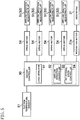
- the indoor controller (90) is comprised of a memory and a CPU, and controls the behavior of the indoor unit (10). As illustrated in FIG. 5 , the indoor controller (90) is connected to the suction temperature sensor (81), the drive motor (54) of each airflow direction adjusting flap (51), and the indoor fan motor (31a) of the indoor fan (31). With the CPU reading and executing various programs stored in the memory, the indoor controller (90) functions as a load detector (91) and a motor controller (92) (which corresponds to a controller).
- the motor controller (92) includes an airflow direction controller (93) which controls the drive motors (54) to control the direction of airflow coming from the main outlet openings (24a to 24d), and a rotational speed controller (94) which controls the indoor fan motor (31a).
- the load detector (91) detects a load of the indoor space (500) based on the suction temperature of air detected by the suction temperature sensor (81).
- the load of the indoor space (500) is detected by the load detector (91) particularly in the heating operation.
- the load detector (91) detects the load of the indoor space (500) based on a difference between a set temperature for the indoor space (500) in the heating operation and the result (i.e., the suction temperature) detected by the suction temperature sensor (81).
- the greater the difference is, the higher the load of the indoor space (500) detected in the heating operation is.
- the smaller the difference the lower the load of the indoor space (500) detected in the heating operation is.
- the load detector (91) detects that the indoor space (500) is in a high load state in which the load of the indoor space (500) is higher than the predetermined value.
- the load detector (91) detects that the indoor space (500) is in a low load state in which the load of the indoor space (500) is lower than the predetermined value.
- heating operation used in the present first embodiment includes supplying warm air into the indoor space (500) through the operation of a compressor (not shown) and the indoor fan (31), and also includes a state in which the operation of the compressor is temporarily stopped while keeping the operation of the indoor fan (31) (i.e., a circulation operation).
- the airflow direction controller (93) actuates each of the drive motors (54) to control the positions of the airflow direction adjusting flaps (51) independently from one another. Details about the control of the airflow direction controller (93) will be described in "-Control Operation of Airflow Direction Controller-.”
- the rotational speed controller (94) controls the rotational speed of the indoor fan (31) by control of the indoor fan motor (31a).
- the indoor fan (31) rotates during an operation of the indoor unit (10). Rotation of the indoor fan (31) causes the indoor air of the indoor space (500) to flow in the primary space (21c) of the casing (20) through the inlet (23). The air which has flowed in the primary space (21c) is drawn into the secondary space (21d) by the indoor fan (31).
- the air which has flowed in the secondary space (21d) is cooled or heated while passing through the indoor heat exchanger (32), and then flows separately into the four main outlet paths (34a to 34d) and four auxiliary outlet paths (35a to 35d).
- the air which has flowed in the main outlet paths (34a to 34d) is supplied to the indoor space (500) through the main outlet openings (24a to 24d).
- the air which has flowed in the auxiliary outlet paths (35a to 35d) is supplied to the indoor space (500) through the auxiliary outlet openings (25a to 25d).
- the indoor fan (31) generates the flow of air coming into the casing body (21) from the indoor space (500) through the inlet (23) and supplied back into the indoor space (500) through the outlet (26).
- the indoor heat exchanger (32) serves as an evaporator to cool the air while the air passes through the indoor heat exchanger (32).
- the indoor heat exchanger (32) serves as a condenser to heat the air while the air passes through the indoor heat exchanger (32).
- the airflow direction adjusting flap (51) rotates about the central shaft (53), thereby changing the direction of supply airflow.
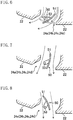
- the airflow direction adjusting flap (51) is movable between a horizontal airflow position illustrated in FIG. 6 and a downward airflow position illustrated in FIG. 7 .
- the airflow direction adjusting flap (51) may further rotate from the downward airflow position illustrated in FIG. 7 and move to an airflow blocking position illustrated in FIG. 8 .
- the airflow direction adjusting flap (51) When the airflow direction adjusting flap (51) is in the horizontal airflow position illustrated in FIG. 6 , the downward direction of the air coming from the main outlet path (34a to 34d) is changed to a lateral direction, and the supply airflow coming from the main outlet opening (24a to 24d) is horizontal.
- the direction of supply airflow through the main outlet opening (24a to 24d) (that is, the direction of air coming from the main outlet opening (24a to 24d)) is set to be about 25° from the horizontal direction. That is, strictly saying, the direction of the supply airflow is angled slightly downward from the horizontal direction, but substantially the same as the horizontal direction.
- the horizontal supply airflow allows the air coming from the main outlet opening (24a to 24d) to reach a wall (502) of the indoor space (500).
- the airflow direction adjusting flap (51) When the airflow direction adjusting flap (51) is in the downward airflow position illustrated in FIG. 7 , the downward direction of the air coming from the main outlet path (34a to 34d) is maintained substantially as it is, and the supply airflow coming from the main outlet opening (24a to 24d) is directed downward.
- the direction of the supply airflow is slightly angled from the vertical direction, that is, obliquely downward, away from the inlet (23).
- the airflow direction controller (93) controls the airflow direction adjusting flap (51) such that the airflow direction coming from the main outlet opening (24a to 24d) is horizontal (i.e., a horizontal airflow mode).
- Heating operation is performed when the outside air temperature is relatively low such as in winter.
- cold air may enter the indoor space (500) from near the walls of the indoor space (500).
- This phenomenon should be remarkable when the load of the indoor space (500) is high.
- the air coming from the main outlet opening (24a to 24d) is guided to flow in the horizontal direction by the airflow direction adjusting flap (51) when the load of the indoor space (500) is high in the heating operation.
- the relatively warm air coming from the main outlet opening (24a to 24d) reaches the wall (502) of the indoor space (500) and flows down along the wall (502).
- the wall (502) of the indoor space (500) is warmed by the air, and the temperature of the wall (502) of the indoor space (500) increases.
- the air which has reached the wall (502) blocks the cold air from entering the indoor space (500) from the wall (502). Consequently, the difference in temperature between a central portion and a peripheral portion (near the wall) of the indoor space (500) becomes small.
- the speed of the air coming from the main outlet opening (24a to 24d) is also controlled to be higher than when the load of the indoor space (500) is low (i.e., in a usual airflow mode) in the heating operation.
- Example methods for increasing the speed of the air include the following three methods (I) to (III):
- the airflow direction adjusting flap (51) of, for example, one main outlet opening (24a) is set to the airflow blocking position, and the airflow direction adjusting flaps (51) of the other main outlet openings (24b to 24d) are set to be horizontal (i.e., the horizontal airflow position). That is, according to the method (I), the total opening area of the main outlet openings (24a to 24d) is smaller than when the load of the indoor space (500) is low in the heating operation. In this case, substantially no air is supplied to the indoor space (500) from the main outlet opening (24a). However, air is supplied to the indoor space (500) from the other main outlet openings (24b to 24d) substantially in the horizontal direction at a higher speed than when the air is supplied from all the main outlet openings (24a to 24d).
- the rotational speed of the indoor fan (31) is increased.
- air is supplied at an increased speed substantially in the horizontal direction from the main outlet openings (24a to 24d) set to the horizontal airflow position.
- the method (III) employs both methods (I) and (II).
- air is supplied horizontally at a higher speed than in the methods (I) and (II) through the main outlet openings (24a to 24d) provided with the airflow direction adjusting flaps (51) taking the horizontal airflow position.
- the higher speed of the air that is increased by either one of the methods (I) to (III) contributes to reliably delivering the relatively warm air to the vicinity of the wall of the indoor space (500).
- the wall (502) of the indoor space (500) is warmed more reliably than when the speed of the air is not increased (that is, in the usual airflow mode), and the cold air is more reliably blocked from entering the indoor space (500) from the wall (502).
- a usual airflow operation which will be described in the "airflow rotation” below, may be performed when the load of the indoor space (500) is low (i.e., in the usual airflow mode).
- the airflow direction is horizontal due to the airflow direction adjusting flap (51) taking the horizontal airflow position.
- the speed of the air in the usual airflow mode may be controlled to be slower than in the horizontal airflow mode.
- the airflow direction controller (93) controls the position of the airflow direction adjusting flap (51) such that the indoor unit (10) can carry out a usual airflow operation, a first airflow operation, and a second airflow operation, which will be described later.
- the airflow direction controller (93) also controls the positions of the airflow direction adjusting flaps (51) of the main outlet openings (24a to 24d) such that the indoor unit (10) carries out an airflow rotation illustrated in FIG. 9 .
- a first-time usual airflow operation, a first airflow operation, a second-time usual airflow operation, and a second airflow operation are sequentially performed in a single cycle of the airflow rotation. That is, in a single cycle of the airflow rotation, the usual airflow operation is performed twice; the first airflow operation is performed once; and the second airflow operation is performed once.
- the rotational speed of the indoor fan (31) is kept substantially constant during the airflow rotation.
- An example case will be described below in which the method (I) is employed as a method for increasing the speed of the air during the airflow rotation.
- first opening (24X) first opening (24X)
- second opening (24Y) second opening (24Y)
- the airflow direction controller (93) sets the airflow direction adjusting flaps (51) of all the main outlet openings (24a to 24d) to the downward airflow position.
- the air is supplied downward from the four main outlet openings (24a to 24d) in the usual airflow operation in the heating operation.
- the airflow direction controller (93) sets the airflow direction adjusting flaps (51) of the two main outlet openings (24b, 24d) which form the first opening (24X) to the horizontal airflow position, and sets the airflow direction adjusting flaps (51) of the two main outlet openings (24a, 24c) which form the second opening (24Y) to the airflow blocking position.
- the air is supplied to the indoor space (500) from the second and fourth main outlet openings (24b) and (24d), and substantially no air is supplied to the indoor space (500) from the first and third main outlet openings (24a) and (24c).
- the speed of air coming from the second and fourth main outlet openings (24b) and (24d) is higher than the speed of air in the usual airflow operation.
- the air is supplied substantially horizontally from the second and fourth main outlet openings (24b) and (24d) at a higher flow speed than in the usual airflow operation.
- the airflow direction controller (93) sets the airflow direction adjusting flaps (51) of the two main outlet openings (24a, 24c) which form the second opening (24Y) to the horizontal airflow position, and sets the airflow direction adjusting flaps (51) of the two main outlet openings (24b, 24d) which form the first opening (24X) to the airflow blocking position.
- the air is supplied to the indoor space (500) from the first and third main outlet openings (24a) and (24c), and substantially no air is supplied to the indoor space (500) from the second and fourth main outlet openings (24b) and (24d).
- the speed of air coming from the first and third main outlet openings (24a) and (24c) is higher than the speed of air in the usual airflow operation.
- the conditioned air is supplied substantially horizontally from the first and third main outlet openings (24a) and (24c) at a higher flow speed than in the usual airflow operation.
- the air is supplied from the auxiliary outlet openings (25a to 25d) in all of the usual airflow operation, the first airflow operation, and the second airflow operation.
- the first-time usual airflow operation, the first airflow operation, the second-time airflow operation, and the second airflow operation have the same duration time (e.g., 120 seconds).
- Temperature distribution of the indoor space (500) in the heating operation will be described with reference to FIG. 10 .
- FIG. 10 illustrates results of simulation of the temperature distribution of the indoor space (500) during the heating operation of the indoor unit (10).
- FIG. 10 illustrates temperatures at a height of 60 cm above the floor surface of the indoor space (500) after 20 minutes from the start of the heating operation of the indoor unit (10). In FIG. 10 , higher temperatures are illustrated by a higher density of hatching.
- Such a room as follows is used as a simulation target room which has approximately a square floor surface and is furnished with two long desks (511) arranged parallel to each other with a partition (510) provided at a middle portion of each desk.
- the indoor unit (10) is located at approximately a center of the ceiling of the indoor space (500).
- the known indoor unit (610) sets the airflow direction adjusting flaps (51) of all the main outlet openings (24a to 24d) to the downward airflow position.
- the known indoor unit (610) supplies air which has been heated while passing through the indoor heat exchanger (32) substantially toward the floor surface from all the main outlet openings (24a to 24d).
- a central region of the indoor space (500) under the indoor unit (610) has a very high temperature. This may be because the warm conditioned air supplied downward from the indoor unit (610) remains in the central region of the indoor space (500) in between the two partitions (510).
- the temperature is not sufficiently increased in a peripheral region of the indoor space (500) apart from the indoor unit (610). This may be because the warm conditioned air supplied downward from the indoor unit (610) could not reach the region near the walls (502) over the partitions (510).
- the indoor unit (10) carries out the airflow rotation described above as an example application.
- the warm conditioned air supplied downward from the indoor unit (10) is supplied to a central region of the indoor space (500) in between the two partitions (510).
- the temperature increases in the central region of the indoor space (500) under the indoor unit (10).
- the usual airflow operation is performed intermittently, the temperature in the central region of the indoor space (500) does not increase excessively.
- the warm conditioned air is supplied from the indoor unit (10) at a higher flow speed than in the usual airflow operation in substantially the horizontal direction.
- the warm conditioned air supplied from the indoor unit (10) reaches the wall (502) of the indoor space (500) over the partitions (510). The temperature therefore increases in the peripheral region, too, of the indoor space (500) apart from the indoor unit (10).
- the warm conditioned air supplied from the indoor unit (10) reaches the wall (502) of the indoor space (500) and flows down along the wall (502).
- the wall (502) of the indoor space (500) is warmed by the conditioned air.
- the temperature of the wall (502) of the indoor space (500) increases accordingly.
- the temperature in the peripheral region of the indoor space (500) is less likely to drop due to the wall (502) warmed by the conditioned air.
- the airflow rotation in the heating operation greatly reduces the difference in the temperature between the central and peripheral regions of the indoor space (500), compared to the case where the known indoor unit (610) performs the heating operation.
- the airflow direction controller (93) sets the airflow direction adjusting flaps (51) of, for example, all the main outlet openings (24a to 24d) to alternately take the horizontal airflow position and the downward airflow position.
- airflow of the relatively cool air supplied from the main outlet openings (24a to 24d) changes according to the movement of each of the airflow direction adjusting flaps (51).
- the indoor unit (10) of the first embodiment supplies the air to the indoor space (500) in the horizontal direction when the load of the indoor space (500) in the heating operation is high (i.e., in the horizontal airflow mode).
- the relatively warm air can therefore reach the vicinity of the wall of the indoor space (500) from where cold air is likely to enter the indoor space (500).
- the relatively warm air blocks the cold air from coming into the indoor space (500) from near the wall. Entrance of cold air into the indoor space (500) from near the wall can be avoided in this manner. Consequently, the difference in temperature between a central portion and a peripheral portion (near the wall) of the indoor space (500) becomes small.
- the load of the indoor space (500) in the heating operation is determined by the difference between the set temperature and the suction temperature. This means that the load of the indoor space (500) in the heating operation can be determined by a simple method.
- the speed of the air coming from the main outlet opening (24a to 24d) is controlled to be higher than when the load of the indoor space (500) in the heating operation is low.
- the relatively warm air can reach the vicinity of the wall more easily. Entrance of cold air into the indoor space (500) from near the wall can be avoided more reliably.
- reducing the total opening area of the main outlet openings (24a to 24d) can be one of example methods for increasing the speed of air. According to this method, the speed of air can be easily increased.
- the method (I) can be carried out by the airflow direction adjusting flap (51) configured to be movable to the position where the flow of air is inhibited.
- This configuration allows the air to be supplied at a higher speed by reducing the total opening area of the main outlet openings (24a to 24d) without any other mechanism for inhibiting the flow of air provided independently of the airflow direction adjusting flap (51).
- increasing the rotational speed of the indoor fan (31) can be one of example methods for increasing the speed of air. According to this method, as well, the speed of air can be easily increased.
- the method (III) described above can also be employed as one of example methods for increasing the speed of air. According to the method (III), the flow of air can be increased more reliably.
- the indoor unit (10) is not limited to the ceiling embedded type.
- the indoor unit (10) may be of a ceiling suspended type or of a wall hanging type. Whatever the type of the indoor unit (10) is, the direction of air coming from the main outlet opening (24a to 24d) may be suitably determined so that the air reaches the vicinity of the wall of the indoor space (500) when the load of the indoor space (500) is high in the heating operation.
- the airflow direction controller (93) may control the airflow direction adjusting flap (51) such that the air coming from the main outlet opening (24a to 24d) is directed upward with respect to the horizontal direction (for example, such that the airflow direction adjusting flap (51) is angled 25° upward with respect to the horizontal direction) when the load of the indoor space (500) is high in the heating operation.
- the air coming from the main outlet opening (24a to 24d) may be supplied upward with respect to the horizontal direction using the Coanda effect.
- the angle of the airflow direction adjusting flap (51), while taking the horizontal airflow position, with respect to the horizontal direction may be finely adjusted as necessary, according to the distance from the location of the indoor unit (10) and the wall surface of the indoor space (500), so that the air coming from the main outlet opening (24a to 24d) can reach the vicinity of the wall of the indoor space (500).
- the distance from the location of the indoor unit (10) to the wall surface of the indoor space (500) may be input to the indoor controller (90) at the installation of the indoor unit (10) in the indoor space (500) by a worker who installs the indoor unit (10).
- a sensor for detecting the distance may be attached to the indoor unit (10) in advance.
- the load detector (91) may use, when detecting the load of the indoor space (500), a value corrected from the detection result of the suction temperature sensor (81) without using the detection result itself of the suction temperature sensor (81). Thus, the load detector (91) can detect an accurate load of the indoor space (500). This method is effective when the air coming from the main outlet opening (24a to 24d) and the auxiliary outlet opening (25a to 25d) does not circulate in the indoor space (500) and is directly drawn into the casing (20) through the inlet (23).
- the method for detecting the load of the indoor space (500) in the heating operation is not limited to the method using the set temperature and the detection result of the suction temperature sensor (81).
- the load detector (91) may detect the load of the indoor space (500) in the heating operation, using a mean value of the detection result of the suction temperature sensor (81) and a floor temperature of the indoor space (500). In this case, not the detection result itself of the suction temperature sensor (81), but a value corrected from the detected result of the suction temperature sensor (81) may be used.
- the load of the indoor space (500) in the heating operation may be determined from a wall surface load or a floor surface load of the indoor space (500).
- the load of the indoor space (500) in the heating operation may be detected at predetermined intervals, or may be detected when a user of the indoor space (500) sends an instruction via a remote controller.
- the load of the indoor space (500) in the heating operation may be detected by using a detection result, or a corrected value of the detection result, of a sensor provided separately in the indoor space (500) for detecting a room temperature, instead of the suction temperature sensor (81).
- Types of the sensor provided separately for detecting a room temperature may include not only a wired communication sensor, but also a wireless communication sensor.
- the number of main outlet openings (24a to 24d) is not limited to four. For example, one or two main outlet openings may be provided.
- the indoor unit (10) may have a shutter for closing the main outlet opening (24a to 24d) in addition to the airflow direction adjusting flap (51) as an airflow inhibition mechanism.
- the airflow inhibition mechanism is provided to correspond to each of the main outlet openings (24a to 24d).
- the airflow inhibition mechanism may be configured as an open/close shutter.
- the airflow rotation in the heating operation described above is not limited to such rotation as illustrated in FIG. 9 .
- the airflow rotation may be carried out by repeating the usual airflow operation, the first airflow operation, and the second airflow operation in a sequential manner.
- the first and second airflow operations of the airflow rotation may be carried out by supplying the air to the indoor space (500) from two main outlet openings (24a to 24d) arranged next to each other, and setting the airflow direction adjusting flaps (51) of the other two main outlet openings (24a to 24d) arranged next to each other to the airflow blocking position.
- the method (II) or (III) may be employed instead of the method (I), or any other method besides the methods (I) to (III) may be employed.
- the duration time of the operations in the airflow rotation does not have to be the same (e.g., 120 seconds), but may be different among the operations.
- the airflow direction adjusting flap (51) may close the corresponding main outlet opening (24a to 24d) completely, instead of taking the airflow blocking position in FIG. 8 .
- the first embodiment has described a case in which the load of the indoor space (500) is automatically detected by the load detector (91), and according to the detection result, the airflow direction adjusting flap (51) takes the horizontal airflow position.
- a second embodiment will describe a case in which the airflow direction adjusting flap (51) takes the horizontal airflow position when a person in the room sends such an instruction via a remote controller (201).
- an indoor unit (10) according to the second embodiment supplies air to the indoor space (500).
- the indoor unit (10) according to the second embodiment has a casing (20) (which corresponds to an indoor casing), an indoor fan (31), an indoor heat exchanger (32), a drain pan (33), a bell mouth (36), an airflow direction adjusting flap (51), an indoor controller (90), and a remote controller (201) (which corresponds to a receiver).
- the indoor controller (90) is connected to a drive motor (54) of each airflow direction adjusting flap (51), and an indoor fan motor (31a) of the indoor fan (31), and further to the remote controller (201).
- the indoor controller (90) functions as a motor controller (92) (which corresponds to a controller) having an airflow direction controller (93) and a rotational speed controller (94).
- the indoor unit (10) of the second embodiment does not have to be provided with the suction temperature sensor (81) of the first embodiment.
- the indoor controller (90) does not function as the load detector (91) of the first embodiment.
- the casing (20), the indoor fan (31), the indoor heat exchanger (32), the drain pan (33), the bell mouth (36), and the airflow direction adjusting flap (51) of the second embodiment are the same as, or similar to, those of the first embodiment.
- the casing (20) is comprised of a casing body (21) and a decorative panel (22), and is provided with a plurality of outlet openings (24a to 24d and 25a to 25d) and a single inlet (23).
- the indoor fan (31) generates the flow of air coming into the casing body (21) from the indoor space (500) through the inlet (23) and supplied back into the indoor space (500) through the outlet openings (24a to 24d and 25a to 25d).
- the indoor heat exchanger (32) allows the air drawn into the casing (20) to exchange heat with refrigerant.
- the drain pan (33) receives drain water generated in the indoor heat exchanger (32).
- the bell mouth (36) guides the air which has flowed in the casing (20) to the indoor fan (31).
- the airflow direction adjusting flap (51) is provided at a corresponding one of the main outlet openings (24a to 24d), and changes the direction of airflow coming from the main outlet opening (24a to 24d) in the vertical direction.
- the remote controller (201) is attached, for example, to the wall (502) of the indoor space (500), and is connected to the indoor controller (90) such that wired or wireless communication can be established with the indoor controller (90).
- the remote controller (201) receives an instruction from a person in the room. That is, the person in the room can adjust various settings of the air-conditioning device and operating instructions via the remote controller (201).
- the remote controller (201) which has received a setting instruction or an operating instruction sends the instruction to the indoor controller (90).
- the indoor unit (10) of the second embodiment has a horizontal airflow mode in which air is supplied intentionally in the horizontal direction.
- the remote controller (201) has a horizontal airflow mode selecting button for receiving an external instruction selecting the horizontal airflow mode. When the horizontal airflow mode is selected by the button, the remote controller (201) informs the the indoor controller (90) of the selection of the horizontal airflow mode.
- the horizontal airflow mode may be selected by the button by a person in the room when the person has instructed the start of a heating operation via the remote controller (201) but still feels that the temperature is lower near the wall of the indoor space (500) than a central portion of the indoor space (500). That is, the person in the room may select the horizontal airflow mode by the button when the person himself/herself feels that the load of the indoor space (500) is high.
- the airflow direction controller (93) of the second embodiment controls each of the airflow direction adjusting flaps (51) such that the airflow direction coming from the main outlet openings (24a to 24d) is horizontal. That is, the airflow direction controller (93) sets the airflow direction adjusting flaps (51) to the horizontal airflow position, so that the airflow direction coming from the main outlet openings (24a to 24d) be horizontal, when the person in the room feels that the load of the indoor space (500) is high.
- the motor controller (92) controls the speed of air coming from the main outlet openings (24a to 24d) to be higher than when the remote controller (201) does not receive the selection of the horizontal airflow mode (i.e., when the horizontal airflow mode is not selected, that is, the indoor unit is in the usual airflow mode).
- Example methods for increasing the speed of the air include the following three methods (I) to (III):
- the relatively warm air coming from the main outlet opening (24a to 24d) reaches the vicinity of the wall (502) of the indoor space (500) and flows down along the wall (502).
- the wall (502) of the indoor space (500) is reliably warmed by the air, and the temperature of the wall (502) of the indoor space (500) increases.
- the air which has reached the wall (502) blocks the cold air from entering the indoor space (500) from the wall (502). Consequently, the difference in temperature between a central portion and a peripheral portion (near the wall) of the indoor space (500) becomes small.
- the air may flows downward in the usual airflow mode.
- the airflow direction is horizontal, but the speed of the air in the usual airflow mode may be controlled to be slower than in the horizontal airflow mode.
- Example applications of the horizontal airflow mode in the heating operation of the second embodiment include the airflow rotation described in the first embodiment. That is, when the horizontal airflow mode is selected in the heating operation, the airflow rotation described in the first embodiment may be performed. Detailed description of the airflow rotation and the description of temperature distribution in the indoor space (500) will be omitted.
- Airflow in cooling operation is the same as, or similar to, that of the first embodiment. The explanation thereof will thus be omitted.
- the indoor unit (10) of the second embodiment supplies the air to the indoor space (500) in the horizontal direction when the remote controller (201) receives the horizontal airflow mode in the heating operation.
- the horizontal airflow mode is selected by the person in the room when the person himself/herself feels that the indoor space (500) is in the so-called high load state.
- the relatively warm air can therefore reach the vicinity of the wall of the indoor space (500) from where cold air is likely to enter the indoor space (500).
- the relatively warm air blocks the cold air from coming into the indoor space (500) from near the wall. Entrance of cold air into the indoor space (500) from near the wall can therefore be avoided. Consequently, the difference in temperature between a central portion and a peripheral portion (near the wall) of the indoor space (500) becomes small.
- the speed of air coming from the main outlet opening (24a to 24d) is controlled to be higher than when the remote controller (201) does not receive the horizontal airflow mode (e.g., the indoor unit is in the usual airflow mode).
- the relatively warm air can reach the vicinity of the wall more easily. Entrance of cold air into the indoor space (500) from near the wall can be avoided more reliably.
- reducing the total opening area of the main outlet openings (24a to 24d) can be one of example methods for increasing the speed of air. According to this method, the speed of air can be easily increased.
- the method (I) can be carried out by the airflow direction adjusting flap (51) configured to be movable to the position where the flow of air is inhibited.
- This configuration allows the air to be supplied at a higher speed by reducing the total opening area of the main outlet openings (24a to 24d) without any other airflow inhibition mechanism (50) for inhibiting the flow of air provided independently of the airflow direction adjusting flap (51).
- increasing the rotational speed of the indoor fan (31) can be one of example methods for increasing the speed of air. According to this method, as well, the speed of air can be easily increased.
- the method (III) described above can be employed as one of example methods for increasing the speed of air. According to the method (III), the flow of air can be increased more reliably.
- the indoor unit (10) is not limited to the ceiling embedded type.
- the indoor unit (10) may be of a ceiling suspended type or of a wall hanging type. Whatever the type of the indoor unit (10) is, the direction of air coming from the main outlet opening (24a to 24d) may be suitably determined so that the air reaches the vicinity of the wall of the indoor space (500) when the horizontal airflow mode is selected in the heating operation.
- the airflow direction controller (93) may control the airflow direction adjusting flap (51) such that the air coming from the main outlet opening (24a to 24d) is directed upward with respect to the horizontal direction (for example, such that the airflow direction adjusting flap (51) is angled 25° upward with respect to the horizontal direction) when the horizontal airflow mode is selected in the heating operation.
- the air coming from the main outlet opening (24a to 24d) may be supplied upward with respect to the horizontal direction using the Coanda effect.
- the angle of the airflow direction adjusting flap (51), while taking the horizontal airflow position, with respect to the horizontal direction may be finely adjusted as necessary, according to the distance from the location of the indoor unit (10) and the wall surface of the indoor space (500), so that the air coming from the main outlet opening (24a to 24d) can reach the vicinity of the wall of the indoor space (500).
- the distance from the location of the indoor unit (10) to the wall surface of the indoor space (500) may be input to the indoor controller (90) at the installation of the indoor unit (10) in the indoor space (500) by a worker who installs the indoor unit (10).
- a sensor for detecting the distance may be attached to the indoor unit (10) in advance.
- the number of main outlet openings (24a to 24d) is not limited to four. For example, one or two main outlet openings may be provided.
- the indoor unit (10) may have a shutter for closing the main outlet opening (24a to 24d) in addition to the airflow direction adjusting flaps (51) as an airflow inhibition mechanism.
- the airflow inhibition mechanism is provided to correspond to each of the main outlet openings (24a to 24d).
- the airflow inhibition mechanism may be configured as an open/close shutter.
- the indoor unit (10) may be configured as a combination of an aspect of the first embodiment, that is, automatically detecting the load of the indoor space and taking the horizontal airflow position, and an aspect of the second embodiment, that is, taking the horizontal airflow position in accordance with an instruction from a person in the room.
- the indoor unit (10) may have an automatic detection mode detecting automatically the load of the indoor space (500) and taking the horizontal airflow mode, and a manual mode not detecting automatically the load of the indoor space (500) and taking the horizontal airflow mode in accordance with the instruction from the person in the room.
- the indoor unit (10) may be configured to be switchable between the automatic detection mode and the manual mode by the person in the room via the remote controller (201).
- the indoor unit (10) can employ the aspect of the first embodiment when the automatic detection mode is selected, and employ the aspect of the second embodiment when the manual mode is selected.
- the airflow direction adjusting flap (51) may close the corresponding main outlet opening (24a to 24d) completely, instead of taking the airflow blocking position in FIG. 8 .
- the present invention is useful as an indoor unit of an air-conditioning device which supplies air to an indoor space.
Landscapes
- Engineering & Computer Science (AREA)
- Chemical & Material Sciences (AREA)
- Combustion & Propulsion (AREA)
- Mechanical Engineering (AREA)
- General Engineering & Computer Science (AREA)
- Physics & Mathematics (AREA)
- Fluid Mechanics (AREA)
- Air Conditioning Control Device (AREA)
- Air-Flow Control Members (AREA)
- Air Filters, Heat-Exchange Apparatuses, And Housings Of Air-Conditioning Units (AREA)
Applications Claiming Priority (2)
| Application Number | Priority Date | Filing Date | Title |
|---|---|---|---|
| JP2015191716A JP6135734B2 (ja) | 2015-09-29 | 2015-09-29 | 空気調和装置の室内ユニット |
| PCT/JP2016/003898 WO2017056386A1 (ja) | 2015-09-29 | 2016-08-26 | 空気調和装置の室内ユニット |
Publications (3)
| Publication Number | Publication Date |
|---|---|
| EP3346202A1 true EP3346202A1 (de) | 2018-07-11 |
| EP3346202A4 EP3346202A4 (de) | 2019-05-15 |
| EP3346202B1 EP3346202B1 (de) | 2020-11-18 |
Family
ID=58422868
Family Applications (1)
| Application Number | Title | Priority Date | Filing Date |
|---|---|---|---|
| EP16850569.1A Active EP3346202B1 (de) | 2015-09-29 | 2016-08-26 | Klimaanlagenvorrichtung und innenraumeinheit |
Country Status (7)
| Country | Link |
|---|---|
| US (1) | US10655885B2 (de) |
| EP (1) | EP3346202B1 (de) |
| JP (1) | JP6135734B2 (de) |
| CN (1) | CN108139108B (de) |
| AU (1) | AU2016330563B2 (de) |
| ES (1) | ES2835062T3 (de) |
| WO (1) | WO2017056386A1 (de) |
Families Citing this family (8)
| Publication number | Priority date | Publication date | Assignee | Title |
|---|---|---|---|---|
| JP6213539B2 (ja) * | 2015-09-29 | 2017-10-18 | ダイキン工業株式会社 | 空気調和装置の室内ユニット |
| JP6269700B2 (ja) * | 2016-02-22 | 2018-01-31 | ダイキン工業株式会社 | 受信器およびこれを備えた空気調和装置 |
| CN107166696A (zh) * | 2017-06-09 | 2017-09-15 | 青岛海尔空调器有限总公司 | 空调及用于空调的控制方法 |
| CN110121621B (zh) * | 2017-12-05 | 2021-04-27 | 日立江森自控空调有限公司 | 空调机的室内机 |
| CN110779089B (zh) * | 2018-07-12 | 2021-11-12 | 青岛海尔空调器有限总公司 | 空调器的送风控制方法与空调器 |
| CN108758836A (zh) * | 2018-08-24 | 2018-11-06 | 珠海格力电器股份有限公司 | 空调器室内机及具有其的空调器 |
| EP4269884B1 (de) | 2021-07-12 | 2026-02-04 | Samsung Electronics Co., Ltd. | Klimaanlage |
| CN115183357B (zh) * | 2022-07-12 | 2024-02-23 | 艾欧史密斯(中国)热水器有限公司 | 室内空气净化系统及其控制方法、控制装置及存储介质 |
Family Cites Families (29)
| Publication number | Priority date | Publication date | Assignee | Title |
|---|---|---|---|---|
| JP2594318B2 (ja) | 1988-05-30 | 1997-03-26 | 松下冷機株式会社 | 天井埋込型空気調和機 |
| JPH0650595A (ja) * | 1992-07-29 | 1994-02-22 | Toshiba Corp | 空気調和装置 |
| JPH10103739A (ja) | 1996-09-27 | 1998-04-21 | Toshiba Corp | 空気調和機 |
| JPH1163627A (ja) * | 1997-08-20 | 1999-03-05 | Funai Electric Co Ltd | 空気調和機のフラップ制御装置及び方法並びにフラップ制御プログラムを記録した記録媒体 |
| JP2980093B2 (ja) * | 1998-03-02 | 1999-11-22 | ダイキン工業株式会社 | 空気調和機のファン制御装置 |
| JP3807305B2 (ja) * | 2001-12-28 | 2006-08-09 | ダイキン工業株式会社 | 空気調和機 |
| US6736326B2 (en) * | 2002-02-01 | 2004-05-18 | Acutherm L.P. | Thermally powered VAV diffuser and control assembly |
| JP2005024154A (ja) | 2003-07-01 | 2005-01-27 | Matsushita Electric Ind Co Ltd | 空気調和機 |
| JP5063509B2 (ja) * | 2008-06-30 | 2012-10-31 | 三菱電機株式会社 | 空気調和機 |
| AU2010299201B2 (en) * | 2009-09-28 | 2013-07-25 | Daikin Industries, Ltd. | Control device |
| JP2011069594A (ja) * | 2009-09-28 | 2011-04-07 | Daikin Industries Ltd | 制御装置 |
| JP4952775B2 (ja) * | 2009-11-05 | 2012-06-13 | ダイキン工業株式会社 | 空気調和装置の室内機 |
| JP5446779B2 (ja) * | 2009-11-25 | 2014-03-19 | ダイキン工業株式会社 | 空調制御システム |
| JP5250011B2 (ja) * | 2010-10-26 | 2013-07-31 | 三菱電機株式会社 | 空気調和機 |
| JP2012184868A (ja) * | 2011-03-04 | 2012-09-27 | Hitachi Appliances Inc | 空調システム |
| CN103477155B (zh) * | 2011-12-06 | 2016-08-31 | 松下电器产业株式会社 | 空调机 |
| JP6056297B2 (ja) * | 2012-09-13 | 2017-01-11 | ダイキン工業株式会社 | 空調室内機 |
| JP5754429B2 (ja) * | 2012-09-13 | 2015-07-29 | ダイキン工業株式会社 | 空調室内機 |
| JP5408317B1 (ja) * | 2012-09-13 | 2014-02-05 | ダイキン工業株式会社 | 空調室内機 |
| JP5678953B2 (ja) * | 2012-12-28 | 2015-03-04 | 株式会社富士通ゼネラル | 空気調和機および制御回路 |
| JP5725114B2 (ja) * | 2013-09-24 | 2015-05-27 | ダイキン工業株式会社 | 空調システム |
| KR20150041340A (ko) * | 2013-10-08 | 2015-04-16 | 엘지전자 주식회사 | 카세트형 공기조화기의 실내기 |
| JP5987882B2 (ja) * | 2014-09-30 | 2016-09-07 | ダイキン工業株式会社 | 空気調和装置の室内ユニット |
| JP6734624B2 (ja) * | 2014-09-30 | 2020-08-05 | ダイキン工業株式会社 | 空気調和装置の室内ユニット |
| JP6229741B2 (ja) * | 2015-09-29 | 2017-11-15 | ダイキン工業株式会社 | 空気調和装置の室内ユニット |
| JP6213539B2 (ja) * | 2015-09-29 | 2017-10-18 | ダイキン工業株式会社 | 空気調和装置の室内ユニット |
| JP6222211B2 (ja) * | 2015-12-18 | 2017-11-01 | ダイキン工業株式会社 | 空気調和装置 |
| CN205403096U (zh) * | 2016-02-19 | 2016-07-27 | 珠海格力电器股份有限公司 | 空调设备出风结构及空调设备 |
| JP6625210B2 (ja) * | 2016-05-27 | 2019-12-25 | 三菱電機株式会社 | 天井埋込形空気調和装置 |
-
2015
- 2015-09-29 JP JP2015191716A patent/JP6135734B2/ja active Active
-
2016
- 2016-08-26 EP EP16850569.1A patent/EP3346202B1/de active Active
- 2016-08-26 ES ES16850569T patent/ES2835062T3/es active Active
- 2016-08-26 WO PCT/JP2016/003898 patent/WO2017056386A1/ja not_active Ceased
- 2016-08-26 AU AU2016330563A patent/AU2016330563B2/en active Active
- 2016-08-26 US US15/758,438 patent/US10655885B2/en active Active
- 2016-08-26 CN CN201680056603.0A patent/CN108139108B/zh active Active
Also Published As
| Publication number | Publication date |
|---|---|
| US20180252429A1 (en) | 2018-09-06 |
| WO2017056386A1 (ja) | 2017-04-06 |
| EP3346202A4 (de) | 2019-05-15 |
| JP6135734B2 (ja) | 2017-05-31 |
| ES2835062T3 (es) | 2021-06-21 |
| US10655885B2 (en) | 2020-05-19 |
| CN108139108A (zh) | 2018-06-08 |
| CN108139108B (zh) | 2019-03-19 |
| EP3346202B1 (de) | 2020-11-18 |
| JP2017067346A (ja) | 2017-04-06 |
| AU2016330563B2 (en) | 2018-07-05 |
| AU2016330563A1 (en) | 2018-04-19 |
Similar Documents
| Publication | Publication Date | Title |
|---|---|---|
| EP3346202B1 (de) | Klimaanlagenvorrichtung und innenraumeinheit | |
| EP3372913B1 (de) | Klimaanlage | |
| EP3406980B1 (de) | Klimatisierungssystem | |
| EP3358265B1 (de) | Innenraumeinheit einer klimaanlage | |
| EP3508797A1 (de) | Innenraumeinheit | |
| EP3203160B1 (de) | Innenraumeinheit für eine klimaanlagenvorrichtung | |
| EP3406979B1 (de) | Klimatisierungssystem | |
| KR102575089B1 (ko) | 공기조화 시스템 | |
| KR20180035291A (ko) | 공기조화 시스템 | |
| WO2017056365A1 (ja) | 空気調和装置の室内ユニット | |
| BR112018011599B1 (pt) | Aparelho de ar condicionado | |
| JP2017180877A (ja) | 空調システム |
Legal Events
| Date | Code | Title | Description |
|---|---|---|---|
| STAA | Information on the status of an ep patent application or granted ep patent |
Free format text: STATUS: THE INTERNATIONAL PUBLICATION HAS BEEN MADE |
|
| PUAI | Public reference made under article 153(3) epc to a published international application that has entered the european phase |
Free format text: ORIGINAL CODE: 0009012 |
|
| STAA | Information on the status of an ep patent application or granted ep patent |
Free format text: STATUS: REQUEST FOR EXAMINATION WAS MADE |
|
| 17P | Request for examination filed |
Effective date: 20180403 |
|
| AK | Designated contracting states |
Kind code of ref document: A1 Designated state(s): AL AT BE BG CH CY CZ DE DK EE ES FI FR GB GR HR HU IE IS IT LI LT LU LV MC MK MT NL NO PL PT RO RS SE SI SK SM TR |
|
| AX | Request for extension of the european patent |
Extension state: BA ME |
|
| DAV | Request for validation of the european patent (deleted) | ||
| DAX | Request for extension of the european patent (deleted) | ||
| RIC1 | Information provided on ipc code assigned before grant |
Ipc: F24F 11/02 20060101AFI20170418BHEP |
|
| REG | Reference to a national code |
Ref country code: DE Ref legal event code: R079 Ref document number: 602016048299 Country of ref document: DE Free format text: PREVIOUS MAIN CLASS: F24F0011020000 Ipc: F24F0011770000 |
|
| A4 | Supplementary search report drawn up and despatched |
Effective date: 20190411 |
|
| RIC1 | Information provided on ipc code assigned before grant |
Ipc: F24F 11/79 20180101ALI20190405BHEP Ipc: F24F 140/50 20180101ALI20190405BHEP Ipc: F24F 1/0014 20190101ALI20190405BHEP Ipc: F24F 1/0047 20190101ALI20190405BHEP Ipc: F24F 11/77 20180101AFI20190405BHEP Ipc: F24F 110/10 20180101ALI20190405BHEP |
|
| STAA | Information on the status of an ep patent application or granted ep patent |
Free format text: STATUS: EXAMINATION IS IN PROGRESS |
|
| 17Q | First examination report despatched |
Effective date: 20191218 |
|
| GRAP | Despatch of communication of intention to grant a patent |
Free format text: ORIGINAL CODE: EPIDOSNIGR1 |
|
| STAA | Information on the status of an ep patent application or granted ep patent |
Free format text: STATUS: GRANT OF PATENT IS INTENDED |
|
| INTG | Intention to grant announced |
Effective date: 20200714 |
|
| GRAS | Grant fee paid |
Free format text: ORIGINAL CODE: EPIDOSNIGR3 |
|
| GRAA | (expected) grant |
Free format text: ORIGINAL CODE: 0009210 |
|
| STAA | Information on the status of an ep patent application or granted ep patent |
Free format text: STATUS: THE PATENT HAS BEEN GRANTED |
|
| AK | Designated contracting states |
Kind code of ref document: B1 Designated state(s): AL AT BE BG CH CY CZ DE DK EE ES FI FR GB GR HR HU IE IS IT LI LT LU LV MC MK MT NL NO PL PT RO RS SE SI SK SM TR |
|
| REG | Reference to a national code |
Ref country code: GB Ref legal event code: FG4D |
|
| REG | Reference to a national code |
Ref country code: CH Ref legal event code: EP |
|
| REG | Reference to a national code |
Ref country code: IE Ref legal event code: FG4D |
|
| REG | Reference to a national code |
Ref country code: DE Ref legal event code: R096 Ref document number: 602016048299 Country of ref document: DE |
|
| REG | Reference to a national code |
Ref country code: AT Ref legal event code: REF Ref document number: 1336198 Country of ref document: AT Kind code of ref document: T Effective date: 20201215 |
|
| REG | Reference to a national code |
Ref country code: AT Ref legal event code: MK05 Ref document number: 1336198 Country of ref document: AT Kind code of ref document: T Effective date: 20201118 |
|
| REG | Reference to a national code |
Ref country code: NL Ref legal event code: MP Effective date: 20201118 |
|
| PG25 | Lapsed in a contracting state [announced via postgrant information from national office to epo] |
Ref country code: NO Free format text: LAPSE BECAUSE OF FAILURE TO SUBMIT A TRANSLATION OF THE DESCRIPTION OR TO PAY THE FEE WITHIN THE PRESCRIBED TIME-LIMIT Effective date: 20210218 Ref country code: PT Free format text: LAPSE BECAUSE OF FAILURE TO SUBMIT A TRANSLATION OF THE DESCRIPTION OR TO PAY THE FEE WITHIN THE PRESCRIBED TIME-LIMIT Effective date: 20210318 Ref country code: RS Free format text: LAPSE BECAUSE OF FAILURE TO SUBMIT A TRANSLATION OF THE DESCRIPTION OR TO PAY THE FEE WITHIN THE PRESCRIBED TIME-LIMIT Effective date: 20201118 Ref country code: FI Free format text: LAPSE BECAUSE OF FAILURE TO SUBMIT A TRANSLATION OF THE DESCRIPTION OR TO PAY THE FEE WITHIN THE PRESCRIBED TIME-LIMIT Effective date: 20201118 Ref country code: GR Free format text: LAPSE BECAUSE OF FAILURE TO SUBMIT A TRANSLATION OF THE DESCRIPTION OR TO PAY THE FEE WITHIN THE PRESCRIBED TIME-LIMIT Effective date: 20210219 |
|
| PG25 | Lapsed in a contracting state [announced via postgrant information from national office to epo] |
Ref country code: AT Free format text: LAPSE BECAUSE OF FAILURE TO SUBMIT A TRANSLATION OF THE DESCRIPTION OR TO PAY THE FEE WITHIN THE PRESCRIBED TIME-LIMIT Effective date: 20201118 Ref country code: IS Free format text: LAPSE BECAUSE OF FAILURE TO SUBMIT A TRANSLATION OF THE DESCRIPTION OR TO PAY THE FEE WITHIN THE PRESCRIBED TIME-LIMIT Effective date: 20210318 Ref country code: LV Free format text: LAPSE BECAUSE OF FAILURE TO SUBMIT A TRANSLATION OF THE DESCRIPTION OR TO PAY THE FEE WITHIN THE PRESCRIBED TIME-LIMIT Effective date: 20201118 Ref country code: PL Free format text: LAPSE BECAUSE OF FAILURE TO SUBMIT A TRANSLATION OF THE DESCRIPTION OR TO PAY THE FEE WITHIN THE PRESCRIBED TIME-LIMIT Effective date: 20201118 Ref country code: BG Free format text: LAPSE BECAUSE OF FAILURE TO SUBMIT A TRANSLATION OF THE DESCRIPTION OR TO PAY THE FEE WITHIN THE PRESCRIBED TIME-LIMIT Effective date: 20210218 Ref country code: SE Free format text: LAPSE BECAUSE OF FAILURE TO SUBMIT A TRANSLATION OF THE DESCRIPTION OR TO PAY THE FEE WITHIN THE PRESCRIBED TIME-LIMIT Effective date: 20201118 |
|
| REG | Reference to a national code |
Ref country code: ES Ref legal event code: FG2A Ref document number: 2835062 Country of ref document: ES Kind code of ref document: T3 Effective date: 20210621 |
|
| REG | Reference to a national code |
Ref country code: LT Ref legal event code: MG9D |
|
| PG25 | Lapsed in a contracting state [announced via postgrant information from national office to epo] |
Ref country code: HR Free format text: LAPSE BECAUSE OF FAILURE TO SUBMIT A TRANSLATION OF THE DESCRIPTION OR TO PAY THE FEE WITHIN THE PRESCRIBED TIME-LIMIT Effective date: 20201118 |
|
| PG25 | Lapsed in a contracting state [announced via postgrant information from national office to epo] |
Ref country code: SK Free format text: LAPSE BECAUSE OF FAILURE TO SUBMIT A TRANSLATION OF THE DESCRIPTION OR TO PAY THE FEE WITHIN THE PRESCRIBED TIME-LIMIT Effective date: 20201118 Ref country code: RO Free format text: LAPSE BECAUSE OF FAILURE TO SUBMIT A TRANSLATION OF THE DESCRIPTION OR TO PAY THE FEE WITHIN THE PRESCRIBED TIME-LIMIT Effective date: 20201118 Ref country code: LT Free format text: LAPSE BECAUSE OF FAILURE TO SUBMIT A TRANSLATION OF THE DESCRIPTION OR TO PAY THE FEE WITHIN THE PRESCRIBED TIME-LIMIT Effective date: 20201118 Ref country code: SM Free format text: LAPSE BECAUSE OF FAILURE TO SUBMIT A TRANSLATION OF THE DESCRIPTION OR TO PAY THE FEE WITHIN THE PRESCRIBED TIME-LIMIT Effective date: 20201118 Ref country code: EE Free format text: LAPSE BECAUSE OF FAILURE TO SUBMIT A TRANSLATION OF THE DESCRIPTION OR TO PAY THE FEE WITHIN THE PRESCRIBED TIME-LIMIT Effective date: 20201118 Ref country code: CZ Free format text: LAPSE BECAUSE OF FAILURE TO SUBMIT A TRANSLATION OF THE DESCRIPTION OR TO PAY THE FEE WITHIN THE PRESCRIBED TIME-LIMIT Effective date: 20201118 |
|
| REG | Reference to a national code |
Ref country code: DE Ref legal event code: R097 Ref document number: 602016048299 Country of ref document: DE |
|
| PG25 | Lapsed in a contracting state [announced via postgrant information from national office to epo] |
Ref country code: DK Free format text: LAPSE BECAUSE OF FAILURE TO SUBMIT A TRANSLATION OF THE DESCRIPTION OR TO PAY THE FEE WITHIN THE PRESCRIBED TIME-LIMIT Effective date: 20201118 |
|
| PLBE | No opposition filed within time limit |
Free format text: ORIGINAL CODE: 0009261 |
|
| STAA | Information on the status of an ep patent application or granted ep patent |
Free format text: STATUS: NO OPPOSITION FILED WITHIN TIME LIMIT |
|
| 26N | No opposition filed |
Effective date: 20210819 |
|
| PG25 | Lapsed in a contracting state [announced via postgrant information from national office to epo] |
Ref country code: AL Free format text: LAPSE BECAUSE OF FAILURE TO SUBMIT A TRANSLATION OF THE DESCRIPTION OR TO PAY THE FEE WITHIN THE PRESCRIBED TIME-LIMIT Effective date: 20201118 Ref country code: NL Free format text: LAPSE BECAUSE OF FAILURE TO SUBMIT A TRANSLATION OF THE DESCRIPTION OR TO PAY THE FEE WITHIN THE PRESCRIBED TIME-LIMIT Effective date: 20201118 |
|
| PG25 | Lapsed in a contracting state [announced via postgrant information from national office to epo] |
Ref country code: SI Free format text: LAPSE BECAUSE OF FAILURE TO SUBMIT A TRANSLATION OF THE DESCRIPTION OR TO PAY THE FEE WITHIN THE PRESCRIBED TIME-LIMIT Effective date: 20201118 |
|
| REG | Reference to a national code |
Ref country code: CH Ref legal event code: PL |
|
| PG25 | Lapsed in a contracting state [announced via postgrant information from national office to epo] |
Ref country code: MC Free format text: LAPSE BECAUSE OF FAILURE TO SUBMIT A TRANSLATION OF THE DESCRIPTION OR TO PAY THE FEE WITHIN THE PRESCRIBED TIME-LIMIT Effective date: 20201118 |
|
| REG | Reference to a national code |
Ref country code: BE Ref legal event code: MM Effective date: 20210831 |
|
| PG25 | Lapsed in a contracting state [announced via postgrant information from national office to epo] |
Ref country code: LI Free format text: LAPSE BECAUSE OF NON-PAYMENT OF DUE FEES Effective date: 20210831 Ref country code: CH Free format text: LAPSE BECAUSE OF NON-PAYMENT OF DUE FEES Effective date: 20210831 |
|
| PG25 | Lapsed in a contracting state [announced via postgrant information from national office to epo] |
Ref country code: IS Free format text: LAPSE BECAUSE OF FAILURE TO SUBMIT A TRANSLATION OF THE DESCRIPTION OR TO PAY THE FEE WITHIN THE PRESCRIBED TIME-LIMIT Effective date: 20210318 Ref country code: LU Free format text: LAPSE BECAUSE OF NON-PAYMENT OF DUE FEES Effective date: 20210826 |
|
| PG25 | Lapsed in a contracting state [announced via postgrant information from national office to epo] |
Ref country code: IE Free format text: LAPSE BECAUSE OF NON-PAYMENT OF DUE FEES Effective date: 20210826 Ref country code: BE Free format text: LAPSE BECAUSE OF NON-PAYMENT OF DUE FEES Effective date: 20210831 |
|
| PG25 | Lapsed in a contracting state [announced via postgrant information from national office to epo] |
Ref country code: HU Free format text: LAPSE BECAUSE OF FAILURE TO SUBMIT A TRANSLATION OF THE DESCRIPTION OR TO PAY THE FEE WITHIN THE PRESCRIBED TIME-LIMIT; INVALID AB INITIO Effective date: 20160826 |
|
| PG25 | Lapsed in a contracting state [announced via postgrant information from national office to epo] |
Ref country code: CY Free format text: LAPSE BECAUSE OF FAILURE TO SUBMIT A TRANSLATION OF THE DESCRIPTION OR TO PAY THE FEE WITHIN THE PRESCRIBED TIME-LIMIT Effective date: 20201118 |
|
| P01 | Opt-out of the competence of the unified patent court (upc) registered |
Effective date: 20230525 |
|
| PG25 | Lapsed in a contracting state [announced via postgrant information from national office to epo] |
Ref country code: MK Free format text: LAPSE BECAUSE OF FAILURE TO SUBMIT A TRANSLATION OF THE DESCRIPTION OR TO PAY THE FEE WITHIN THE PRESCRIBED TIME-LIMIT Effective date: 20201118 |
|
| PG25 | Lapsed in a contracting state [announced via postgrant information from national office to epo] |
Ref country code: MT Free format text: LAPSE BECAUSE OF FAILURE TO SUBMIT A TRANSLATION OF THE DESCRIPTION OR TO PAY THE FEE WITHIN THE PRESCRIBED TIME-LIMIT Effective date: 20201118 |
|
| PGFP | Annual fee paid to national office [announced via postgrant information from national office to epo] |
Ref country code: TR Payment date: 20240731 Year of fee payment: 9 |
|
| PGFP | Annual fee paid to national office [announced via postgrant information from national office to epo] |
Ref country code: ES Payment date: 20250901 Year of fee payment: 10 |
|
| PGFP | Annual fee paid to national office [announced via postgrant information from national office to epo] |
Ref country code: DE Payment date: 20250702 Year of fee payment: 10 |
|
| PGFP | Annual fee paid to national office [announced via postgrant information from national office to epo] |
Ref country code: IT Payment date: 20250722 Year of fee payment: 10 |
|
| PGFP | Annual fee paid to national office [announced via postgrant information from national office to epo] |
Ref country code: GB Payment date: 20250703 Year of fee payment: 10 |
|
| PGFP | Annual fee paid to national office [announced via postgrant information from national office to epo] |
Ref country code: FR Payment date: 20250703 Year of fee payment: 10 |