EP3346221B1 - Système de régulation de refroidissement et procédé de régulation de refroidissement - Google Patents
Système de régulation de refroidissement et procédé de régulation de refroidissement Download PDFInfo
- Publication number
- EP3346221B1 EP3346221B1 EP17150530.8A EP17150530A EP3346221B1 EP 3346221 B1 EP3346221 B1 EP 3346221B1 EP 17150530 A EP17150530 A EP 17150530A EP 3346221 B1 EP3346221 B1 EP 3346221B1
- Authority
- EP
- European Patent Office
- Prior art keywords
- evaporator
- valve
- coolant
- cooling
- control device
- Prior art date
- Legal status (The legal status is an assumption and is not a legal conclusion. Google has not performed a legal analysis and makes no representation as to the accuracy of the status listed.)
- Active
Links
Images

Classifications
-
- F—MECHANICAL ENGINEERING; LIGHTING; HEATING; WEAPONS; BLASTING
- F25—REFRIGERATION OR COOLING; COMBINED HEATING AND REFRIGERATION SYSTEMS; HEAT PUMP SYSTEMS; MANUFACTURE OR STORAGE OF ICE; LIQUEFACTION SOLIDIFICATION OF GASES
- F25B—REFRIGERATION MACHINES, PLANTS OR SYSTEMS; COMBINED HEATING AND REFRIGERATION SYSTEMS; HEAT PUMP SYSTEMS
- F25B49/00—Arrangement or mounting of control or safety devices
-
- F—MECHANICAL ENGINEERING; LIGHTING; HEATING; WEAPONS; BLASTING
- F28—HEAT EXCHANGE IN GENERAL
- F28D—HEAT-EXCHANGE APPARATUS, NOT PROVIDED FOR IN ANOTHER SUBCLASS, IN WHICH THE HEAT-EXCHANGE MEDIA DO NOT COME INTO DIRECT CONTACT
- F28D15/00—Heat-exchange apparatus with the intermediate heat-transfer medium in closed tubes passing into or through the conduit walls ; Heat-exchange apparatus employing intermediate heat-transfer medium or bodies
- F28D15/02—Heat-exchange apparatus with the intermediate heat-transfer medium in closed tubes passing into or through the conduit walls ; Heat-exchange apparatus employing intermediate heat-transfer medium or bodies in which the medium condenses and evaporates, e.g. heat pipes
- F28D15/06—Control arrangements therefor
-
- F—MECHANICAL ENGINEERING; LIGHTING; HEATING; WEAPONS; BLASTING
- F25—REFRIGERATION OR COOLING; COMBINED HEATING AND REFRIGERATION SYSTEMS; HEAT PUMP SYSTEMS; MANUFACTURE OR STORAGE OF ICE; LIQUEFACTION SOLIDIFICATION OF GASES
- F25B—REFRIGERATION MACHINES, PLANTS OR SYSTEMS; COMBINED HEATING AND REFRIGERATION SYSTEMS; HEAT PUMP SYSTEMS
- F25B41/00—Fluid-circulation arrangements
- F25B41/30—Expansion means; Dispositions thereof
- F25B41/31—Expansion valves
- F25B41/33—Expansion valves with the valve member being actuated by the fluid pressure, e.g. by the pressure of the refrigerant
- F25B41/335—Expansion valves with the valve member being actuated by the fluid pressure, e.g. by the pressure of the refrigerant via diaphragms
-
- F—MECHANICAL ENGINEERING; LIGHTING; HEATING; WEAPONS; BLASTING
- F25—REFRIGERATION OR COOLING; COMBINED HEATING AND REFRIGERATION SYSTEMS; HEAT PUMP SYSTEMS; MANUFACTURE OR STORAGE OF ICE; LIQUEFACTION SOLIDIFICATION OF GASES
- F25B—REFRIGERATION MACHINES, PLANTS OR SYSTEMS; COMBINED HEATING AND REFRIGERATION SYSTEMS; HEAT PUMP SYSTEMS
- F25B49/00—Arrangement or mounting of control or safety devices
- F25B49/02—Arrangement or mounting of control or safety devices for compression type machines, plants or systems
-
- F—MECHANICAL ENGINEERING; LIGHTING; HEATING; WEAPONS; BLASTING
- F28—HEAT EXCHANGE IN GENERAL
- F28D—HEAT-EXCHANGE APPARATUS, NOT PROVIDED FOR IN ANOTHER SUBCLASS, IN WHICH THE HEAT-EXCHANGE MEDIA DO NOT COME INTO DIRECT CONTACT
- F28D15/00—Heat-exchange apparatus with the intermediate heat-transfer medium in closed tubes passing into or through the conduit walls ; Heat-exchange apparatus employing intermediate heat-transfer medium or bodies
- F28D15/02—Heat-exchange apparatus with the intermediate heat-transfer medium in closed tubes passing into or through the conduit walls ; Heat-exchange apparatus employing intermediate heat-transfer medium or bodies in which the medium condenses and evaporates, e.g. heat pipes
- F28D15/0266—Heat-exchange apparatus with the intermediate heat-transfer medium in closed tubes passing into or through the conduit walls ; Heat-exchange apparatus employing intermediate heat-transfer medium or bodies in which the medium condenses and evaporates, e.g. heat pipes with separate evaporating and condensing chambers connected by at least one conduit; Loop-type heat pipes; with multiple or common evaporating or condensing chambers
-
- F—MECHANICAL ENGINEERING; LIGHTING; HEATING; WEAPONS; BLASTING
- F28—HEAT EXCHANGE IN GENERAL
- F28F—DETAILS OF HEAT-EXCHANGE AND HEAT-TRANSFER APPARATUS, OF GENERAL APPLICATION
- F28F27/00—Control arrangements or safety devices specially adapted for heat-exchange or heat-transfer apparatus
- F28F27/02—Control arrangements or safety devices specially adapted for heat-exchange or heat-transfer apparatus for controlling the distribution of heat-exchange media between different channels
-
- H—ELECTRICITY
- H05—ELECTRIC TECHNIQUES NOT OTHERWISE PROVIDED FOR
- H05K—PRINTED CIRCUITS; CASINGS OR CONSTRUCTIONAL DETAILS OF ELECTRIC APPARATUS; MANUFACTURE OF ASSEMBLAGES OF ELECTRICAL COMPONENTS
- H05K7/00—Constructional details common to different types of electric apparatus
- H05K7/20—Modifications to facilitate cooling, ventilating, or heating
- H05K7/2089—Modifications to facilitate cooling, ventilating, or heating for power electronics, e.g. for inverters for controlling motor
- H05K7/20936—Liquid coolant with phase change
-
- H—ELECTRICITY
- H10—SEMICONDUCTOR DEVICES; ELECTRIC SOLID-STATE DEVICES NOT OTHERWISE PROVIDED FOR
- H10W—GENERIC PACKAGES, INTERCONNECTIONS, CONNECTORS OR OTHER CONSTRUCTIONAL DETAILS OF DEVICES COVERED BY CLASS H10
- H10W40/00—Arrangements for thermal protection or thermal control
- H10W40/40—Arrangements for thermal protection or thermal control involving heat exchange by flowing fluids
- H10W40/47—Arrangements for thermal protection or thermal control involving heat exchange by flowing fluids by flowing liquids, e.g. forced water cooling
-
- F—MECHANICAL ENGINEERING; LIGHTING; HEATING; WEAPONS; BLASTING
- F25—REFRIGERATION OR COOLING; COMBINED HEATING AND REFRIGERATION SYSTEMS; HEAT PUMP SYSTEMS; MANUFACTURE OR STORAGE OF ICE; LIQUEFACTION SOLIDIFICATION OF GASES
- F25B—REFRIGERATION MACHINES, PLANTS OR SYSTEMS; COMBINED HEATING AND REFRIGERATION SYSTEMS; HEAT PUMP SYSTEMS
- F25B2341/00—Details of ejectors not being used as compression device; Details of flow restrictors or expansion valves
- F25B2341/06—Details of flow restrictors or expansion valves
- F25B2341/068—Expansion valves combined with a sensor
- F25B2341/0682—Expansion valves combined with a sensor the sensor contains sorbent materials
-
- F—MECHANICAL ENGINEERING; LIGHTING; HEATING; WEAPONS; BLASTING
- F25—REFRIGERATION OR COOLING; COMBINED HEATING AND REFRIGERATION SYSTEMS; HEAT PUMP SYSTEMS; MANUFACTURE OR STORAGE OF ICE; LIQUEFACTION SOLIDIFICATION OF GASES
- F25B—REFRIGERATION MACHINES, PLANTS OR SYSTEMS; COMBINED HEATING AND REFRIGERATION SYSTEMS; HEAT PUMP SYSTEMS
- F25B2600/00—Control issues
- F25B2600/25—Control of valves
- F25B2600/2513—Expansion valves
Definitions
- Embodiments of the present disclosure relate to cooling regulation systems and methods for cooling regulation.
- embodiments of the present disclosure relate to automatic cooling regulation systems and methods for automatic cooling regulation.
- embodiments of the present disclosure relate to systems and methods suitable for automatic refrigerant flow regulation in an evaporator of a cooling regulation system.
- insulated-gate bipolar transistors In the current generation of high voltage direct current (HVDC) converters, insulated-gate bipolar transistors (IGBTs) are typically cooled by a forced water flow.
- IGBTs insulated-gate bipolar transistors
- the conventional thermal management may become insufficient. The main reason is the increased total heating power density, since the heat-generating parts (IGBTs) are packed more closely.
- cooling systems for converters based on 2-phase forced evaporative (boiling) cooling of a dielectric working fluid, have been suggested.
- Document EP 0670 460 A1 relates to relates to refrigerating apparatus, more particularly is suitable for use in refrigerating apparatus having a plurality of evaporators in a single refrigeration cycle.
- Document EP 0670 460 A1 describes an adsorbent enclosed in a gas control tube communicating with a thermosensitive tube of an expansion valve via a capillary tube adsorbs a refrigerant gas enclosed in the hermetically sealed space from a thermosensitive tube to a gas control tube.
- thermosensitive chamber (hermetically sealed space) drops and an expansion valve closes completely.
- a cooling regulation system includes: a valve having an control device provided in the interior of the valve, wherein the control device is configured for controlling an opening of an orifice provided between a valve inlet and a valve outlet such that a flow of a coolant from the valve inlet to the valve outlet can be regulated; an evaporator with a contact surface that is adapted to be thermally connected to a heat source such that a thermal load from the heat source is dissipated by the evaporator in an operating state of the cooling regulation system, the evaporator having an evaporator inlet connected to the valve outlet; and a regulation device configured for providing a temperature dependent gas pressure to the valve for regulating a position of the control device in order to regulate the flow of the coolant; wherein the regulation device is in thermal contact with the evaporator at a position at which a vapor quality ⁇ of the coolant is ⁇ ⁇ ⁇ cr , wherein ⁇ cr is the critical vapor
- a cooling regulation system includes: a valve having an control device provided in the interior of the valve, wherein the control device is configured for controlling an opening of an orifice provided between a valve inlet and a valve outlet such that a flow of a coolant from the valve inlet to the valve outlet can be regulated; an evaporator with a contact surface that is adapted to be thermally connected to a heat source such that a thermal load from the heat source is dissipated by the evaporator in an operating state of the cooling regulation system, the evaporator having an evaporator inlet connected to the valve outlet; a heater provided at an outlet piping of the evaporator, wherein the heater is in thermal contact with the outlet piping via a thermally conducting element; a regulation device configured for providing a temperature dependent gas pressure to the valve for regulating a position of the control device in order to regulate the flow of the coolant; wherein the regulation device is in thermal contact with thermally conducting element, where
- a power module including at least one cooling regulation system according any of the embodiments described herein, wherein at least one of a heat-generating electronic component and a heat-generating electric component is thermally connected to the contact surface of the evaporator.
- a method for automatic cooling regulation includes: providing a coolant in a subcooled state into a valve via a valve inlet; guiding the coolant through an orifice having a controllable opening into an evaporator, wherein the orifice is provided between the valve inlet and a valve outlet connected to the evaporator; providing a first heat transfer from a heat source to the coolant in the evaporator such that a thermal load from the heat source is dissipated by the evaporator in an operating state of the cooling regulation system; providing a second heat transfer to a regulation device configured for providing a temperature dependent gas pressure to the valve in order to regulate a coolant flow, wherein the regulation device is either in thermal contact with the evaporator at a position at which a vapor quality ⁇ of the coolant is ⁇ ⁇ ⁇ cr, wherein ⁇ cr is the critical vapor quality, the regulation device being positioned in a heat flow path between the heat source and at
- Embodiments are also directed at apparatuses for carrying out the disclosed methods and include apparatus parts for performing each described method aspect. These method aspects may be performed by way of hardware components, a computer programmed by appropriate software, by any combination of the two or in any other manner. Furthermore, embodiments according to the disclosure are also directed at methods for operating the described apparatus. The methods for operating the described apparatus include method aspects for carrying out every function of the apparatus.
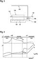
- Fig. 1 shows a schematic view of a cooling regulation system 100 according to embodiments described herein.
- the cooling regulation system 100 includes a valve 110 having a control device 120 provided in the interior of the valve 110.
- the control device 120 is configured for controlling an opening of an orifice 111 provided between a valve inlet 112 and a valve outlet 113 such that a flow of a coolant from the valve inlet 112 to the valve outlet 113 can be regulated.
- the cooling regulation system 100 includes an evaporator 130 with a contact surface that is adapted to be thermally connected to a heat source 140, 141 such that a thermal load from the heat source 140, 141 is dissipated by the evaporator in an operating state of the cooling regulation system 100.
- the cooling regulation system 100 includes a regulation device 150 configured for providing a temperature dependent gas pressure to the valve 110 for regulating a position of the control device 120 in order to regulate the flow of the coolant.
- the regulation device 150 is in thermal contact with the evaporator 130 at a position at which a vapor quality ⁇ of the coolant is ⁇ ⁇ ⁇ cr , wherein ⁇ cr is the critical vapor quality.
- the critical vapor quality ⁇ cr corresponds to the critical value at the transition from the annular flow regime, where cooling is efficient, to the wall dry-out regime, where cooling efficiency drops but vapor quality is still smaller than 1.
- the critical vapor quality ⁇ cr corresponds to the critical value at the transition from a flow regime where cooling is efficient to a regime where cooling efficiency decreases but vapor quality is still smaller than 1, such as the transition from the annular flow regime to the wall dry-out regime. Accordingly, it is to be understood that at the critical vapor quality ⁇ cr there is a transition such that: (a) there is a change of flow regime, (b) cooling efficiency decreases strongly, and (c) the fluid remains in the saturated state ( ⁇ 1).
- the embodiments as described herein provide for a self-regulating cooling regulation system which are configured for regulating the cooling efficiency of the evaporator.
- the embodiments as described herein have the advantage that a self-regulation of the cooling efficiency of the evaporator can be provided without any additional energy supply or electronic control loop such that a compact and failure resistant cooling regulation system is provided.
- the regulation device 150 is positioned in a heat flow path between the heat source 140, e.g. one or more IGBT submodules 141, and at least one channel of an array of channels 170 of the evaporator 130 through which the coolant is provided, as schematically shown in Fig. 2 .
- the flow of coolant in the evaporator 130 typically takes place in an array of channels 170 arranged in parallel.
- thermal losses in IGBTs can create a heat flux between IGBT submodules 141 and the coolant flowing through the channels of the array of channels 170.
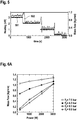
- the heat transfer coefficient (h) between the evaporator and the coolant is not constant along the flow direction (z) of the coolant in the evaporator, but depends on the vapor quality ⁇ of the fluid, as exemplarily shown in Fig. 4 .
- the heat transfer deteriorates rapidly.
- the heat source e.g. a part of an IGBT.
- IGBTs are mentioned as heat source, any other heat sources, which require two-phase cooling, can be used instead.
- the cooling regulation system in which the regulation device is in thermal contact with the evaporator at a position at which a vapor quality ⁇ of the coolant is ⁇ ⁇ ⁇ cr ( ⁇ cr being the critical vapor quality), beneficially provide for a regulation of the cooling efficiency of the evaporator.
- the coolant may be water, a dielectric refrigerant such as a hydrofluorocarbon, e.g. refrigerant R134a, or any other suitable coolant.
- the regulation device 150 can include a bulb containing a solid adsorbent 155.
- the solid absorbent can be activated carbon and/or silica gel and/or zeolite.
- the bulb of the regulation device 150 is an adsorption charge bulb instead of a refrigerant-charged bulb. Accordingly, it is to be understood that for the regulation device of the cooling regulation system as described herein, the amount of adsorbed/desorbed charge varies with temperature. Therefore, advantageously the regulation device is configured for providing an operating bulb pressure P b without the danger of condensation in the valve head.
- the bulb is set in thermal contact with the evaporator at such a spot near the array of channels, where the vapor quality of the coolant is expected to be maximum.
- this spot or position can be somewhere in the vicinity of the evaporator outlet.
- the exact location of the bulb may depend on the specific 3D arrangement of the coolant channels of the array of channels.
- the regulation device including the bulb containing the solid adsorbent is not controlling the superheat, but rather the cooling efficiency of the evaporator. Therefore, in contrast to conventional systems in which a bulb is set in thermal contact with the vapor which leaves the evaporator, in some embodiments of the cooling regulation system as described herein the bulb is set in thermal contact with the evaporator itself. As described herein, the spot or position at the evaporator for placing the bulb is strategically selected between the coolant channels, e.g. the array of channels of the evaporator, and the heat source, e.g. IGBT submodules being hotter than the fluid channels.
- the coolant channels e.g. the array of channels of the evaporator
- the heat source e.g. IGBT submodules being hotter than the fluid channels.
- the valve can include a first valve portion 110A connected to the regulation device 150 and a second valve portion 110B connected to the evaporator 130 via the valve outlet 113.
- the first valve portion 110A and the regulation device 150 may contain a gas having a temperature dependent pressure.
- the control device 120 can include a membrane 121 separating the first valve portion 110A and the second valve portion 110B. More specifically, the control device 120 may include a rod-like element 122 rigidly connected to the membrane 121. For instance, the rod-like element 122 can have an adjustment element 123 configured for adjusting the opening of the orifice 111, as exemplarily shown in Fig. 1 .
- the cooling regulation system may further include an adjustment device 160 configured for adjusting the response characteristic of the control device 120.
- the adjustment device 160 may include a spring element 161 having a first end 161A and a second end 161B.
- the first end 161A is attached to the rod-like element 122 and the second end 161B is attached to a regulating screw 162 provided in a wall 118 of the valve 110, as exemplarily shown in Fig. 1 .
- the coolant enters the valve 110 at the valve inlet 112 in a subcooled and purely liquid state and leaves the valve 110 at the valve outlet 113 in a subcooled state.
- the pressure of the coolant at the valve outlet 113 may be lower than the pressure at the valve inlet 112. Accordingly, by providing the coolant to the valve in a subcooled liquid state has the advantage that a generation of vapor can be avoided.
- the avoidance of coolant vapor generation is in particular beneficial since vaporized coolant provided to the evaporator would increase the coolant fluid velocity at the evaporator header which has a negative effect on the coolant fluid distribution in the evaporator, particularly with a multichannel structure. Therefore, in the embodiments described herein, the coolant is provided in a subcooled liquid state at the valve inlet 112 as well as at the valve outlet 113.
- the coolant enters the evaporator inlet 131 of the evaporator 130.
- the coolant typically flows in array of channels 170 and accepts heat from the heat source 140, for example including one or more IGBT submodules 141.
- the coolant typically leaves the evaporator 130 via an evaporator outlet 132 in a saturated state (in a steady condition) with vapor quality ⁇ out ⁇ x cr , wherein ⁇ cr is the critical vapor quality which is typically ⁇ cr ⁇ 1.
- the flow of the coolant is regulated by a variable opening of the orifice 111 via a movement of a rod-like element 122, rigidly connected to a membrane 121.
- the membrane 121 typically separates two volumes, in particular a first valve portion 110A and a second valve portion 110B.
- the first valve portion 110A is connected to the regulation device 150, e.g. by a tube 151.
- the regulation device can include a bulb containing a solid adsorbent, such as activated carbon, silica gel, zeolite, etc.
- the first valve portion 110A and the regulation device 150 are typically filled with a specially selected gas ("charge") at a certain pressure ( P b ) which varies with the temperature of the bulb.
- a certain pressure ( P b ) which varies with the temperature of the bulb.
- the pressure ( P e ) in the a second valve portion 110B is equal to the pressure of valve outlet 113, which can be close to the evaporator inlet pressure, provided that the pressure drop between the valve and the evaporator is small.
- the expected evaporator pressure P e is an external parameter determined by the operation point of the complete cooling system.
- the solid adsorbent, in the bulb should be selected such that, in the range of operation pressures and at maximum potential heat flux, T e - T fl ⁇ ⁇ T max holds, where T e corresponds to the evaporator temperature, T fl corresponds to the temperature of the coolant fluid, and ⁇ T max corresponds to the value at the critical vapor quality ⁇ cr , as exemplarily shown in Figure 4 .
- the cooling regulation system as described herein is capable of adjusting the opening of the orifice 111 automatically, i.e. by self-regulation, in case of a variation of the heat flux from the heat source to the evaporator.
- the difference ⁇ T between the evaporator temperature and the saturation temperature of the coolant T sat ( P e ) at any point of the evaporator should be smaller than ⁇ T max , since the vapor quality ⁇ would be lower than that at the point where the bulb is positioned, resulting in higher heat transfer coefficients h , as exemplarily shown in Fig. 4 .
- the bulb of the regulation device can be in thermal contact with the evaporator 130.
- the bulb pressure P b increases or decreases, causing the membrane 121 to flex.
- This flexing of the membrane causes a movement of the rod-like element 122 such that the flow of the coolant is regulated.
- the bulb pressure P b increases, the opening of the orifice 111 increases such that an increased coolant flow is provided.
- the bulb pressure P b decreases the opening of the orifice 111 decreases such that a decreased coolant flow is provided.
- a cooling regulation system suitable for purely mechanical flow regulation.
- the embodiments of the cooling regulation system are configured for automatically adjusting a flow resistance of the coolant.
- the cooling regulation system as described herein is configured for responding to changing heat, e.g. generated by IGBTs.
- embodiments of the cooling regulation system as described herein are configured to be self-regulating, such that no additional electronic control loop or energy supply is necessary.
- the cooling regulation system as described herein provides for a more compact and failure resistant design in comparison to conventional cooling regulation systems.
- the evaporator may include multiple evaporators provided in a stack.
- the multiple evaporators may be connected to a valve and a regulation device as described herein.
- the multiple evaporators can be provided in a vertical stack or in a horizontal stack or any other three-dimensional arrangement.
- the evaporator pressures P e are not the same for all evaporators of the multiple evaporators in a stack arrangement, the differences of the evaporator pressures P e can beneficially be compensated via an individual setting of the regulating screw 162 for each regulation valve as described herein. Accordingly, an even distribution of temperatures across multiple heat sources to be cooled, e.g. multiple IGBTs, is possible.
- the evaporator can be a flat extruded multiport evaporator.
- FIG. 3 shows a schematic view of a part of the cooling regulation system in which the regulation device 150 is in thermal contact with a thermally conducting element 190 which is in thermal contact with a heater 180 provided at an outlet piping of the evaporator 130.
- the cooling regulation system 100 includes a valve 110 having an control device 120 provided in the interior of the valve 110.
- the control device 120 is configured for controlling an opening of an orifice 111 provided between a valve inlet 112 and a valve outlet 113 such that a flow of a coolant from the valve inlet 112 to the valve outlet 113 can be regulated.
- the cooling regulation system 100 includes an evaporator 130 with a contact surface that is adapted to be thermally connected to a heat source 140, 141 such that a thermal load from the heat source 140, 141 is dissipated by the evaporator in an operating state of the cooling regulation system 100.
- the evaporator 130 typically has an evaporator inlet 131 which can be connected to the valve outlet 113.
- the cooling regulation system 100 further includes a heater 180 provided at an outlet piping of the evaporator 130.
- the heater 180 is in thermal contact with the outlet piping via a thermally conducting element 190.
- a regulation device 150 is provided which is configured for providing a temperature dependent gas pressure to the valve 110 for regulating a position of the control device 120 in order to regulate the flow of the coolant.
- the regulation device 150 is in thermal contact with the thermally conducting element 190.
- the heater 180 is configured to provide a fixed heating power which is selected such that the heat flux through the thermally conducting element 190 is similar to the maximum potential heat flux through the evaporator 130.
- the embodiment as exemplary shown in Fig. 3 provides an alternative configuration for a cooling regulation system which has the same advantages as the embodiment described with reference to Fig. 1 .
- a cooling regulation system having a regulation device 150 in thermal contact with a heater 180 via a thermally conducting element 190 also a self-regulating system capable of regulating the cooling efficiency of the evaporator can be provided such that no additional electronic control loop is needed and a compact and failure resistant cooling regulation system is provided.
- a commercial TEV with suitable characteristics may be used.
- a thermostatic expansion valve TMVX-00101 manufactured by Honeywell, with an adsorber charge of the bulb can be used.
- the bulb can be thermally contacted with a 2 mm thick aluminum plate, installed between the array of channels and the heater source to be cooled.
- the valve can be configured to use external equalization at the outlet header pressure.
- the characteristics of the thermostatic expansion valve TMVX-00101 is dimensioned for R22 and T ⁇ 15°C; therefore, this particular valve is fully functional in a setup with T bulb >35°C (or P e >8.8 bar).
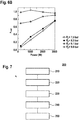
- an exemplary graph of the mass flow rate as a function of heating power for several set values of the evaporator pressure is shown in Fig. 6A and an exemplary graph of an outlet vapor quality as a function of heating power for several set values of the evaporator pressure is shown in Fig. 6B .
- the method 200 for automatic cooling regulation includes providing 210 a coolant in a subcooled state into a valve 110 via a valve inlet 112. Further the method includes guiding 220 the coolant through an orifice 111 having a controllable opening into an evaporator 130, wherein the orifice 111 is provided between the valve inlet 112 and a valve outlet 113 connected to the evaporator 130.
- the method includes providing 230 a first heat transfer from a heat source 140, 141 to the coolant in the evaporator 130 such that a thermal load from the heat source 140, 141 is dissipated by the evaporator in an operating state of the cooling regulation system 100. Further; the method includes providing 240 a second heat transfer to a regulation device 150 configured for providing a temperature dependent gas pressure to the valve 110 in order to regulate a coolant flow.
- the regulation device 150 is either in thermal contact with the evaporator 130 at a position at which a vapor quality ⁇ of the coolant is ⁇ ⁇ ⁇ cr (as exemplarily described with reference to Fig. 1 ), or alternatively the regulation device 150 is in thermal contact with a thermally conducting element 190 which is in thermal contact with a heater 180 provided at an outlet piping of the evaporator 130 (as exemplarily described with reference to Fig. 3 ), wherein the heater 180 is configured to provide a fixed heating power which is selected such that the heat flux through the thermally conducting element 190 is similar to a maximum potential heat flux through the evaporator 130.
- the method includes regulating 250 the coolant flow by a control device 120 provided in the interior of the valve 110, wherein the control device 120 is configured for a controlling the opening of the orifice 111 provided between the valve inlet 112 and the valve outlet 113.
- regulating 250 the coolant flow results in regulating the cooling efficiency of the evaporator 130.
- a self-regulating cooling method is provided with which the cooling efficiency of an evaporator can be regulated, e.g. maintained in an optimum range.
- the method may further include discharging the coolant from the evaporator in a saturated state.
- regulating 250 the coolant flow by the control device 120 may include flexing a membrane 121 of the control device 120 such that a rod-like element 122 rigidly connected to the membrane 121 is movable in order to control the opening of the orifice 111 by an adjustment element 123 of the rod-like element 122, as exemplarily described with reference to Fig. 1 .
- the method may include adjusting the response characteristic of the control device 120 by an adjustment device 160, as exemplarily described with reference to Fig. 1 .
- embodiments of the cooling regulation system as described herein are fully passive, i.e. no electric current supply for a flow regulation unit is needed. This allows for installation in areas where using an auxiliary electric supply and electric cables is complicated, e.g., in high-voltage areas.
- the coolant flow rate is self-regulating for the available variable heating load, without dedicated control electronics. Accordingly, the cooling efficiency is automatically adjusted to the necessary level to prevent fluid dry-out and, therefore, dangerous overheating of transistors. Further, an even distribution of coolant flow across multiple evaporators, e.g.
- a further advantage of the system and a method according to embodiments described herein is that the optimum flow rate will be automatically corrected in case the flow resistance and heat transfer deteriorate with time, for instance due to fouling or other reasons. Further, the automatic reduction of coolant flow to the minimum necessary level beneficially leads to reduced wear of the tubing and a reduction of pump load.
- the embodiments described herein are in particular suitable for two-phase cooling systems of an AC-DC converter comprising multiple IGBTs.
- one of the potential applications are the next-generation high voltage direct current (HVDC) converter under development at ABB, particularly well-suited for offshore converters for wind and similar applications.
- HVDC high voltage direct current
Landscapes
- Engineering & Computer Science (AREA)
- Physics & Mathematics (AREA)
- Thermal Sciences (AREA)
- Mechanical Engineering (AREA)
- General Engineering & Computer Science (AREA)
- Life Sciences & Earth Sciences (AREA)
- Sustainable Development (AREA)
- Fluid Mechanics (AREA)
- Microelectronics & Electronic Packaging (AREA)
- Cooling Or The Like Of Electrical Apparatus (AREA)
Claims (15)
- Système de régulation de refroidissement (100), comprenant:une soupape (110) équipée d'un dispositif de commande (120) prévu à l'intérieur de la soupape (110), dans lequel le dispositif de commande (120) est configuré de manière à commander une ouverture d'un orifice (111) prévu entre une entrée de soupape (112) et une sortie de soupape (113) de telle sorte qu'un écoulement d'un agent de refroidissement à partir de l'entrée de soupape (112) jusqu'à la sortie de soupape (113) puisse être régulé;un évaporateur (130) présentant une surface de contact qui est adaptée pour être connectée thermiquement à une source de chaleur (140, 141), de telle sorte qu'une charge thermique en provenance de la source de chaleur (140, 141) soit dissipée par l'évaporateur dans un état de fonctionnement du système de régulation de refroidissement (100), l'évaporateur (130) présentant une entrée d'évaporateur (131) connectée à la sortie de soupape (113); etun dispositif de régulation (150) configuré de manière à fournir une pression de gaz dépendant de la température à la soupape (110) afin de réguler une position du dispositif de commande (120) dans le but de réguler l'écoulement de l'agent de refroidissement;dans lequel le dispositif de régulation (150) se trouve en contact thermique avec l'évaporateur (130) à une position dans laquelle une qualité de vapeur χ de l'agent de refroidissement est χ ≤ χcr, où χcr est la qualité de vapeur critique,le dispositif de régulation (150) est positionné dans un chemin d'écoulement de chaleur entre la source de chaleur (140, 141) et au moins un canal d'un réseau de canaux (170) de l'évaporateur (130) à travers lesquels l'agent de refroidissement est fourni.
- Système de régulation de refroidissement (100) selon la revendication 1, dans lequel le dispositif de régulation (150) comprend une ampoule contenant un adsorbant solide (155), en particulier du charbon actif et/ou du gel de silice et/ou de la zéolite.
- Système de régulation de refroidissement (100) selon l'une quelconque des revendications 1 à 2, dans lequel la soupape (110) comprend une première partie de soupape (110A) qui est connectée au dispositif de régulation (150) et une seconde partie de soupape (110B) qui est connectée à l'évaporateur (130) par l'intermédiaire de la sortie de soupape (113).
- Système de régulation de refroidissement (100) selon la revendication 3, dans lequel la première partie de soupape (110A) et le dispositif de régulation (150) contiennent un gaz qui affiche une pression dépendant de la température.
- Système de régulation de refroidissement (100) selon la revendication 3 ou 4, dans lequel le dispositif de commande (120) comprend une membrane (121) qui sépare la première partie de soupape (110A) et la seconde partie de soupape (110B), et dans lequel le dispositif de commande (120) comprend un élément en forme de tige (122) qui est connecté de façon rigide à la membrane (121).
- Système de régulation de refroidissement (100) selon la revendication à 5, dans lequel l'élément en forme de tige (122) présente un élément de réglage (123) configuré de manière à régler l'ouverture de l'orifice (111) .
- Système de régulation de refroidissement (100) selon l'une quelconque des revendications 1 à 6, comprenant en outre un dispositif de réglage (160) configuré de manière à régler la caractéristique de réponse du dispositif de commande (120).
- Système de régulation de refroidissement (100) selon la revendication 7 et l'une quelconque des revendications 5 à 6, dans lequel le dispositif de réglage (160) comprend un élément de ressort (161) qui présente une première extrémité (161A) et une seconde extrémité (161B), dans lequel la première extrémité (161A) est attachée à l'élément en forme de tige (122), et dans lequel la seconde extrémité (161B) est attachée à une vis de régulation (162) prévue dans une paroi (118) de la soupape (110).
- Système de régulation de refroidissement (100), comprenant:une soupape (110) équipée d'un dispositif de commande (120) prévu à l'intérieur de la soupape (110), dans lequel le dispositif de commande (120) est configuré de manière à commander une ouverture d'un orifice (111) prévu entre une entrée de soupape (112) et une sortie de soupape (113) de telle sorte qu'un écoulement d'un agent de refroidissement à partir de l'entrée de soupape (112) jusqu'à la sortie de soupape (113) puisse être régulé;un évaporateur (130) présentant une surface de contact qui est adaptée pour être connectée thermiquement à une source de chaleur (140, 141) de telle sorte qu'une charge thermique en provenance de la source de chaleur (140, 141) soit dissipée par l'évaporateur dans un état de fonctionnement du système de régulation de refroidissement (100), l'évaporateur (130) présentant une entrée d'évaporateur (131) connectée à la sortie de soupape (113);un dispositif de chauffage (180) prévu au niveau d'une conduite de sortie de l'évaporateur (130), dans lequel le dispositif de chauffage (180) se trouve en contact thermique avec la conduite de sortie par l'intermédiaire d'une élément thermiquement conducteur (190) ;un dispositif de régulation (150) configuré de manière à fournir une pression de gaz dépendant de la température à la soupape (110) afin de réguler une position du dispositif de commande (120) dans le but de réguler l'écoulement de l'agent de refroidissement;dans lequel le dispositif de régulation (150) se trouve en contact thermique avec l'élément thermiquement conducteur (190), etle dispositif de chauffage (180) est configuré de manière à fournir une puissance de chauffage constante, dans lequel la puissance de chauffage constante est sélectionnée de telle sorte que le flux de chaleur à travers l'élément thermiquement conducteur (190) soit similaire au flux de chaleur potentiel maximum à travers l'évaporateur (130).
- Module de puissance, comprenant au moins un système de régulation de refroidissement (100) selon l'une quelconque des revendications 1 à 9, dans lequel au moins un composant parmi un composant électronique de génération de chaleur et un composant électrique de génération de chaleur est connecté thermiquement à la surface de contact de l'évaporateur (130).
- Procédé (200) de régulation de refroidissement automatique, comprenant les étapes suivantes:introduire (210) un agent de refroidissement dans un état sous-refroidi dans une soupape (110) par l'intermédiaire d'une entrée de soupape (112);guider (220) l'agent de refroidissement à travers un orifice (111) présentant une ouverture commandable dans un évaporateur (130), dans lequel l'orifice (111) est prévu entre l'entrée de soupape (112) et une sortie de soupape (113) connectée à l'évaporateur (130);appliquer (230) un premier transfert de chaleur à partir d'une source de chaleur (140, 141) à l'agent de refroidissement dans l'évaporateur (130) de telle sorte qu'une charge thermique en provenance de la source de chaleur (140, 141) soit dissipée par l'évaporateur dans un état de fonctionnement du système de régulation de refroidissement (100); eteffectuer (240) un second transfert de chaleur au niveau d'un dispositif de régulation (150) configuré de manière à fournir une pression de gaz dépendant de la température à la soupape (110) dans le but de réguler un écoulement d'agent de refroidissement,dans lequel soit le dispositif de régulation (150) se trouve en contact thermique avec l'évaporateur (130) à une position dans laquelle une qualité de vapeur χ de l'agent de refroidissement est χ ≤ χcr, où χcr est la qualité de vapeur critique, le dispositif de régulation (150) étant positionné dans un chemin d'écoulement de chaleur entre la source de chaleur (140, 141) et au moins un canal d'un réseau de canaux (170) de l'évaporateur (130) à travers lesquels l'agent de refroidissement est prévu, soitdans lequel le dispositif de régulation (150) se trouve en contact thermique avec un élément thermiquement conducteur (190) qui se trouve en contact thermique avec un dispositif de chauffage (180) prévu au niveau d'une conduite de sortie de l'évaporateur (130), dans lequel le dispositif de chauffage (180) est configuré de manière à fournir une puissance de chauffage constante qui est sélectionnée de telle sorte que le flux de chaleur à travers l'élément thermiquement conducteur (190) soit similaire à un flux de chaleur potentiel maximum à travers l'évaporateur (130); etréguler (250) l'écoulement d'agent de refroidissement à l'aide d'un dispositif de commande (120) prévu à l'intérieur de la soupape (110), dans lequel le dispositif de commande (120) est configuré de manière à commander l'ouverture de l'orifice (111) prévu entre l'entrée de soupape (112) et la sortie de soupape (113) .
- Procédé selon la revendication 11, dans lequel la régulation (250) de l'écoulement d'agent de refroidissement résulte en la régulation de l'efficacité de refroidissement de l'évaporateur (130).
- Procédé selon la revendication 11 ou 12, comprenant en outre la décharge (260) de l'agent de refroidissement à partir de l'évaporateur dans un état saturé.
- Procédé selon l'une quelconque des revendications 11 à 13, dans lequel la régulation (250) de l'écoulement d'agent de refroidissement par le dispositif de commande (120) comprend la flexion d'une membrane (121) du dispositif de commande (120) de telle sorte qu'un élément en forme de tige (10) qui est connecté de façon rigide à la membrane (121) soit déplaçable dans le but de commander l'ouverture de l'orifice (111) par un élément de réglage (123) de l'élément en forme de tige (122) .
- Procédé selon l'une quelconque des revendications 11 à 14, comprenant en outre le réglage (270) de la caractéristique de réponse du dispositif de commande (120) à l'aide d'un dispositif de réglage (160).
Priority Applications (2)
| Application Number | Priority Date | Filing Date | Title |
|---|---|---|---|
| EP17150530.8A EP3346221B1 (fr) | 2017-01-06 | 2017-01-06 | Système de régulation de refroidissement et procédé de régulation de refroidissement |
| CN201810011175.0A CN108458519B (zh) | 2017-01-06 | 2018-01-05 | 冷却调整系统、功率模块和用于自动冷却调整的方法 |
Applications Claiming Priority (1)
| Application Number | Priority Date | Filing Date | Title |
|---|---|---|---|
| EP17150530.8A EP3346221B1 (fr) | 2017-01-06 | 2017-01-06 | Système de régulation de refroidissement et procédé de régulation de refroidissement |
Publications (2)
| Publication Number | Publication Date |
|---|---|
| EP3346221A1 EP3346221A1 (fr) | 2018-07-11 |
| EP3346221B1 true EP3346221B1 (fr) | 2020-03-04 |
Family
ID=57794126
Family Applications (1)
| Application Number | Title | Priority Date | Filing Date |
|---|---|---|---|
| EP17150530.8A Active EP3346221B1 (fr) | 2017-01-06 | 2017-01-06 | Système de régulation de refroidissement et procédé de régulation de refroidissement |
Country Status (2)
| Country | Link |
|---|---|
| EP (1) | EP3346221B1 (fr) |
| CN (1) | CN108458519B (fr) |
Families Citing this family (3)
| Publication number | Priority date | Publication date | Assignee | Title |
|---|---|---|---|---|
| JP7403984B2 (ja) * | 2019-07-26 | 2023-12-25 | 株式会社鷺宮製作所 | 冷却装置 |
| CN110672659A (zh) * | 2019-10-31 | 2020-01-10 | 北京机械设备研究所 | 一种双面水冷板散热性能测试装置及测试方法 |
| GB2592415A (en) * | 2020-02-27 | 2021-09-01 | Oxford Instruments Nanotechnology Tools Ltd | Insert for a cryogenic cooling system |
Family Cites Families (7)
| Publication number | Priority date | Publication date | Assignee | Title |
|---|---|---|---|---|
| US3414050A (en) * | 1967-04-11 | 1968-12-03 | Navy Usa | Heat pipe control apparatus |
| DE2753660A1 (de) * | 1977-12-02 | 1979-06-07 | Philips Patentverwaltung | Waermetransportsystem mit einer vorrichtung zur unterbrechung des waermetransportmittelrueckflusses |
| JPH01230966A (ja) * | 1988-03-10 | 1989-09-14 | Fuji Koki Seisakusho:Kk | 冷凍システムの制御方法及び温度膨脹弁 |
| JPH0445393A (ja) * | 1990-06-12 | 1992-02-14 | Aisin Seiki Co Ltd | ループ型ヒートパイプ式熱交換器 |
| EP0670460B1 (fr) * | 1994-03-03 | 1999-06-16 | Denso Corporation | Appareil frigorifique |
| US20070017239A1 (en) * | 2005-07-22 | 2007-01-25 | Monson Robert J | Self-regulating temperature control system |
| JP6380563B2 (ja) * | 2015-02-09 | 2018-08-29 | 富士通株式会社 | 冷却装置及び電子機器 |
-
2017
- 2017-01-06 EP EP17150530.8A patent/EP3346221B1/fr active Active
-
2018
- 2018-01-05 CN CN201810011175.0A patent/CN108458519B/zh active Active
Non-Patent Citations (1)
| Title |
|---|
| None * |
Also Published As
| Publication number | Publication date |
|---|---|
| CN108458519A (zh) | 2018-08-28 |
| CN108458519B (zh) | 2021-11-26 |
| EP3346221A1 (fr) | 2018-07-11 |
Similar Documents
| Publication | Publication Date | Title |
|---|---|---|
| US10036578B1 (en) | Integrated cold plate with expansion device and uniform cooling method achieved therewith | |
| KR101047832B1 (ko) | 전자 디바이스의 온도제어장치 및 온도제어방법 | |
| EP3346221B1 (fr) | Système de régulation de refroidissement et procédé de régulation de refroidissement | |
| CN103149949B (zh) | 一种基于帕尔贴效应的气体微流量控制器 | |
| US20150135746A1 (en) | Parallel evaporator circuit with balanced flow | |
| JP2004527764A (ja) | 電子デバイスの温度制御装置及び温度制御方法 | |
| US20080093057A1 (en) | Cooling apparatus having an auxiliary chiller, and an apparatus and method of fabricating a semiconductor device using the same | |
| US20140037277A1 (en) | Heat medium heating device and vehicular air-conditioning device including the same | |
| SE437424B (sv) | Ventil for vetskeinsprutning i en kylmedelforangare | |
| US12306124B2 (en) | Measuring device having an electrothermal transducer for adjusting a thermal resistance, and method of operating the same | |
| CN115693357A (zh) | 一种用于激光器散热的分区散热架构 | |
| KR100882382B1 (ko) | 전기 액화 석유 가스 증발기 | |
| CN1171054C (zh) | 制冷设备的调节方法以及制冷设备和膨胀阀 | |
| CN107078362A (zh) | 温度控制装置 | |
| EP1261984B1 (fr) | Systeme de traitement thermique d'un substrat | |
| US20230024244A1 (en) | Method for operating a heat exchanger, and energy store heat exchange system | |
| US20050262861A1 (en) | Method and apparatus for controlling cooling with coolant at a subambient pressure | |
| CN223274414U (zh) | 一种多并联工况下流量自适应调节系统 | |
| CN107992127A (zh) | 基于动态热容滤波的高精度恒温循环冷却水装置 | |
| KR101575505B1 (ko) | 공정온도 조절 장치 | |
| JP7508424B2 (ja) | 冷却装置 | |
| WO2021250414A1 (fr) | Réseau de led | |
| CN112185913B (zh) | 换热基板组件、换热模块、控制器、空调器 | |
| EP3108748A1 (fr) | Réservoir à poissons d'aquarium utilisant une pluralité d'éléments peltier et procédé de réglage de température d'eau d'élevage | |
| US12474725B2 (en) | On-demand flow rate adapter for flow rate adjustment in liquid cooling solutions |
Legal Events
| Date | Code | Title | Description |
|---|---|---|---|
| PUAI | Public reference made under article 153(3) epc to a published international application that has entered the european phase |
Free format text: ORIGINAL CODE: 0009012 |
|
| STAA | Information on the status of an ep patent application or granted ep patent |
Free format text: STATUS: THE APPLICATION HAS BEEN PUBLISHED |
|
| AK | Designated contracting states |
Kind code of ref document: A1 Designated state(s): AL AT BE BG CH CY CZ DE DK EE ES FI FR GB GR HR HU IE IS IT LI LT LU LV MC MK MT NL NO PL PT RO RS SE SI SK SM TR |
|
| AX | Request for extension of the european patent |
Extension state: BA ME |
|
| STAA | Information on the status of an ep patent application or granted ep patent |
Free format text: STATUS: REQUEST FOR EXAMINATION WAS MADE |
|
| 17P | Request for examination filed |
Effective date: 20181217 |
|
| RBV | Designated contracting states (corrected) |
Designated state(s): AL AT BE BG CH CY CZ DE DK EE ES FI FR GB GR HR HU IE IS IT LI LT LU LV MC MK MT NL NO PL PT RO RS SE SI SK SM TR |
|
| GRAP | Despatch of communication of intention to grant a patent |
Free format text: ORIGINAL CODE: EPIDOSNIGR1 |
|
| STAA | Information on the status of an ep patent application or granted ep patent |
Free format text: STATUS: GRANT OF PATENT IS INTENDED |
|
| RIC1 | Information provided on ipc code assigned before grant |
Ipc: F28D 15/06 20060101ALI20190329BHEP Ipc: F28D 15/02 20060101ALI20190329BHEP Ipc: F25B 49/02 20060101ALI20190329BHEP Ipc: F28F 27/02 20060101AFI20190329BHEP Ipc: H05K 7/20 20060101ALI20190329BHEP Ipc: F25B 41/06 20060101ALI20190329BHEP |
|
| INTG | Intention to grant announced |
Effective date: 20190430 |
|
| GRAJ | Information related to disapproval of communication of intention to grant by the applicant or resumption of examination proceedings by the epo deleted |
Free format text: ORIGINAL CODE: EPIDOSDIGR1 |
|
| STAA | Information on the status of an ep patent application or granted ep patent |
Free format text: STATUS: REQUEST FOR EXAMINATION WAS MADE |
|
| GRAP | Despatch of communication of intention to grant a patent |
Free format text: ORIGINAL CODE: EPIDOSNIGR1 |
|
| STAA | Information on the status of an ep patent application or granted ep patent |
Free format text: STATUS: GRANT OF PATENT IS INTENDED |
|
| INTC | Intention to grant announced (deleted) | ||
| INTG | Intention to grant announced |
Effective date: 20190920 |
|
| GRAS | Grant fee paid |
Free format text: ORIGINAL CODE: EPIDOSNIGR3 |
|
| GRAA | (expected) grant |
Free format text: ORIGINAL CODE: 0009210 |
|
| STAA | Information on the status of an ep patent application or granted ep patent |
Free format text: STATUS: THE PATENT HAS BEEN GRANTED |
|
| AK | Designated contracting states |
Kind code of ref document: B1 Designated state(s): AL AT BE BG CH CY CZ DE DK EE ES FI FR GB GR HR HU IE IS IT LI LT LU LV MC MK MT NL NO PL PT RO RS SE SI SK SM TR |
|
| REG | Reference to a national code |
Ref country code: GB Ref legal event code: FG4D |
|
| REG | Reference to a national code |
Ref country code: CH Ref legal event code: EP |
|
| REG | Reference to a national code |
Ref country code: AT Ref legal event code: REF Ref document number: 1240869 Country of ref document: AT Kind code of ref document: T Effective date: 20200315 |
|
| REG | Reference to a national code |
Ref country code: DE Ref legal event code: R096 Ref document number: 602017012419 Country of ref document: DE |
|
| REG | Reference to a national code |
Ref country code: IE Ref legal event code: FG4D |
|
| PG25 | Lapsed in a contracting state [announced via postgrant information from national office to epo] |
Ref country code: NO Free format text: LAPSE BECAUSE OF FAILURE TO SUBMIT A TRANSLATION OF THE DESCRIPTION OR TO PAY THE FEE WITHIN THE PRESCRIBED TIME-LIMIT Effective date: 20200604 Ref country code: RS Free format text: LAPSE BECAUSE OF FAILURE TO SUBMIT A TRANSLATION OF THE DESCRIPTION OR TO PAY THE FEE WITHIN THE PRESCRIBED TIME-LIMIT Effective date: 20200304 Ref country code: FI Free format text: LAPSE BECAUSE OF FAILURE TO SUBMIT A TRANSLATION OF THE DESCRIPTION OR TO PAY THE FEE WITHIN THE PRESCRIBED TIME-LIMIT Effective date: 20200304 |
|
| REG | Reference to a national code |
Ref country code: NL Ref legal event code: MP Effective date: 20200304 |
|
| PG25 | Lapsed in a contracting state [announced via postgrant information from national office to epo] |
Ref country code: HR Free format text: LAPSE BECAUSE OF FAILURE TO SUBMIT A TRANSLATION OF THE DESCRIPTION OR TO PAY THE FEE WITHIN THE PRESCRIBED TIME-LIMIT Effective date: 20200304 Ref country code: LV Free format text: LAPSE BECAUSE OF FAILURE TO SUBMIT A TRANSLATION OF THE DESCRIPTION OR TO PAY THE FEE WITHIN THE PRESCRIBED TIME-LIMIT Effective date: 20200304 Ref country code: SE Free format text: LAPSE BECAUSE OF FAILURE TO SUBMIT A TRANSLATION OF THE DESCRIPTION OR TO PAY THE FEE WITHIN THE PRESCRIBED TIME-LIMIT Effective date: 20200304 Ref country code: BG Free format text: LAPSE BECAUSE OF FAILURE TO SUBMIT A TRANSLATION OF THE DESCRIPTION OR TO PAY THE FEE WITHIN THE PRESCRIBED TIME-LIMIT Effective date: 20200604 Ref country code: GR Free format text: LAPSE BECAUSE OF FAILURE TO SUBMIT A TRANSLATION OF THE DESCRIPTION OR TO PAY THE FEE WITHIN THE PRESCRIBED TIME-LIMIT Effective date: 20200605 |
|
| REG | Reference to a national code |
Ref country code: LT Ref legal event code: MG4D |
|
| PG25 | Lapsed in a contracting state [announced via postgrant information from national office to epo] |
Ref country code: NL Free format text: LAPSE BECAUSE OF FAILURE TO SUBMIT A TRANSLATION OF THE DESCRIPTION OR TO PAY THE FEE WITHIN THE PRESCRIBED TIME-LIMIT Effective date: 20200304 |
|
| PG25 | Lapsed in a contracting state [announced via postgrant information from national office to epo] |
Ref country code: RO Free format text: LAPSE BECAUSE OF FAILURE TO SUBMIT A TRANSLATION OF THE DESCRIPTION OR TO PAY THE FEE WITHIN THE PRESCRIBED TIME-LIMIT Effective date: 20200304 Ref country code: CZ Free format text: LAPSE BECAUSE OF FAILURE TO SUBMIT A TRANSLATION OF THE DESCRIPTION OR TO PAY THE FEE WITHIN THE PRESCRIBED TIME-LIMIT Effective date: 20200304 Ref country code: LT Free format text: LAPSE BECAUSE OF FAILURE TO SUBMIT A TRANSLATION OF THE DESCRIPTION OR TO PAY THE FEE WITHIN THE PRESCRIBED TIME-LIMIT Effective date: 20200304 Ref country code: SM Free format text: LAPSE BECAUSE OF FAILURE TO SUBMIT A TRANSLATION OF THE DESCRIPTION OR TO PAY THE FEE WITHIN THE PRESCRIBED TIME-LIMIT Effective date: 20200304 Ref country code: EE Free format text: LAPSE BECAUSE OF FAILURE TO SUBMIT A TRANSLATION OF THE DESCRIPTION OR TO PAY THE FEE WITHIN THE PRESCRIBED TIME-LIMIT Effective date: 20200304 Ref country code: SK Free format text: LAPSE BECAUSE OF FAILURE TO SUBMIT A TRANSLATION OF THE DESCRIPTION OR TO PAY THE FEE WITHIN THE PRESCRIBED TIME-LIMIT Effective date: 20200304 Ref country code: IS Free format text: LAPSE BECAUSE OF FAILURE TO SUBMIT A TRANSLATION OF THE DESCRIPTION OR TO PAY THE FEE WITHIN THE PRESCRIBED TIME-LIMIT Effective date: 20200704 Ref country code: PT Free format text: LAPSE BECAUSE OF FAILURE TO SUBMIT A TRANSLATION OF THE DESCRIPTION OR TO PAY THE FEE WITHIN THE PRESCRIBED TIME-LIMIT Effective date: 20200729 Ref country code: ES Free format text: LAPSE BECAUSE OF FAILURE TO SUBMIT A TRANSLATION OF THE DESCRIPTION OR TO PAY THE FEE WITHIN THE PRESCRIBED TIME-LIMIT Effective date: 20200304 |
|
| REG | Reference to a national code |
Ref country code: AT Ref legal event code: MK05 Ref document number: 1240869 Country of ref document: AT Kind code of ref document: T Effective date: 20200304 |
|
| REG | Reference to a national code |
Ref country code: DE Ref legal event code: R097 Ref document number: 602017012419 Country of ref document: DE |
|
| PLBE | No opposition filed within time limit |
Free format text: ORIGINAL CODE: 0009261 |
|
| STAA | Information on the status of an ep patent application or granted ep patent |
Free format text: STATUS: NO OPPOSITION FILED WITHIN TIME LIMIT |
|
| PG25 | Lapsed in a contracting state [announced via postgrant information from national office to epo] |
Ref country code: AT Free format text: LAPSE BECAUSE OF FAILURE TO SUBMIT A TRANSLATION OF THE DESCRIPTION OR TO PAY THE FEE WITHIN THE PRESCRIBED TIME-LIMIT Effective date: 20200304 Ref country code: DK Free format text: LAPSE BECAUSE OF FAILURE TO SUBMIT A TRANSLATION OF THE DESCRIPTION OR TO PAY THE FEE WITHIN THE PRESCRIBED TIME-LIMIT Effective date: 20200304 Ref country code: IT Free format text: LAPSE BECAUSE OF FAILURE TO SUBMIT A TRANSLATION OF THE DESCRIPTION OR TO PAY THE FEE WITHIN THE PRESCRIBED TIME-LIMIT Effective date: 20200304 |
|
| 26N | No opposition filed |
Effective date: 20201207 |
|
| PG25 | Lapsed in a contracting state [announced via postgrant information from national office to epo] |
Ref country code: PL Free format text: LAPSE BECAUSE OF FAILURE TO SUBMIT A TRANSLATION OF THE DESCRIPTION OR TO PAY THE FEE WITHIN THE PRESCRIBED TIME-LIMIT Effective date: 20200304 Ref country code: SI Free format text: LAPSE BECAUSE OF FAILURE TO SUBMIT A TRANSLATION OF THE DESCRIPTION OR TO PAY THE FEE WITHIN THE PRESCRIBED TIME-LIMIT Effective date: 20200304 |
|
| REG | Reference to a national code |
Ref country code: DE Ref legal event code: R081 Ref document number: 602017012419 Country of ref document: DE Owner name: HITACHI ENERGY SWITZERLAND AG, CH Free format text: FORMER OWNER: ABB SCHWEIZ AG, BADEN, CH Ref country code: DE Ref legal event code: R082 Ref document number: 602017012419 Country of ref document: DE Representative=s name: DENNEMEYER & ASSOCIATES S.A., DE Ref country code: DE Ref legal event code: R081 Ref document number: 602017012419 Country of ref document: DE Owner name: ABB POWER GRIDS SWITZERLAND AG, CH Free format text: FORMER OWNER: ABB SCHWEIZ AG, BADEN, CH Ref country code: DE Ref legal event code: R082 Ref document number: 602017012419 Country of ref document: DE Representative=s name: DENNEMEYER & ASSOCIATES RECHTSANWALTSGESELLSCH, DE Ref country code: DE Ref legal event code: R081 Ref document number: 602017012419 Country of ref document: DE Owner name: HITACHI ENERGY LTD, CH Free format text: FORMER OWNER: ABB SCHWEIZ AG, BADEN, CH |
|
| PG25 | Lapsed in a contracting state [announced via postgrant information from national office to epo] |
Ref country code: MC Free format text: LAPSE BECAUSE OF FAILURE TO SUBMIT A TRANSLATION OF THE DESCRIPTION OR TO PAY THE FEE WITHIN THE PRESCRIBED TIME-LIMIT Effective date: 20200304 |
|
| REG | Reference to a national code |
Ref country code: CH Ref legal event code: PL |
|
| PG25 | Lapsed in a contracting state [announced via postgrant information from national office to epo] |
Ref country code: LU Free format text: LAPSE BECAUSE OF NON-PAYMENT OF DUE FEES Effective date: 20210106 |
|
| REG | Reference to a national code |
Ref country code: BE Ref legal event code: MM Effective date: 20210131 |
|
| PG25 | Lapsed in a contracting state [announced via postgrant information from national office to epo] |
Ref country code: CH Free format text: LAPSE BECAUSE OF NON-PAYMENT OF DUE FEES Effective date: 20210131 Ref country code: LI Free format text: LAPSE BECAUSE OF NON-PAYMENT OF DUE FEES Effective date: 20210131 |
|
| REG | Reference to a national code |
Ref country code: GB Ref legal event code: 732E Free format text: REGISTERED BETWEEN 20211104 AND 20211110 |
|
| PG25 | Lapsed in a contracting state [announced via postgrant information from national office to epo] |
Ref country code: IE Free format text: LAPSE BECAUSE OF NON-PAYMENT OF DUE FEES Effective date: 20210106 |
|
| REG | Reference to a national code |
Ref country code: DE Ref legal event code: R081 Ref document number: 602017012419 Country of ref document: DE Owner name: HITACHI ENERGY SWITZERLAND AG, CH Free format text: FORMER OWNER: ABB POWER GRIDS SWITZERLAND AG, BADEN, CH Ref country code: DE Ref legal event code: R081 Ref document number: 602017012419 Country of ref document: DE Owner name: HITACHI ENERGY LTD, CH Free format text: FORMER OWNER: ABB POWER GRIDS SWITZERLAND AG, BADEN, CH |
|
| PG25 | Lapsed in a contracting state [announced via postgrant information from national office to epo] |
Ref country code: BE Free format text: LAPSE BECAUSE OF NON-PAYMENT OF DUE FEES Effective date: 20210131 |
|
| PG25 | Lapsed in a contracting state [announced via postgrant information from national office to epo] |
Ref country code: CY Free format text: LAPSE BECAUSE OF FAILURE TO SUBMIT A TRANSLATION OF THE DESCRIPTION OR TO PAY THE FEE WITHIN THE PRESCRIBED TIME-LIMIT Effective date: 20200304 |
|
| P01 | Opt-out of the competence of the unified patent court (upc) registered |
Effective date: 20230527 |
|
| PG25 | Lapsed in a contracting state [announced via postgrant information from national office to epo] |
Ref country code: HU Free format text: LAPSE BECAUSE OF FAILURE TO SUBMIT A TRANSLATION OF THE DESCRIPTION OR TO PAY THE FEE WITHIN THE PRESCRIBED TIME-LIMIT; INVALID AB INITIO Effective date: 20170106 |
|
| REG | Reference to a national code |
Ref country code: DE Ref legal event code: R082 Ref document number: 602017012419 Country of ref document: DE Representative=s name: DENNEMEYER & ASSOCIATES RECHTSANWALTSGESELLSCH, DE Ref country code: DE Ref legal event code: R082 Ref document number: 602017012419 Country of ref document: DE Representative=s name: DENNEMEYER & ASSOCIATES S.A., DE Ref country code: DE Ref legal event code: R081 Ref document number: 602017012419 Country of ref document: DE Owner name: HITACHI ENERGY LTD, CH Free format text: FORMER OWNER: HITACHI ENERGY SWITZERLAND AG, BADEN, CH |
|
| PG25 | Lapsed in a contracting state [announced via postgrant information from national office to epo] |
Ref country code: MK Free format text: LAPSE BECAUSE OF FAILURE TO SUBMIT A TRANSLATION OF THE DESCRIPTION OR TO PAY THE FEE WITHIN THE PRESCRIBED TIME-LIMIT Effective date: 20200304 |
|
| PG25 | Lapsed in a contracting state [announced via postgrant information from national office to epo] |
Ref country code: TR Free format text: LAPSE BECAUSE OF FAILURE TO SUBMIT A TRANSLATION OF THE DESCRIPTION OR TO PAY THE FEE WITHIN THE PRESCRIBED TIME-LIMIT Effective date: 20200304 |
|
| REG | Reference to a national code |
Ref country code: GB Ref legal event code: 732E Free format text: REGISTERED BETWEEN 20240718 AND 20240724 |
|
| PG25 | Lapsed in a contracting state [announced via postgrant information from national office to epo] |
Ref country code: MT Free format text: LAPSE BECAUSE OF FAILURE TO SUBMIT A TRANSLATION OF THE DESCRIPTION OR TO PAY THE FEE WITHIN THE PRESCRIBED TIME-LIMIT Effective date: 20200304 |
|
| REG | Reference to a national code |
Ref country code: DE Ref legal event code: R082 Ref document number: 602017012419 Country of ref document: DE Representative=s name: DENNEMEYER & ASSOCIATES RECHTSANWALTSGESELLSCH, DE |
|
| PGFP | Annual fee paid to national office [announced via postgrant information from national office to epo] |
Ref country code: GB Payment date: 20260123 Year of fee payment: 10 |
|
| PGFP | Annual fee paid to national office [announced via postgrant information from national office to epo] |
Ref country code: DE Payment date: 20260121 Year of fee payment: 10 |
|
| PGFP | Annual fee paid to national office [announced via postgrant information from national office to epo] |
Ref country code: FR Payment date: 20260123 Year of fee payment: 10 |