EP3346230B1 - Dispositif et procede de mesure de la courbure d'un fil - Google Patents
Dispositif et procede de mesure de la courbure d'un fil Download PDFInfo
- Publication number
- EP3346230B1 EP3346230B1 EP17150289.1A EP17150289A EP3346230B1 EP 3346230 B1 EP3346230 B1 EP 3346230B1 EP 17150289 A EP17150289 A EP 17150289A EP 3346230 B1 EP3346230 B1 EP 3346230B1
- Authority
- EP
- European Patent Office
- Prior art keywords
- wire
- camera
- curvature
- contour
- data
- Prior art date
- Legal status (The legal status is an assumption and is not a legal conclusion. Google has not performed a legal analysis and makes no representation as to the accuracy of the status listed.)
- Active
Links
Images



Classifications
-
- G—PHYSICS
- G01—MEASURING; TESTING
- G01B—MEASURING LENGTH, THICKNESS OR SIMILAR LINEAR DIMENSIONS; MEASURING ANGLES; MEASURING AREAS; MEASURING IRREGULARITIES OF SURFACES OR CONTOURS
- G01B11/00—Measuring arrangements characterised by the use of optical techniques
- G01B11/24—Measuring arrangements characterised by the use of optical techniques for measuring contours or curvatures
- G01B11/2433—Measuring arrangements characterised by the use of optical techniques for measuring contours or curvatures for measuring outlines by shadow casting
-
- B—PERFORMING OPERATIONS; TRANSPORTING
- B21—MECHANICAL METAL-WORKING WITHOUT ESSENTIALLY REMOVING MATERIAL; PUNCHING METAL
- B21C—MANUFACTURE OF METAL SHEETS, WIRE, RODS, TUBES, PROFILES OR LIKE SEMI-MANUFACTURED PRODUCTS OTHERWISE THAN BY ROLLING; AUXILIARY OPERATIONS USED IN CONNECTION WITH METAL-WORKING WITHOUT ESSENTIALLY REMOVING MATERIAL
- B21C51/00—Measuring, gauging, indicating, counting, or marking devices specially adapted for use in the production or manipulation of material in accordance with subclasses B21B - B21F
-
- B—PERFORMING OPERATIONS; TRANSPORTING
- B21—MECHANICAL METAL-WORKING WITHOUT ESSENTIALLY REMOVING MATERIAL; PUNCHING METAL
- B21F—WORKING OR PROCESSING OF METAL WIRE
- B21F1/00—Bending wire other than coiling; Straightening wire
- B21F1/02—Straightening
-
- G—PHYSICS
- G01—MEASURING; TESTING
- G01B—MEASURING LENGTH, THICKNESS OR SIMILAR LINEAR DIMENSIONS; MEASURING ANGLES; MEASURING AREAS; MEASURING IRREGULARITIES OF SURFACES OR CONTOURS
- G01B11/00—Measuring arrangements characterised by the use of optical techniques
- G01B11/24—Measuring arrangements characterised by the use of optical techniques for measuring contours or curvatures
- G01B11/245—Measuring arrangements characterised by the use of optical techniques for measuring contours or curvatures using a plurality of fixed, simultaneously operating transducers
-
- G—PHYSICS
- G01—MEASURING; TESTING
- G01B—MEASURING LENGTH, THICKNESS OR SIMILAR LINEAR DIMENSIONS; MEASURING ANGLES; MEASURING AREAS; MEASURING IRREGULARITIES OF SURFACES OR CONTOURS
- G01B11/00—Measuring arrangements characterised by the use of optical techniques
- G01B11/24—Measuring arrangements characterised by the use of optical techniques for measuring contours or curvatures
- G01B11/255—Measuring arrangements characterised by the use of optical techniques for measuring contours or curvatures for measuring radius of curvature
-
- G—PHYSICS
- G01—MEASURING; TESTING
- G01B—MEASURING LENGTH, THICKNESS OR SIMILAR LINEAR DIMENSIONS; MEASURING ANGLES; MEASURING AREAS; MEASURING IRREGULARITIES OF SURFACES OR CONTOURS
- G01B2210/00—Aspects not specifically covered by any group under G01B, e.g. of wheel alignment, caliper-like sensors
- G01B2210/54—Revolving an optical measuring instrument around a body
-
- G—PHYSICS
- G01—MEASURING; TESTING
- G01B—MEASURING LENGTH, THICKNESS OR SIMILAR LINEAR DIMENSIONS; MEASURING ANGLES; MEASURING AREAS; MEASURING IRREGULARITIES OF SURFACES OR CONTOURS
- G01B2210/00—Aspects not specifically covered by any group under G01B, e.g. of wheel alignment, caliper-like sensors
- G01B2210/58—Wireless transmission of information between a sensor or probe and a control or evaluation unit
Definitions
- the invention relates to a device for detecting a wire curvature, which comprises a wire guide. Furthermore, the invention relates to a wire straightening unit, which comprises a device according to the invention for detecting a wire curvature. Likewise, the invention relates to a method for determining the wire curvature with the aid of a device according to the invention and a method for wire straightening with the aid of the wire straightening unit according to the invention.
- Wire that is to be further processed or used for a specific purpose is usually supplied on spools and therefore has a certain curvature. This varies from case to case and depends, for example, on how much wire has already been unwound from the bobbin. If the wire with a different curvature, in particular in the straightest possible form needed, it is directed or stretched before further processing. In order to optimize this process, to measure its success and / or quality, or to determine if straightening is necessary at all, wire curvature detection devices are necessary. In this case, a rapid measurement, which can detect different wires in diameter and structure, enables a flexible use of such a device.
- the DE 195 03 850 C1 discloses a non-rotating straightening apparatus for bending machines with an integrated measuring device. A bend in the material is detected in the measuring device to then adjust at least one guide stone so that the bending tolerance is maintained. Bends in one or more planes can be detected and corrected. This can be done with an opto-electronic scanning with a band-shaped receiver with multiple receiver areas to determine if and how far the material deviates from the target pass axis.
- light sources 13, 14
- receivers 13 ', 14'
- LED with normal or IR light or photodiodes
- Photodiodes allow only the detection of a quantity of light:
- the measuring device disclosed here thus requires that light sources, material and receiver are arranged relative to one another in such a way that it is possible to deduce the position of the material from received light quantity fluctuations. This in turn implies that the straightening device or the measuring device has to be newly set up with each material change and wavy contours, hole patterns and / or similar irregularities in the material can significantly interfere with the measurement.
- the DE 10 2006 028 102 A1 (Siemens ) describes a tape reeling device.
- the uncoiling device has a thickness measuring device which is arranged between the uncoiler and the leveler.
- the thickness of the band measured by the thickness measuring device can be fed to a control device.
- Between the straightening machine and a further processing device may also be arranged a height measuring device.
- thickness measuring devices are suitable only for certain geometries of the material. If the material or uneven surface changes, the thickness gauge must be adjusted or provides unreliable readings. It is also questionable whether a thickness measuring device can detect a curvature at all.
- the US 5,685,186 A deals with the production of so-called "eyewires" for holding optical lenses of spectacles.
- the device comprises a control station with a rotatable table for receiving the "eyewire".
- a lens and prism arrangement is used to project orthogonal images of the "eyewire” onto a camera.
- One picture shows the width of the wire and the other picture the thickness of the wire.
- a curvature can be obtained in this method only on many individual measurements from many different directions. For a long wire that can not easily be placed on a rotatable table, the method is therefore unsuitable.
- a wire unlike an optical fiber, can not be used as a lens. Therefore, this method is not suitable for determining wire curvature.
- the US Pat. No. 7,110,910 B1 discloses a method and apparatus for automatically detecting how straight elongated stock material has been produced.
- a series of image pairs are made at certain points along the length of the stock material material.
- Each image pair contains images perpendicular to the material and perpendicular to each other.
- From the image pairs a centroid of the material is determined at both ends of a measurement path and at least one point in between.
- a virtual axis is defined by the centroids at the end of the route. The deviation of the centroid at the point between the ends of the measuring path from this virtual axis is a measure of the extent and direction of the curvature.
- the image pairs can be captured by two image sensors.
- the device can determine the curvature only over a permanently set measuring path of constant length. If smaller, local curvatures are to be detected, then the test section must be rebuilt.
- the object of the invention is to provide a device for detecting a wire curvature associated with the technical field mentioned above, which can be used flexibly for wires of different thickness and / or different surface structure.
- the camera system allows the optical detection of the guided wire.
- a camera system allows the acquisition of image data and thus makes little demands on the wire in order to capture its geometry at all: it should only run through the field of view of the camera.
- Image data for the purposes of this invention, are in particular data objects which comprise a plurality of substantially simultaneously received measured values of a light quantity in one or more wavelength ranges (hereinafter referred to as “intensity data”) and thereby also information about the spatial relationship of the intensity data to one another (hereinafter as “position information of the intensity data").
- the wavelength ranges do not necessarily have to lie in the visible spectrum of the light. For example, areas from the infrared or UV range can also be used. The use of individual wavelengths of light is possible.
- the position information of the intensity data can in particular be given by the order of the intensity data, the storage location, and / or by further data or a combination of these information sources.
- the image data in the sense of the invention are formed in particular by pixels which each measure an intensity value.
- the amount of all the intensity values measured in a substantially equal period of time form the intensity data.
- the largest extent of a pixel is in particular greater than the distance to the nearest pixel.
- the spatial position of the pixels in a camera is preferably fixed relative to one another, that is to say essentially unalterable over time.
- the camera comprises more than 100 pixels.
- the pixels are part of a CCD or a CMOS detector.
- a camera system may further comprise at least one optical element such as a mirror, a lens, a shutter, a filter and / or a light guide, and at least one alignment and / or positioning system which may be adjustable or manually or by actuators.
- the alignment and / or positioning system may in particular the positions and / or orientations of optical elements of the Camera system and / or the camera to each other.
- a camera system may comprise a camera system control which can control and / or regulate an alignment and / or positioning system and in particular a drive, preferably also as a function of measured values and / or image data transmitted by the camera of the camera system or another camera or another detector was detected.
- a wire guide is in the context of the invention, a device which holds a wire at least one point in a predetermined position.
- the wire it should preferably be permissible for the wire to move along its longitudinal axis through the wire guide or parts thereof.
- at least part of the wire guide comprises an opening which substantially corresponds to the outer cross section of the wire.
- this opening is variable, so that its size can be adapted to different outer cross sections of the wire or automatically adapts to this.
- the wire guide comprises two points at which the same wire can be held in a predetermined position, and in particular the image field of the camera comprises a section between these two points, so that a guided by the wire guide wire between the two points of the Camera can be detected.
- a data evaluation unit can be, for example, a computer with a processor and / or a graphics card or another type of computer. However, at least parts of the data evaluation can also be carried out manually, so that a data evaluation unit can comprise presentation means, selection or input means and a user.
- the image field of a camera is preferably the solid angle range, from which light at least one pixel or a part of the detector of the camera can reach, and this pixel supplies a part of the image data.
- the image field of a camera should be completely outside the camera and in particular outside the camera system.
- “outside the camera / of the camera system” means that no further optical element of the camera or the camera system is passed in the beam path, away from the pixel.
- the viewing direction of a camera is preferably the middle direction of the image field, ie in particular that direction which is formed by the centroids of the surfaces, achievable by rays of the same length starting from the pixels of the camera.
- the viewing direction is preferably the same as the extension of the optical axis of the last optical element of the camera or camera system, in the direction away from the pixels of the camera.
- the camera system comprises at least two cameras, each with a viewing direction. Both cameras are positioned and dimensioned such that they can detect a guided in the wire guide wire and its boundary perpendicular to the wire axis as image data.
- the viewing directions of the at least two cameras are at an angle of greater than 0 °, preferably at an angle between 45 ° and 90 °, particularly preferably at an angle of 90 ° to each other.
- the viewing directions When determining the angle in which the viewing directions are to each other, the viewing directions should be considered as a straight line and each of the acute angle to be determined. According to this definition, the viewing directions can therefore only be in angles between 0 ° and 90 ° to each other.
- the viewing directions preferably have a defined direction, they do not have a defined position and can therefore be mathematically shifted in space for the purpose of determining the included angle, until an intersection point arises.
- the directions of view along or parallel to the longitudinal axis of the wire and / or to continue the longitudinal axis of a wire, which is guided in the wire guide can be moved to achieve an intersection at which the included angle can be determined.
- the viewing angles of two or more cameras of a camera system enclose an angle of substantially 0 ° with each other. This allows the detection of a wire curvature in a plane by two independent measurements. Thus, measurement errors can be reduced, and in addition, such a camera system has a certain redundancy and therefore a higher reliability.
- the camera system comprises a camera and a pivoting unit.
- the pivot unit comprises a pivot arm and a base.
- the camera is attached to the swivel arm.
- the swivel arm is pivotable relative to the base part.
- the camera can achieve a first and a second position by pivoting the pivot arm. In the first and second positions, the camera can detect a wire guided in the wire guide and its boundaries perpendicular to the wire longitudinal axis as image data.
- the camera has a different viewing direction in the first and second position.
- the viewing direction of the camera in the first and a second position includes an angle greater than 0 °, preferably an angle between 45 ° and 90 °, particularly preferably an angle of 90 °.
- a swivel unit allows a camera to be moved in such a way that it can detect a wire guided in the wire guide in two viewing directions.
- drives and adjusting units which act in a linear direction, and / or there can be several observation points into which a camera can be set or to which it can be attached, and / or the camera itself can be stationary mounted, but an optical unit such as a deflecting mirror changes the viewing direction of the camera when switching.
- Switchable optics and fixed observation points have the advantage that the angle between the viewing directions is given by the construction and therefore no angle measurement is necessary in the wire bend measurement.
- one of these devices or a combination of them allows to acquire image data in two different observation planes and thus to detect the curvature of a wire in three spatial dimensions.
- the pivoting unit comprises a drive, by means of which the pivoting arm is pivotable relative to the base part.
- a pivoting unit comprising a base body, a pivoting arm and a fixedly mounted on this pivoting camera, allows a comparatively simple and precise movement and positioning of the camera.
- the angle which include the viewing directions, can be adjusted in a wide range by controlling the drive.
- the drive may be implemented by a stepper motor that provides data on its position and / or position change, or a sensor and a disc with markers may be used to detect the current position of the pivot arm relative to the body.
- the drive is in particular an electric motor.
- the pivot unit may also comprise a series of detent steps or stops, in which the pivot arm passes through an external impulse, by falling by its own weight or by heating, cooling or deformation of a spacer. If the angular distance between the latching steps or stops known, it can be dispensed with a measurement of the angle of view.
- an axis about which the pivot arm is pivotable relative to the base part substantially equal to the axis which corresponds to the longitudinal axis of a guided in the wire guide wire, in particular in the region of the wire guide.
- the base is in particular firmly positioned opposite the wire guide.
- the distance between the longitudinal axis of the wire to be observed and the camera remains substantially constant.
- typical quantities e.g. the extension of the wire perpendicular to its longitudinal axis, are the same or similar in all camera positions and the focus of the camera, if at all, shifts only slightly. The image evaluation is therefore simplified.
- the distance between observed wire and camera changes. This allows to capture the wire in different resolutions.
- the device for detecting a wire curvature comprises a lighting device.
- the illumination device is in particular arranged so that it can emit light in a reverse viewing direction of a camera of the camera system.
- image data can also be obtained from the camera without illumination device which are suitable for evaluation by the data evaluation unit.
- the device itself comprises a lighting device
- the lighting can be optimized for optimum operating conditions of the camera and / or for a particularly simple and clear data evaluation in the data evaluation unit.
- the illumination device may be arranged so that much of the light is reflected and scattered on the wire and that light is detected by the pixels of the camera. Such illumination allows details of the camera-facing side of the wire to be captured as image data.
- the lighting unit can also be arranged so that light of the lighting unit is covered on the way to the pixels of the camera and is scattered away or reflected away from the camera.
- the illumination device is then arranged to emit light in a reversed viewing direction of a camera.
- the wire then appears in this "backlight" as substantially uniformly dark, against a light background. To capture the contours of the wire, this has the advantage that the image data does not show more details than are of interest for detecting the wire curvature. The evaluation is therefore less error-prone.
- the illumination device is designed such that it emits light substantially uniformly over the entire entire area covered by the camera.
- a particularly advantageous and clear contrast between the wire and the background can be achieved on the image data if the background depicted on it is uniformly illuminated.
- the illumination in the field of camera field of view is substantially uniform.
- a substantially uniform illumination that fluctuates less than 30% in the intensity in the area covered by the camera is preferred, in particular by less than 10%.
- the lighting unit can be designed, for example, as a back-lit or side-lit box having a diffuse surface, such as frosted glass or a suitable paper, or a plurality of diffused surfaces arranged one behind the other.
- Lighting units that produce substantially uniform illumination are available, for example, for telescopic calibration or as an accessory for professional photographers.
- Illuminants may include, for example, LEDs, fluorescent tubes, incandescent lamps, gas discharge tubes or other lamps.
- the generated light may be concentrated to individual wavelengths or may have as uniform a spectrum as possible and is particularly tuned to the sensitivity of the pixels of the camera.
- a local light source may in particular comprise one or more LEDs, fluorescent tubes, incandescent lamps, gas discharge tubes or other lighting means.
- the generated light may be concentrated to individual wavelengths or may have as uniform a spectrum as possible and is particularly tuned to the sensitivity of the pixels of the camera.
- the region extends in the direction perpendicular to the expected position of the wire longitudinal axis, preferably by at least 0.25 of the expected wire thickness on both sides of this expected wire thickness, ie 0.75 of the expected wire thickness starting from the wire longitudinal axis.
- the length section of the wire extends in particular over at least 5 expected wire thicknesses in the direction of the expected longitudinal axis of the wire.
- each camera of the camera system is associated with a lighting device which can emit light in a reversed viewing direction of the respective camera.
- Each of these lighting devices preferably fulfills at least one of the possible properties of lighting devices described above.
- each camera of the camera system is assigned a similarly designed illumination device and if the cameras are of comparable resolution with similar resolution, then the image data of the various cameras can essentially only be distinguished by the viewing angle, but not by other properties. This simplifies the evaluation and the comparability of the acquired image data.
- a single illumination device is used by multiple cameras.
- the illumination device can be so large that it lies in the field of view of several cameras.
- a lighting device can also be moved in such a way that it is used to acquire first image data from a first camera and to acquire second image data from a second camera with a different viewing direction.
- a lighting device is attached to the pivot arm and in particular such that it can emit light in a reverse viewing direction of the attached to the swivel arm camera.
- This arrangement allows a clear and fixed assignment of a camera to a lighting unit and despite the movement of both parts always allows a consistent alignment of camera and lighting unit to each other.
- a camera is assigned to a swivel arm of a large-area lighting device, which serves as a lighting device in a first and a second camera position.
- a plurality of illumination devices are placed at various suitable locations and / or with appropriate orientations to transmit light in the reverse direction of the camera or camera system.
- the device for detecting the wire curvature further comprises a protective device for the at least one camera of the camera system and in particular for the illumination device.
- the protective device is in particular designed such that the at least one camera and lighting device are protected in a parking position from contamination by flying particles.
- the protective device comprises in particular panels or unilaterally or two-sided open boxes. In the parking position, the at least one camera of the camera system preferably can not detect image data of a wire guided in the wire guide and its boundaries.
- the camera system and lighting unit may be easily contaminated and / or damaged by flying objects, dust, oil, and other foreign objects. This makes it difficult or impossible to detect the wire curvature.
- Both the camera and the illumination unit are particularly sensitive to their light-receiving or light-emitting surfaces. Therefore, in one embodiment, these surfaces are specifically covered when soiling is to be expected.
- Such a protective cover can be done by a simple aperture, which can be made translucent or opaque. If it is translucent, still image data can be obtained despite the use of the aperture.
- boxes made of sturdy material can be mounted in which the camera and / or the lighting unit can be placed or driven.
- the pivoting arm can be moved to a parking position, in which camera and / or lighting unit are covered or covered by a respective aperture or partially open box.
- It can also be a lockable box.
- a lockable box is preferably a container which can be closed either by a matching blanket on the camera or lighting unit or has a lid mechanism that closes the box, at least when it is filled.
- the protective device further comprises a cleaning mechanism. The cleaning mechanism allows, for example, a blowing away of overlying contaminants with compressed air and / or application of a cleaning agent and / or application or removal of a protective film.
- the data evaluation unit comprises at least one interface to which at least one user interface can be connected.
- the user interface is in particular a screen, a keyboard and / or a computer mouse.
- a data evaluation program which can be executed by the data evaluation unit, can be calibrated and personalized via a graphical user interface.
- the user interfaces are knobs or buttons or a touch screen, which are integrated in the data evaluation unit itself.
- the interface may be a mechanical connector or a wireless data connection.
- the device for detecting a wire curvature comprises an Ethernet connection, which enables transmission of image data of the camera system, in particular of the at least one camera, to the data evaluation unit.
- An Ethernet connection is a stable and fast connection for data transmission.
- other data transmission methods and means can also be used to transmit the image data of the camera system to the data evaluation unit.
- wireless methods and the use of optical fibers are possible.
- Step a) makes it possible to process only those image data which are of interest for the wire curvature.
- the device can use cameras whose field of view is larger than necessary for the current measurement, without using unnecessary resources for the evaluation.
- Go to step a) dispense with and work directly with image data instead of the image section, can simplify the evaluation, since no section must be predefined.
- step b) reduces the size of the image data and unwanted structures and artifacts can be made to disappear.
- step b) is integrated in step c) by determining all pixels which themselves have a value above the threshold and at least one neighbor with a value below or equal to the threshold and / or which themselves have a value below or equal to Threshold and have at least one neighbor with a value above the threshold. This saves some storage space and / or time to write the data from step b).
- Step c) determines all the pixels that belong to the first or second contour:
- the first or second contour includes all the pixels with the first value in which at least one of the direct neighbors has the second value.
- the first or second contour includes all pixels with the second value, where at least one of the direct neighbors has the first value.
- the first or second contour includes all pixels in which at least one of the direct neighbors has a different value than the examined pixel itself.
- Which of these embodiments is favorable may depend, among other things, on the camera system used, its settings, and the dimensions of the device depend and can be found out by the expert in a few experiments and choose. Likewise, the choice of embodiment can be left to the user and represent one of the possible, personalizable settings.
- the data evaluation unit can also execute all three embodiments and, for example, make a selection for the further processing on the basis of the results.
- the predefined section from step a) can be specified by the manufacturer, in particular depending on expected data for the wire to be examined and / or set or predefined by the user via a user interface.
- the adjustment by the user may be applied to a single measurement and / or to existing image data and / or maintained for entire series of measurements consisting of a temporal succession of image data being evaluated one after the other.
- the setting of the virtual reference point can be done by the user or automatically by software. For example, a user may enter coordinates of a reference point using a mouse or keyboard on the graphical user interface.
- the data evaluation program can also determine the distance of the first and second contour and deterministic or random from it determine a reference point that has a desired minimum distance to the contours.
- a reference point can also be permanently stored in the data evaluation unit, which, for example, lies so far outside of the acquired image data that in each case it has a sufficient distance from the contours.
- the choice of the minimum distance is determined, in particular, by the desired safety, with which a point is to be recognized as a hull point, and the length of the test area (l):
- the hull point should preferably be on a locally curved contour, an extreme value, ie an up or down Be low.
- an extreme value ie an up or down Be low.
- the distance of the two boundary points of the test area should differ by less than 10% from 1 in their distance to the reference point (d 1 , d 2 ) (ie (d 2 -d 1 ) / l ⁇ 0.1) if they are in fact on parallels to the yet unknown parallels of the envelopes, the result is a minimum distance of about 5 l, the difference should be less than 1% of l, so there is a minimum distance of about 50 l, if the Reference point is perpendicular to the envelope above or below one of the boundary points.
- the double distance of the two contours is selected as the length of the test area l, and a difference of one tenth of the test area (or one fifth of the distance of the contours) is acceptable, then a minimum distance of about 10 times the distance of the two Contours are chosen.
- the length of the test area preferably corresponds to approximately 1.5 times the length of the regular structure. This ensures that there is a minium and a maximum of regular structure in each test area.
- the amplitude of this regular structure can now be considered in the consideration, which distance in the distance between the reference point and one of each two points on the (still to be determined) envelope still allows to detect an extreme value of the regular structure of the contour as such.
- the minimum distance is preferably selected generously.
- the minimum distance can also be less than 10 times the distance of the contours from each other.
- a smaller minimum distance has the advantage that less accuracy has to be expected in order to be able to detect differences in the distances at all.
- a small minimum distance can be perfectly sufficient, in particular for large amplitudes of a regular structure of a contour.
- a reference straight line which preferably runs parallel to the straight line defined by the longitudinal axis of the wire when it is guided in the wire guide, is defined. It is then determined from each point of the contour of the distance to this reference line, wherein the distance is measured at a constant distance from a plane which is perpendicular to the reference line and includes the output of the wire guide.
- the point with the smallest distance to the reference point should be determined within a test area and the point on the other contour with the greatest distance to the reference point. This is how the furthest outermost points are searched.
- the displacement of the test area by the length of a pixel scans the contour in very fine steps. With a sufficiently large distance to the reference point, this will in many cases lead to certain points being determined several times as a hull point.
- a different reference point can be used for the analysis of each test area or smaller groups of test areas.
- a shift of the test area by the length of the test area minimizes the number of calculations, because for each pixel of the contour only once the distance to the reference point must be determined.
- the interpolation is simplified, since there are only a small number of Hülloir that serve as nodes. The determination of the wire curvature can thus be faster than a shift of the test area by a smaller length.
- the data evaluation unit is designed such that the interpolation of the envelope points is performed by Catmull-Rom splines.
- the data evaluation unit may also be designed such that the interpolation of the envelope points is effected by straight lines, polynomials, Bezier curves or other splines.
- the data evaluation unit can also be designed such that it can perform several of the above-mentioned interpolations and selects either one of the interpolation methods on the basis of internal or determined data and / or one user, in particular by using the user interface, one and / or more Interpolation methods can be selected, with which then the envelope points are interpolated to an envelope.
- each pixel within the considered measurement window and between the first and second contour or contour envelope is preferably weighted equally.
- a coordinate system is chosen arbitrarily and either only for one Measurement window used or for multiple measurement windows.
- the same coordinate system is used to determine the centroids in which the measurement window has already been defined. This prevents inaccuracies and errors in the transformation of data between different coordinate systems.
- the first coordinate of the centroid is in particular the sum of all products of first coordinates with the areas of the pixels that are both within the measurement window and between the first and between the contour or contour envelope, divided by the sum of all surfaces in the first sum take into account pixels.
- the second coordinate of the area centroid is calculated analogously with the second coordinate of the pixels.
- the sum of the first or second coordinates of all the pixels to be considered can simply be divided by the number of pixels considered.
- the centroid is determined separately for each measurement window.
- the area centroid can also be determined from an interpolated outline of the area in which all the pixels lie which are both within the measurement window and between the first and second contour or contour envelope.
- the distance of the centroid in the middle measurement window is preferable to use from a vector that connects the outer centroids. Since the outer centroids are by design on the vector, this is also the largest distance for three measurement windows. If more than three measurement windows are used, the greatest distance is preferably specified as the measure of the curvature.
- a circle may be laid through the three centroids and the radius of this circle may be given as a measure of the curvature.
- a spline or a curve or a polynomial can be specified, which uses the three determined focal points as support points or points.
- a distance between a first and a second measurement window and a distance between a second and third measurement window, in the direction perpendicular to the parallel side lines, are substantially equal.
- the measuring windows at the same time as far apart and evenly distributed, so the curvature can be determined easily and reliably.
- a different division along the direction to the side lines lying parallel to one another can also be advantageous: this is the case, for example, with some splines.
- the knowledge about the positions of the viewing directions relative to one another and about the position of at least one of the viewing directions in the reference space can be used to convert the curvature with respect to the "view direction coordinate system" into the system of the reference space.
- the location data may be detected by sensors in e.g. the swivel arm or other parts of the device are determined and transmitted to the data evaluation unit or stored as fixed measurement positions in the data evaluation unit. The latter is useful if the same positions are used repeatedly or if the camera system is immobile.
- position information about the image data is obtained by e.g. a scale or reference points on the image data are recognizable and the data evaluation unit can appropriately capture and evaluate this information.
- an explicit determination of the curvature in three dimensions can be dispensed with altogether: If, for example, the straightening unit follows the device for detecting the wire curvature, and the straightening unit can correct independently of one another in directions perpendicular to the first and second viewing directions, then it may suffice the "separate" curvature data.
- a wire straightening unit comprises a device for detecting a wire curvature and a straightening element controller which receives data via a wire curvature detected by the device and evaluates such that it can position and / or control straightening elements in dependence on the data, so that in particular those detected by the device Wire curvature can be at least partially compensated.
- the straightening elements can be straightening rollers. However, it is also possible, for example with magnets, to exert a force on the wire such that it deforms in the desired manner. Or the straightening elements may be cylinders or other solid objects over which the wire is pulled with a certain contact pressure and in a certain direction.
- the straightening elements are motor-adjustable straightening axes.
- a directional axis can act in a direction perpendicular to a viewing direction. This simplifies the control.
- the wire may be a wire having a substantially smooth surface, a regular textured surface, or a rough surface.
- the wire is introduced into the wire guide in such a way that its boundaries are perpendicular to the wire longitudinal axis in the image field of at least one camera.
- the wire guide may for example comprise an eyelet into which the wire is introduced. The wire can then be pushed through the eyelet until it passes completely through the camera's field of view.
- the wire guide could alternatively or additionally comprise a clamping device: The wire can be placed, for example, in the field of view of the camera and on a part of the clamping device and then fixed by a second part of the clamping device.
- the detection of image data of the wire by the camera system may, for example, include the triggering of a camera.
- the pixels of the camera are preferably exposed to light from the image field for a defined time and subsequently read out. But it is also possible that the pixels are exposed to the light for a long time, but at a certain time to be set to a reference value and read out after a defined time. Furthermore, it is also possible to continuously read the pixels in a known order and speed. "Readout” is to be understood here broadly and in the sense that a state of a pixel is determined which makes an indication of the intensity of the light picked up by this pixel. In the case of a CCD or CMOS sensor, for example, charges generated by the light shining are detected.
- the transmission of the image data to the data evaluation unit can be done in different ways: Via a signal line, wireless or with physical connection, raw image data can be transmitted. Raw image data are directly the results of the readout. Alternatively or additionally, a first processing of the raw image data can already take place in the camera system: for example, these can be brought into a standardized format and / or compressed. This can speed up the transfer and / or reduce the demands on the data evaluation unit.
- the transmission of raw image data has the advantage that the camera system itself requires no or only a few components which can process data.
- the method of wire straightening includes the method of determining the wire curvature, transmitting the wire curvature to the director control; and the positioning and / or control of straightening elements as a function of the transmitted wire curvature, so that in particular the measured wire curvature is at least partially counteracted.
- the directional element control can also be integrated in the data evaluation unit. If the data evaluation unit determines a curvature in one direction, then directional elements can be controlled or positioned in such a way that they bend the affected area of the wire slightly in the opposite direction and thus counteract the wire curvature.
- the user may, in one embodiment, choose to have wire bends in all Directions or only in specific directions should be corrected. In one embodiment, the user may set a threshold for the measured curvature from which a correction is made.
- a measured curvature is intentionally or not completely not completely, but only partially compensated: The wire has in this case even after passing through the straightening elements still a certain curvature.
- untargeted in the present case is meant that a certain residual curvature is accepted.
- the straightening elements produce a desired wire curvature that is greater than zero, in particular in at least one direction.
- the wire straightening method includes repeating the above-described wire straightening process several times with the same wire.
- the curvature of the wire can be further reduced.
- curvatures in previously unexamined planes can be taken into account.
- this desired curvature may be, for example, zero).
- such a repetition may also be useful if the straightening elements can not bring the wire in a desired step in the desired curvature for mechanical or control-technical reasons.
- the above-described method for determining the wire curvature is repeated several times with the same wire.
- the repetition makes it possible to detect the curvature in further planes. If the same levels are measured several times, the measurement error is reduced, and the scattering of the measured values can be used to estimate the statistical measurement error. Therefore, such a repeated measurement can be used in particular for setting the device for determining the wire measurement and for establishing and getting to know the software. A repeated measurement is especially recommended if a measured value is desired with great certainty.
- FIG. 1 shows a first embodiment of a device 1 for detecting the wire curvature.
- This comprises a wire guide 3, which fixes a wire 2 at least in two spatial dimensions.
- the wire guide 3 is formed as a cuboid, in which there is a hole which is only slightly larger than the wire cross-section.
- the wire 2 protrudes through this hole and is thus fixed by the boundaries of the hole in two spatial dimensions. In the direction of its longitudinal axis 21, however, the wire 2 can move.
- a camera 4 can take the wire 2 as image data.
- the camera 4 has a viewing direction 42.
- the camera 4 is cuboidal and has a viewing direction 42 perpendicular to a narrow side.
- the viewing direction 42 is perpendicular to the longitudinal axis 21 of the wire 2 in the present case.
- the wire 2 has no visible curvature. Therefore, here the longitudinal axis 21 of the wire 2 is a straight line. In the case of a more curved wire, the viewing direction 42 of the camera 4 would be perpendicular to the extended longitudinal axis 21 of the wire 2 in the area in the wire guide 3.
- the data, image data and possibly also other data such as position information, operating parameters of the camera 4 or environmental parameters are transmitted to the data evaluation unit 5 via a cable 51.
- the cable 51 may be an Ethernet cable.
- FIG. 2 shows a second embodiment of a device for detecting the wire curvature 1.2.
- a wire 2 is again guided in a wire guide 3.2.
- the wire guide 3.2 consists in this example of two discs of a certain thickness, which each have a hole whose cross section is only slightly larger than the cross section of the wire 2.
- the wire guide 3.2 shown is exemplary.
- the invention can also with the wire guide 3 from FIG. 1 be realized or with other wire guides, as they are presented below and / or are known in the art.
- this comprises two base parts 61, on which a pivoting arm 62 about the longitudinal axis 21 (shown in FIG Fig. 3a-c ) of the wire 2 can be pivoted.
- the base parts 61 may also receive the wire guide 3.2, and they do not move relative to the wire guide 3.2.
- the pivot arm 62 in this embodiment comprises vertical and horizontal beams.
- the vertical beams are fixed on one side to the base portions 61, wherein the attachment is a connection which allows the movement of the pivoting arm 62 relative to the base 61.
- the vertical support here carry two horizontal support, which are opposite each other, on each side of the wire 2, lie.
- the camera 4.2 is attached to one of the horizontal supports.
- the viewing direction 42 of this camera 4.2 is again in a direction perpendicular to the longitudinal axis 21 ( Fig. 3a-c ) of the wire 2 at the points in the wire guide 3.2.
- the camera 4.2 detects an image area in which the boundaries 22a, 22b (FIG. Fig. 3a-c ) of the wire 2 lie. These are the boundaries 22a, 22b of the wire, which run parallel to the wire longitudinal axis 21 (see Fig. 3a-c ).
- the image area is limited by the boundaries 41.
- the boundaries 41 are usually given by the optics of the camera
- a flat lighting device 9 is attached on the horizontal support opposite the camera 4.2. This radiates in its entire area, which lies in the image area of the camera 4.2, substantially uniformly light.
- the data of the camera 4.2 ie image data but possibly also position information, operating parameters of the camera 4.2 or environmental parameters, transmitted via a wireless channel 52 to the data evaluation unit 5.2.
- a transmission via cable 51 could be possible.
- Such a cable 51 could, for example, be guided through or along the pivoting arm 61.
- the mobility of the swing arm could be preserved by the data on sliding contacts or suitably long cables are transmitted to a connection cable in the base. These connection cables could then run to the data evaluation unit 5.2 and transmit the data there.
- the power supply of camera 4.2 and lighting unit 9 can be ensured. Batteries or other mobile energy storage would be an alternative to a power supply via cable.
- the data evaluation unit 5.2 can be placed in a wireless data transmission 52 largely independent of the position of the other components.
- FIG. 3a shows a smooth wire 2.1 with a round cross-section. It has a longitudinal axis 21. This could in principle be bent. Here, however, a straight wire 2 is shown, so that the longitudinal axis 21 is a straight line.
- the longitudinal axis 21 preferably extends at each point through the centroid of the cross section.
- the wire 2.1 has in the shown supervision two boundaries 22a.1, 22b.1. These run in a smooth wire 2 parallel to the longitudinal axis 21st
- FIG. 3b shows a uniformly structured wire 2.2. It has a longitudinal axis 21. This could in principle be bent. Here, however, a straight wire 2.2 is shown, so that the longitudinal axis 21 is a straight line. The longitudinal axis 21 preferably extends at each point through the centroid of the cross section.
- the wire 2.2 has in the shown plan two boundaries 22a.2, 22b.2. These have a uniformly structured wire 2.2 a uniform, repetitive structure.
- Figure 3c shows a unevenly structured or rough wire 2.3. It has a longitudinal axis 21. This could in principle be bent. Here, however, a straight wire 2.3 is shown, so that the longitudinal axis 21 is a straight line. The longitudinal axis 21 preferably runs through the center of gravity of a short, sliding piece of the wire 2.3.
- the wire 2.3 has in the shown plan two boundaries 22a.3, 22b.3. These have an uneven pattern in a non-uniformly structured wire 2.3. The surface and therefore also the boundaries 22a.3, 22b.3 of this wire 2.3 are rough.
- FIG. 4 shows a third embodiment of a device for detecting the wire curvature 1.4.
- the wire guide 3 is here by a circular disc with a hole, which is only slightly larger and not recognizable here larger than the cross section of the wire 2.
- the wire guide 3 is integrated in a pedestal 8.
- the pedestal 8 further carries two fixed camera brackets 44a and 44b.
- the camera mounts 44a and 44b can hold cameras 4a and 4b in known and fixed alignment with each other and with the wire guide.
- the cameras 4a and 4b are mounted in the camera holders 44a and 44b.
- the camera 4a has the viewing direction 42a and the camera 4b has the viewing direction 42b.
- Both viewing directions 42a and 42b point from the respective camera 4a or 4b in the direction of the wire longitudinal axis 21 of the wire 2.
- the two Viewing directions 42a and 42b include an angle 43 which is greater than 0 °. In FIG. 4 is the angle 43 between the viewing directions 42a, b of the cameras 4a and 4b equal to 60 °.
- the lighting device 9.4 here has the shape of a cylinder segment.
- the lighting device 9.4 could also have the shape of a spherical or cuboid segment.
- FIG. 4 shows them in the lower right corner of the pedestal 8, but the location of the data evaluation unit 5.4 can also arbitrarily different, even outside the pedestal 8, are selected.
- two user interfaces 7 are shown: It is a display 71 and an input device 72 in the form of multiple rotary and / or push buttons. These user interfaces 7 are connected to the data evaluation unit 5.4 and allow the user to set various settings that are needed for data evaluation and to read out results such as the wire curvature.
- the cameras 4a and 4b transmit the acquired image data via cable inside the pedestal 8 or wirelessly to the data evaluation unit 5.4.
- the camera mounts 44a and b can be equipped with suitable interfaces or it can be mounted sockets or similar connections not shown on the pedestal 8 or directly to the data evaluation unit 5.4.
- a user can connect other external devices such as computers, measuring devices, memory or input devices.
- the data evaluation unit 5.4 may be constructed such that it can determine where a camera mount 44a, b is mounted. In this way, the data evaluation unit 5.4 can be provided with the information about the angle at which the cameras are arranged relative to one another and with respect to the pedestal.
- wire guides 3 or lighting devices 9.4 can be used.
- a camera 4a could also be used successively in both holders 44a and 44b.
- FIGS. 5a and 5b show a device for detecting the wire curvature 1.5 with a pivoting unit 6. Both figures show the same device 1.5, but at other times:
- the camera 4.5 is in a first position and has a viewing direction 42a with respect to the pedestal 8.5.
- the camera 4.5 is in a second position and has a viewing direction 42b with respect to the pedestal 8.5.
- the viewing directions 42a and b enclose an angle 43 of, for example, 60 ° here.
- FIGS. 5a and 5b show the device 1.5, like FIG. 4 in that the viewer looks along the wire longitudinal axis 21 of the wire piece 2 held in the wire holder 3.
- the wire 2 therefore appears here as a circle.
- the wire holder 3 is equal to the wire holder 3 in this case FIG. 4 .
- Fixed to the base 61.5 is a pivot arm 62.5 which is controlled and driven by a drive 63 to move around the base 61.5. This movement is a rotation about the longitudinal axis 21 of the wire 2 in the wire holder 3.
- the pivot arm 62.5 extends, starting from the base 61.5, in two opposite directions.
- the camera 4.5 is fastened on one half of the pivoting arm 62.5 in such a way that, regardless of the position of the pivoting arm 62.5, it has a viewing direction 42 which is perpendicular to the longitudinal axis 21 of the wire 2 in the wire guide 3.
- a lighting device 9.5 is attached, which can emit light towards the camera 4.5.
- a data evaluation unit 5.5 is also arranged in this example.
- Image data of the camera 4.5 can be transmitted to the data evaluation unit 5.5 via cables which run along the swivel arm 62.5 and through the base 61.5 of the swivel unit reach.
- the power supply of camera 4.5 and lighting device 9.5 can also be realized by means of similarly running cables.
- the data transmission can also be wireless and the power supply inductively or by energy storage such as batteries or rechargeable batteries, and thus also wirelessly done. It is also possible that a data and / or energy transfer occurs only in special positions of the swivel arm 62.5 (eg in a parking position) and during the remaining time energy and data storage provide energy and record data.
- a user interface 7.5 to the data evaluation unit 5.5 is connected to the data evaluation unit 5.5 by a wireless connection 52.
- the user interface 7.5 here is a PC with a screen 71.5 as an example of an output device and a keyboard 72.5 as an example of an input device.
- connections for data transmission could also be attached to the platform 8.5.
- directly at the camera 4.5 on the swivel arm 62.5 or in the pedestal 8.5 could be a mobile data storage on which the image data and possible other data are stored. The data transmission could be done by converting the mobile data memory to a computer, which is then used as data evaluation unit 5.5.
- FIG. 6a and 6b 1 shows an embodiment of a device 1.6 in which an arrangement of optical elements 45a, b, c allows, with only one camera 4.6 and without moving it, to obtain image data from the wire 2 from two different viewing directions 42a, b: Similar to in FIG. 4
- a pedestal 8.6 is shown with user interfaces 7.6 in the form of a display 71.6 and rotary and / or push buttons 72.6 and an integrated data evaluation unit 5.6.
- the lighting units 9a, b are flat elements whose main extent is aligned perpendicular to the viewing direction 42a and 42b.
- the wire guide 3.6 is realized here by two clamping surfaces, between which the wire 2 is clamped.
- the camera system of this embodiment comprises three mirrors 45a, b and c.
- the mirror 45b can be tilted about an axis and occupy two positions.
- FIG. 6a shows the device with the mirror in a first position
- FIG. 6b shows the device with the mirror in a second position.
- the mirror 45b In the first position, ie in FIG. 6a , the mirror 45b is outside the optical path.
- the image of the wire is directed to the detector of camera 4.6 via two fixed mirrors 45a and 45c.
- the effective viewing direction 42a of the camera 4.6 or of the camera system consisting of camera 4.6 and the mirrors 45a, b and c is rotated by 180 ° with respect to the orientation of the camera 4.6.
- the mirror 45b In the second position, ie in FIG. 6b , the mirror 45b is in the optical path.
- the fixed mirrors 45a and 45c are no longer in the optical path between wire 2 and camera 4.6, since the back of the movable mirror 45b interrupts them.
- the image of the wire 2 is directed to the detector of the camera 4.6 via the mirror 45b.
- the normal of the reflecting surface of the mirror 45b is at a 30 ° angle to the orientation of the camera 4.6. Therefore, the effective viewing direction 42b of the camera 4.6 or of the camera system, consisting of camera 4.6 and the mirrors 45a, b and c, is rotated by 60 ° with respect to the orientation of the camera 4.6.
- the wire 2 can thus be viewed from two different viewing directions 42a, b, which enclose an angle of more than 0 °, in this example of 60 °.
- the two viewing directions 42a, b enclose an angle of 90 °.
- FIG. 6b For example, if the mirror 45b reflects red light while being transparent to blue light, images of both lines of sight simultaneously strike the detector of the camera 4.6: a blue image shows the wire 2 from the first viewing direction 42a, a red image shows the wire 2 from the second observation direction 42b. If the camera 4.6 is color-sensitive, it or the data evaluation unit 5.5 can separate the two images and, as in the other embodiments, analyze them separately first.
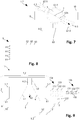
- FIG. 7 shows a device 1.7 for detecting the wire curvature with pivot mechanism and protective device 10.
- the device substantially corresponds to that already in the FIGS. 5a and 5b shown embodiment. Compared to the embodiment of FIGS. 5a and 5b a protective device 10 was added.
- the protection device 10 consists of two three-sided open boxes.
- the swivel unit consisting of swivel arms 62.5 and base 61.5, can as in FIG. 2 be designed shown.
- the three-sided open boxes of the protection device 10 have a side length which is smaller than the distance between the two pivot arms 62.5, and are positioned so that the pivot arms 62.5 are located to the right and left of the boxes when the pivot unit is in the park position.
- In the parking position are the camera 4.5 and, if present, the lighting unit 9.5, inside the boxes.
- the boxes protect the camera 4.5 and the illumination unit 9.5 on three sides.
- the open narrow sides of the box can be covered substantially by the pivot arms 62.5.
- a screen which is directly attached to the camera 4.5 or the lighting unit 9.5 or the support on which these parts are attached, attached and has appropriate dimensions, in the parking position, the remaining, open side of the box substantially cover.
- Camera 4.5 and lighting unit 9.5 can thus be substantially completely protected.
- the boxes can be designed to fit. For example, they may have only one open narrow side or a narrow, central "passage" for a central pivot arm, which lies in the direction of rotation in front of the camera 4.5 or in front of the illumination unit 9.5.
- a central pivot arm can lie behind the camera 4.5 or behind the illumination unit 9.5 in the direction of rotation: a pivot arm arranged in this way does not have to extend into the area of the box and in this case the boxes can only manage with one open side.
- the parking position is horizontal. This alignment is arbitrary.
- the parking position can be any position that can be reached by the swivel unit for camera 4.5 and optionally illumination unit 9.5.
- a protective device It may be, for example, a diaphragm.
- the camera system or the camera 4 whose detector and / or optics are covered and protected by a diaphragm, can be protected from soiling by a housing that covers the remaining areas and parts.
- a parking position is then not given by a camera position, but by the positioning of the aperture.
- a suitable mechanism eg in the form of a filter wheel moves the shutter as a protective device into the parking position and also allows it to leave it again.
- FIG. 8 shows a possible construction of a lighting device 9, which can radiate substantially uniformly over a radiating surface 93 light.
- the lighting device 9 comprises a plurality of small light sources 91. These are mounted on the back of a cavity. At a certain distance from the light sources 91, a first opaque screen 92 is mounted and at a further distance farther from the light sources 91 a second opaque screen 92.
- the radiating surface 93 may also be opaque. Greater distances and more screens and more, small light sources 91 can even more uniformly radiate the uniformly radiating surface 93.
- FIG. 9 shows an embodiment of a device for wire straightening 11: A first part is by a device for detecting the wire curvature 1.2, as already in FIG. 2 and the associated description has been formed.
- the wire 2 passes through the device for detecting the wire curvature 1.2.
- the wire passes two straightening elements 13a and 13b.
- the straightening elements 13a can compensate for a curvature in a second direction and the straightening elements 13b for a curvature in a first direction.
- the guide elements 13a, 13b shown here by way of example each comprise two pairs of wire guide rollers 131 and one pair of wire bending rollers 132 each.
- the pairs of wire bending rollers 132 are each attached to a guide 133.
- These guides 133 are motorized and can be controlled by a directional control element 12.
- the directional element controller 12 is connected to the guides 133 via signal lines 122.
- the directional element controller 12 could also be used to determine and control the rotational speed of all or individual rollers 131, 132, thus producing a propulsion of the wire 2.
- the directional element controller 12 receives data about the measured wire curvature from the data evaluation unit 5.2.
- the data transmission between directional element controller 12 and data evaluation unit 5.2 can be done via a wireless channel 121.
- all other devices according to the invention for detecting the wire curvature can also be connected upstream of the straightening elements 13a and 13b.
- the straightening elements 13a and 13b may also be designed differently: Instead of rollers and edges or electromagnetic forces can be used to direct the wire. Any device for the controlled straightening of wire known to the person skilled in the art can be used in conjunction with a device according to the invention for detecting the wire curvature.
- data is sometimes transmitted wirelessly and in some cases wirelessly.
- a transmission via cable can also be replaced by a wireless transmission and vice versa.
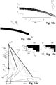
- FIGS. 10a to 10f illustrate the processing steps that the data processing unit 5 performs:
- FIG. 10a shows an illustration of unprocessed image data 14.
- image data 14 is an image of the wire 141, labels and marks 142 and image defects 143.
- Image error 143 for example, by unwanted contamination, defects in optical elements, the detector or reading the data arise.
- Labels and markers 142 may, for example, be mounted on the illumination device 9 and help to associate image data 14 with a viewing direction. Measurements of intensities, colors or lengths can also be simplified or calibrated by markings.
- an image section 15 is cut out.
- the section can preferably be chosen so that as many aberrations and artifacts are outside of the image section 15 and this nevertheless still a long piece of the wire 2 detected.
- FIG. 10b shows the result after the image section 15 has been obtained from the unprocessed image data 14 and the image data has been binarized.
- the binarization of the image data is done by having all data below or equal to a threshold receive a first value 16b and all data above the threshold associated with a second value 16a.
- FIG. 10c shows, for illustrative purposes, only a very small portion of the image data from the image section 15.
- Each pixel 17 is shown here as a box.
- the value of the individual pixel 17 is indicated by its color: white boxes have a first value 16b and black boxes have a second value 16a.
- Direct neighbors 171 of a pixel 17 are all pixels 17 which share a common page or corner with the pixel 17 in question.
- the pixels 17 here all have the same length 172.
- the length of a pixel is preferably its extension in the direction of the wire longitudinal axis of a perfectly straight wire 2 guided in the wire guide 3.
- FIG. 10d illustrates how the shell points 20 are found in known contours 18a and 18b.
- a reference point 19 far away from both contours 18a and 18b, is selected.
- the size of a test area 191 is determined, in particular its length 1911.
- the length 1911 of the test area 191 corresponds approximately to 1.75 times a regular structure of both contours 18a, 18b.
- the distance 192 or 193 to the reference point 19 is determined.
- the first contour 18a that is to say the contour 18 which is closer to the reference point 19
- the smallest distance 193a of all distances 192, 193a of pixels 17 of the contour 18a which lie within the relevant test area 191 is sought.
- the relevant pixel is a hull point 20 of the first contour 18a.
- the test area 191 is shifted by at least the length 172 of a pixel or a multiple thereof and the determination of a skin point 20 is repeated.
- the 181 is the estimated mean distance between the two contours 18a and 18b.
- the average distance between the two contours can be determined, for example, by calculating the distance between the two contours at a randomly selected but sufficiently large number of points.
- the number of pixels could also be counted, which have the second value in the binarized image section and the number divided by the, in number of pixel lengths 172 specified, length of the image section 15.
- the length of the image section 15 can in turn be determined along the longitudinal axis of an ideally straight and clamped in the wire guide 3 wire 2.
- FIG. 10e Finally, a possible result is shown when interpolating between the various envelope points.
- 18a and 18b are the original contours.
- 21a and 21b are the contour envelopes following the interpolation of the envelope points.
- FIG. 10f Three measurement windows 22 each having the same size are defined. The center of area 222 of all pixels 17 is formed, which lie both within the relevant measuring window 22 and between the contours 18a, 18b or the contour envelopes 21a, 21b. This results in a centroid 222 in each of the measurement windows 22.
- a vector 223 is determined which connects the two furthest apart centroids 222. The largest distance 23 of a centroid 222 from this vector 223 is a possible measure of the wire curvature.
- two area centroids 222 define the vector 223, so that the largest distance 23 is at the same time also the only non-trivial distance.
- the three measuring windows 22 are arranged at regular intervals 224a, 224b from each other.
- the exact execution of the wire guide is not important for the choice of the camera system.
- On lighting devices can also be dispensed with.
- the data evaluation unit can be structurally integrated into the device (for example by being inside the pedestal 8 or directly mounted thereon) or it can be a logical integration in which the data evaluation unit is arranged at a different location than the wire guide and the camera system.
- Direction element controller 12 and data evaluation unit 5 can be executed in a computer and even in their logic hardly separable connected to each other or spatially and / or logically completely separate elements.
Landscapes
- Physics & Mathematics (AREA)
- General Physics & Mathematics (AREA)
- Engineering & Computer Science (AREA)
- Mechanical Engineering (AREA)
- Length Measuring Devices By Optical Means (AREA)
Claims (15)
- Arrangement pour détecter une courbure de fil (1), comprenant un guide-fil (3), l'arrangement comprenant en outre les éléments suivants :a) un système de caméra comportant au moins une caméra (4), le système de caméra étant positionné et dimensionné de telle sorte qu'il peut acquérir sous la forme de données d'image un fil (2) passé dans le guide-fil (3) et sa délimitation (22a, 22b) perpendiculairement à un axe longitudinal de fil (21), etb) une unité d'interprétation de données (5) qui est conçue pour recevoir les données d'images du système de caméra et déterminer la courbure de fil à partir de celles-ci,c) caractérisé en ce que l'unité d'interprétation de données (5) est configurée de telle sorte que des contours peuvent être identifiés en déterminant tous les pixels qui possèdent eux-mêmes une valeur supérieure à une valeur de seuil et au moins un voisin ayant une valeur inférieure ou égale à la valeur de seuil et/ou qui possèdent eux-mêmes une valeur inférieure ou égale à la valeur de seuil et au moins un voisin ayant une valeur supérieure à la valeur de seuil.
- Arrangement selon la revendication 1, le système de caméra comportant une caméra (4) et une unité de pivotement (6), l'unité de pivotement (6) comportant un bras pivotant (62) et une partie de base (61) et la caméra (4) étant fixée au bras pivotant (62), lequel peut pivoter par rapport à la partie de base (61) et la caméra (4), par un pivotement du bras pivotant (62), pouvant atteindre une première et une deuxième position dans lesquelles la caméra (4) peut acquérir sous la forme de données d'image un fil (2) passé dans le guide-fil (3) et sa délimitation (22a, 22b) perpendiculairement à un axe longitudinal de fil (21) et la caméra (4), dans la première et la deuxième position, possédant respectivement une direction de visée (42a, b) différente et la direction de visée (42a, b) de la caméra (4) dans la première et la deuxième position incluant un angle (43) supérieur à 0°, de préférence un angle (43) entre 45° et 90°, notamment de préférence un angle (45) de 90°.
- Arrangement selon la revendication 2, un axe autour duquel le bras pivotant (62) peut pivoter par rapport à la partie de base (61) étant sensiblement égal à l'axe qui correspond à l'axe longitudinal (21) d'un fil (2) passé dans le guide-fil (3), notamment dans la zone du guide-fil (3).
- Arrangement selon l'une des revendications 1 à 3, comprenant un dispositif d'éclairage (9), le dispositif d'éclairage (9) étant notamment disposé de telle sorte qu'il peut émettre de la lumière dans une direction de visée (42) inverse d'une caméra (4) du système de caméra.
- Arrangement selon l'une des revendications 2 à 3, un dispositif d'éclairage (9) étant fixé au bras pivotant (62), et ce notamment de telle sorte qu'il peut émettre de la lumière dans une direction de visée (42) inverse de la caméra (4) fixée au bras pivotant.
- Arrangement selon l'une des revendications 1 à 5, caractérisé par un arrangement de protection (10) pour l'au moins une caméra (4) du système de caméra et notamment pour le dispositif d'éclairage (9) selon les revendications 4 ou 5, l'arrangement de protection (10) étant notamment configuré de telle sorte que l'au moins une caméra (4) et le dispositif d'éclairage (9) sont, dans une position de stationnement, protégés contre un encrassement par des particules volantes, l'arrangement de protection (10) comportant notamment des écrans ou des coffrets ouverts d'un côté ou de deux côtés et, dans la position de stationnement, l'au moins une caméra (4) du système de caméra ne pouvant de préférence acquérir aucune donnée d'image d'un fil (2) passé dans le guide-fil (3) et ses délimitations (22a, 22b).
- Arrangement selon l'une des revendications 1 à 6, dans lequel l'unité d'interprétation de données (5) est configurée de telle sorte qu'elle peut exécuter l'étape suivante :a) découper les données d'image (14) sur une portion prédéfinie souhaitée, de sorte qu'il en résulte une portion d'image (15).
- Arrangement selon l'une des revendications 1 à 7, dans lequel l'unité d'interprétation de données (5) est en outre configurée de telle sorte qu'elle peut exécuter les étapes suivantes :a) définition d'un point de référence virtuel (19) lointain, celui-ci étant de préférence éloigné de plus du décuple de l'écart moyen (181) entre le premier et le deuxième contour (18a, b) de chacun des contours (18a, b) ;b) en partant d'une extrémité d'un premier contour (18a), déterminer à présent, pour tous les pixels qui appartiennent au premier contour et se trouvent à l'intérieur d'une zone de test (191) ayant une longueur fixe (1911) prédéfinie, l'écart (192) par rapport au point de référence virtuel (19) ;c) acquisition du pixel (17) du premier contour (18a) à l'intérieur de la zone de test (191) qui présente le plus petit écart (193a) par rapport au point de référence virtuel (19) en tant que point d'enveloppe (20) ;d) décalage de la zone de test (191) dans sa direction longitudinale, notamment d'une longueur qui est égale ou supérieure à une longueur de l'un des pixels (172) et inférieure ou égale à la longueur (1911) de la zone de test (191), de préférence d'une longueur égale à la longueur de l'un des pixels (172) ;e) répétition des alinéas b), c) et d) jusqu'à ce que le premier contour (18a) soit entièrement échantillonné ;f) exécution similaire des étapes b) à e) avec le deuxième contour (18b) au lieu du premier (18a), le plus grand écart (193b) par rapport au point de référence virtuel (19), au lieu du plus petit, étant de préférence utilisé à l'étape c) pour l'acquisition d'un point d'enveloppe (20) ;g) interpolation des points d'enveloppe (20) du premier contour (18a) en une première enveloppe de contour (21a) ; eth) interpolation des points d'enveloppe (20) du deuxième contour (18b) en une deuxième enveloppe de contour (21b).
- Arrangement selon l'une des revendications 1 à 8, dans lequel l'unité d'interprétation de données (5) est configurée de telle sorte qu'elle peut constater une courbure dans un plan, ena) définissant trois fenêtres de mesure (22) rectangulaires de même taille, avec lesquelles les deux contours (18a, b) ou les enveloppes de contour (21a, b) passent respectivement à travers toutes les lignes latérales parallèles les unes aux autres et les fenêtres de mesure (22) étant positionnées en trois emplacements différents le long des contours (18a, b) ou des enveloppes de contour (21a, b) ;b) déterminant, respectivement à l'intérieur de chacune des fenêtres de mesure, un barycentre de surface (222) de tous les pixels (221) qui se trouvent entre le premier et le deuxième contour (18a, b) ou l'enveloppe de contour (21a, b) ;c) déterminant un vecteur (223) qui relie les deux barycentres de surface (222) les plus éloignés l'un de l'autre ; etd) déterminant le plus grand écart (23) entre un barycentre de surface (222) et le vecteur (223) en tant que mesure pour une courbure, notamment une courbure de fil dans un plan.
- Arrangement selon la revendication 9, dans lequel l'unité d'interprétation de données (5) est conçue poura) à partir de premières données d'image, générées par une caméra (4) dans une première position ou une première caméra (4a),b) déterminer une première courbure dans un premier plan parallèle au plan normal de la direction de visée (42a) de la première caméra (4a) ou de la première position de la caméra (4) etc) à partir de deuxièmes données d'image, générées par une caméra (4) dans une deuxième position ou une deuxième caméra (4b),d) déterminer une deuxième courbure dans un deuxième plan parallèle au plan normal de la direction de visée (42b) de la deuxième caméra (4b) ou de la deuxième position de la caméra (4) ete) utiliser la première et la deuxième courbure ainsi que des informations à propos de la position des directions de visée (42a, b) l'une par rapport à l'autre et/ou notamment la position des directions de visée (42a, b) par rapport à un espace de référence commun afin de déterminer une courbure dans trois dimensions spatiales et/ou notamment par rapport à l'espace de référence.
- Unité de dressage de fil (11), comportanta) un arrangement (1) pour détecter une courbure de fil selon l'une des revendications 1 à 10 etb) une commande d'élément de dressage (12) qui reçoit des données à propos d'une courbure de fil détectée par l'arrangement (1) et les interprète de telle sorte qu'ellec) peut positionner et/ou commander des éléments de dressage (13a, b) en fonction des données de sorte que la courbure de fil, notamment détectée par l'arrangement (1), peut être au moins partiellement compensée.
- Procédé de détermination de la courbure de fil, comprenant les étapes suivantes :a) positionnement d'un fil (2) dans un arrangement pour détecter une courbure de fil (1) selon l'une des revendications 1 à 10 ;b) acquisition de données d'image du fil (2) par le système de caméra ;c) communication des données d'image à l'unité d'interprétation de données (5) ;d) interprétation des données d'image en vue de détecter la courbure de fil par l'unité d'interprétation de données (5) et notamment par un programme d'interprétation de données exécutable par l'unité d'interprétation de données (5).
- Procédé de dressage de fil, comprenanta) le procédé de détermination de la courbure de fil selon la revendication 12 ;b) communication de la courbure de fil à une commande d'élément de dressage (12) ; etc) positionnement et/ou commande d'éléments de dressage (13a, b) en fonction de la courbure de fil communiquée de manière à contrer au moins partiellement la courbure de fil mesurée.
- Procédé de dressage de fil, le procédé selon la revendication 13 étant répété plusieurs fois avec le même fil (2).
- Procédé de détermination de la courbure de fil, le procédé selon la revendication 12 étant répété plusieurs fois avec le même fil (2).
Priority Applications (1)
| Application Number | Priority Date | Filing Date | Title |
|---|---|---|---|
| EP17150289.1A EP3346230B1 (fr) | 2017-01-04 | 2017-01-04 | Dispositif et procede de mesure de la courbure d'un fil |
Applications Claiming Priority (1)
| Application Number | Priority Date | Filing Date | Title |
|---|---|---|---|
| EP17150289.1A EP3346230B1 (fr) | 2017-01-04 | 2017-01-04 | Dispositif et procede de mesure de la courbure d'un fil |
Publications (2)
| Publication Number | Publication Date |
|---|---|
| EP3346230A1 EP3346230A1 (fr) | 2018-07-11 |
| EP3346230B1 true EP3346230B1 (fr) | 2019-08-28 |
Family
ID=57749830
Family Applications (1)
| Application Number | Title | Priority Date | Filing Date |
|---|---|---|---|
| EP17150289.1A Active EP3346230B1 (fr) | 2017-01-04 | 2017-01-04 | Dispositif et procede de mesure de la courbure d'un fil |
Country Status (1)
| Country | Link |
|---|---|
| EP (1) | EP3346230B1 (fr) |
Families Citing this family (11)
| Publication number | Priority date | Publication date | Assignee | Title |
|---|---|---|---|---|
| CN109141297B (zh) * | 2018-08-31 | 2020-07-24 | 淮南文峰航天电缆有限公司 | 一种电缆检测装置 |
| CN109244904B (zh) * | 2018-09-20 | 2020-02-11 | 国家电网公司 | 一种变电站二次接线拉直折弯装置及导线固定松紧调试方法 |
| EP3930936B1 (fr) | 2019-02-25 | 2023-12-20 | Schnell S.p.A. | Procédé et appareil de détection de la courbure d'éléments métalliques allongés |
| DE102019206619B4 (de) * | 2019-05-08 | 2022-03-17 | Wafios Aktiengesellschaft | Messverfahren und Messvorrichtung zum Messen der Geradheit von Rundmaterialstücken |
| IT202000001957A1 (it) * | 2020-01-31 | 2021-07-31 | Microstudio S R L | Strumento e metodo per caratterizzare un oggetto in filo sagomato |
| CN112080956A (zh) * | 2020-08-03 | 2020-12-15 | 马鞍山市顺泰稀土新材料有限公司 | 一种用于厚锌层镀锌钢绞线的应力消除设备 |
| DE102021212056A1 (de) | 2021-10-26 | 2023-04-27 | Wafios Aktiengesellschaft | Messeinheit und Messverfahren zum Messen von gerichtetem draht- oder rohrförmigen Richtgut |
| CN114942615B (zh) * | 2022-05-23 | 2023-07-28 | 江南大学 | 一种等弓高误差插补方法、装置及存储介质 |
| DE102022210293A1 (de) * | 2022-09-28 | 2024-03-28 | Felsomat Gmbh & Co. Kg | Verfahren und Fertigungsanlage zum Herstellen von Stableitern |
| DE102023126784A1 (de) | 2023-10-02 | 2025-04-03 | Wafios Aktiengesellschaft | Verfahren und System zum Einrichten eines Richtsystems |
| CN121498596A (zh) * | 2026-01-13 | 2026-02-10 | 江苏腾驰科技有限公司 | 一种弯管角度检测装置及其检测方法 |
Family Cites Families (4)
| Publication number | Priority date | Publication date | Assignee | Title |
|---|---|---|---|---|
| US5685186A (en) * | 1993-12-29 | 1997-11-11 | Bausch & Lomb Incorporated | Base curve bender |
| DE19503850C1 (de) | 1995-02-06 | 1996-06-13 | Post Friedhelm Sondermasch | Nichtrotierender Richtapparat für Biegemaschinen mit integrierter Meßvorrichtung |
| US7110910B1 (en) * | 2005-06-13 | 2006-09-19 | The Timken Company | Method and apparatus for determining the straightness of tubes and bars |
| DE102006028102A1 (de) | 2006-06-19 | 2007-12-20 | Siemens Ag | Abhaspeleinrichtung |
-
2017
- 2017-01-04 EP EP17150289.1A patent/EP3346230B1/fr active Active
Non-Patent Citations (1)
| Title |
|---|
| None * |
Also Published As
| Publication number | Publication date |
|---|---|
| EP3346230A1 (fr) | 2018-07-11 |
Similar Documents
| Publication | Publication Date | Title |
|---|---|---|
| EP3346230B1 (fr) | Dispositif et procede de mesure de la courbure d'un fil | |
| EP3557523B1 (fr) | Procédé de génération d'un modèle de correction d'une caméra permettant de corriger une erreur d'image | |
| DE10291985B4 (de) | Verfahren und Vorrichtung zur berührungsfreien Untersuchung eines Gegenstandes, insbesondere hinsichtlich dessen Oberflächengestalt | |
| DE3822303C2 (fr) | ||
| DE3587482T2 (de) | Fehlerinspektion fuer plattenoberflaechen. | |
| EP0932816B1 (fr) | Procede et dispositif pour mesurer le trace de surfaces reflechissantes | |
| DE69207176T2 (de) | Optischer Sensor | |
| EP2511648B1 (fr) | Agencement de mesure et procédé de détermination d'au moins une hauteur de sertissage d'un sertissage de conducteur | |
| DE112006001820T5 (de) | Optimieren der Verwendung und Leistung von optischen Systemen, die mit telezentrischer Dunkelfeldbeleuchtung auf der Achse implementiert werden | |
| EP4046133B1 (fr) | Procédé et dispositif de détermination d'un contour d'une rainure de monture | |
| DE102008036275B4 (de) | Verfahren zum Vermessen von Profilen mit optischen Sensoren | |
| EP3017273A1 (fr) | Procédé et dispositif de détection optique de la forme d'un objet et/ou de contrôle optique d'un objet | |
| EP1567827A1 (fr) | Procede et dispositif de mesure de forme et/ou d'evaluation par voie optique | |
| DE102015201823B4 (de) | Vorrichtung und Verfahren zur automatisierten Klassifizierung der Güte von Werkstücken | |
| DE102015011427B4 (de) | Bildaufnahmesystem und Bildauswertesystem | |
| EP1864081A1 (fr) | Dispositif pour detecter optiquement la forme d'objets et de surfaces | |
| EP4630776A1 (fr) | Dispositif et procédé de détermination de qualité d'imagerie d'au moins une image pour un élément d'inspection | |
| DE3831267A1 (de) | Optischer messfuehler | |
| DE102011001289B4 (de) | Vorrichtung zur optischen Erfassung von Prüfobjekten | |
| DE102013208397B4 (de) | Koordinatenmessgerät mit einem zusätzlichen, berührungslos messenden Oberflächenvermessungsgerät | |
| DE102008036264A1 (de) | Optischer Sensor und Verfahren zum Vermessen von Profilen | |
| EP0848810A1 (fr) | Procede et dispositif de mesure des proprietes optiques de verres de lunettes au moyen d'un detecteur optique de dessins graves dans les verres de lunettes | |
| DE19709050A1 (de) | Anordnung zur bildhaften, farblichen Erfassung von räumlichen Gegenständen mit einem Flachbettscanner | |
| WO2016071078A2 (fr) | Mesure de la topographie et/ou du gradient et/ou de la courbure d'une surface d'un verre de lunettes réfléchissant la lumière | |
| DE102008031412A1 (de) | Vorrichtung und Verfahren zur Beobachtung mehrerer auf einer Linie angeordneter Messpunkte auf einer zu vermessenden Objektoberfläche |
Legal Events
| Date | Code | Title | Description |
|---|---|---|---|
| PUAI | Public reference made under article 153(3) epc to a published international application that has entered the european phase |
Free format text: ORIGINAL CODE: 0009012 |
|
| STAA | Information on the status of an ep patent application or granted ep patent |
Free format text: STATUS: THE APPLICATION HAS BEEN PUBLISHED |
|
| AK | Designated contracting states |
Kind code of ref document: A1 Designated state(s): AL AT BE BG CH CY CZ DE DK EE ES FI FR GB GR HR HU IE IS IT LI LT LU LV MC MK MT NL NO PL PT RO RS SE SI SK SM TR |
|
| AX | Request for extension of the european patent |
Extension state: BA ME |
|
| STAA | Information on the status of an ep patent application or granted ep patent |
Free format text: STATUS: REQUEST FOR EXAMINATION WAS MADE |
|
| 17P | Request for examination filed |
Effective date: 20181217 |
|
| RBV | Designated contracting states (corrected) |
Designated state(s): AL AT BE BG CH CY CZ DE DK EE ES FI FR GB GR HR HU IE IS IT LI LT LU LV MC MK MT NL NO PL PT RO RS SE SI SK SM TR |
|
| GRAP | Despatch of communication of intention to grant a patent |
Free format text: ORIGINAL CODE: EPIDOSNIGR1 |
|
| STAA | Information on the status of an ep patent application or granted ep patent |
Free format text: STATUS: GRANT OF PATENT IS INTENDED |
|
| INTG | Intention to grant announced |
Effective date: 20190423 |
|
| GRAS | Grant fee paid |
Free format text: ORIGINAL CODE: EPIDOSNIGR3 |
|
| GRAA | (expected) grant |
Free format text: ORIGINAL CODE: 0009210 |
|
| STAA | Information on the status of an ep patent application or granted ep patent |
Free format text: STATUS: THE PATENT HAS BEEN GRANTED |
|
| AK | Designated contracting states |
Kind code of ref document: B1 Designated state(s): AL AT BE BG CH CY CZ DE DK EE ES FI FR GB GR HR HU IE IS IT LI LT LU LV MC MK MT NL NO PL PT RO RS SE SI SK SM TR |
|
| REG | Reference to a national code |
Ref country code: GB Ref legal event code: FG4D Free format text: NOT ENGLISH |
|
| REG | Reference to a national code |
Ref country code: CH Ref legal event code: EP |
|
| REG | Reference to a national code |
Ref country code: AT Ref legal event code: REF Ref document number: 1172958 Country of ref document: AT Kind code of ref document: T Effective date: 20190915 |
|
| REG | Reference to a national code |
Ref country code: IE Ref legal event code: FG4D Free format text: LANGUAGE OF EP DOCUMENT: GERMAN |
|
| REG | Reference to a national code |
Ref country code: DE Ref legal event code: R096 Ref document number: 502017002105 Country of ref document: DE |
|
| REG | Reference to a national code |
Ref country code: CH Ref legal event code: NV Representative=s name: KELLER AND PARTNER PATENTANWAELTE AG, CH |
|
| REG | Reference to a national code |
Ref country code: NL Ref legal event code: MP Effective date: 20190828 |
|
| REG | Reference to a national code |
Ref country code: LT Ref legal event code: MG4D |
|
| PG25 | Lapsed in a contracting state [announced via postgrant information from national office to epo] |
Ref country code: PT Free format text: LAPSE BECAUSE OF FAILURE TO SUBMIT A TRANSLATION OF THE DESCRIPTION OR TO PAY THE FEE WITHIN THE PRESCRIBED TIME-LIMIT Effective date: 20191230 Ref country code: FI Free format text: LAPSE BECAUSE OF FAILURE TO SUBMIT A TRANSLATION OF THE DESCRIPTION OR TO PAY THE FEE WITHIN THE PRESCRIBED TIME-LIMIT Effective date: 20190828 Ref country code: NO Free format text: LAPSE BECAUSE OF FAILURE TO SUBMIT A TRANSLATION OF THE DESCRIPTION OR TO PAY THE FEE WITHIN THE PRESCRIBED TIME-LIMIT Effective date: 20191128 Ref country code: SE Free format text: LAPSE BECAUSE OF FAILURE TO SUBMIT A TRANSLATION OF THE DESCRIPTION OR TO PAY THE FEE WITHIN THE PRESCRIBED TIME-LIMIT Effective date: 20190828 Ref country code: LT Free format text: LAPSE BECAUSE OF FAILURE TO SUBMIT A TRANSLATION OF THE DESCRIPTION OR TO PAY THE FEE WITHIN THE PRESCRIBED TIME-LIMIT Effective date: 20190828 Ref country code: NL Free format text: LAPSE BECAUSE OF FAILURE TO SUBMIT A TRANSLATION OF THE DESCRIPTION OR TO PAY THE FEE WITHIN THE PRESCRIBED TIME-LIMIT Effective date: 20190828 Ref country code: HR Free format text: LAPSE BECAUSE OF FAILURE TO SUBMIT A TRANSLATION OF THE DESCRIPTION OR TO PAY THE FEE WITHIN THE PRESCRIBED TIME-LIMIT Effective date: 20190828 Ref country code: BG Free format text: LAPSE BECAUSE OF FAILURE TO SUBMIT A TRANSLATION OF THE DESCRIPTION OR TO PAY THE FEE WITHIN THE PRESCRIBED TIME-LIMIT Effective date: 20191128 |
|
| PG25 | Lapsed in a contracting state [announced via postgrant information from national office to epo] |
Ref country code: AL Free format text: LAPSE BECAUSE OF FAILURE TO SUBMIT A TRANSLATION OF THE DESCRIPTION OR TO PAY THE FEE WITHIN THE PRESCRIBED TIME-LIMIT Effective date: 20190828 Ref country code: LV Free format text: LAPSE BECAUSE OF FAILURE TO SUBMIT A TRANSLATION OF THE DESCRIPTION OR TO PAY THE FEE WITHIN THE PRESCRIBED TIME-LIMIT Effective date: 20190828 Ref country code: RS Free format text: LAPSE BECAUSE OF FAILURE TO SUBMIT A TRANSLATION OF THE DESCRIPTION OR TO PAY THE FEE WITHIN THE PRESCRIBED TIME-LIMIT Effective date: 20190828 Ref country code: IS Free format text: LAPSE BECAUSE OF FAILURE TO SUBMIT A TRANSLATION OF THE DESCRIPTION OR TO PAY THE FEE WITHIN THE PRESCRIBED TIME-LIMIT Effective date: 20191228 Ref country code: GR Free format text: LAPSE BECAUSE OF FAILURE TO SUBMIT A TRANSLATION OF THE DESCRIPTION OR TO PAY THE FEE WITHIN THE PRESCRIBED TIME-LIMIT Effective date: 20191129 Ref country code: ES Free format text: LAPSE BECAUSE OF FAILURE TO SUBMIT A TRANSLATION OF THE DESCRIPTION OR TO PAY THE FEE WITHIN THE PRESCRIBED TIME-LIMIT Effective date: 20190828 |
|
| PG25 | Lapsed in a contracting state [announced via postgrant information from national office to epo] |
Ref country code: TR Free format text: LAPSE BECAUSE OF FAILURE TO SUBMIT A TRANSLATION OF THE DESCRIPTION OR TO PAY THE FEE WITHIN THE PRESCRIBED TIME-LIMIT Effective date: 20190828 |
|
| PG25 | Lapsed in a contracting state [announced via postgrant information from national office to epo] |
Ref country code: DK Free format text: LAPSE BECAUSE OF FAILURE TO SUBMIT A TRANSLATION OF THE DESCRIPTION OR TO PAY THE FEE WITHIN THE PRESCRIBED TIME-LIMIT Effective date: 20190828 Ref country code: PL Free format text: LAPSE BECAUSE OF FAILURE TO SUBMIT A TRANSLATION OF THE DESCRIPTION OR TO PAY THE FEE WITHIN THE PRESCRIBED TIME-LIMIT Effective date: 20190828 Ref country code: EE Free format text: LAPSE BECAUSE OF FAILURE TO SUBMIT A TRANSLATION OF THE DESCRIPTION OR TO PAY THE FEE WITHIN THE PRESCRIBED TIME-LIMIT Effective date: 20190828 Ref country code: RO Free format text: LAPSE BECAUSE OF FAILURE TO SUBMIT A TRANSLATION OF THE DESCRIPTION OR TO PAY THE FEE WITHIN THE PRESCRIBED TIME-LIMIT Effective date: 20190828 |
|
| REG | Reference to a national code |
Ref country code: DE Ref legal event code: R082 Ref document number: 502017002105 Country of ref document: DE Representative=s name: PATENTANWAELTE OLBRICHT, BUCHHOLD, KEULERTZ PA, DE |
|
| PG25 | Lapsed in a contracting state [announced via postgrant information from national office to epo] |
Ref country code: CZ Free format text: LAPSE BECAUSE OF FAILURE TO SUBMIT A TRANSLATION OF THE DESCRIPTION OR TO PAY THE FEE WITHIN THE PRESCRIBED TIME-LIMIT Effective date: 20190828 Ref country code: SM Free format text: LAPSE BECAUSE OF FAILURE TO SUBMIT A TRANSLATION OF THE DESCRIPTION OR TO PAY THE FEE WITHIN THE PRESCRIBED TIME-LIMIT Effective date: 20190828 Ref country code: SK Free format text: LAPSE BECAUSE OF FAILURE TO SUBMIT A TRANSLATION OF THE DESCRIPTION OR TO PAY THE FEE WITHIN THE PRESCRIBED TIME-LIMIT Effective date: 20190828 Ref country code: IS Free format text: LAPSE BECAUSE OF FAILURE TO SUBMIT A TRANSLATION OF THE DESCRIPTION OR TO PAY THE FEE WITHIN THE PRESCRIBED TIME-LIMIT Effective date: 20200224 |
|
| REG | Reference to a national code |
Ref country code: DE Ref legal event code: R097 Ref document number: 502017002105 Country of ref document: DE |
|
| PLBE | No opposition filed within time limit |
Free format text: ORIGINAL CODE: 0009261 |
|
| STAA | Information on the status of an ep patent application or granted ep patent |
Free format text: STATUS: NO OPPOSITION FILED WITHIN TIME LIMIT |
|
| PG2D | Information on lapse in contracting state deleted |
Ref country code: IS |
|
| 26N | No opposition filed |
Effective date: 20200603 |
|
| PG25 | Lapsed in a contracting state [announced via postgrant information from national office to epo] |
Ref country code: SI Free format text: LAPSE BECAUSE OF FAILURE TO SUBMIT A TRANSLATION OF THE DESCRIPTION OR TO PAY THE FEE WITHIN THE PRESCRIBED TIME-LIMIT Effective date: 20190828 Ref country code: MC Free format text: LAPSE BECAUSE OF FAILURE TO SUBMIT A TRANSLATION OF THE DESCRIPTION OR TO PAY THE FEE WITHIN THE PRESCRIBED TIME-LIMIT Effective date: 20190828 |
|
| REG | Reference to a national code |
Ref country code: CH Ref legal event code: PFA Owner name: SCHLATTER INDUSTRIES AG, CH Free format text: FORMER OWNER: SCHLATTER INDUSTRIES AG, CH |
|
| REG | Reference to a national code |
Ref country code: BE Ref legal event code: MM Effective date: 20200131 |
|
| PG25 | Lapsed in a contracting state [announced via postgrant information from national office to epo] |
Ref country code: FR Free format text: LAPSE BECAUSE OF NON-PAYMENT OF DUE FEES Effective date: 20200131 Ref country code: LU Free format text: LAPSE BECAUSE OF NON-PAYMENT OF DUE FEES Effective date: 20200104 |
|
| PG25 | Lapsed in a contracting state [announced via postgrant information from national office to epo] |
Ref country code: BE Free format text: LAPSE BECAUSE OF NON-PAYMENT OF DUE FEES Effective date: 20200131 |
|
| PG25 | Lapsed in a contracting state [announced via postgrant information from national office to epo] |
Ref country code: IE Free format text: LAPSE BECAUSE OF NON-PAYMENT OF DUE FEES Effective date: 20200104 |
|
| GBPC | Gb: european patent ceased through non-payment of renewal fee |
Effective date: 20210104 |
|
| PG25 | Lapsed in a contracting state [announced via postgrant information from national office to epo] |
Ref country code: GB Free format text: LAPSE BECAUSE OF NON-PAYMENT OF DUE FEES Effective date: 20210104 |
|
| PG25 | Lapsed in a contracting state [announced via postgrant information from national office to epo] |
Ref country code: MT Free format text: LAPSE BECAUSE OF FAILURE TO SUBMIT A TRANSLATION OF THE DESCRIPTION OR TO PAY THE FEE WITHIN THE PRESCRIBED TIME-LIMIT Effective date: 20190828 Ref country code: CY Free format text: LAPSE BECAUSE OF FAILURE TO SUBMIT A TRANSLATION OF THE DESCRIPTION OR TO PAY THE FEE WITHIN THE PRESCRIBED TIME-LIMIT Effective date: 20190828 |
|
| PG25 | Lapsed in a contracting state [announced via postgrant information from national office to epo] |
Ref country code: MK Free format text: LAPSE BECAUSE OF FAILURE TO SUBMIT A TRANSLATION OF THE DESCRIPTION OR TO PAY THE FEE WITHIN THE PRESCRIBED TIME-LIMIT Effective date: 20190828 |
|
| REG | Reference to a national code |
Ref country code: DE Ref legal event code: R082 Ref document number: 502017002105 Country of ref document: DE Representative=s name: PATENTANWAELTE OLBRICHT, BUCHHOLD, KEULERTZ PA, DE |
|
| P01 | Opt-out of the competence of the unified patent court (upc) registered |
Effective date: 20230515 |
|
| REG | Reference to a national code |
Ref country code: CH Ref legal event code: U11 Free format text: ST27 STATUS EVENT CODE: U-0-0-U10-U11 (AS PROVIDED BY THE NATIONAL OFFICE) Effective date: 20260201 |
|
| PGFP | Annual fee paid to national office [announced via postgrant information from national office to epo] |
Ref country code: DE Payment date: 20260121 Year of fee payment: 10 |
|
| PGFP | Annual fee paid to national office [announced via postgrant information from national office to epo] |
Ref country code: AT Payment date: 20260122 Year of fee payment: 10 |
|
| PGFP | Annual fee paid to national office [announced via postgrant information from national office to epo] |
Ref country code: IT Payment date: 20260126 Year of fee payment: 10 |
|
| PGFP | Annual fee paid to national office [announced via postgrant information from national office to epo] |
Ref country code: CH Payment date: 20260201 Year of fee payment: 10 |