EP3346231B1 - Dispositif de mesure de forme de surface, méthode et programme de mesure de forme de surface - Google Patents
Dispositif de mesure de forme de surface, méthode et programme de mesure de forme de surface Download PDFInfo
- Publication number
- EP3346231B1 EP3346231B1 EP16841905.9A EP16841905A EP3346231B1 EP 3346231 B1 EP3346231 B1 EP 3346231B1 EP 16841905 A EP16841905 A EP 16841905A EP 3346231 B1 EP3346231 B1 EP 3346231B1
- Authority
- EP
- European Patent Office
- Prior art keywords
- measurement
- distance
- surface shape
- shape
- measurement device
- Prior art date
- Legal status (The legal status is an assumption and is not a legal conclusion. Google has not performed a legal analysis and makes no representation as to the accuracy of the status listed.)
- Active
Links
Images







Classifications
-
- G—PHYSICS
- G01—MEASURING; TESTING
- G01B—MEASURING LENGTH, THICKNESS OR SIMILAR LINEAR DIMENSIONS; MEASURING ANGLES; MEASURING AREAS; MEASURING IRREGULARITIES OF SURFACES OR CONTOURS
- G01B11/00—Measuring arrangements characterised by the use of optical techniques
- G01B11/24—Measuring arrangements characterised by the use of optical techniques for measuring contours or curvatures
- G01B11/2441—Measuring arrangements characterised by the use of optical techniques for measuring contours or curvatures using interferometry
-
- G—PHYSICS
- G01—MEASURING; TESTING
- G01B—MEASURING LENGTH, THICKNESS OR SIMILAR LINEAR DIMENSIONS; MEASURING ANGLES; MEASURING AREAS; MEASURING IRREGULARITIES OF SURFACES OR CONTOURS
- G01B11/00—Measuring arrangements characterised by the use of optical techniques
- G01B11/002—Measuring arrangements characterised by the use of optical techniques for measuring two or more coordinates
- G01B11/005—Measuring arrangements characterised by the use of optical techniques for measuring two or more coordinates coordinate measuring machines
-
- G—PHYSICS
- G01—MEASURING; TESTING
- G01B—MEASURING LENGTH, THICKNESS OR SIMILAR LINEAR DIMENSIONS; MEASURING ANGLES; MEASURING AREAS; MEASURING IRREGULARITIES OF SURFACES OR CONTOURS
- G01B11/00—Measuring arrangements characterised by the use of optical techniques
- G01B11/26—Measuring arrangements characterised by the use of optical techniques for measuring angles or tapers; for testing the alignment of axes
-
- G—PHYSICS
- G01—MEASURING; TESTING
- G01B—MEASURING LENGTH, THICKNESS OR SIMILAR LINEAR DIMENSIONS; MEASURING ANGLES; MEASURING AREAS; MEASURING IRREGULARITIES OF SURFACES OR CONTOURS
- G01B5/00—Measuring arrangements characterised by the use of mechanical techniques
- G01B5/0002—Arrangements for supporting, fixing or guiding the measuring instrument or the object to be measured
- G01B5/0004—Supports
Definitions
- the present invention relates to a surface shape measurement apparatus and a surface shape measurement program.
- Patent Document 1 For a contactless three-dimensional shape measurement device using probe light, a scanning path for a measurement head has been prespecified based on designed shape data of a measurement object such that the probe light is incident on a measurement surface as orthogonally as possible (see Japanese Patent Application Publication No. Hei. 11-51624 , hereinafter Patent Document 1, for example).
- DD 10 2012 111008 A1 discloses an optical measuring device in which distance to each of a triangular spot array of measurement points is obtained, and local inclination of the measurement object surface is inferred therefrom.
- JP 2014 126381 A , US 4 660 970 A , JP 2012 093225 A , JP 2003 161615 A and WO 2014185133A1 forms part of the state of the art.
- a surface shape measurement apparatus as recited in Claim 1.
- the detailed shape data may have a higher precision than the reference shape data.
- It may include a support which supports the distance measurement device and the angle measurement device. It may include a driving part which moves the support relative to the measurement object. It may include a control part which controls the driving part. When measuring the inclination by the angle measurement device, the control part may cause the support to scan by the driving part such that the support opposes a tangent plane at the measurement point calculated from the reference shape data and a distance from the measurement point is constant.
- the measurement object at least partially may have a substantially rotationally symmetric shape, and a target for measurement may be a surface shape of a rotationally symmetric surface. It may include a stage which supports the measurement object. It may include an actuation part which rotationally moves the stage around an axis parallel to a rotational symmetry axis of the rotationally symmetric surface. When measuring the distance by the distance measurement device and measuring the inclination by the angle measurement device, the stage may be rotationally moved by the actuation part.
- the second calculation part may calculate an error amount of a placement error of the measurement object relative to the stage due to deviation between the rotational symmetry axis of the measurement object and a rotation axis of rotational movement of the stage. It may calculate the detailed shape data using the reference shape data modified in consideration of the error amount and an output of the angle measurement device.
- the second calculation part may recalculate the error amount using the detailed shape data temporarily obtained. It may further recompute the detailed shape data based on the recalculated error amount.
- a support which supports the distance measurement device and the angle measurement device may be caused to scan such that the support opposes a tangent plane at the measurement point calculated from the reference shape data and a distance from the measurement point is constant.
- Fig. 1 is an overview showing the entirety of a surface shape measurement apparatus 10 in accordance with the present embodiment.
- the surface shape measurement apparatus 10 is an apparatus which is dedicated to a rotationally symmetric surface as its measurement target and strictly measures a surface shape.
- the surface shape measurement apparatus 10 includes a base 100 as a base table part, and a first frame 140 and a second frame 150 which are securely fixed to the base 100. Each component of the surface shape measurement apparatus 10 related to sensing is assembled directly or indirectly to any of the base 100, the first frame 140 and the second frame 150.
- the upper surface of the base 100 is a horizontal plane, and an axis in the horizontal plane is defined as an x-axis and an axis in the horizontal plane and orthogonal to the x-axis is defined as a y-axis. Also, a z-axis is defined in a vertical direction orthogonal to the horizontal plane. Also, the upward vertical direction is defined as a positive z-axis direction. Note that each subsequent figure clearly shows which direction the figure is observed in with respect to the x-y-z coordinate system shown in Fig. 1 in accordance with the above definitions.
- An X-Y stage 160 is stacked on the upper surface of the base 100, and the X-Y stage 160 can parallelly move in x-y directions on the upper surface of the base 100 and also rotationally move around the z-axis. Note that, in the subsequent descriptions, rotational movement around the z-axis may be referred to as rotation in a ⁇ z direction or the like.
- the X-Y stage 160 has a function as a table on which a measurement object 200 is placed, and fixes the measurement object 200 via a chuck 161.
- the measurement object 200 includes a measurement surface 201 and a holding part 202, and the chuck 161 clamps the holding part 202.
- the measurement surface 201 as a measurement target is a substantially rotationally symmetric surface having a rotational symmetry axis parallel to the z-axis in the attitude of Fig. 1 .
- the substantially rotationally symmetric surface does not refer to the exact rotationally symmetric surface, but refers to a surface in which minute unevenness exists in an asymmetric manner.
- the surface shape measurement apparatus 10 in accordance with the present embodiment is an apparatus which measures a measurement surface, which is a rotationally symmetric surface as a whole but has minute unevenness that is unevenly distributed therein as observed in a locally enlarged view, to acquire more precise surface shape information including information of the shape of such unevenness.
- the measurement surface 201 is a substantially rotationally symmetric surface whose designed shape data is unknown, in particular.
- the measurement object 200 is placed on the X-Y stage 160 such that the rotational symmetry axis of the measurement surface 201 and the axis of rotation of the X-Y stage 160 in the ⁇ z direction coincide with each other.
- the measurement surface 201 of the measurement object 200 placed in this manner is rotationally moved around the rotational symmetry axis, and its surface shape is measured.
- the first frame 140 is a supporting frame established vertically in the z-axis direction from the base 100.
- the first frame 140 supports the second support 130 above its y-z surface, and the second support 130 supports the first support 120 on a surface opposite to the surface supported by the first frame 140.
- the first support 120 supports the measurement unit 110 on a surface opposite to the surface supported by the second support 130.
- the measurement unit 110 is positioned in space above the measurement object 200 placed on the X-Y stage 160.
- the measurement unit 110, the first support 120 and the second support 130 are components of a head which moves relative to the measurement surface 201.
- the second support 130 can parallelly move in the y-z plane relative to the first frame 140 by driving force of the later-described actuator disposed in the first frame 140 and a transmission mechanism disposed astride them.
- a minus z-axis direction is a direction toward the measurement surface 201 of the measurement object 200 in an initial state of the surface shape measurement apparatus 10 as shown in the figure.
- the first support 120 can rotationally move around the x-axis relative to the second support 130 by driving force of the later-described actuator disposed in the second support 130 and a transmission mechanism disposed astride them. Note that, in the subsequent descriptions, rotational movement around the x-axis may be referred to as rotation in a ⁇ x direction or the like.
- the amount of movement of the second support 130 in the z direction relative to the first frame 140 is detected by the later-described Z sensor 155.
- the angle of rotation of the first support 120 in the ⁇ x direction is detected by a rotary encoder 131 disposed in the second support 130.
- the measurement unit 110 includes a distance measurement device 111 and an angle measurement device 112, and a holder 113 supporting them.
- the distance measurement device 111 measures the distance to a measurement point on the measurement surface 201, and the angle measurement device 112 measures the inclination of the measurement surface at the measurement point. Specific configurations will be described later using figures.
- the holder 113 is fixed to the first support 120, and the measurement unit 110 does not move relative to the first support 120.
- the measurement unit 110 for measuring the surface shape of the measurement surface 201 can move in three degrees of freedom consisting of parallel movement in the y-z plane that is a plane including the direction toward the measurement surface 201 and rotational movement around the x-axis perpendicular to the plane (rotational movement in the ⁇ x direction).
- the y-z plane is adopted as a plane including the direction toward the measurement surface 201 in the present example, no limitation is imposed as long as the measurement unit 110 can move in a plane including the direction toward the measurement surface 201.
- the plane is set such that the measurement unit 110 can move in a plane intersecting with the measurement surface 201 when the measurement object 200 is placed on the X-Y stage 160 and moved to a measurement position.
- the second frame 150 is a supporting frame established vertically in the z-axis direction from the base 100.
- the second frame 150 fixes and supports an interferometer unit 151 above its x-z surface.
- the interferometer unit 151 is a sensor unit to detect the amount of movement of the second support 130 in the y direction and the angle of rotation of the second support 130 in the ⁇ x direction.
- the interferometer unit 151 specifically includes a first interferometer 153 and a second interferometer 154, each of which is a laser lightwave interferometric distance meter.
- a laser emitting part of the first interferometer 153 and a laser emitting part of the second interferometer 154 are disposed to be spaced apart from each other along the z-axis direction.
- Fig. 1 shows an aspect of the first frame 140 and the second frame 150 where they are fixed to the base 100 independently of each other.
- the second frame 150 supports the interferometer unit 151 that performs precise measurement, and therefore is preferably not connected directly with the first frame 140 that supports the movable head and may vibrate.
- the laser emitting part of the first interferometer 153 and the laser emitting part of the second interferometer 154 are disposed in the second frame 150 so as to be spaced apart from each other along the z-axis direction.
- the computation part 187 calculates an angle ⁇ of rotation of the second support 130 in the ⁇ x direction from the difference between two measured distances obtained from the outputs of the first interferometer 153 and the second interferometer 154 and the y-z coordinates of the respective light emitting parts.
- the first interferometer 153 and the second interferometer 154 are both originally distance meters to measure a distance in the y direction, and therefore the computation part 187 also calculates the amount of parallel movement of the second support 130 in the y direction. Specifically, the computation part 187 calculates the amount of parallel movement of the ⁇ x rotation center axis of the second support 130 in the y direction from two measured distances obtained from the outputs of the first interferometer 153 and the second interferometer 154, the y-z coordinates of the respective light emitting parts and the y-z coordinates of the ⁇ x rotation center axis.
- the measurement control part 186 sends, when the measurement unit 110 is to be rotated in the ⁇ x direction, a control signal according to the angle of the rotation to the ⁇ x driving motor 132, which rotationally moves the first support 120.
- the second support 130 also rotates by ⁇ in the ⁇ x direction in practice, and therefore the sum of the rotation angle of the first support 120 and the rotation angle of the second support 130 is to be considered as the whole of the head.
- the computation part 187 grasps that the measurement unit 110 is rotated by ⁇ R + ⁇ in the ⁇ x direction relative to the coordinate system with respect to the base 100.
- Fig. 1 shows an aspect of the first frame 140 and the second frame 150 where they are fixed to the base 100 independently of each other, they may be connected to each other so as to enhance their rigidity as frames. Also, the first frame 140 and the second frame 150 can be integrally configured as a frame structure which covers the entire space above the base 100.
- the control unit 180 includes a system control part 181 configured of, for example, a CPU, and a user interface 182 which receives an input from a user and presents measured surface shape information.
- the system control part 181 controls the entire surface shape measurement apparatus 10.
- the user interface 182 includes a liquid crystal display provided with a touch panel which receives an input from the user, for example.
- Fig. 2 shows a system configuration of the surface shape measurement apparatus 10. Specifically, the figure shows the relationship with main control targets for controls performed by the system control part 181.
- the system control part 181 includes a measurement control part 186 which sends a control signal to each control target lined on the right side of the figure and controls a sequence of measurement steps, an computation part 187 which receives sensing results and performs various computations for identifying a surface shape, and an image generation part 188 which generates various plot image data.
- the measurement control part 186, the computation part 187 and the image generation part 188 may each be a virtual functional part of a CPU, or may have a hardware configuration such as an ASIC which is at least partially independent of the CPU.
- the user interface 182 receives, from the user, inputs such as a condition about measurement, a condition about the fitting described later and an instruction of starting measurement, and sends them to the system control part 181. Also, the user interface 182 receives, from the system control part 181, the status of progress of a measurement sequence performed by the measurement control part 186, surface shape information and the like computed by the computation part 187, and displays them.
- the control unit 180 includes a memory 183 configured of a flash memory, for example.
- the memory 183 may be configured of a plurality of storage media.
- the memory 183 stores various programs performed by the system control part 181, including a measurement control program performed by the measurement control part 186 and a computation program performed by the computation part 187.
- the memory 183 also functions as a working memory of computation performed by the computation part 187 or the like.
- the memory 183 also has a function to retain various parameters and data which are input by the user via the user interface 182 or sent from external equipment via a network.
- the measurement control part 186 controls the distance measurement device 111 and the angle measurement device 112 constituting the measurement unit 110.
- the measurement control part 186 sends a control signal to the distance measurement device 111 to start distance measurement, and receives its output. Similarly, it sends a control signal to angle measurement device 112 to start angle measurement, and receives its output.
- the measurement control part 186 delivers the received outputs to the computation part 187.
- the measurement control part 186 controls a ⁇ x driving motor 132 which rotates the first support 120 in the ⁇ x direction relative to the second support 130.
- the ⁇ x driving motor 132 is the above-described actuator disposed in the second support 130, and a brushless motor can be used for it, for example.
- the measurement control part 186 sends, when the measurement unit 110 is to be rotationally moved in the ⁇ x direction, a drive signal according to the rotation angle to the ⁇ x driving motor 132.
- the measurement control part 186 controls a Y-Z driving motor 141 which moves the second support 130 in y-z directions relative to the first frame 140.
- the Y-Z driving motor 141 is the above-described actuator disposed in the first frame 140, and two brushless motors respectively corresponding to the y direction and the z direction can be used for it, for example.
- the measurement control part 186 sends, when the measurement unit 110 is to be parallelly moved in y-z directions, a drive signal according to the movement amount to the Y-Z driving motor 141.
- the measurement unit 110 can move in three degrees of freedom consisting of parallel movement in the y-z plane and rotational movement around the x-axis, and such movement can be realized by the Y-Z driving motor 141 and the ⁇ x driving motor 132 as driving parts.
- the measurement control part 186 sends a control signal to the rotary encoder 131 to start rotation angle detection, and receives its output.
- the measurement control part 186 delivers the received output to the computation part 187.
- the measurement control part 186 sends a control signal to the interferometer unit 151 to start distance detection, and receives its output.
- the measurement control part 186 delivers the received output to the computation part 187.
- the computation part 187 computes, based on the received outputs, the amount of movement of the second support 130 in the y direction and the angle of rotation of the second support 130 in the ⁇ x direction relative to the first frame 140.
- the measurement control part 186 sends a control signal to the Z sensor 155 to start distance detection, and receives its output.
- the measurement control part 186 delivers the received outputs to the computation part 187.
- the Z sensor 155 is a distance sensor which detects the amount of movement of the second support 130 in the z direction relative to the first frame 140.
- the Z sensor 155 is configured of one laser lightwave interferometric distance meter, for example.
- the measurement control part 186 controls a ⁇ z driving motor 101 which rotates the X-Y stage 160 in the ⁇ z direction relative to the base 100.
- the ⁇ z driving motor 101 is, for example, a brushless motor disposed in the base 100.
- the measurement control part 186 sends, when the measurement surface 201 of the measurement object 200 is to be rotationally moved in the ⁇ z direction, a drive signal according to the rotation angle to the ⁇ z driving motor 101.
- the measurement control part 186 controls an X-Y driving motor 102 which moves the X-Y stage 160 in x-y directions relative to the base 100.
- the X-Y driving motor 102 consists of, for example, two brushless motors disposed in the base 100 and respectively corresponding to the x direction and the y direction.
- the measurement control part 186 sends, when the measurement surface 201 of the measurement object 200 is to be parallelly moved in x-y directions, a drive signal according to the movement amount to the X-Y driving motor 102.
- the measurement control part 186 sends a control signal to a ⁇ z sensor 103 to start rotation angle detection, and receives its output.
- the measurement control part 186 delivers the received output to the computation part 187.
- the ⁇ z sensor 103 is a rotation angle detection sensor which detects the angle of rotation of the X-Y stage 160 in the ⁇ z direction relative to the base 100.
- the ⁇ z sensor 103 is configured of a rotary encoder, for example.
- the measurement control part 186 sends a control signal to an X-Y sensor 104 to start movement amount detection, and receives its output.
- the measurement control part 186 delivers the received output to the computation part 187.
- the X-Y sensor 104 is a movement amount detection sensor which detects the amount of movement of the X-Y stage 160 in x-y directions relative to the base 100.
- the X-Y sensor 104 is configured of, for example, two laser lightwave interferometric distance meters respectively disposed toward the x direction and the y direction.
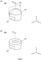
- Fig. 3 (a) is a perspective view showing the measurement object 200 as an example of the measurement object to be measured by the surface shape measurement apparatus 10 in the present embodiment
- Fig. 3 (b) is a perspective view of a measurement object 200' as an example of another measurement object.
- the surface shape measurement apparatus 10 in the present embodiment is an apparatus which strictly measures the surface shape of a substantially rotationally symmetric surface, and therefore at least part of the surface of a measurement object is a substantially rotationally symmetric surface.
- the measurement surface 201 of the measurement object 200 is a spherical surface protruding in the plus z-axis direction.
- the measurement surface 201 generally has, assuming that its rotational symmetry axis 210 is the z-axis and its radius is c, a shape obtained by a single rotation of (c 2 -x 2 ) 1/2 in the first quadrant of the x-z plane around the z-axis.
- the measurement surface has a shape obtained by a single rotation of the function represented in the first quadrant of the x-z plane around the z-axis, and may have a shape having a concaved top surface such as a measurement surface 201' of the measurement object 200'.
- the measurement objects 200 and 200' shown in the figure respectively include holding parts 202 and 202' so as to be easily fixed to the chuck 161
- the surface shape of a measurement object not including such a holding part can even be measured as long as it is fixed to the X-Y stage 160 via some tool, for example.
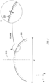
- Fig. 4 is a cross-sectional view and an enlarged view illustrating a surface shape to be measured.
- the cross-sectional view of Fig. 4 represents a section of the measurement object 200 taken in the plane A including the rotational symmetry axis 210 shown in Fig. 3 (a) .
- the measurement surface 201 is a rotationally symmetric surface as a whole, but has minute unevenness as seen in a locally enlarged view.
- the present embodiment assumes a measurement surface whose shape projected on the x-y plane has an outer perimeter of around ⁇ 100 mm (r in the figure). Then, the resolution for the depth direction of unevenness can be set to around 1 nm in accordance with the configuration and measurement principle of the measurement unit as described later.
- the term “resolution” refers to the finest unit at which the shape of a measurement target object can be identified as computed row data, and the "precision" at which the probability of measurement results is ensured is around 10 nm in the present embodiment.
- these orders may be changed depending on the configuration of the apparatus, the precision of sensors or the like.
- the depth direction of unevenness refers to the direction of the arrow shown in the enlarged view. More specifically, it refers to the direction orthogonal to the rotationally symmetric surface (indicated by the dotted line in the enlarged view).
- Fig. 5 is an illustration of the configuration and measurement principle of the measurement unit 110.
- Fig. 5 (a) is an illustration of the configuration and measurement principle of the distance measurement device 111
- Fig. 5 (b) is an illustration of the configuration and measurement principle of the angle measurement device 112.
- Each figure represents an example where a vertex of the measurement surface 201 is positioned at the origin of coordinates, and in which case the vertex is set as the measurement point.
- the distance measurement device 111 is configured of a first light source 1111 which generates first probe light, a condenser lens 1112 which condenses the first probe light generated by the first light source 1111 (first irradiation light PL1) to irradiate a measurement point on the measurement surface 201, a condenser lens 1113 which condenses the first probe light reflected at the measurement point (first reflected light RL1), a photodetector 1114 which detects the position of the first reflected light RL1, and the like.
- the angle measurement device 112 is configured of a second light source 1121 which generates second probe light, a condenser lens 1122 which condenses the second probe light generated by the second light source 1121 (second irradiation light PL2) to irradiate a measurement point on the measurement surface 201, a collimator lens 1123 which collimates the second probe light reflected at the measurement point (second reflected light RL2), a photodetector 1124 which detects the position of the second reflected light RL2, and the like.
- a second light source 1121 which generates second probe light
- a condenser lens 1122 which condenses the second probe light generated by the second light source 1121 (second irradiation light PL2) to irradiate a measurement point on the measurement surface 201
- a collimator lens 1123 which collimates the second probe light reflected at the measurement point (second reflected light RL2)
- a photodetector 1124 which detects the position of the second
- the first light source 1111 and the second light source 1121 are laser light sources with stabilized oscillation wavelength, optical output, beam pointing and the like, and a fiber laser, a DFB semiconductor laser or the like is used for them, for example.
- Output parts of the first light source 1111 and the second light source 1121 are provided with a collimator, and the first irradiation light PL1 and the second irradiation light PL2 converted into parallel light pencils are output from the respective light sources.
- the photodetectors 1114 and 1124 are detectors to detect the positions of the first reflected light RL1 and the second reflected light RL2, respectively, and a QPD (quadrant photodetector), an image capturing device such as CMOS or the like can be used for them, for example.
- QPD quadrant photodetector
- CMOS complementary metal-oxide-semiconductor
- the first irradiation light PL1 emitted from the first light source 1111 is condensed by the condenser lens 1112 and incident at the measurement point.
- the first reflected light RL1 reflected at the measurement point is condensed by the condenser lens 1113 and incident in the photodetector 1114.
- a distance d s from a reference position z 0 of the measurement unit 110 to the measurement point can be calculated based on a position detecting signal output from the photodetector 1114 to the measurement control part 186.
- the reference position z 0 may be, for example, the z coordinate of the rotation axis around which the first support 120 is rotated in the ⁇ x direction, or may be the z coordinate of a reference plane of the measurement unit 110 when it is opposed to the measurement surface 201.
- the second irradiation light PL2 emitted from the second light source 1121 is condensed by the condenser lens 1122 and incident at the measurement point.
- the second reflected light RL2 reflected at the measurement point is collimated by the collimator lens 1123 and incident in the photodetector 1124.
- the incident position of the second reflected light RL2 incident in the photodetector 1124 is varied.
- a reflection angle ⁇ s of the reflection surface at the measurement point can be calculated, and further an inclination angle that is the inclination of the reflection surface (described later) can be calculated.
- the distance measurement device 111 and the angle measurement device 112 are fixed to the holder 113, being adjusted such that a first reference plane formed by the first irradiation light PL1 and the first reflected light RL1 and a second reference plane formed by the second irradiation light PL2 and the second reflected light RL2 in the case where the inclination of the reflection surface at the measurement point is zero are orthogonal to each other.
- the first reference plane is in the x-z plane and the second reference plane is in the y-z plane.
- the distance measurement device 111 and the angle measurement device 112 are fixed to the holder 113, being adjusted such that the reflection points (measurement points) of the respective probe light overlap with each other at a reference distance d 0 from the reference position z 0 .
- the surface shape measurement apparatus 10 in accordance with the present embodiment has a precision of around 10 nm for the depth direction of unevenness. If it is attempted to obtain a precision of 10 nm only with the distance measurement device 111, it is thus required to prepare a distance measurement device having an output precision of 10 nm. Such a distance measurement device is not very practical due to being expensive and large in size.
- the distance measurement device 111 itself is a distance measurement device only having a capability of a lower precision than the target precision, and the angle measurement device 112 is provided in conjunction with the distance measurement device 111.
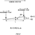
- ⁇ i 10 ⁇ rad. That is, if the angle measurement device 112 has a capability of 10 ⁇ rad as its output precision, measurement can be performed with a precision of 10 nm in the depth direction even if the sampling interval is around 1 mm.
- the distance measurement device 111 it is desirable to use the distance measurement device 111 in order that the measurement point as the target of the angle measurement device 112 and the reflection point of the second probe light coincide with each other. That is, if the scanning is performed such that the distance between the reference position z 0 of the measurement unit 110 and the measurement surface 201 is kept at the reference distance d 0 while monitoring the output of the distance measurement device 111, both measurement points of the distance measurement device 111 and the angle measurement device 112 coincide with each other, and therefore the measurement control part 186 can accurately grasp the measurement point being measured by the angle measurement device 112. If the distance measurement device 111 is not provided in conjunction, it is required to prepare another apparatus for accurately grasping the coordinates of the measurement point for the angle measurement device 112.
- an error range of the distance may be much wider than that of the depth-direction precision with which measurement is to be performed using the angle measurement device 112. That is, the output precision required for the distance measurement device 111 may be lower than the depth-direction precision with which measurement is to be performed. For example, it may be around 10 ⁇ m if the depth-direction precision with which measurement is to be performed is around 10 nm.
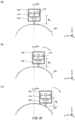
- Fig. 7 is an illustration of relative movement of the measurement object 200 and the head.
- a reference position 115 of the head is set on the rotation axis around which the first support 120 is rotated in the ⁇ x direction.
- Fig. 7 (a) shows an initial state in which the vertex of the rotationally symmetric surface can be measured.
- the measurement control part 186 acquires in advance first shape information as a piece of basic information of the measurement object 200.
- the first shape information is approximate shape data generated in the process of generating general shape data described later.
- the first shape information may be referred to as first shape data.
- the first shape data is a model defined in virtual space, and the position, attitude and shape thereof are defined in a set reference coordinate system.
- the first shape data is represented by a function.
- the measurement control part 186 uses the acquired first shape data to move the first support 120, the second support 130 and the X-Y stage 160 such that the reference position 115 is positioned above and at a distance of d 0 from the vertex of the rotationally symmetric surface that is the measurement surface 201. Then, the measurement control part 186 moves the measurement unit 110 to oppose the tangent plane of the vertex. In subsequent scanning processes as well, the measurement control part 186 controls the measurement unit 110 to oppose the tangent plane at the measurement point calculated from the acquired first shape data. That the measurement unit 110 opposes a tangent plane means that the tangent plane is also orthogonal to the first reference plane and the second reference plane as described above.
- Fig. 7 (b) shows the case where the measurement point is moved a little toward the periphery from the vertex of the measurement surface 201.
- the measurement control part 186 parallelly moves the second support 130 in the y direction and the z-axis direction, and also rotationally moves the first support 120 in the ⁇ x direction. More specifically, the movement is performed such that the distance from the reference position 115 is kept at d 0 while the tangent plane at the targeted measurement point and the measurement unit 110 oppose.
- the measurement control part 186 simultaneously rotationally moves the X-Y stage 160 in the ⁇ z direction.
- the measurement control part 186 does not parallelly move the X-Y stage 160 in x-y directions.
- the measurement control part 186 moves the X-Y stage 160 in parallel with the x-y plane when the measurement object 200 is to be moved to the position of the initial state after the user places the measurement object 200 on the X-Y stage 160, but does not perform the parallel movement during the measurement sequence for measuring the measurement surface 201. Accordingly, although the function to move the X-Y stage 160 in x-y directions is useful when the measurement object 200 is to be moved to the position of the initial state, the movement function can be omitted.
- the measurement control part 186 utilizes an output of the Z sensor 155 when the measurement unit 110 is to be moved to the position of the initial state. However, in scanning processes after the measurement unit 110 reaches the initial state, the measurement control part 186 can grasp the z direction position from the output of the distance measurement device 111, and therefore the output of the Z sensor 155 may not be monitored.
- Fig. 7 (c) shows the case where the measurement point is further moved toward the periphery.
- the measurement control part 186 further parallelly moves the second support 130 in the y direction and the z direction, and also further rotationally moves the first support 120 in the ⁇ x direction.
- the measurement control part 186 continues to rotationally move the X-Y stage 160 in the ⁇ z direction.
- Fig. 7 (a) to Fig. 7 (c) scanning of the head relative to the measurement surface 201 is performed only in a direction along the y-axis, and does not involve parallel movement in the x direction. Also, scanning in the y direction is performed only in the negative y region in the figure, and scanning is not performed in the positive region. That is, by rotationally moving the X-Y stage 160 in the ⁇ z direction, the entire measurement surface can be measured by such a simple movement control.
- the degree of freedom that the head is to have and the degree of freedom that the stage on which the measurement object is placed is to have are optimized for the dedicated purpose of measuring the surface shape of a rotationally symmetric surface.
- the drive configuration of the head and the drive configuration of the stage can each be simplified. In particular, simplification of the drive configuration of the head contributes to weight reduction of the head and also contributes to speed enhancement of movement of the head.
- Fig. 8 is an illustration of a measurement path of the measurement surface 201.
- Fig. 8 (a) shows a measurement path formed by the controls described using Fig. 7 as observed in the z direction.
- the measurement path is a locus obtained by connecting adjacent measurement points.
- a start point is the vertex of the rotationally symmetric surface, and corresponds to the initial state as shown in Fig. 7 (a) .
- the measurement path forms a spiral.
- the measurement control part 186 receives outputs from the angle measurement device 112 in the order along the path.
- the measurement results at the cross-marked points where the line C and the spiral path intersect are extracted and rearranged.
- the measurement results of the square-marked points where the line C and the spiral path intersect are extracted and rearranged. If an intersection point is not a measurement point, it is required to perform interpolation from the measurement results of neighboring measurement points for the calculation.
- the inclination angle at the measurement point calculated from the output of the angle measurement device 112 is calculated as an angle formed by the tangent plane at a measurement point calculated from the first shape data and an actual tangent plane at the measurement point. Accordingly, if the depth in a direction along a certain path is to be calculated, the computations described using Fig. 6 are performed after converting it into angle along the direction. Note that computations from when the output of the angle measurement device 112 is obtained until when surface shape data that is second shape information having a higher precision than the first shape data is calculated are performed by the computation part 187 that functions as a second calculation part. In subsequent descriptions, the second shape information may be referred to as second shape data.
- Fig. 8 (b) shows a measurement path of another example as observed in the z direction. If information of the cross-sectional shape taken in a particular section is to be obtained without performing the above-described interpolation, the measurement path may be set to form a radial locus centered at the vertex as shown in the figure. If a plurality of pieces of cross-sectional shape information is to be obtained, setting the start point near the end portion of the measurement surface 201 rather than at the vertex allows the measurement path to be set in a unicursal manner. If such a measurement path is to be set, the measurement control part 186 performs scanning by moving the head also in the positive y region described in Fig. 7 .
- the measurement control part 186 performs rotational movement of the X-Y stage 160 in the ⁇ z direction only when movement is performed along the arc paths in the figure. Then, the measurement control part 186 does not perform movement of the first support 120 and the second support 130.
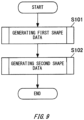
- Fig. 9 is a flow chart illustrating the operation of the surface shape measurement apparatus in the present embodiment.
- the operation of the surface shape measurement apparatus 10 is broadly divided into generation of the first shape data (step S101) and generation of the second shape data (step S 102).
- step S101 the surface shape measurement apparatus 10 generates the first shape data from three-dimensional coordinate data of the measurement surface 201 acquired by the distance measurement device 111.
- step S102 the surface shape measurement apparatus 10 generates the second shape data from four-dimensional data including a coordinate value and a surface inclination value acquired by the distance measurement device 111 and the angle measurement device 112 using the generated first shape data.
- Fig. 10 is an illustration of an operation of acquiring the first shape data that is three-dimensional coordinate data of a measurement object whose shape data is unknown.
- the fact that the surface shape of the unknown measurement object is substantially rotationally symmetric is regarded to be known. Note that the contents described using Fig. 7 are omitted.
- Fig. 10 (a) an initial state in which the vertex of the rotationally symmetric surface or a point near the vertex can be measured.
- the distance measurement device 111 is used among the two measurement devices.
- a user arranges the measurement object on the X-Y stage such that the vertex of a rotationally symmetric surface that is the measurement surface 201 and the rotation axis of the X-Y stage 160 approximately coincide with each other. Then, the first support 120, the second support 130 and the X-Y stage 160 are moved such that the reference position 115 is positioned above and at a distance of d 0 from the vertex of the rotationally symmetric surface that is the measurement surface 201. Then, the measurement control part 186 sets the attitude of the measurement unit 110 to be horizontal. In subsequent scanning processes as well, the measurement control part 186 keeps the attitude of the measurement unit 110 to be horizontal, and does not rotationally drive the first support 120 relative to the second support 130.
- driving is performed such that the line of intersection of the first reference plane, which is a plane formed by the optical axis of the condenser lens 1112 and the optical axis of the condenser lens 1113, and the second reference plane, which is a plane formed by the optical axis of the condenser lens 1122 and the optical axis of the collimator lens 1123, is substantially parallel to the z-axis in the sequence of acquiring the three-dimensional coordinate data.
- Fig. 10 (b) shows the case where the measurement point is moved a little toward the periphery from the vertex of the measurement surface 201.
- the measurement control part 186 parallelly moves the second support 130 in the y direction and the z direction. More specifically, the second support 130 is moved such that the distance from the reference position 115 is kept at d 0 .
- the measurement control part 186 simultaneously rotationally moves the X-Y stage 160 in the ⁇ z direction. Then, the measurement control part 186 does not parallelly move the X-Y stage 160 in x-y directions.
- Fig. 10 (c) shows the case where the measurement point is further moved toward the periphery.
- the measurement control part 186 further parallelly moves the second support 130 in the y direction and the z direction.
- the measurement control part 186 continues to rotationally move the X-Y stage 160 in the ⁇ z direction.
- Three-dimensional coordinate data of the measurement surface 201 is obtained from the y-z coordinates of the reference position 115 of the head, the rotation angle ⁇ z of the X-Y stage 160 and the reference distance d 0 . Note that, as described with reference to Fig. 8 , measurement points are arranged on a radial line passing through a spiral path and through the rotation center on the measurement surface 201.
- Fig. 11 is a flow chart representing a procedure of generating the first shape data and shows a specific flow of step S101 in Fig. 9 . Note that, in the flow, step S1011 starts at the time after the measurement object 200 is arranged on the X-Y stage 160 by the user and when an instruction of generating the first shape data is received from the user via the user interface 182.
- the measurement control part 186 drives the X-Y stage 160, the first support 120 and the second support 130 to move the measurement object 200 to an initial position. Then, while driving the X-Y stage 160 and the second support 130 to cause the measurement unit 110 scan the measurement surface 201 as described using Fig. 10 , three-dimensional coordinate values of the measurement surface 201 detected by the distance measurement device 111 are acquired to sequentially accumulate them in the memory 183. When the end point of the measurement points is reached, the flow advances to step S1012.
- the image generation part 188 generates three-dimensional plot image data representing a spatial distribution of the three-dimensional coordinate data accumulated in the memory 183, and displays it as a three-dimensional plot image on the user interface 182 (step S1012).
- the user can visually grasp a general shape of the unknown measurement surface 201, and can use it as a guide for selecting the fitting parameters described later.
- the computation part 187 performs fitting by function in order to generate a function representing an approximate curved surface of the acquired three-dimensional coordinate data as the first shape data (step S1013).
- the function may be referred to as a fitting function.
- the computation part 187 functions as a first calculation part which calculates the first shape data from the acquired three-dimensional coordinate data of the measurement surface 201.
- the fitting function is, for example, a Zernike polynomial. Note that, while a plurality of notational systems such as Standard Zernike and FRINGE Zernike, which are different in the order of terms from each other, can be used for for Zernike polynomials, the following descriptions describes the case of FRINGE Zernike.
- the computation part 187 stores Zernike coefficients selected and specified by the user via the user interface 182 and used for fitting, as parameter information in the memory 183.
- the Zernike coefficients of terms of the Zernike polynomial representing a rotationally symmetric shape such as the fourth term, the ninth term and the sixteenth term, are selected as parameters.
- the parameters may be referred to as fitting parameters.
- the fitting is performed by numerical optimization which derives the optimal combination of parameters by repeatedly varying the fitting parameters (Zernike coefficients) such that the sum of the squares of deviations of the three-dimensional coordinate data from the fitting function (Zernike polynomial) is minimized.
- the damped least squares method can be used as the optimization method, for example, but the method is not so limited and may adopt a known optimization method.
- the computation part 187 calculates a fitting residual.
- the fitting residual indicates the gap between the fitting function and the three-dimensional coordinate data, and is an RMS (root mean square) value, for example.
- the fitting residual may be referred to as an RMS residual.
- the computation part 187 stores the calculated RMS residual in the memory 183.
- the image generation part 188 generates three-dimensional plot image data of the found fitting function and the three-dimensional coordinate data, and displays it as a three-dimensional plot image together with the RMS residual value on the user interface 182 (step S1014). In this manner, the user can check the precision of the fitting. Also, the user can check a region in which the fitting is not satisfactorily performed, and it becomes easy to specify a parameter lacking as a degree of freedom (a Zernike term required for the fitting).
- the system control part 181 receives an instruction of whether or not to reperform the fitting process from the user (step S1015). For example, a display window for making the user select whether to end the fitting process or to reperform the fitting process with fitting parameters added or changed is displayed on the user interface 182.
- step S1015 If the specification of the fitting parameters is changed and it is determined that an instruction to reperform the fitting process is given the user (YES at step S1015), the system control part 181 advances to step S1013 and performs the subsequent flow.
- the system control part 181 determines the acquired fitting function as the first shape data, and stores it in the memory 183. Then, a sequence of processes of generating the first shape data ends.
- Fig. 12 is an illustration of the placement error of the measurement object 200.
- the measurement object 200 indicated by the solid line is correctly placed at the target position on the X-Y stage 160.
- the rotational symmetry axis 210 of the measurement surface 201 coincides with the axis of rotation of the X-Y stage 160 in the ⁇ z direction.
- a measurement object 200" indicated by the dotted line is placed with a deviation relative to the X-Y stage 160.
- the vertex of a measurement surface 201" of the measurement object 200" is deviated by ⁇ x in the x direction and ⁇ y in the y direction relative to the vertex of the measurement surface 201 of the measurement object 200.
- the chuck 161 to fix the measurement object 200 is omitted in the figure.
- the deviation may occur not only in the x direction and the y direction but also in the z direction, the ⁇ x direction, the ⁇ y direction and the ⁇ z direction. It may be due to deviation between the chuck 161 and the X-Y stage 160, deviation between the chuck 161 and the holding part 202 of the measurement object 200 and the like. However, some deviation components can be substantially ignored by precisely configuring the chuck 161 and the X-Y stage 160 with each other or adopting a precisely plane surface as the bottom surface of the measurement object 200. If some deviation components can be substantially ignored, the load of the fitting computation described later is mitigated.
- the surface shape measurement apparatus 10 presents the amount of unevenness relative to a first shape data as a measurement result of the surface shape.
- the first shape data is acquired in advance through the process of generating general shape data described with reference to Fig. 10 and Fig. 11 .
- the placement error relative to the target position is calculated by comparing the surface information of the first shape data in the case of placement at the target position and the measurement result that is actually measured.
- Fig. 13 is a schematic illustration of calculation of the placement error.
- a temporary surface shape of the measurement surface 201" placed with a deviation relative to the target position is calculated from the output of the measurement unit 110.
- scanning of the measurement unit 110 is performed based on the first shape data in the case of placement at the target position, and therefore a measurement point recognized by the measurement control part 186 is deviated from an actual measurement point, and the precision of the surface shape that is first calculated is not high.
- unevenness in the surface is minute, and therefore it can be regarded that the entire shape of the surface to be calculated is very close to the surface shape of the first shape data.
- the placement error is calculated by fitting the surface shape of the first shape data with this actually measured surface shape.
- the fitting computation for calculating the placement error is an operation of calculating the amounts of movement of the first shape data when it is moved in the directions of six degrees of freedom by a minute amount for each direction such that the degree of coincidence with the actually measured surface shape data is maximum. More specifically, the combination of the amounts of movement of the first shape data when it is parallelly moved ( ⁇ x, ⁇ y, ⁇ z) and rotationally moved ( ⁇ x, ⁇ y, ⁇ z) such that the deviation from the actually measured surface shape data is minimized is derived by numerical optimization. That is, the placement error is determined by the movement amounts ( ⁇ x, ⁇ y, ⁇ z, ⁇ x, ⁇ y, ⁇ z).
- the fitting computation is performed by comparing the surface shape of the first shape data and the actually measured surface shape in the present embodiment
- the fitting computation may be performed in the dimension of angle for both. That is, by differentiating the function of the first shape data to the first order to represent it as an angle distribution, it can be directly compared with an actually measured angle distribution as an output of the measurement unit 110.
- the fitting computation using the angle distribution can precisely calculate the placement error because an integration process is not involved.
- FIG. 14 is an illustration of the relationship between a position near the measurement point and the second probe light of the angle measurement device 112.
- the figure represents a simplified view of the angle measurement device 112 with the second light source 1121 and the photodetector 1124.
- the ideal measurement surface of the first shape data is represented as a reference measurement surface Hd
- the actual measurement surface is represented as an actually measured measurement surface Hr.
- the measurement surface has a three-dimensional shape, and therefore each phenomenon is observed as a three-dimensional phenomenon such as that reflected light of the second probe light has a three-dimensional vector component, in practice, while the present example is described focusing on phenomena in y-z directions for simplification of descriptions.
- Fig. 14 (a) shows the case where the reference measurement surface Hd is arranged at the target position and the reference position 115 of the measurement unit 110 strictly opposes the reference measurement surface Hd.
- the measurement unit 110 is rotated by ⁇ R in the ⁇ x direction, and there is no rotation error of the second support 130.
- the second probe light emitted from the second light source 1121 if it is reflected at a measurement point Ri on the reference measurement surface Hd, is incident at an incident point Pi that is the center of the photodetector 1124. That is, the inclination of the surface at the measurement point Ri is detected as zero.
- Fig. 14 (b) shows the case where the reference measurement surface Hd is arranged at the target position and the measurement unit 110 opposes the reference measurement surface Hd with the rotation error ⁇ .
- the minute rotation angle ⁇ of the second support 130 can be accurately measured by the interferometer unit 151, and therefore the measurement control part 186 accurately grasps an emission position and an emission direction of the second probe light emitted from the second light source 1121.
- the computation part 187 receives information of the emission position and the emission direction of the second probe light, and estimates the output of the photodetector 1124 by ray tracing. Specifically, the computation part 187 calculates the coordinates of the measurement point Rs on the reference measurement surface Hd by ray tracing, calculates the normal direction of the reference measurement surface Hd at the measurement point Rs, and obtains a reflection direction of the second probe light using the normal direction.
- an incident point Ps of the photodetector 1124 is calculated by further performing ray tracing. That is, the estimated output value of the incident point Ps obtained in this process is a value calculated in consideration of the minute rotation angle ⁇ of the second support 130 as an error factor.
- Fig. 14 (c) shows the case where the actually measured measurement surface Hr is arranged at the target position and the measurement unit 110 opposes the reference measurement surface Hd with the rotation error ⁇ . That is, the relative relationship between the angle measurement device 112 and each of the actually measured measurement surface Hr and the reference measurement surface Hd is similar to the case of Fig. 14 (b).
- Fig. 14 (c) shows the second probe light in the case of obtaining an actual output value rather than the estimated output value obtained by ray tracing as in Fig. 14 (b) .
- the second probe light emitted from the second light source 1121 is incident at the measurement point Rh on the actually measured measurement surface Hr, is reflected according to the inclination of the actually measured measurement surface Hr at the measurement point Rh, and reaches the photodetector 1124.
- An incident point Ph of the photodetector 1124 is at the coordinates corresponding to the inclination of the actually measured measurement surface Hr, and the photodetector 1124 outputs a detection signal corresponding to the incident point Ph as the actual output value.
- the actual output value is a value output with the minute rotation angle ⁇ of the second support 130 as an error factor.
- the inclination (referred to as ⁇ d ) of the reference measurement surface Hd at the measurement point Rs is obtained from the ray tracing computation in Fig. 14 (b)
- the inclination (referred to as ⁇ r ) of the actually measured measurement surface Hr at the measurement point Rh is obtained from the actual output value in Fig. 14 (c) .
- ⁇ d The inclination of the reference measurement surface Hd at the measurement point Rs is obtained from the ray tracing computation in Fig. 14 (b)
- the inclination (referred to as ⁇ r ) of the actually measured measurement surface Hr at the measurement point Rh is obtained from the actual output value in Fig. 14 (c) .
- the actual inclination relative to the reference measurement surface at the coordinates Rs can be evaluated as ⁇ r - ⁇ d .
- the inclination ⁇ i in Fig. 6 is equal to ⁇ r - ⁇ d . That is, the computation in Fig. 6 can be performed by calculating ⁇ r - ⁇ d .
- Fig. 14 (d) shows the case where the actually measured measurement surface Hr is arranged at a position deviated by the placement error ⁇ y, and the reference measurement surface Hd is arranged at the target position and the measurement unit 110 opposes the reference measurement surface Hd with the rotation error ⁇ .
- Fig. 14 (d) shows the second probe light in the case of obtaining an actual output value rather than the estimated output value obtained by ray tracing as in Fig. 14 (b) .
- the second probe light emitted from the second light source 1121 is incident at a measurement point Rr on the actually measured measurement surface Hr, is reflected according to the inclination of the actually measured measurement surface Hr at the measurement point Rr, and reaches the photodetector 1124.
- An incident point Pr of the photodetector 1124 is at the coordinates corresponding to the inclination of the actually measured measurement surface Hr, and the photodetector 1124 outputs a detection signal corresponding to the incident point Pr as the actual output value.
- the actual output value is a value output with the minute rotation angle ⁇ of the second support 130 and the placement error ⁇ y as error factors.
- the measurement control part 186 does not grasp the placement error, and therefore the obtained actual output value is recognized as an actual output value for the coordinates Rs of the reference measurement surface Hd calculated by ray tracing in Fig. 14 (b) without consideration of the placement error.
- the computation part 187 recognizes the measurement result of the measurement point Rr as the measurement result of the coordinates Rs. That is, it can be regarded that such inconsistency in correspondence is included in the actual output value with the placement error ⁇ y as an error factor.
- the difference between the actual inclination at the measurement point Rr and the inclination of the reference measurement surface Hd at the coordinates Rs is recognized as the inclination ⁇ i at the coordinates Rs.
- the surface shape obtained by performing the computation described using Fig. 6 on the calculated value including the placement error as an error factor in this manner is the actually measured surface shape described using Fig. 13 . That is, the actually measured surface shape that is first derived with the placement error as an error factor may have a low precision. However, as described above, the actually measured surface shape as a whole can be regarded to be very close to the surface shape of the first shape data, and therefore a placement error amount is calculated by a fitting computation.
- the reference measurement surface Hd is rearranged at a position deviated from the target position by the placement error amount and the ray tracing computation in Fig. 14 (b) is performed again.
- the coordinates of a new measurement point Rs on the reference measurement surface Hd obtained by the recomputation substantially coincide with the coordinates of the measurement point Rr in Fig. 14 (d) . Accordingly, the placement error ⁇ y is almost eliminated, and ⁇ d and ⁇ r at substantially the same point are obtained, and therefore the accurate inclination ⁇ i can be calculated.
- a more precise surface shape can be derived by performing the computation described using Fig. 6 again using ⁇ i calculated in this manner.
- the above-described computation may be repeatedly performed by subjecting again a recomputed surface shape to the fitting computation for calculating the placement error amount to further calculate a placement error until the degree of coincidence as an evaluation value exceeds a predetermined threshold.
- the surface shape derived at the time when the degree of coincidence exceeds the threshold is determined as the final surface shape.
- Fig. 15 is a flow chart representing a procedure to obtain second shape data. As described using Fig. 9 , the flow starts at the time when, after the first shape data is generated and stored in the memory 183, the measurement object 200 is placed on the X-Y stage 160 by a user and receives an instruction to start measurement from the user via the user interface 182.
- the measurement control part 186 drives the X-Y stage 160, the first support 120 and the second support 130 to move the measurement object 200 to an initial position. Then, outputs of measurement points are obtained by the measurement unit 110 to sequentially accumulate information of the measurement points, while driving the X-Y stage 160, the first support 120 and the second support 130 such that the measurement unit 110 scans the measurement surface 201, as described using Fig. 7 and Fig. 8 . When the end point of the measurement points is reached, the flow advances to step S2012.
- the computation part 187 assumes that the measurement object 200 is placed at the target position on the X-Y stage 160, and sets the placement position of the reference measurement surface of the first shape data as the initial position with zero error amount.
- the flow proceeds to step S2013, and then the computation part 187 performs the ray tracing computation in Fig. 14 (b) and uses the result of the ray tracing computation to perform the computation for acquiring the actually measured surface shape in Fig. 14 (d) .
- step S2014 the computation part 187 performs the computation of fitting the reference measurement surface and the actually measured surface shape as described using Fig. 13 .
- the placement error amount of the measurement object 200 relative to the X-Y stage 160 is calculated by the fitting computation.
- the computation part 187 determines whether an evaluation criterion is satisfied or not.
- the evaluation criterion may be whether the calculated placement error amount does not exceed a predetermined reference error amount, or may be whether the maximum degree of coincidence between the reference measurement surface and the actually measured surface shape calculated by the fitting computation exceeds a predetermined threshold.
- its reference value may be changed according to a desired measurement precision, the shape of the measurement object 200 or the like, another criterion may be adopted, or a plurality of criteria may be used in combination.
- step S2012 the computation part 187 deviates the placement position of the reference measurement surface by the placement error amount calculated by the fitting computation at step S2014. In this manner, it can be expected that the reference measurement surface becomes closer to the actually measured measurement surface 201 than at the time of the previous computation. Then, the steps after step S2013 are performed again using a new reference measurement surface.
- step S2015 When it is determined that the evaluation criterion is satisfied at step S2015, the flow proceeds to step S2016, and then the computation part 187 determines the actually measured surface shape derived as the final measurement result.
- the actually measured surface shape determined may be converted as a graphic image by the image generation part 188 to display it on the user interface 182.
- a sequence of processes ends when presentation to the user ends.
- the fitting computations may be performed by external computation equipment.
- the surface shape measurement apparatus 10 may be configured to have a communication part so as to be connected to an external cloud server, and to perform the fitting process computations on the cloud server.
- the ray tracing computation of step S2013 in Fig. 15 may be performed by external computation equipment similarly.
- an eccentric parameter as a movement amount for coincidence of the positions and attitudes may be selected in conjunction to simultaneously perform elimination of the placement error.
- the problem that the fitting does not converge due to the placement error can be avoided by adding the eccentric parameter as a fitting parameter.
- the fitting computation for eliminating the placement error described using Fig. 13 can be skipped.
- the first shape data of an unknown measurement object is determined as the fitting function that is an approximate curved surface of the three-dimensional coordinate data acquired using the distance measurement device in the above embodiment
- the first shape data may be configured by a subroutine for interpolating the shape of the acquired three-dimensional coordinate data without performing fitting with function.
- a NURBS National Uniform Rational B-Spline
- the first shape data of the measurement object can be generated regardless of the distribution shape of the three-dimensional coordinate data and the placement error of the measurement object.
- the fitting function may be arbitrarily defined by the user.
- the fitting function may also be arbitrarily selected by the user from a plurality of functions in the fitting process for the first shape data.
- a function representing a spherical surface can be used as the fitting function (the fitting parameter is only the curvature or the radius of curvature).
- the amounts of parallel movement until the centers of curvature coincide ( ⁇ x, ⁇ y, ⁇ z) can be calculated while the amounts of rotational movement ( ⁇ x, ⁇ y, ⁇ z) can not be uniquely defined.
- the subsequent fitting computation processes are performed with predetermined values set as the amounts of rotational movement, for example. It is because, in the case of a spherical surface, the coordinates of the measurement point can be correctly calculated in the ray tracing computation as long as the amounts of parallel movement ( ⁇ x, ⁇ y, ⁇ z) are grasped.
- the surface shape measurement apparatus 10 described above moves the head provided with the measurement unit 110 in three degrees of freedom consisting of parallel movement in y-z plane and rotational movement in the ⁇ x direction. Weight reduction of the head is achieved and speed enhancement of measurement is realized by adopting the configuration in which the head can move only in the three degrees of freedom. However, the speed enhancement of measurement is significantly contributed to not only by optimization of the head configuration but also simplification of controls and simplification of computations by limiting the degree of freedom of movement to the three degrees of freedom.
- the speed enhancement of measurement can be realized by performing controls limited to three degrees of freedom consisting of parallel movement in the y-z plane and rotational movement in the ⁇ x direction in the case of measuring a rotationally symmetric surface. That is, accurate and rapid measurement can be realized by the measurement control part performing controls while limiting movement of the head to the three degrees of freedom. Accordingly, even if the measurement apparatus is a general-purpose apparatus, the speed enhancement of measurement can be expected to be realized at a certain level by changing the measurement control program in the case of measuring a rotationally symmetric surface.
- the measurement surface 201 is a rotationally symmetric surface
- a precise surface shape can be derived by a similar method.
- configurations that are based on the characteristics of a rotationally symmetric surface may be changed among the configurations described above.
- the surface shape measurement apparatus 10 adopts a mechanism to move the first support 120 in the x direction and also rotates it in the ⁇ y direction so that the measurement unit 110 can take an attitude opposing the measurement point.
- a sensor is also provided to monitor the movement amount and the rotation angle.
- the initial position is adopted such that the rotational symmetry axis of the rotationally symmetric surface and the rotation axis of ⁇ z rotation approximately coincide with each other.
- the initial position relative to the X-Y stage 160 is different from it.
- a measurement point on a free-form surface is set differently from the case of utilizing symmetry of the rotationally symmetric surface as described using Fig. 8 and, for example, the measurement point is set at a lattice point of its projection on the x-y plane.
- the measurement control part 186 does not rotate the X-Y stage 160 in the ⁇ z direction but parallelly move it in x-y directions during measurement.
- the initial position may be defined at any position.
- movement of the X-Y stage 160 in x-y directions has a precision similar to the precision of movement of the second support 130 in y-z directions.
- a component of rotation of the X-Y stage 160 in the ⁇ z direction is also precisely detected utilizing a similar interferometer unit, for example.
- step S2012 to step S2015 described above If the deviation between the rotational symmetry axis of the rotationally symmetric surface and the rotation axis of ⁇ z rotation does not cause the difference between the actual reflection point and the coordinates of the measurement point being recognized as described using Fig. 14 (d) , the processes from step S2012 to step S2015 described above is unnecessary. In other words, the difference between the actual reflection point and the coordinates of the measurement point being recognized can be practically ignored by performing the measurement of step S 2011 while controlling the measurement unit 110 to take an attitude opposing the measurement point using the fitting function calculated as the first shape data.
- the depth direction of unevenness is described as a direction orthogonal to the rotationally symmetric surface in Fig. 4
- the depth of unevenness to be derived as the surface shape may simply be the depth in the z direction, for example.
- the measurement control part 186 performs measurement such that the measurement unit 110 takes an attitude opposing the measurement point, and therefore information of unevenness to be measured has a three-dimensional vector. Accordingly, depending on which section the user needs to evaluate the surface shape in, the surface shape in the section can be generated by resolving the unevenness information into components for the directions of the section.
- a Zernike polynomial that is easily applied to a rotationally symmetric surface is used as the fitting function in the above-described embodiment
- a variety of fitting functions can be applied to a free-form surface.
- an X-Y polynomial can be used.
- 10 surface shape measurement apparatus, 100: base, 101: ⁇ z driving motor, 102: X-Y driving motor, 103: ⁇ z sensor, 104: X-Y sensor, 110: measurement unit, 111: distance measurement device, 112: angle measurement device, 113: holder, 115: reference position, 120: first support, 130: second support, 131: rotary encoder, 132: ⁇ x driving motor, 140: first frame, 141: Y-Z driving motor, 150: second frame, 151: interferometer unit, 153: first interferometer, 154: second interferometer, 155: Z sensor, 160: X-Y stage, 161: chuck, 180: control unit, 181: system control part, 182: user interface, 183: memory, 186: measurement control part, 187: computation part, 188: image generation part, 200: measurement object, 201: measurement surface, 202: holding part, 210: rotational symmetry axis, 1111: first light source, 1112, 1113, 1122:
Landscapes
- Physics & Mathematics (AREA)
- General Physics & Mathematics (AREA)
- Length Measuring Devices By Optical Means (AREA)
- Length Measuring Devices With Unspecified Measuring Means (AREA)
Claims (13)
- Appareil de mesure de forme de surface (10) pour mesurer une forme de surface d'un objet de mesure, dans lequel l'appareil de mesure de forme de surface comprend :une unité de mesure (110) comprenant un dispositif de mesure de distance (111) agencé pour mesurer une distance jusqu'à un point de mesure sur une surface de l'objet de mesure en utilisant une première lumière de sonde et un dispositif de mesure d'angle (112) agencé pour mesurer une inclinaison de la surface au niveau dudit point de mesure en utilisant une seconde lumière de sonde ;une première partie de calcul (187) configurée pour calculer des données de forme de référence de l'objet de mesure sur la base de la distance mesurée par le dispositif de mesure de distance ; etune seconde partie de calcul (187) configurée pour calculer des données de forme détaillées de l'objet de mesure sur la base de ladite inclinaison au niveau du point de mesure mesurée par le dispositif de mesure d'angle, desdites données de forme de référence calculées, et d'un intervalle d'échantillonnage qui est l'intervalle d'échantillonnage lors du balayage du dispositif de mesure d'angle,dans lequel la première lumière de sonde et la seconde lumière de sonde se chevauchent à une distance de référence à partir d'une position de référence de l'appareil de mesure de forme de surface, etdans lequel l'appareil de mesure de forme de surface est configuré pour effectuer un balayage de telle sorte que la distance entre l'unité de mesure et la surface de l'objet de mesure est maintenue à la distance de référence.
- Appareil de mesure de forme de surface selon la revendication 1, dans lequel les données de forme détaillées sont plus précises que les données de forme de référence.
- Appareil de mesure de forme de surface selon la revendication 1 ou 2, comprenant :un support (120) agencé pour supporter le dispositif de mesure de distance et le dispositif de mesure d'angle ;une partie d'entraînement (132, 141) agencée pour déplacer le support par rapport à l'objet de mesure ; etune partie de commande (186) configurée pour commander la partie d'entraînement, dans lequellors de la mesure de l'inclinaison par le dispositif de mesure d'angle, la partie de commande est configurée pour amener le support à effectuer un balayage par la partie d'entraînement de telle sorte que le support s'oppose à un plan tangent au point de mesure calculé à partir des données de forme de référence et qu'une distance à partir du point de mesure est constante.
- Appareil de mesure de forme de surface selon la revendication 3, dans lequell'objet de mesure présente au moins partiellement une forme sensiblement à symétrie de rotation, et une cible de mesure est une forme de surface d'une surface à symétrie de rotation,l'appareil de mesure de forme de surface comprend :une platine (160) agencée pour supporter l'objet de mesure ; etune partie d'actionnement (101, 102) agencée pour déplacer en rotation la platine autour d'un axe parallèle à un axe de symétrie de rotation de la surface à symétrie de rotation, etlors de la mesure de la distance par le dispositif de mesure de distance et de la mesure de l'inclinaison par le dispositif de mesure d'angle, la partie de commande (186) est configurée pour amener la platine à être déplacée en rotation par la partie d'actionnement.
- Appareil de mesure de forme de surface selon la revendication 4, dans lequel
la seconde partie de calcul est configurée pour calculer une quantité d'erreur d'une erreur de placement de l'objet de mesure par rapport à la platine en raison d'une déviation entre l'axe de symétrie de rotation de l'objet de mesure et un axe de rotation de mouvement de rotation de la platine, et pour calculer les données de forme détaillées en utilisant les données de forme de référence modifiées en tenant compte de la quantité d'erreur et d'une sortie du dispositif de mesure d'angle. - Appareil de mesure de forme de surface selon la revendication 5, dans lequel la seconde partie de calcul est configurée pour recalculer la quantité d'erreur en utilisant les données de forme détaillées obtenues temporairement, et recalcule en outre les données de forme détaillées sur la base de la quantité d'erreur recalculée.
- Appareil de mesure de forme de surface selon l'une quelconque des revendications 1 à 6, dans lequelle dispositif de mesure de distance inclut une première source de lumière (1111) et un premier photodétecteur (1114) agencé pour détecter une première lumière réfléchie qui a été réfléchie sur l'objet de mesure de la lumière générée par la première source de lumière, etle dispositif de mesure d'angle inclut une seconde source de lumière (1121) et un second photodétecteur (1124) agencé pour détecter une seconde lumière réfléchie qui a été réfléchie sur l'objet de mesure de la lumière générée par la seconde source de lumière.
- Appareil de mesure de forme de surface selon la revendication 7, dans lequel
un premier plan de référence entre la première source de lumière et le premier photodétecteur et un second plan de référence entre la seconde source de lumière et le second photodétecteur sont fournis de sorte que le premier plan de référence et le second plan de référence sont orthogonaux l'un à l'autre. - Appareil de mesure de forme de surface selon l'une quelconque des revendications 1 à 8, dans lequelle dispositif de mesure de distance inclut une lentille de condenseur (1113) agencée pour condenser la première lumière réfléchie, etle dispositif de mesure d'angle inclut une lentille de collimateur (1123) agencée pour collimater la seconde lumière réfléchie.
- Procédé de mesure de forme de surface pour mesurer une forme de surface d'un objet de mesure comprenant :une étape de mesure de distance pour mesurer une distance jusqu'à un point de mesure sur une surface de l'objet de mesure par un dispositif de mesure de distance (111) en utilisant une première lumière de sonde ;une première étape de calcul pour calculer des données de forme de référence de l'objet de mesure sur la base de la distance mesurée dans l'étape de mesure de distance ;une étape de mesure d'angle pour mesurer une inclinaison de la surface au niveau du point de mesure par un dispositif de mesure d'angle (112) en utilisant une seconde lumière de sonde ; etune seconde étape de calcul pour calculer des données de forme détaillées de l'objet de mesure sur la base de ladite inclinaison au niveau du point de mesure mesurée dans l'étape de mesure d'angle, les données de forme de référence, et un intervalle d'échantillonnage lors du balayage du dispositif de mesure d'angle,dans lequel la première lumière de sonde et la seconde lumière de sonde se chevauchent à une distance de référence à partir d'une position de référence de l'appareil de mesure de forme de surface, etdans lequel le balayage est effectué de telle sorte que la distance entre i) une unité de mesure (110) comprenant le dispositif de mesure de distance et le dispositif de mesure d'angle et ii) la surface de l'objet de mesure est maintenue à la distance de référence.
- Procédé de mesure de forme de surface selon la revendication 10, dans lequel
dans l'étape de mesure d'angle, un support (120) qui supporte le dispositif de mesure de distance et le dispositif de mesure d'angle est amené à effectuer un balayage de telle sorte que le support s'oppose à un plan tangent au point de mesure calculé à partir des données de forme de référence et qu'une distance à partir du point de mesure est constante. - Programme de mesure de forme de surface pour mesurer une forme de surface d'un objet de mesure, dans lequel le programme de mesure de forme de surface peut être exécuté pour amener un appareil de mesure de forme de surface selon les revendications 1 à 9 à mettre en oeuvre le procédé selon la revendication 10 ou 11.
- Support d'enregistrement lisible par ordinateur stockant le programme selon la revendication 12.
Applications Claiming Priority (2)
| Application Number | Priority Date | Filing Date | Title |
|---|---|---|---|
| JP2015171423 | 2015-08-31 | ||
| PCT/JP2016/075506 WO2017038875A1 (fr) | 2015-08-31 | 2016-08-31 | Dispositif de mesure de forme de surface et programme de mesure de forme de surface |
Publications (3)
| Publication Number | Publication Date |
|---|---|
| EP3346231A4 EP3346231A4 (fr) | 2018-07-11 |
| EP3346231A1 EP3346231A1 (fr) | 2018-07-11 |
| EP3346231B1 true EP3346231B1 (fr) | 2023-08-09 |
Family
ID=58188884
Family Applications (1)
| Application Number | Title | Priority Date | Filing Date |
|---|---|---|---|
| EP16841905.9A Active EP3346231B1 (fr) | 2015-08-31 | 2016-08-31 | Dispositif de mesure de forme de surface, méthode et programme de mesure de forme de surface |
Country Status (3)
| Country | Link |
|---|---|
| EP (1) | EP3346231B1 (fr) |
| JP (1) | JP6489220B2 (fr) |
| WO (1) | WO2017038875A1 (fr) |
Families Citing this family (3)
| Publication number | Priority date | Publication date | Assignee | Title |
|---|---|---|---|---|
| RU183443U1 (ru) * | 2017-10-03 | 2018-09-24 | Ростовский вертолётный производственный комплекс, Публичное акционерное общество "Роствертол" имени Б.Н. Слюсаря | Устройство для измерения угла наклона поверхности |
| JP7698459B2 (ja) * | 2021-04-22 | 2025-06-25 | Juki株式会社 | 3次元計測装置及び3次元計測方法 |
| CN113029036B (zh) * | 2021-04-23 | 2023-03-28 | 中国工程物理研究院流体物理研究所 | 一种非接触式物体三维轮廓光学检测装置及检测方法 |
Citations (1)
| Publication number | Priority date | Publication date | Assignee | Title |
|---|---|---|---|---|
| WO2014185133A1 (fr) * | 2013-05-14 | 2014-11-20 | 株式会社 日立ハイテクノロジーズ | Procédé de mesure de géométrie de surface et dispositif utilisé pour celui-ci |
Family Cites Families (7)
| Publication number | Priority date | Publication date | Assignee | Title |
|---|---|---|---|---|
| DE3342675A1 (de) * | 1983-11-25 | 1985-06-05 | Fa. Carl Zeiss, 7920 Heidenheim | Verfahren und vorrichtung zur beruehrungslosen vermessung von objekten |
| JP3790961B2 (ja) * | 2001-11-26 | 2006-06-28 | 株式会社東北テクノアーチ | 表面形状測定装置 |
| JP5648903B2 (ja) * | 2010-10-27 | 2015-01-07 | 株式会社ニコン | 形状測定装置、形状測定制御プログラム及び形状測定方法 |
| JP5721420B2 (ja) * | 2010-12-17 | 2015-05-20 | キヤノン株式会社 | 計測方法及び計測装置 |
| JP5948729B2 (ja) * | 2011-04-08 | 2016-07-06 | 株式会社ニコン | 形状測定装置 |
| DE102012111008B4 (de) * | 2012-11-15 | 2014-05-22 | Precitec Optronik Gmbh | Optisches Messverfahren und optische Messvorrichtung zum Erfassen einer Oberflächentopographie |
| JP2014126381A (ja) * | 2012-12-25 | 2014-07-07 | Nikon Corp | 形状測定装置、構造物製造システム、形状測定方法、構造物製造方法、及び形状測定プログラム |
-
2016
- 2016-08-31 JP JP2017538075A patent/JP6489220B2/ja active Active
- 2016-08-31 EP EP16841905.9A patent/EP3346231B1/fr active Active
- 2016-08-31 WO PCT/JP2016/075506 patent/WO2017038875A1/fr not_active Ceased
Patent Citations (1)
| Publication number | Priority date | Publication date | Assignee | Title |
|---|---|---|---|---|
| WO2014185133A1 (fr) * | 2013-05-14 | 2014-11-20 | 株式会社 日立ハイテクノロジーズ | Procédé de mesure de géométrie de surface et dispositif utilisé pour celui-ci |
Also Published As
| Publication number | Publication date |
|---|---|
| EP3346231A4 (fr) | 2018-07-11 |
| EP3346231A1 (fr) | 2018-07-11 |
| JP6489220B2 (ja) | 2019-03-27 |
| WO2017038875A1 (fr) | 2017-03-09 |
| JPWO2017038875A1 (ja) | 2018-06-07 |
Similar Documents
| Publication | Publication Date | Title |
|---|---|---|
| US11506484B2 (en) | Profile measuring apparatus, structure manufacturing system, method for measuring profile, method for manufacturing structure, and non-transitory computer readable medium | |
| CN109141223B (zh) | 一种基于psd的激光干涉仪光路高效精确校准方法 | |
| KR101483216B1 (ko) | 구강 내 자동 스캐닝 시스템 및 스캐닝 방법 | |
| JP2004257927A (ja) | 3次元形状測定システムおよび3次元形状測定方法 | |
| JP6147022B2 (ja) | 工作機械の空間精度測定方法および空間精度測定装置 | |
| EP3628963A1 (fr) | Système de mesure et procédé de fabrication d'un arbre doté d'un trou | |
| JP7540441B2 (ja) | 処理システム | |
| EP3346231B1 (fr) | Dispositif de mesure de forme de surface, méthode et programme de mesure de forme de surface | |
| JP6288280B2 (ja) | 表面形状測定装置 | |
| US10054431B2 (en) | Shape measurement apparatus and shape measurement method | |
| JP4682947B2 (ja) | 三次元形状測定方法、三次元形状測定装置および校正用物体 | |
| EP3346232B1 (fr) | Dispositif, méthode et programme de mesure de forme de surface | |
| WO2019069926A1 (fr) | Dispositif de mesure de forme de surface, procédé de mesure de forme de surface, système de fabrication d'élément structural, procédé de fabrication d'élément structural et programme de mesure de forme de surface | |
| JP5358898B2 (ja) | 光学面の形状測定方法および装置および記録媒体 | |
| WO2017038902A1 (fr) | Dispositif de mesure de la forme d'une surface | |
| JP2020056637A (ja) | 形状測定装置の制御方法 | |
| JP2016024060A (ja) | 計測条件の決定方法および計測装置 | |
| JP6228764B2 (ja) | Cnc機械装置におけるレーザ測定システム及び方法 | |
| JP7787785B2 (ja) | 形状計測装置、及び形状計測方法 | |
| JP2002221409A (ja) | 光学面の形状測定方法および装置および記録媒体 | |
| JP5708548B2 (ja) | 形状測定方法 | |
| JP2007232629A (ja) | レンズ形状測定装置 | |
| US20250001518A1 (en) | Processing system | |
| KR20070015267A (ko) | 변위 측정 장치 | |
| KR20060026270A (ko) | 비접촉 표면형상 측정장치 및 방법 |
Legal Events
| Date | Code | Title | Description |
|---|---|---|---|
| STAA | Information on the status of an ep patent application or granted ep patent |
Free format text: STATUS: THE INTERNATIONAL PUBLICATION HAS BEEN MADE |
|
| PUAI | Public reference made under article 153(3) epc to a published international application that has entered the european phase |
Free format text: ORIGINAL CODE: 0009012 |
|
| STAA | Information on the status of an ep patent application or granted ep patent |
Free format text: STATUS: REQUEST FOR EXAMINATION WAS MADE |
|
| 17P | Request for examination filed |
Effective date: 20180222 |
|
| A4 | Supplementary search report drawn up and despatched |
Effective date: 20180608 |
|
| AK | Designated contracting states |
Kind code of ref document: A1 Designated state(s): AL AT BE BG CH CY CZ DE DK EE ES FI FR GB GR HR HU IE IS IT LI LT LU LV MC MK MT NL NO PL PT RO RS SE SI SK SM TR |
|
| AX | Request for extension of the european patent |
Extension state: BA ME |
|
| DAV | Request for validation of the european patent (deleted) | ||
| DAX | Request for extension of the european patent (deleted) | ||
| STAA | Information on the status of an ep patent application or granted ep patent |
Free format text: STATUS: EXAMINATION IS IN PROGRESS |
|
| 17Q | First examination report despatched |
Effective date: 20210414 |
|
| REG | Reference to a national code |
Ref country code: DE Ref legal event code: R079 Free format text: PREVIOUS MAIN CLASS: G01B0021200000 Ipc: G01B0011260000 Ref country code: DE Ref legal event code: R079 Ref document number: 602016081820 Country of ref document: DE Free format text: PREVIOUS MAIN CLASS: G01B0021200000 Ipc: G01B0011260000 |
|
| RIC1 | Information provided on ipc code assigned before grant |
Ipc: G01B 5/00 20060101ALI20220909BHEP Ipc: G01B 11/00 20060101ALI20220909BHEP Ipc: G01B 11/24 20060101ALI20220909BHEP Ipc: G01B 11/26 20060101AFI20220909BHEP |
|
| GRAP | Despatch of communication of intention to grant a patent |
Free format text: ORIGINAL CODE: EPIDOSNIGR1 |
|
| STAA | Information on the status of an ep patent application or granted ep patent |
Free format text: STATUS: GRANT OF PATENT IS INTENDED |
|
| INTG | Intention to grant announced |
Effective date: 20221103 |
|
| GRAJ | Information related to disapproval of communication of intention to grant by the applicant or resumption of examination proceedings by the epo deleted |
Free format text: ORIGINAL CODE: EPIDOSDIGR1 |
|
| STAA | Information on the status of an ep patent application or granted ep patent |
Free format text: STATUS: EXAMINATION IS IN PROGRESS |
|
| GRAP | Despatch of communication of intention to grant a patent |
Free format text: ORIGINAL CODE: EPIDOSNIGR1 |
|
| STAA | Information on the status of an ep patent application or granted ep patent |
Free format text: STATUS: GRANT OF PATENT IS INTENDED |
|
| INTC | Intention to grant announced (deleted) | ||
| INTG | Intention to grant announced |
Effective date: 20230224 |
|
| P01 | Opt-out of the competence of the unified patent court (upc) registered |
Effective date: 20230517 |
|
| GRAS | Grant fee paid |
Free format text: ORIGINAL CODE: EPIDOSNIGR3 |
|
| GRAA | (expected) grant |
Free format text: ORIGINAL CODE: 0009210 |
|
| STAA | Information on the status of an ep patent application or granted ep patent |
Free format text: STATUS: THE PATENT HAS BEEN GRANTED |
|
| AK | Designated contracting states |
Kind code of ref document: B1 Designated state(s): AL AT BE BG CH CY CZ DE DK EE ES FI FR GB GR HR HU IE IS IT LI LT LU LV MC MK MT NL NO PL PT RO RS SE SI SK SM TR |
|
| REG | Reference to a national code |
Ref country code: GB Ref legal event code: FG4D |
|
| REG | Reference to a national code |
Ref country code: CH Ref legal event code: EP |
|
| REG | Reference to a national code |
Ref country code: IE Ref legal event code: FG4D |
|
| REG | Reference to a national code |
Ref country code: DE Ref legal event code: R096 Ref document number: 602016081820 Country of ref document: DE |
|
| REG | Reference to a national code |
Ref country code: LT Ref legal event code: MG9D |
|
| REG | Reference to a national code |
Ref country code: NL Ref legal event code: MP Effective date: 20230809 |
|
| REG | Reference to a national code |
Ref country code: AT Ref legal event code: MK05 Ref document number: 1597997 Country of ref document: AT Kind code of ref document: T Effective date: 20230809 |
|
| PG25 | Lapsed in a contracting state [announced via postgrant information from national office to epo] |
Ref country code: GR Free format text: LAPSE BECAUSE OF FAILURE TO SUBMIT A TRANSLATION OF THE DESCRIPTION OR TO PAY THE FEE WITHIN THE PRESCRIBED TIME-LIMIT Effective date: 20231110 |
|
| PG25 | Lapsed in a contracting state [announced via postgrant information from national office to epo] |
Ref country code: IS Free format text: LAPSE BECAUSE OF FAILURE TO SUBMIT A TRANSLATION OF THE DESCRIPTION OR TO PAY THE FEE WITHIN THE PRESCRIBED TIME-LIMIT Effective date: 20231209 |
|
| PG25 | Lapsed in a contracting state [announced via postgrant information from national office to epo] |
Ref country code: SE Free format text: LAPSE BECAUSE OF FAILURE TO SUBMIT A TRANSLATION OF THE DESCRIPTION OR TO PAY THE FEE WITHIN THE PRESCRIBED TIME-LIMIT Effective date: 20230809 Ref country code: RS Free format text: LAPSE BECAUSE OF FAILURE TO SUBMIT A TRANSLATION OF THE DESCRIPTION OR TO PAY THE FEE WITHIN THE PRESCRIBED TIME-LIMIT Effective date: 20230809 Ref country code: PT Free format text: LAPSE BECAUSE OF FAILURE TO SUBMIT A TRANSLATION OF THE DESCRIPTION OR TO PAY THE FEE WITHIN THE PRESCRIBED TIME-LIMIT Effective date: 20231211 Ref country code: NO Free format text: LAPSE BECAUSE OF FAILURE TO SUBMIT A TRANSLATION OF THE DESCRIPTION OR TO PAY THE FEE WITHIN THE PRESCRIBED TIME-LIMIT Effective date: 20231109 Ref country code: NL Free format text: LAPSE BECAUSE OF FAILURE TO SUBMIT A TRANSLATION OF THE DESCRIPTION OR TO PAY THE FEE WITHIN THE PRESCRIBED TIME-LIMIT Effective date: 20230809 Ref country code: LV Free format text: LAPSE BECAUSE OF FAILURE TO SUBMIT A TRANSLATION OF THE DESCRIPTION OR TO PAY THE FEE WITHIN THE PRESCRIBED TIME-LIMIT Effective date: 20230809 Ref country code: LT Free format text: LAPSE BECAUSE OF FAILURE TO SUBMIT A TRANSLATION OF THE DESCRIPTION OR TO PAY THE FEE WITHIN THE PRESCRIBED TIME-LIMIT Effective date: 20230809 Ref country code: IS Free format text: LAPSE BECAUSE OF FAILURE TO SUBMIT A TRANSLATION OF THE DESCRIPTION OR TO PAY THE FEE WITHIN THE PRESCRIBED TIME-LIMIT Effective date: 20231209 Ref country code: HR Free format text: LAPSE BECAUSE OF FAILURE TO SUBMIT A TRANSLATION OF THE DESCRIPTION OR TO PAY THE FEE WITHIN THE PRESCRIBED TIME-LIMIT Effective date: 20230809 Ref country code: GR Free format text: LAPSE BECAUSE OF FAILURE TO SUBMIT A TRANSLATION OF THE DESCRIPTION OR TO PAY THE FEE WITHIN THE PRESCRIBED TIME-LIMIT Effective date: 20231110 Ref country code: FI Free format text: LAPSE BECAUSE OF FAILURE TO SUBMIT A TRANSLATION OF THE DESCRIPTION OR TO PAY THE FEE WITHIN THE PRESCRIBED TIME-LIMIT Effective date: 20230809 Ref country code: AT Free format text: LAPSE BECAUSE OF FAILURE TO SUBMIT A TRANSLATION OF THE DESCRIPTION OR TO PAY THE FEE WITHIN THE PRESCRIBED TIME-LIMIT Effective date: 20230809 |
|
| PG25 | Lapsed in a contracting state [announced via postgrant information from national office to epo] |
Ref country code: PL Free format text: LAPSE BECAUSE OF FAILURE TO SUBMIT A TRANSLATION OF THE DESCRIPTION OR TO PAY THE FEE WITHIN THE PRESCRIBED TIME-LIMIT Effective date: 20230809 |
|
| REG | Reference to a national code |
Ref country code: CH Ref legal event code: PL |
|
| PG25 | Lapsed in a contracting state [announced via postgrant information from national office to epo] |
Ref country code: LU Free format text: LAPSE BECAUSE OF NON-PAYMENT OF DUE FEES Effective date: 20230831 |
|
| PG25 | Lapsed in a contracting state [announced via postgrant information from national office to epo] |
Ref country code: ES Free format text: LAPSE BECAUSE OF FAILURE TO SUBMIT A TRANSLATION OF THE DESCRIPTION OR TO PAY THE FEE WITHIN THE PRESCRIBED TIME-LIMIT Effective date: 20230809 |
|
| PG25 | Lapsed in a contracting state [announced via postgrant information from national office to epo] |
Ref country code: SM Free format text: LAPSE BECAUSE OF FAILURE TO SUBMIT A TRANSLATION OF THE DESCRIPTION OR TO PAY THE FEE WITHIN THE PRESCRIBED TIME-LIMIT Effective date: 20230809 Ref country code: RO Free format text: LAPSE BECAUSE OF FAILURE TO SUBMIT A TRANSLATION OF THE DESCRIPTION OR TO PAY THE FEE WITHIN THE PRESCRIBED TIME-LIMIT Effective date: 20230809 Ref country code: LU Free format text: LAPSE BECAUSE OF NON-PAYMENT OF DUE FEES Effective date: 20230831 Ref country code: ES Free format text: LAPSE BECAUSE OF FAILURE TO SUBMIT A TRANSLATION OF THE DESCRIPTION OR TO PAY THE FEE WITHIN THE PRESCRIBED TIME-LIMIT Effective date: 20230809 Ref country code: EE Free format text: LAPSE BECAUSE OF FAILURE TO SUBMIT A TRANSLATION OF THE DESCRIPTION OR TO PAY THE FEE WITHIN THE PRESCRIBED TIME-LIMIT Effective date: 20230809 Ref country code: DK Free format text: LAPSE BECAUSE OF FAILURE TO SUBMIT A TRANSLATION OF THE DESCRIPTION OR TO PAY THE FEE WITHIN THE PRESCRIBED TIME-LIMIT Effective date: 20230809 Ref country code: CZ Free format text: LAPSE BECAUSE OF FAILURE TO SUBMIT A TRANSLATION OF THE DESCRIPTION OR TO PAY THE FEE WITHIN THE PRESCRIBED TIME-LIMIT Effective date: 20230809 Ref country code: CH Free format text: LAPSE BECAUSE OF NON-PAYMENT OF DUE FEES Effective date: 20230831 Ref country code: SK Free format text: LAPSE BECAUSE OF FAILURE TO SUBMIT A TRANSLATION OF THE DESCRIPTION OR TO PAY THE FEE WITHIN THE PRESCRIBED TIME-LIMIT Effective date: 20230809 |
|
| REG | Reference to a national code |
Ref country code: BE Ref legal event code: MM Effective date: 20230831 |
|
| REG | Reference to a national code |
Ref country code: DE Ref legal event code: R097 Ref document number: 602016081820 Country of ref document: DE |
|
| REG | Reference to a national code |
Ref country code: IE Ref legal event code: MM4A |
|
| PG25 | Lapsed in a contracting state [announced via postgrant information from national office to epo] |
Ref country code: IT Free format text: LAPSE BECAUSE OF FAILURE TO SUBMIT A TRANSLATION OF THE DESCRIPTION OR TO PAY THE FEE WITHIN THE PRESCRIBED TIME-LIMIT Effective date: 20230809 Ref country code: MC Free format text: LAPSE BECAUSE OF FAILURE TO SUBMIT A TRANSLATION OF THE DESCRIPTION OR TO PAY THE FEE WITHIN THE PRESCRIBED TIME-LIMIT Effective date: 20230809 |
|
| PLBE | No opposition filed within time limit |
Free format text: ORIGINAL CODE: 0009261 |
|
| STAA | Information on the status of an ep patent application or granted ep patent |
Free format text: STATUS: NO OPPOSITION FILED WITHIN TIME LIMIT |
|
| PG25 | Lapsed in a contracting state [announced via postgrant information from national office to epo] |
Ref country code: IE Free format text: LAPSE BECAUSE OF NON-PAYMENT OF DUE FEES Effective date: 20230831 |
|
| 26N | No opposition filed |
Effective date: 20240513 |
|
| GBPC | Gb: european patent ceased through non-payment of renewal fee |
Effective date: 20231109 |
|
| PG25 | Lapsed in a contracting state [announced via postgrant information from national office to epo] |
Ref country code: IE Free format text: LAPSE BECAUSE OF NON-PAYMENT OF DUE FEES Effective date: 20230831 Ref country code: FR Free format text: LAPSE BECAUSE OF NON-PAYMENT OF DUE FEES Effective date: 20231009 Ref country code: SI Free format text: LAPSE BECAUSE OF FAILURE TO SUBMIT A TRANSLATION OF THE DESCRIPTION OR TO PAY THE FEE WITHIN THE PRESCRIBED TIME-LIMIT Effective date: 20230809 |
|
| PG25 | Lapsed in a contracting state [announced via postgrant information from national office to epo] |
Ref country code: BE Free format text: LAPSE BECAUSE OF NON-PAYMENT OF DUE FEES Effective date: 20230831 |
|
| PG25 | Lapsed in a contracting state [announced via postgrant information from national office to epo] |
Ref country code: GB Free format text: LAPSE BECAUSE OF NON-PAYMENT OF DUE FEES Effective date: 20231109 |
|
| PG25 | Lapsed in a contracting state [announced via postgrant information from national office to epo] |
Ref country code: GB Free format text: LAPSE BECAUSE OF NON-PAYMENT OF DUE FEES Effective date: 20231109 |
|
| PG25 | Lapsed in a contracting state [announced via postgrant information from national office to epo] |
Ref country code: BG Free format text: LAPSE BECAUSE OF FAILURE TO SUBMIT A TRANSLATION OF THE DESCRIPTION OR TO PAY THE FEE WITHIN THE PRESCRIBED TIME-LIMIT Effective date: 20230809 |
|
| PG25 | Lapsed in a contracting state [announced via postgrant information from national office to epo] |
Ref country code: BG Free format text: LAPSE BECAUSE OF FAILURE TO SUBMIT A TRANSLATION OF THE DESCRIPTION OR TO PAY THE FEE WITHIN THE PRESCRIBED TIME-LIMIT Effective date: 20230809 |
|
| PG25 | Lapsed in a contracting state [announced via postgrant information from national office to epo] |
Ref country code: CY Free format text: LAPSE BECAUSE OF FAILURE TO SUBMIT A TRANSLATION OF THE DESCRIPTION OR TO PAY THE FEE WITHIN THE PRESCRIBED TIME-LIMIT; INVALID AB INITIO Effective date: 20160831 |
|
| PG25 | Lapsed in a contracting state [announced via postgrant information from national office to epo] |
Ref country code: HU Free format text: LAPSE BECAUSE OF FAILURE TO SUBMIT A TRANSLATION OF THE DESCRIPTION OR TO PAY THE FEE WITHIN THE PRESCRIBED TIME-LIMIT; INVALID AB INITIO Effective date: 20160831 |
|
| PGFP | Annual fee paid to national office [announced via postgrant information from national office to epo] |
Ref country code: DE Payment date: 20250702 Year of fee payment: 10 |
|
| PG25 | Lapsed in a contracting state [announced via postgrant information from national office to epo] |
Ref country code: TR Free format text: LAPSE BECAUSE OF FAILURE TO SUBMIT A TRANSLATION OF THE DESCRIPTION OR TO PAY THE FEE WITHIN THE PRESCRIBED TIME-LIMIT Effective date: 20230809 |