EP3346257B1 - Appareils de mesure du coefficient de friction - Google Patents
Appareils de mesure du coefficient de friction Download PDFInfo
- Publication number
- EP3346257B1 EP3346257B1 EP17203416.7A EP17203416A EP3346257B1 EP 3346257 B1 EP3346257 B1 EP 3346257B1 EP 17203416 A EP17203416 A EP 17203416A EP 3346257 B1 EP3346257 B1 EP 3346257B1
- Authority
- EP
- European Patent Office
- Prior art keywords
- road surface
- rubber attached
- attached strip
- attaching bolt
- bolt
- Prior art date
- Legal status (The legal status is an assumption and is not a legal conclusion. Google has not performed a legal analysis and makes no representation as to the accuracy of the status listed.)
- Active
Links
Images


Classifications
-
- F—MECHANICAL ENGINEERING; LIGHTING; HEATING; WEAPONS; BLASTING
- F16—ENGINEERING ELEMENTS AND UNITS; GENERAL MEASURES FOR PRODUCING AND MAINTAINING EFFECTIVE FUNCTIONING OF MACHINES OR INSTALLATIONS; THERMAL INSULATION IN GENERAL
- F16B—DEVICES FOR FASTENING OR SECURING CONSTRUCTIONAL ELEMENTS OR MACHINE PARTS TOGETHER, e.g. NAILS, BOLTS, CIRCLIPS, CLAMPS, CLIPS OR WEDGES; JOINTS OR JOINTING
- F16B43/00—Washers or equivalent devices; Other devices for supporting bolt-heads or nuts
- F16B43/003—Washers or equivalent devices; Other devices for supporting bolt-heads or nuts with a special hole shape in order to allow a quick mounting or dismounting of the washer, e.g. with a keyhole slot
-
- G—PHYSICS
- G01—MEASURING; TESTING
- G01N—INVESTIGATING OR ANALYSING MATERIALS BY DETERMINING THEIR CHEMICAL OR PHYSICAL PROPERTIES
- G01N19/00—Investigating materials by mechanical methods
- G01N19/02—Measuring coefficient of friction between materials
-
- F—MECHANICAL ENGINEERING; LIGHTING; HEATING; WEAPONS; BLASTING
- F16—ENGINEERING ELEMENTS AND UNITS; GENERAL MEASURES FOR PRODUCING AND MAINTAINING EFFECTIVE FUNCTIONING OF MACHINES OR INSTALLATIONS; THERMAL INSULATION IN GENERAL
- F16B—DEVICES FOR FASTENING OR SECURING CONSTRUCTIONAL ELEMENTS OR MACHINE PARTS TOGETHER, e.g. NAILS, BOLTS, CIRCLIPS, CLAMPS, CLIPS OR WEDGES; JOINTS OR JOINTING
- F16B21/00—Means for preventing relative axial movement of a pin, spigot, shaft or the like and a member surrounding it; Stud-and-socket releasable fastenings
- F16B21/09—Releasable fastening devices with a stud engaging a keyhole slot
-
- F—MECHANICAL ENGINEERING; LIGHTING; HEATING; WEAPONS; BLASTING
- F16—ENGINEERING ELEMENTS AND UNITS; GENERAL MEASURES FOR PRODUCING AND MAINTAINING EFFECTIVE FUNCTIONING OF MACHINES OR INSTALLATIONS; THERMAL INSULATION IN GENERAL
- F16B—DEVICES FOR FASTENING OR SECURING CONSTRUCTIONAL ELEMENTS OR MACHINE PARTS TOGETHER, e.g. NAILS, BOLTS, CIRCLIPS, CLAMPS, CLIPS OR WEDGES; JOINTS OR JOINTING
- F16B2200/00—Constructional details of connections not covered for in other groups of this subclass
- F16B2200/83—Use of a magnetic material
-
- F—MECHANICAL ENGINEERING; LIGHTING; HEATING; WEAPONS; BLASTING
- F16—ENGINEERING ELEMENTS AND UNITS; GENERAL MEASURES FOR PRODUCING AND MAINTAINING EFFECTIVE FUNCTIONING OF MACHINES OR INSTALLATIONS; THERMAL INSULATION IN GENERAL
- F16B—DEVICES FOR FASTENING OR SECURING CONSTRUCTIONAL ELEMENTS OR MACHINE PARTS TOGETHER, e.g. NAILS, BOLTS, CIRCLIPS, CLAMPS, CLIPS OR WEDGES; JOINTS OR JOINTING
- F16B5/00—Joining sheets or plates, e.g. panels, to one another or to strips or bars parallel to them
- F16B5/06—Joining sheets or plates, e.g. panels, to one another or to strips or bars parallel to them by means of clamps or clips
- F16B5/0607—Joining sheets or plates, e.g. panels, to one another or to strips or bars parallel to them by means of clamps or clips joining sheets or plates to each other
- F16B5/0621—Joining sheets or plates, e.g. panels, to one another or to strips or bars parallel to them by means of clamps or clips joining sheets or plates to each other in parallel relationship
- F16B5/0642—Joining sheets or plates, e.g. panels, to one another or to strips or bars parallel to them by means of clamps or clips joining sheets or plates to each other in parallel relationship the plates being arranged one on top of the other and in full close contact with each other
Definitions
- the present invention relates to an apparatus for measuring a friction coefficient of a road surface and, in more detail, relates to a friction coefficient measurement apparatus for measuring an angle of relative torsion caused by a friction between a road surface friction measuring rubber attached strip and a road surface.
- Such a friction coefficient measurement apparatus as mentioned above is proposed by the applicant of the present application (see Japanese Examined Patent Application Publication No. S57-23212 ) and is a measurement apparatus which accurately measures a friction coefficient over a wide velocity range from a high velocity to a low velocity and which is easy to carry to a measurement site.
- a strip to which road surface friction measuring rubber is attached (hereinafter, referred to as the road surface friction measuring rubber attached strip) of this friction coefficient measurement apparatus is a consumption article and it is requested to exchange the strip with new one every time in a case that the rubber has been worn down due to friction between the rubber and the road surface.
- an attaching bolt which is disposed on one end of the road surface friction measuring rubber attached strip is detached (unscrewed) from a main body of the friction coefficient measurement apparatus. Then, the road surface friction measuring rubber attached strip that a rubber part has been worn down is exchanged with the new one (another road surface friction measuring rubber attached strip that the rubber part is not worn down) and the new one is attached to the main body of the friction coefficient measurement apparatus by screwing the attaching bolt into the friction coefficient measurement apparatus main body.
- the present invention has been made in view of the above-mentioned issues of related art and aims to reduce the operator time taken for performing the work of exchanging the road surface friction measuring rubber attached strip with a new one in a friction coefficient measurement apparatus.
- the apparatus may measure the angle of relative torsion caused by a friction between a road surface friction measuring rubber attached strip and a road surface.
- friction coefficient measurement apparatus according to corresponding claims 1 and 2 are proposed.
- the road surface friction measuring rubber attached strip is constructed by a magnetic body (for example, iron) and a rubber attached strip holding magnet be provided in the vicinity of the attaching bolt.
- an inclinometer which measures an inclination (of the friction coefficient measurement apparatus).
- an electromagnetic brake which may have a function of stopping the operation of the friction coefficient measurement apparatus.
- a counter which may have a function of measuring and displaying the number of operations or the number of measurements of the friction coefficient measurement apparatus.
- a satellite positioning system for example, a global positioning system: GPS.
- a road surface temperature measurement device which measures a road surface temperature.
- the attaching bolt in the road surface friction measuring rubber attached strip, the attaching bolt may be inserted through the large-diameter circular part of the attaching bolt insertion opening formed in the road surface friction measuring rubber attached strip and the road surface friction measuring rubber attached strip may be engaged with (e.g. locked to) the attaching bolt without unscrewing and detaching the attaching bolt from the main body of the friction coefficient measurement apparatus. Then, the road surface friction measuring rubber attached strip may be moved relative to the attaching bolt so as to position the shaft of the attaching bolt in the small-diameter circular part of the attaching bolt insertion opening and the attaching bolt may be fastened (e.g. engaged). Thereby, it is possible to attach the road surface friction measuring rubber attached strip to the main body of the friction coefficient measurement apparatus.
- the attaching bolt when friction measuring rubber of the road surface friction measuring rubber attached strip has been worn down, the attaching bolt may be loosened (e.g. unscrewed) in a range that it is not detached from the main body of the friction coefficient measurement apparatus, and the road surface friction measuring rubber attached strip, the friction measuring rubber of which has been worn down, may be moved so as to position the bolt head of the attaching bolt in the large-diameter circular part of the attaching bolt insertion opening. In this state, it is possible to detach the road surface friction measuring rubber attached strip, the friction measuring rubber of which has been worn down, from (e.g. the main body of) the friction coefficient measurement apparatus.
- the shaft of the attaching bolt in the road surface friction measuring rubber attached strip, the shaft of the attaching bolt may be inserted through an end opening of the attaching bolt insertion slit formed in the road surface friction measuring rubber attached strip, the road surface friction measuring rubber attached strip may be moved relative to the attaching bolt (the shaft of the attaching bolt may be relatively moved along the attaching bolt insertion slit) so as to position the shaft of the attaching bolt on the widthways center of the road surface friction measuring rubber attached strip (the attaching bolt may abut to the center-side end of the attaching bolt insertion slit and may be positioned) and the attaching bolt may be fastened, the attaching bolt may be screwed, and thereby, it is possible to attach the road surface friction measuring rubber attached strip without detaching the attaching bolt from (e.g. the main body of) the friction coefficient measurement apparatus.
- the attaching bolt may be loosened (e.g. unscrewed) in a range that it is not detached from the main body of the friction coefficient measurement apparatus, the road surface friction measuring rubber attached strip, the friction measuring rubber of which has been worn down, may be moved and the shaft of the attaching bolt may be detached from the attaching bolt insertion slit in the road surface friction measuring rubber attached strip. Thereby, it is possible to detach the road surface friction measuring rubber attached strip, the friction measuring rubber of which has been worn down, from the main body of the friction coefficient measurement apparatus.
- the attaching bolt of the road surface friction measuring rubber attached strip may be held in a state of being screwed into the main body of the friction coefficient measurement apparatus, and therefore, work of detaching and screwing the attaching bolt are not necessary. Therefore, it is not necessary to separately provide a space for storing the attaching bolt which has been detached from the main body of the friction coefficient measurement apparatus while carrying out the work for exchanging the road surface friction measuring rubber attached strip with the new one.
- the attaching bolt may be in a state of being screwed into the main body of the friction coefficient measurement apparatus, the attaching bolt does not fall from the main body of the friction coefficient measurement apparatus and the attaching bolt are not lost although the above-mentioned work for exchanging is carried out at night.
- the rubber attached strip fall prevention washer in the annular main body part of which the notch is provided (e.g. in the circumferential direction) and on the annular main body part of which are formed the projections which project outward in the radius direction is interposed between the spring washer (e.g. the existing spring washer) for anti-loosening the attaching bolt and the bolt head of the attaching bolt. Since the opening size of the notch formed in the rubber attached strip fall prevention washer is set (e.g.
- the notch in the rubber attached strip fall prevention washer may be manually forced open and the shaft (the bolt shaft) of the attaching bolt is inserted into the forced-open notch.
- the forced-open notch may be elastically deformed, after the shaft (the bolt shaft) of the attaching bolt has been inserted into the notch, the size of the opening of the notch returns to a state where it is (e.g. slightly) smaller than the diameter size of the shaft (the bolt shaft) of the attaching bolt and an inner circumferential surface of the rubber attached strip fall prevention washer can maintain a state of fastening the attaching bolt with the aid of elastic repulsive force. Therefore, the rubber attached strip fall prevention washer is not separated from the attaching bolt.
- the maximum distance between the leading ends of the projections of the rubber attached strip fall prevention washer is larger than the large diameter of the attaching bolt insertion opening in the road surface friction measuring rubber attached strip, even when the road surface friction measuring rubber attached strip is in a state of being about to fall downward, the projections can be caught in the attaching bolt insertion opening in the road surface friction measuring rubber attached strip. Therefore, the road surface friction measuring rubber attached strip may be prevented from dropping out or falling downward from the attaching bolt or the main body of the friction coefficient measurement apparatus.
- the road surface friction measuring rubber attached strip is constructed by the magnetic body (for example, iron) and the rubber attached strip holding magnet is provided in the vicinity of the attaching bolt, the road surface friction measuring rubber attached strip is more attracted to the rubber attached strip holding magnet and therefore the road surface friction measuring rubber attached strip is more prevented from being separated from the main body of the friction coefficient measurement apparatus.
- the magnetic body for example, iron
- the electromagnetic brake when the inclinometer which measures the inclination (of the friction coefficient measurement apparatus) and the electromagnetic brake which may have the function of stopping the operation of the friction coefficient measurement apparatus are included, in a case where the inclination of at least a predetermined angle has been measured by the inclinometer in a state where the friction coefficient measurement apparatus is in operation, the electromagnetic brake can operate to stop the operation of the friction coefficient measurement apparatus.
- the electromagnetic brake can operate to stop the operation of the friction coefficient measurement apparatus.
- a counter which may have the function of measuring and displaying the number of operations or the number of measurements of the friction coefficient measurement apparatus
- the satellite positioning system for example, the global positioning system: GPS
- the satellite positioning system for example, the global positioning system: GPS
- the road surface temperature measurement device which measures the temperature of the road surface is included, it is possible to measure the temperature of the road surface when measuring the friction coefficient of the road surface and thereby to determine the accurate friction coefficient when the important parameter of the road surface temperature has been taken into consideration.
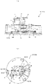
- the friction coefficient measurement apparatuses 100 (101) includes a friction measurement unit 1, a drive unit 2 which is a rotational driving source and so forth.
- the friction measurement unit 1 rotates a shaft 5, a disk-shaped main body 15 and a disk 17 which is a rotor by a motor 8 via gears 6 and 7.
- the main body 15 and the disk 17 are coupled together in a tangential direction of the main body 15 by a spring 16.
- a guide plate 18 and a pen holder 19 which is slidable in a radius direction are disposed on the disk 17.
- the pen holder 19 is coupled to the disk 17 by a spring 20.
- a pen 21 ( FIG. 1 ) used for recording measured values on a recording paper 27 is disposed on the center of the pen holder 19.
- an arm 23 is attached to the disk 17 on the side (on the left side in FIG. 2 ) opposite to the guide plate 18 and the arm 23 is coupled to a damper 24.
- the damper 24 is fixed to the main body 15 and functions as a damping device which damps a torsional vibration generated by the disk 17 and the spring 20.
- the road surface friction measuring rubber attached strips 30 (50) are attached to a lower surface of the main body 15 on the same circumference, for example, at three positions.
- the acceleration which works in the stop direction also acts to the disk 17 which rotates by being coupled with the main body 15 via the spring 16 in association with the above-mentioned operation.
- torsion corresponding to the magnitude of the frictional force between the road surface 26 and the friction measuring rubber 30B (50B) is generated between the main body 15 and the disk 17.
- the main body 15 and the disk 17 rotate in synchronization with each other at mutual relative positions where elastic force of the spring 16 and the friction force acting to the friction measuring rubber 30B (50B) are well-balanced.
- a friction coefficient ⁇ of the road surface 26 which is determined in accordance with a tangential velocity V measured by the friction coefficient measurement apparatus 100 (101) is proportional to a relative torsion angle ⁇ between the main body 15 and the disk 17 and it is possible to obtain the friction coefficient ⁇ by measuring the relative torsion angle ⁇ .
- a tangential velocity V (the measured velocity V) of the friction measurement rubber 30B (50B) as a function of a displacement amount S ( FIG. 2 ) in the radius direction of the spring 20.
- a relation between the tangential velocity V of the friction measuring rubber 30B (50B) of the road surface friction measuring rubber attached strip 30 (50) and the displacement amount S of the spring 20 and a relation between the friction coefficient ⁇ and the relative torsion angle ⁇ are calibrated in advance and thereby it is possible to automatically record the friction coefficient ⁇ of the road surface 26 and the relative velocity V on the recording paper 27 and it is possible to obtain a change in friction coefficient ⁇ ranging from a high velocity to a low velocity by one-time measurement.
- the friction measuring rubber 30B (50B) of the road surface friction measuring rubber attached strip 30 (50) is the consumption article. Accordingly, when measurement of the road surface friction is repetitively performed and the rubber is worn down due to the friction between the rubber 30B (50B) and the road surface 26, it is requested to replace the road surface friction measuring rubber attached strip 30 (50) that the friction measuring rubber 30B (50B) thereof has been worn down with the new one.
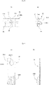
- the part A in FIG. 2 is a place where the road surface friction measuring rubber attached strip 30 (50) is attached to the disk-shaped main body 15 of the friction coefficient measurement apparatus 100 (101) and the attaching bolt 31 is provided on the attachment place A.
- the attaching bolt 31 is screwed into a holder 35 which is fixed to the main body 15 (see FIG. 1 and FIG. 2 : not illustrated in FIG. 3 ) and thereby attaches the road surface friction measuring rubber attached strip 30 (50) (not illustrated in FIG. 3 ) (to the main body 15).
- a symbol 36 denotes a bolt which fixes the holder 35 to the main body 15 side.
- a rubber attached trip attachment part 35A is formed on the center (the center in a crosswise direction in FIG. 3A ) of the holder 35.
- Parts 35B on the both sides of the rubber attached strip attachment part 35A are formed as members of a uniform thickness.
- the thickness of the rubber attached strip attachment part 35A is not uniform as illustrated in FIG. 3B and the thickness is gradually reduced linearly from one end (a lower end in FIG. 3B ) toward the other end (an upper end in FIG. 3B ) .
- a screw hole 35C ( FIG. 3B ) is formed in the center (the center in the crosswise direction in FIG. 3A ) of the rubber attached strip attachment part 35A of the holder 35 so as to screw the attaching bolt 31 into the screw hole 35C.
- the rubber attached strip attachment part 35A is inclined relative to a bottom surface 35D (an attachment surface to the main body 15 side: extending in a vertical direction in FIG. 3B ) of the holder 35 as illustrated in FIG. 3B .
- the rubber attached strip holding magnet 34 is provided in the vicinity of the attaching bolt 31 (the attachment place A in FIG. 2 : under the attaching bolt 31 in FIG. 3A and FIG. 3B ) and attracts the road surface friction measuring rubber attached strip 30 (50) which is constructed by the magnetic body (for example, iron) other than the rubber part. Even in a case where the attaching bolt 31 has been detached (unscrewed) from the screw hole 35C, the road surface friction measuring rubber attached strip 30 (50) is attracted to the rubber attached strip holding magnet 34 and therefore separation (falling) of the road surface friction measuring rubber attached strip 30 (50) from the main body 15 is prevented.
- the rubber attached strip holding magnet 34 is embedded in the rubber attached strip attachment part 35A of the holder 35 and the shape thereof may be cylindrical as illustrated in Fig. 3A and Fig. 3B or may be rectangular parallelepiped (not illustrated).
- the friction measuring rubber 30B is attached to one end (a lower end in FIG. 4A and FIG. 4B ) of the road surface friction measuring rubber attached strip 30 by a well-known manner (for example, adhesion, welding and so forth) and the vicinity of the other end (an upper end in FIG. 4A and FIG. 4B ) of the road surface friction measuring rubber attached strip 30 is constructed as an attachment part to the main body 15 side.
- the road surface friction measuring rubber attached strip 30 that the friction measuring rubber 30B thereof has been worn down is exchanged with the new one (another road surface friction measuring rubber attached strip 30 that the friction measuring rubber 30B thereof is not worn down).
- the friction measuring rubber 30B is gradually increased in thickness toward a leading end (the rubber 30B side end: the lower end in FIG. 4B ) of the road surface friction measuring rubber attached strip 30 and has a sufficient thickness in the vicinity of the leading end thereof.
- the insertion opening 30A into which the attaching bolt 31 is to be inserted is formed in the attachment part in the vicinity of the other end of the road surface friction measuring rubber attached strip 30 (the end which is opposite to the end to which the rubber 30B is attached: the upper end in FIG. 4A ).
- the attaching bolt insertion opening 30A is formed into a shape obtained by overlapping the circles of different diameter sizes, the small-diameter circular part 30AB is disposed on the upper part (in FIG. 4A ) and the large-diameter circular part 30AA is disposed on the lower part (in FIG. 4A ).
- the diameter of the large-diameter circular part 30AA is set slightly larger than the diameter of the bolt head of the attaching bolt 31 and the diameter of the small-diameter circular part 30AB is set smaller than the diameter of the bolt head of the attaching bolt 31 and slightly larger than the diameter of the bolt shaft thereof.
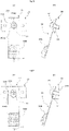
- the bolt head of the attaching bolt 31 is inserted into the large-diameter circular part 30AA of the attaching bolt insertion opening 30A in the road surface friction measuring rubber attached strip 30 and the road surface friction measuring rubber attached strip 30 is caught on (locked to) the attaching bolt 31.
- the vicinity of the end on the attachment part side (the side opposite to the rubber 30B) of the road surface friction measuring rubber attached strip 30 faces the rubber attached strip attachment part 35A of the holder 35.
- the rubber attached strip attachment part 35A is located behind the road surface friction measuring rubber attached strip 30. Since the rubber attached strip attachment part 35A is not illustrated in FIG. 5A , a leader line of the symbol "35A" is indicated by a dotted line).
- the road surface friction measuring rubbed attached strip 30 is moved (pulled) from the state illustrated in FIG. 5A in an arrow B direction (downward in FIG. 5A ) in FIG. 5A and the shaft of the attaching bolt 31 is positioned in the small-diameter circular part 30AB (the upper part of the opening 30A) of the attaching bolt insertion opening 30A (a state in FIG. 6A and FIG. 6B ).
- the attaching bolt 31 is fastened in the state in FIG. 6A and FIG. 6B and thereby the road friction measuring rubber attached strip 30 is attached to the main body 15 of the friction coefficient measurement apparatus 100 via the holder 35.
- the attaching bolt 31 and the rubber attached strip attachment part 35A of the holder 35 are disposed so as to be inclined relative to the bottom surface 35D which is the attachment surface of the holder 35 to the main body 15 side as mentioned above with reference to FIG. 3B .
- FIG. 6B which illustrates a state where the road surface friction measuring rubber attached strip 30 is attached to the holder 35
- the friction measuring rubber 30B which is provided on a leading end of the road surface friction measuring rubber attached strip 30 is disposed closer to the not illustrated road surface relative to the attachment surface (the bottom surface 35D of the holder 35) on the main body 15 side.
- the left side in FIG. 6B is the road surface side.
- the attaching bolt 31 When detaching the road surface friction measuring rubber attached strip 30 that the friction measurement rubber 30B thereof has been worn down, the attaching bolt 31 is loosened (unscrewed) in a range that the attaching bolt 31 is not detached from the holder 35 in FIG. 6A . Then, the road surface friction measuring rubber attached strip 30 is moved in an arrow C direction in Fig. 6A (upward in FIG. 6A ) so as to position the bolt head of the attaching bolt 31 in the large-diameter circular part 30AA of the attaching bolt insertion opening 30A as illustrated in FIG.5A . Then, the road surface friction measuring rubber attached strip 30 is moved (pulled up) in a direction vertical to the drawing of FIG.
- the attaching bolt 31 is held in a state of being not detached from the holder 35 (in a state of being screwed into the holder 35) and therefore it is not requested to perform the work of unscrewing the attaching bolt 31, detaching the attaching bolt 31 and then again screwing the attaching bolt 31 into the holder 35 (after the road surface friction measuring rubber attached strip 30 has been attached or detached). Therefore, it is not requested to separately provide the space for storing the attaching bolt 31 which has been detached from the main body 15 side while performing the work of replacing the road surface friction measuring rubber attached strip 30 with the new one and also management man-day for provision of the space is not taken.
- the attaching bolt 31 since the attaching bolt 31 is in a state of being screwed to the main body 15 side, the attaching bolt 31 does not fall from the main body 15 side and there is no fear of losing the attaching bolt 31 even in the night work.
- the road surface friction measuring rubber attached strip 30 is attached to the main body 15 of the friction coefficient measurement apparatus 100 via the holder 35, it is possible to select a distance between the friction measuring rubber 30B and the road surface 26 and a contact angle of the friction measuring rubber 30B relative to the road surface 26 by appropriately setting the inclination of the bottom surface 35D (the attachment surface) of the rubber attached strip attachment part 35A of the holder 35.
- the spring washer 32 (the existing spring washer) for anti-loosening the attaching bolt 31 is provided (see FIG. 8 ).
- the rubber attached strip fall prevention washer 33 is provided as illustrated in FIG. 7 and FIG. 8 .
- the rubber attached strip fall prevention washer 33 has the main body part which is annular as a whole and the notch 33A is formed in one part of the main body part in its circumferential direction. Then, the plurality (four) of projections 33B which project outward in the radius direction are formed on the main body part at equally separated positions in its circumferential direction.
- the opening size L1 of the notch 33A is set (slightly) smaller than the outer diameter of the shaft of the attaching bolt 31 and the distance L2 between the leading ends of the two projections 33B which are disposed at mutually facing positions is set larger than the diameter of the large-diameter circular part 30AA (see FIG. 4A ) of the attaching bolt insertion opening 30A in the road surface friction measuring rubber attached strip 30.
- the diameter of the inner circumferential surface of the rubber attached strip fall prevention washer 33 is set the same as the diameter of the inner circumferential surface of the existing spring washer 32.
- the rubber attached strip fall prevention washer 33 is interposed between the existing spring washer 32 and the bolt head of the attaching bolt 31. Then, the rubber attached strip fall prevention washer 33 is set to a size which makes it possible to nip and hold the rubber attached strip fall prevention washer 33 by the existing spring washer 32 and the bolt head of the attaching bolt 31.
- the rubber attached strip fall prevention washer 33 and the existing spring washer 32 are interposed between the bolt head of the attaching bolt 31 and the road surface friction measuring rubber attached strip 30 and the rubber attached strip fall prevention washer 33 is interposed between the existing spring washer 32 and the bolt head of the attaching bolt 31.
- the notch 33A ( FIG. 7 ) is pressed in a diameter expanding direction and is elastically deformed to such an extent that the opening size L1 of the notch 33A becomes larger than the diameter size of the shaft (the bolt shaft) of the attaching bolt 31 and the shaft of the attaching bolt 31 is inserted through the notch 33A.
- the maximum distance L2 between the leading ends of the two facing projections 33B of the rubber attached strip fall prevention washer 33 is set larger than the diameter of the large-diameter circular part 30AA of the attaching bolt insertion opening 30A in the road surface friction measuring rubber attached strip 30. Therefore, even in a case where the road surface friction measuring rubber attached strip 30 is in a state of being about to fall (upward in FIG. 8 ), the projections 33B are caught in the attaching bolt insertion opening 30A in the road surface friction measuring rubber attached strip 30.
- the road surface friction measuring rubber attached strip 30 does not drop out of the attaching bolt 31 or does not fall downward.
- the friction coefficient measurement apparatus 101 according to the second embodiment is different from the friction coefficient measurement apparatus 100 according to the first embodiment in the constructions of the road surface friction measuring rubber attached strip 50.
- the friction coefficient measurement apparatus 101 according to the second embodiment does not include the rubber attached strip fall prevention washer 33 in the first embodiment.
- the friction measuring rubber 50B is attached to one end (the lower end in FIG. 9A and FIG. 9B ) of the road surface friction measuring rubber attached strip 50 used in the second embodiment by the well-known manner (for example, adhesion, welding and so forth) .
- the vicinity of the other end (the upper end in FIG. 9A and FIG. 9B ) of the road surface friction measuring rubber attached strip 50 is constructed as an attachment part to the main body 15 side.
- the friction measuring rubber 50B according to the second embodiment has constructions and characteristics which are the same as those of the friction measuring rubber 30B of the road surface friction measuring rubber attached strip 30 according to the first embodiment.
- the road surface friction measuring rubber attached strip 50 that the friction measuring rubber 50B thereof has been worn down is replaced with the new one (another road friction measuring rubber attached strip 50 that the friction measuring rubber 50B thereof is not worn down.
- the attaching bolt insertion slit 50A into which the attaching bolt 31 is to be inserted is formed in the attachment part in the vicinity of the other end (the end which is opposite to the end that the friction measuring rubber 50B is attached: the upper end in FIG. 9A ) of the road surface friction measuring rubber attached strip 50.
- the attaching bolt insertion slit 50A is formed from one side surface (a right side surface in FIG. 9A ) of the road surface friction measuring rubber attached strip 50 toward the leftward center side and is formed in a direction vertical to a longitudinal direction of the road surface friction measuring rubber attached strip 50.
- the attaching bolt insertion slit 50A includes an insertion part 50AA which is formed from one side surface (the right side surface in FIG. 9A ) of the road surface friction measuring rubber attached strip 50 toward the center side (leftward in FIG. 9A ) up to the widthways center (of the road surface friction measuring rubber attached strip 50) having a predetermined width size and a semicircular central part 50AB which is formed contiguously to the insertion part 50AA and has a predetermined diameter size on the widthways center (of the road surface friction measuring rubber attached strip 50).
- both of the width size of the insertion part 50AA and the diameter size of the central part 50AB of the attaching bolt insertion slit 50A are set sizes which are smaller than the diameter of the bolt head of the attaching bolt 31 and slightly larger than the diameter of the bolt shaft thereof.
- the road surface friction measuring rubber attached strip 50 is attached to the main body 15 (see FIG. 1 and FIG. 2 ) of the friction coefficient measurement apparatus 101 via the holder 35 which is the same as that which has been mentioned above with reference to FIG. 3 and so forth similarly to the first embodiment.
- the shaft of the attaching bolt 31 is inserted through (the end opening of) the insertion part 50AA of the attaching bolt insertion slit 50A in the road surface friction measuring rubber attached strip 50 as illustrated in FIG. 10 .
- the attaching bolt 31 is in a state of being loosened to such an extent that it does not detach from the holder 35 (being fixed to the main body 15).
- the road surface friction measuring rubber attached strip 50 is moved in an arrow D direction (rightward in FIG. 10A ) in FIG. 10A relative to the attaching bolt 31 and the shaft of the attaching bolt 31 is relatively moved leftward along the insertion part 50AA of the attaching bolt insertion slit 50A so as to position the shaft of the attaching bolt 31 on the widthways center of the road surface friction measuring rubber attached strip 50.
- (the shaft of) the attaching bolt 31 abuts on the center-side end (that is, the end of the center part 50AB) of the attaching bolt insertion slit 50A and is positioned.
- the road surface friction measuring rubber attached strip 50 is attached to the main body 15 of the friction coefficient measurement apparatus 101 via the holder 35 by fastening the attaching bolt 31 in the state in FIG. 11A and FIG. 11B .
- the rubber attached strip holding magnet 34 is embedded in the rubber attached strip attachment part 35A of the holder 35 and the road surface friction measuring rubber attached strip 50 whose part other than the friction measuring rubber 50B is constructed by the magnetic body is attracted to the rubber attached strip holding magnet 34 as illustrated in FIG. 10A, FIG. 10B, FIG. 11A and FIG. 11B similarly to the first embodiment, separation of the road surface friction measuring rubber attached strip 50 from the main body 15 side is prevented.
- the attaching bolt 31 When detaching the road surface friction measuring rubber attached strip 50 that the friction measuring rubber 50B thereof has been worn down from the main body 15, the attaching bolt 31 is loosened (unscrewed) in a range that the attaching bolt 31 is not detached from the holder 35 in FIG. 11A and FIG. 11B . Then, the road surface friction measuring rubber attached strip 50 is moved in an arrow E direction (leftward in FIG. 11A ) in FIG. 11A and the shaft of the attaching bolt 31 is detached from the attaching bolt insertion slit 50A in the road surface friction measuring rubber attached strip 50.
- detachment is performed while avoiding interference with the part 35B which is larger in thickness than the rubber attached strip attachment part 35A by pulling upward the leftside end of the road surface friction measuring rubber attached strip 50 in the direction vertical to the drawing and in the spectator-side direction.
- the friction coefficient measurement apparatus 100 (101) includes the inclinometer 41.
- An article on the market for example, a brand name "DS Series" manufactured by NKK SWITCHES CO. LTD.
- NKK SWITCHES CO. LTD. may be used as the inclinometer 41.
- the inclinometer 41 has the function of measuring the inclination of the whole friction coefficient measurement apparatus 100 (101). A measurement result obtained from the inclinometer 41 is sent to the electromagnetic brake 42 via a not illustrated signal transfer line.
- the driving motor 8 rotates the friction measurement unit 1 via the gears 6 and 7 and the shaft 5. Then, the road surface friction measuring rubber attached strips 30 (50) are attached onto the lower surface of the main body 15 of the friction measurement unit 1, for example, at three positions.
- the electromagnetic brake 42 has the function that in a case where the inclination of the friction coefficient measurement apparatus 100 (101) which is at least a predetermined angle has been measured by the inclinometer 41 in a state where the friction coefficient measurement apparatus 100 (101) is in operation, (the electromagnetic brake 42) operates and stops the operation of the friction coefficient measurement apparatus 100 (101).
- the electromagnetic brake 42 also has the function that in a case where the friction coefficient measurement apparatus 100 (101) which is in operation has been lifted manually, the electromagnetic brake 42 operates and stops the operation of the friction coefficient measurement apparatus 100 (101).
- the friction coefficient measurement apparatus 100 (101) includes the counter 43.
- the counter 43 has the function of measuring and displaying the number of operations or the number of measurements of the friction coefficient measurement apparatus 100 (101).
- the number of operations or the number of measurements which is displayed on the counter 43 serves as the index for indicating to what extent the friction measuring rubber 30B (50B) of the road surface friction measuring rubber attached strip 30 (50) in the friction coefficient measurement apparatus 100 (101) is worn down and it is possible for a user of the friction coefficient measurement apparatus 100 (101) to grasp the timing of replacing the road friction measuring rubber attached strip 30 (50) with the new one.
- the friction coefficient measurement apparatus 100 (101) includes the satellite positioning system 44 (for example, the global positioning system: GPS). Although illustration is omitted, position information of the friction coefficient measurement apparatus 100 (101) determined by the satellite positioning system 44 is sent to a processing device in the friction coefficient measurement apparatus 100 (101) or an externally disposed processing system and thereby it becomes possible to accurately determine the position where the friction coefficient has been measured by the friction coefficient measurement 100 (101).
- the satellite positioning system 44 for example, the global positioning system: GPS
- the friction coefficient measurement apparatus 100 (101) also includes the road surface temperature measurement device 45.
- the road surface temperature measurement device 45 has the function of measuring the road surface temperature when measuring the friction coefficient of the road surface. Therefore, it is possible to determine the accurate friction coefficient by analyzing the influence of the road surface temperature imposed on the friction coefficient of the road surface and taking the road surface temperature into consideration.
Landscapes
- Engineering & Computer Science (AREA)
- Automation & Control Theory (AREA)
- Physics & Mathematics (AREA)
- Health & Medical Sciences (AREA)
- Life Sciences & Earth Sciences (AREA)
- Chemical & Material Sciences (AREA)
- Analytical Chemistry (AREA)
- Biochemistry (AREA)
- General Health & Medical Sciences (AREA)
- General Physics & Mathematics (AREA)
- Immunology (AREA)
- Pathology (AREA)
- General Engineering & Computer Science (AREA)
- Mechanical Engineering (AREA)
- A Measuring Device Byusing Mechanical Method (AREA)
- Force Measurement Appropriate To Specific Purposes (AREA)
Claims (7)
- Appareil de mesure de coefficient de frottement (100) pour mesurer un frottement entre une bande fixée à un caoutchouc de mesure de frottement de surface de route (30) et une surface de route (26), l'appareil de mesure (100) comprenant :une bande fixée à un caoutchouc de mesure de frottement de surface de route (30) qui est une bande à laquelle un caoutchouc de mesure de frottement de surface de route (30B) est fixé ;un boulon de fixation (31) qui fixe la bande fixée à un caoutchouc de mesure de frottement de surface de route (30) à une partie de l'appareil de mesure de coefficient de frottement ;une rondelle-ressort anti-desserrage (32) pour empêcher le desserrage du boulon de fixation (31) et de la tête de boulon du boulon de fixation (31) ; etune ouverture d'insertion de boulon de fixation (30A) formée dans la bande fixée à un caoutchouc de mesure de frottement de surface de route (30) ; caractérisé en ce que :l'ouverture d'insertion de boulon de fixation (30A) présente une forme formée par des cercles se chevauchant de différentes tailles de diamètre, un diamètre d'une partie circulaire de grand diamètre (30AA) est établi plus grand par rapport à un diamètre d'une tête de boulon (31) du boulon de fixation et un diamètre d'une partie circulaire de petit diamètre (30AB) est établi plus petit par rapport au diamètre de la tête de boulon du boulon de fixation (31) et plus grand par rapport à un diamètre d'une tige de boulon ; etune rondelle antichute de bande fixée à un caoutchouc (33) est interposée entre la rondelle-ressort anti-desserrage (32) de boulon de fixation et la tête de boulon du boulon de fixation (31), la rondelle antichute de bande fixée à un caoutchouc (33) est formée en une forme annulaire, une encoche (33A) est formée dans celle-ci et une pluralité de saillies (33B) qui font saillie vers l'extérieur dans une direction radiale sont formées sur celle-ci, une taille d'ouverture (L1) de ladite encoche (33A) est établie plus petite par rapport à un diamètre externe de la tige du boulon de fixation (31) et une distance maximale (L2) entre les extrémités avant des saillies (33B) est établie plus grande par rapport au diamètre de la partie circulaire de grand diamètre (30AA) dans l'ouverture d'insertion de boulon de fixation (30A) formée dans la bande fixée à un caoutchouc de mesure de frottement de surface de route (30), et l'encoche (33A) dans la rondelle antichute de bande fixée à un caoutchouc (33) peut être ouverte de force manuellement par déformation élastique pour permettre à la tige de boulon du boulon de fixation (31) d'être insérée dans l'encoche ouverte de force, après quoi la taille de l'ouverture de l'encoche retournera dans un état dans lequel elle est inférieure à la taille de diamètre de la tige de boulon.
- Appareil de mesure de coefficient de frottement (101) pour mesurer un frottement entre une bande fixée à un caoutchouc de mesure de frottement de surface de route (30) et une surface de route (26), l'appareil de mesure (101) comprenant :une bande fixée à un caoutchouc de mesure de frottement de surface de route (50) qui est une bande à laquelle un caoutchouc de mesure de frottement de surface de route (50B) est fixé ; etun boulon de fixation (31) qui fixe la bande fixée à un caoutchouc de mesure de frottement de surface de route (50) à une partie de l'appareil de mesure de coefficient de frottement (101) ;caractérisé en ce que :
une fente d'insertion de boulon de fixation (50A) est formée dans la bande fixée à un caoutchouc de mesure de frottement de surface de route (50), la fente d'insertion de boulon de fixation (50A) est formée à partir d'une surface latérale vers le côté central de la bande fixée à un caoutchouc de mesure de frottement de surface de route (50), la fente d'insertion de boulon de fixation (50A) est établie à une taille de largeur qui est inférieure à un diamètre d'une tête de boulon du boulon de fixation (31) et qui est supérieure à un diamètre d'une tige de boulon de celui-ci, et est pourvue d'une partie centrale semi-circulaire (50AB) formée de manière contiguë à une partie d'insertion (50AA), et une taille de diamètre de la partie centrale semi-circulaire (50AB) est inférieure au diamètre de la tête de boulon du boulon de fixation (31) et est supérieure au diamètre de la tige de boulon du boulon de fixation (31). - Appareil de mesure de coefficient de frottement (100; 101) selon la revendication 1 ou 2, dans lequel
la bande fixée à un caoutchouc de mesure de frottement de surface de route (30 ; 50) est faite d'un matériau magnétique et un aimant de maintien de bande fixé à un caoutchouc (34) est fourni à proximité du boulon de fixation (31). - Appareil de mesure de coefficient de frottement (100 ; 101) selon l'une quelconque des revendications 1 à 3, comprenant en outre un inclinomètre (41) étant configuré pour mesurer une inclinaison.
- Appareil de mesure de coefficient de frottement (100 ; 101) selon l'une quelconque des revendications 1 à 4, comprenant en outre un compteur (43).
- Appareil de mesure de coefficient de frottement (100 ; 101) selon l'une quelconque des revendications 1 à 5, comprenant en outre un système de positionnement par satellite (44).
- Appareil de mesure de coefficient de frottement (100 ; 101) selon l'une quelconque des revendications 1 à 6, comprenant en outre un dispositif de mesure de température de surface de route (45) configuré pour mesurer une température de surface de route.
Applications Claiming Priority (2)
| Application Number | Priority Date | Filing Date | Title |
|---|---|---|---|
| JP2016252341 | 2016-12-27 | ||
| JP2017095722A JP6907019B2 (ja) | 2016-12-27 | 2017-05-12 | 摩擦係数計測装置 |
Publications (2)
| Publication Number | Publication Date |
|---|---|
| EP3346257A1 EP3346257A1 (fr) | 2018-07-11 |
| EP3346257B1 true EP3346257B1 (fr) | 2022-04-27 |
Family
ID=60473334
Family Applications (1)
| Application Number | Title | Priority Date | Filing Date |
|---|---|---|---|
| EP17203416.7A Active EP3346257B1 (fr) | 2016-12-27 | 2017-11-23 | Appareils de mesure du coefficient de friction |
Country Status (2)
| Country | Link |
|---|---|
| US (1) | US10545086B2 (fr) |
| EP (1) | EP3346257B1 (fr) |
Families Citing this family (2)
| Publication number | Priority date | Publication date | Assignee | Title |
|---|---|---|---|---|
| US11435244B2 (en) * | 2017-11-30 | 2022-09-06 | Koc Universitesi | Force sensor for measuring static and dynamic friction coefficients |
| CN116026718B (zh) * | 2023-01-09 | 2024-01-02 | 赤峰吉隆矿业有限责任公司 | 一种提升机闸瓦磨损监测系统 |
Family Cites Families (11)
| Publication number | Priority date | Publication date | Assignee | Title |
|---|---|---|---|---|
| US3392427A (en) | 1966-12-27 | 1968-07-16 | Irving Air Chute Co Inc | Anchoring device |
| JPS5357082A (en) * | 1976-11-04 | 1978-05-24 | Hironari Abe | Device for measuring coefficient of friction on road surface |
| JPS5723212A (en) | 1980-07-17 | 1982-02-06 | Matsushita Electric Industrial Co Ltd | Method of producing solid electrolytic condenser |
| GB8918303D0 (en) * | 1989-08-10 | 1989-09-20 | Lucas Ind Plc | Monitoring and predicting road vehicle/road surface conditions |
| US6123314A (en) | 1994-11-30 | 2000-09-26 | Lockheed Martin Corporation | Quick mounting mechanism and method |
| US6401576B1 (en) * | 2001-01-24 | 2002-06-11 | Fu-Hsiung Wu | Hand tool |
| US20040187556A1 (en) | 2002-05-22 | 2004-09-30 | Hironari Abe | Method for measuring coefficient of friction |
| US6979775B2 (en) * | 2003-07-25 | 2005-12-27 | Ritter Bryan D | Security apparatus and method |
| FR2897909A1 (fr) | 2006-02-24 | 2007-08-31 | Valeo Systemes Dessuyage | Dispositif de fixation reglable d'un module mecanique et/ou electrique sur un support |
| US7784857B2 (en) | 2007-01-29 | 2010-08-31 | Toyota Motor Engineering & Manufacturing North America, Inc. | Fastener assembly |
| US9983139B2 (en) * | 2014-11-10 | 2018-05-29 | Donald Channing Cooper | Modular illumination and sensor chamber |
-
2017
- 2017-11-02 US US15/801,758 patent/US10545086B2/en active Active
- 2017-11-23 EP EP17203416.7A patent/EP3346257B1/fr active Active
Also Published As
| Publication number | Publication date |
|---|---|
| EP3346257A1 (fr) | 2018-07-11 |
| US20180202917A1 (en) | 2018-07-19 |
| US10545086B2 (en) | 2020-01-28 |
Similar Documents
| Publication | Publication Date | Title |
|---|---|---|
| EP3346257B1 (fr) | Appareils de mesure du coefficient de friction | |
| CA2731249C (fr) | Frein a disque, en particulier pour vehicule utilitaire | |
| Beeler et al. | Observed source parameters for dynamic rupture with non-uniform initial stress and relatively high fracture energy | |
| US20160280200A1 (en) | A device for measuring the thickness of automotive disc brake rotors | |
| BR112016002447B1 (pt) | dispositivo para monitorar pneus para rodas de veículos, pneu para rodas de veículo, e, método para instalar uma unidade eletrônica de um pneu para rodas de veículos | |
| US6957498B2 (en) | Brake drum caliper | |
| CN110537034B (zh) | 组合式地检测特别是机动车的制动设备的部件的磨损 | |
| CN108037316B (zh) | 基于性能指标测评加速度计可靠性的设备及方法 | |
| JP6907019B2 (ja) | 摩擦係数計測装置 | |
| US11281162B2 (en) | Shock indicator for watches | |
| WO2009022766A1 (fr) | Manomètre pour dispositif de mesure de pression | |
| WO2021049338A1 (fr) | Outil de coupe, système de coupe, procédé de traitement et programme de traitement | |
| US6176636B1 (en) | Two-component bracket and drive washer combination for automatically setting an air gap | |
| US5951191A (en) | Washer and bracket combination for automatically setting an air gap | |
| JP2019194524A (ja) | すべり抵抗係数測定装置 | |
| CN101733679B (zh) | 寻边器 | |
| EP1691109A2 (fr) | Tendeur de courroie integrée | |
| CN208885284U (zh) | 振动测量装置、隧道掘进机及刀盘振动测量系统 | |
| US10168136B2 (en) | Clearance gage | |
| US20100314203A1 (en) | Method for the assembly of a wear indicator on a brake | |
| CN208833411U (zh) | 执行器损耗参数测试系统 | |
| US3790951A (en) | Apparatus for measuring and recording acceleration forces | |
| CN223623526U (zh) | 一种用于定位螺纹外露长度的装置 | |
| CN223319908U (zh) | 一种带有定位结构的温度传感器探头 | |
| Fumi et al. | A novel in-vehicle real-time brake-monitoring system |
Legal Events
| Date | Code | Title | Description |
|---|---|---|---|
| PUAI | Public reference made under article 153(3) epc to a published international application that has entered the european phase |
Free format text: ORIGINAL CODE: 0009012 |
|
| STAA | Information on the status of an ep patent application or granted ep patent |
Free format text: STATUS: THE APPLICATION HAS BEEN PUBLISHED |
|
| AK | Designated contracting states |
Kind code of ref document: A1 Designated state(s): AL AT BE BG CH CY CZ DE DK EE ES FI FR GB GR HR HU IE IS IT LI LT LU LV MC MK MT NL NO PL PT RO RS SE SI SK SM TR |
|
| AX | Request for extension of the european patent |
Extension state: BA ME |
|
| STAA | Information on the status of an ep patent application or granted ep patent |
Free format text: STATUS: REQUEST FOR EXAMINATION WAS MADE |
|
| 17P | Request for examination filed |
Effective date: 20190111 |
|
| RBV | Designated contracting states (corrected) |
Designated state(s): AL AT BE BG CH CY CZ DE DK EE ES FI FR GB GR HR HU IE IS IT LI LT LU LV MC MK MT NL NO PL PT RO RS SE SI SK SM TR |
|
| GRAP | Despatch of communication of intention to grant a patent |
Free format text: ORIGINAL CODE: EPIDOSNIGR1 |
|
| STAA | Information on the status of an ep patent application or granted ep patent |
Free format text: STATUS: GRANT OF PATENT IS INTENDED |
|
| INTG | Intention to grant announced |
Effective date: 20211125 |
|
| GRAS | Grant fee paid |
Free format text: ORIGINAL CODE: EPIDOSNIGR3 |
|
| GRAA | (expected) grant |
Free format text: ORIGINAL CODE: 0009210 |
|
| STAA | Information on the status of an ep patent application or granted ep patent |
Free format text: STATUS: THE PATENT HAS BEEN GRANTED |
|
| AK | Designated contracting states |
Kind code of ref document: B1 Designated state(s): AL AT BE BG CH CY CZ DE DK EE ES FI FR GB GR HR HU IE IS IT LI LT LU LV MC MK MT NL NO PL PT RO RS SE SI SK SM TR |
|
| REG | Reference to a national code |
Ref country code: GB Ref legal event code: FG4D |
|
| REG | Reference to a national code |
Ref country code: CH Ref legal event code: EP |
|
| REG | Reference to a national code |
Ref country code: DE Ref legal event code: R096 Ref document number: 602017056488 Country of ref document: DE |
|
| REG | Reference to a national code |
Ref country code: AT Ref legal event code: REF Ref document number: 1487293 Country of ref document: AT Kind code of ref document: T Effective date: 20220515 |
|
| REG | Reference to a national code |
Ref country code: IE Ref legal event code: FG4D |
|
| REG | Reference to a national code |
Ref country code: LT Ref legal event code: MG9D |
|
| REG | Reference to a national code |
Ref country code: NL Ref legal event code: MP Effective date: 20220427 |
|
| REG | Reference to a national code |
Ref country code: AT Ref legal event code: MK05 Ref document number: 1487293 Country of ref document: AT Kind code of ref document: T Effective date: 20220427 |
|
| PG25 | Lapsed in a contracting state [announced via postgrant information from national office to epo] |
Ref country code: NL Free format text: LAPSE BECAUSE OF FAILURE TO SUBMIT A TRANSLATION OF THE DESCRIPTION OR TO PAY THE FEE WITHIN THE PRESCRIBED TIME-LIMIT Effective date: 20220427 |
|
| PG25 | Lapsed in a contracting state [announced via postgrant information from national office to epo] |
Ref country code: SE Free format text: LAPSE BECAUSE OF FAILURE TO SUBMIT A TRANSLATION OF THE DESCRIPTION OR TO PAY THE FEE WITHIN THE PRESCRIBED TIME-LIMIT Effective date: 20220427 Ref country code: PT Free format text: LAPSE BECAUSE OF FAILURE TO SUBMIT A TRANSLATION OF THE DESCRIPTION OR TO PAY THE FEE WITHIN THE PRESCRIBED TIME-LIMIT Effective date: 20220829 Ref country code: NO Free format text: LAPSE BECAUSE OF FAILURE TO SUBMIT A TRANSLATION OF THE DESCRIPTION OR TO PAY THE FEE WITHIN THE PRESCRIBED TIME-LIMIT Effective date: 20220727 Ref country code: LT Free format text: LAPSE BECAUSE OF FAILURE TO SUBMIT A TRANSLATION OF THE DESCRIPTION OR TO PAY THE FEE WITHIN THE PRESCRIBED TIME-LIMIT Effective date: 20220427 Ref country code: HR Free format text: LAPSE BECAUSE OF FAILURE TO SUBMIT A TRANSLATION OF THE DESCRIPTION OR TO PAY THE FEE WITHIN THE PRESCRIBED TIME-LIMIT Effective date: 20220427 Ref country code: GR Free format text: LAPSE BECAUSE OF FAILURE TO SUBMIT A TRANSLATION OF THE DESCRIPTION OR TO PAY THE FEE WITHIN THE PRESCRIBED TIME-LIMIT Effective date: 20220728 Ref country code: FI Free format text: LAPSE BECAUSE OF FAILURE TO SUBMIT A TRANSLATION OF THE DESCRIPTION OR TO PAY THE FEE WITHIN THE PRESCRIBED TIME-LIMIT Effective date: 20220427 Ref country code: ES Free format text: LAPSE BECAUSE OF FAILURE TO SUBMIT A TRANSLATION OF THE DESCRIPTION OR TO PAY THE FEE WITHIN THE PRESCRIBED TIME-LIMIT Effective date: 20220427 Ref country code: BG Free format text: LAPSE BECAUSE OF FAILURE TO SUBMIT A TRANSLATION OF THE DESCRIPTION OR TO PAY THE FEE WITHIN THE PRESCRIBED TIME-LIMIT Effective date: 20220727 Ref country code: AT Free format text: LAPSE BECAUSE OF FAILURE TO SUBMIT A TRANSLATION OF THE DESCRIPTION OR TO PAY THE FEE WITHIN THE PRESCRIBED TIME-LIMIT Effective date: 20220427 |
|
| PG25 | Lapsed in a contracting state [announced via postgrant information from national office to epo] |
Ref country code: RS Free format text: LAPSE BECAUSE OF FAILURE TO SUBMIT A TRANSLATION OF THE DESCRIPTION OR TO PAY THE FEE WITHIN THE PRESCRIBED TIME-LIMIT Effective date: 20220427 Ref country code: PL Free format text: LAPSE BECAUSE OF FAILURE TO SUBMIT A TRANSLATION OF THE DESCRIPTION OR TO PAY THE FEE WITHIN THE PRESCRIBED TIME-LIMIT Effective date: 20220427 Ref country code: LV Free format text: LAPSE BECAUSE OF FAILURE TO SUBMIT A TRANSLATION OF THE DESCRIPTION OR TO PAY THE FEE WITHIN THE PRESCRIBED TIME-LIMIT Effective date: 20220427 Ref country code: IS Free format text: LAPSE BECAUSE OF FAILURE TO SUBMIT A TRANSLATION OF THE DESCRIPTION OR TO PAY THE FEE WITHIN THE PRESCRIBED TIME-LIMIT Effective date: 20220827 |
|
| REG | Reference to a national code |
Ref country code: DE Ref legal event code: R097 Ref document number: 602017056488 Country of ref document: DE |
|
| PG25 | Lapsed in a contracting state [announced via postgrant information from national office to epo] |
Ref country code: SM Free format text: LAPSE BECAUSE OF FAILURE TO SUBMIT A TRANSLATION OF THE DESCRIPTION OR TO PAY THE FEE WITHIN THE PRESCRIBED TIME-LIMIT Effective date: 20220427 Ref country code: SK Free format text: LAPSE BECAUSE OF FAILURE TO SUBMIT A TRANSLATION OF THE DESCRIPTION OR TO PAY THE FEE WITHIN THE PRESCRIBED TIME-LIMIT Effective date: 20220427 Ref country code: RO Free format text: LAPSE BECAUSE OF FAILURE TO SUBMIT A TRANSLATION OF THE DESCRIPTION OR TO PAY THE FEE WITHIN THE PRESCRIBED TIME-LIMIT Effective date: 20220427 Ref country code: EE Free format text: LAPSE BECAUSE OF FAILURE TO SUBMIT A TRANSLATION OF THE DESCRIPTION OR TO PAY THE FEE WITHIN THE PRESCRIBED TIME-LIMIT Effective date: 20220427 Ref country code: DK Free format text: LAPSE BECAUSE OF FAILURE TO SUBMIT A TRANSLATION OF THE DESCRIPTION OR TO PAY THE FEE WITHIN THE PRESCRIBED TIME-LIMIT Effective date: 20220427 Ref country code: CZ Free format text: LAPSE BECAUSE OF FAILURE TO SUBMIT A TRANSLATION OF THE DESCRIPTION OR TO PAY THE FEE WITHIN THE PRESCRIBED TIME-LIMIT Effective date: 20220427 |
|
| PLBE | No opposition filed within time limit |
Free format text: ORIGINAL CODE: 0009261 |
|
| STAA | Information on the status of an ep patent application or granted ep patent |
Free format text: STATUS: NO OPPOSITION FILED WITHIN TIME LIMIT |
|
| PG25 | Lapsed in a contracting state [announced via postgrant information from national office to epo] |
Ref country code: AL Free format text: LAPSE BECAUSE OF FAILURE TO SUBMIT A TRANSLATION OF THE DESCRIPTION OR TO PAY THE FEE WITHIN THE PRESCRIBED TIME-LIMIT Effective date: 20220427 |
|
| 26N | No opposition filed |
Effective date: 20230130 |
|
| PG25 | Lapsed in a contracting state [announced via postgrant information from national office to epo] |
Ref country code: SI Free format text: LAPSE BECAUSE OF FAILURE TO SUBMIT A TRANSLATION OF THE DESCRIPTION OR TO PAY THE FEE WITHIN THE PRESCRIBED TIME-LIMIT Effective date: 20220427 |
|
| PG25 | Lapsed in a contracting state [announced via postgrant information from national office to epo] |
Ref country code: MC Free format text: LAPSE BECAUSE OF FAILURE TO SUBMIT A TRANSLATION OF THE DESCRIPTION OR TO PAY THE FEE WITHIN THE PRESCRIBED TIME-LIMIT Effective date: 20220427 |
|
| REG | Reference to a national code |
Ref country code: CH Ref legal event code: PL |
|
| REG | Reference to a national code |
Ref country code: BE Ref legal event code: MM Effective date: 20221130 |
|
| PG25 | Lapsed in a contracting state [announced via postgrant information from national office to epo] |
Ref country code: LI Free format text: LAPSE BECAUSE OF NON-PAYMENT OF DUE FEES Effective date: 20221130 Ref country code: CH Free format text: LAPSE BECAUSE OF NON-PAYMENT OF DUE FEES Effective date: 20221130 |
|
| PG25 | Lapsed in a contracting state [announced via postgrant information from national office to epo] |
Ref country code: LU Free format text: LAPSE BECAUSE OF NON-PAYMENT OF DUE FEES Effective date: 20221123 |
|
| PG25 | Lapsed in a contracting state [announced via postgrant information from national office to epo] |
Ref country code: IE Free format text: LAPSE BECAUSE OF NON-PAYMENT OF DUE FEES Effective date: 20221123 |
|
| PG25 | Lapsed in a contracting state [announced via postgrant information from national office to epo] |
Ref country code: BE Free format text: LAPSE BECAUSE OF NON-PAYMENT OF DUE FEES Effective date: 20221130 |
|
| PG25 | Lapsed in a contracting state [announced via postgrant information from national office to epo] |
Ref country code: IT Free format text: LAPSE BECAUSE OF FAILURE TO SUBMIT A TRANSLATION OF THE DESCRIPTION OR TO PAY THE FEE WITHIN THE PRESCRIBED TIME-LIMIT Effective date: 20220427 |
|
| PG25 | Lapsed in a contracting state [announced via postgrant information from national office to epo] |
Ref country code: HU Free format text: LAPSE BECAUSE OF FAILURE TO SUBMIT A TRANSLATION OF THE DESCRIPTION OR TO PAY THE FEE WITHIN THE PRESCRIBED TIME-LIMIT; INVALID AB INITIO Effective date: 20171123 |
|
| PG25 | Lapsed in a contracting state [announced via postgrant information from national office to epo] |
Ref country code: CY Free format text: LAPSE BECAUSE OF FAILURE TO SUBMIT A TRANSLATION OF THE DESCRIPTION OR TO PAY THE FEE WITHIN THE PRESCRIBED TIME-LIMIT Effective date: 20220427 |
|
| PG25 | Lapsed in a contracting state [announced via postgrant information from national office to epo] |
Ref country code: MK Free format text: LAPSE BECAUSE OF FAILURE TO SUBMIT A TRANSLATION OF THE DESCRIPTION OR TO PAY THE FEE WITHIN THE PRESCRIBED TIME-LIMIT Effective date: 20220427 |
|
| PG25 | Lapsed in a contracting state [announced via postgrant information from national office to epo] |
Ref country code: TR Free format text: LAPSE BECAUSE OF FAILURE TO SUBMIT A TRANSLATION OF THE DESCRIPTION OR TO PAY THE FEE WITHIN THE PRESCRIBED TIME-LIMIT Effective date: 20220427 |
|
| PG25 | Lapsed in a contracting state [announced via postgrant information from national office to epo] |
Ref country code: MT Free format text: LAPSE BECAUSE OF FAILURE TO SUBMIT A TRANSLATION OF THE DESCRIPTION OR TO PAY THE FEE WITHIN THE PRESCRIBED TIME-LIMIT Effective date: 20220427 |
|
| PG25 | Lapsed in a contracting state [announced via postgrant information from national office to epo] |
Ref country code: BG Free format text: LAPSE BECAUSE OF FAILURE TO SUBMIT A TRANSLATION OF THE DESCRIPTION OR TO PAY THE FEE WITHIN THE PRESCRIBED TIME-LIMIT Effective date: 20220427 |
|
| PG25 | Lapsed in a contracting state [announced via postgrant information from national office to epo] |
Ref country code: BG Free format text: LAPSE BECAUSE OF FAILURE TO SUBMIT A TRANSLATION OF THE DESCRIPTION OR TO PAY THE FEE WITHIN THE PRESCRIBED TIME-LIMIT Effective date: 20220427 |
|
| PGFP | Annual fee paid to national office [announced via postgrant information from national office to epo] |
Ref country code: DE Payment date: 20251118 Year of fee payment: 9 |
|
| PGFP | Annual fee paid to national office [announced via postgrant information from national office to epo] |
Ref country code: GB Payment date: 20251118 Year of fee payment: 9 |
|
| PGFP | Annual fee paid to national office [announced via postgrant information from national office to epo] |
Ref country code: FR Payment date: 20251117 Year of fee payment: 9 |