EP3346478A1 - Système de condensateur et système électrique sous-marin le comprenant - Google Patents
Système de condensateur et système électrique sous-marin le comprenant Download PDFInfo
- Publication number
- EP3346478A1 EP3346478A1 EP17150678.5A EP17150678A EP3346478A1 EP 3346478 A1 EP3346478 A1 EP 3346478A1 EP 17150678 A EP17150678 A EP 17150678A EP 3346478 A1 EP3346478 A1 EP 3346478A1
- Authority
- EP
- European Patent Office
- Prior art keywords
- capacitor
- terminal
- current limiter
- inductive element
- coupled
- Prior art date
- Legal status (The legal status is an assumption and is not a legal conclusion. Google has not performed a legal analysis and makes no representation as to the accuracy of the status listed.)
- Granted
Links
- 239000003990 capacitor Substances 0.000 title claims abstract description 86
- 230000001939 inductive effect Effects 0.000 claims abstract description 36
- 238000004804 winding Methods 0.000 claims description 9
- 239000011104 metalized film Substances 0.000 claims description 5
- XLYOFNOQVPJJNP-UHFFFAOYSA-N water Substances O XLYOFNOQVPJJNP-UHFFFAOYSA-N 0.000 description 2
- 230000006378 damage Effects 0.000 description 1
- 239000010408 film Substances 0.000 description 1
- 230000004907 flux Effects 0.000 description 1
- 238000009434 installation Methods 0.000 description 1
- 238000000034 method Methods 0.000 description 1
Images

Classifications
-
- H—ELECTRICITY
- H01—ELECTRIC ELEMENTS
- H01G—CAPACITORS; CAPACITORS, RECTIFIERS, DETECTORS, SWITCHING DEVICES, LIGHT-SENSITIVE OR TEMPERATURE-SENSITIVE DEVICES OF THE ELECTROLYTIC TYPE
- H01G4/00—Fixed capacitors; Processes of their manufacture
- H01G4/38—Multiple capacitors, i.e. structural combinations of fixed capacitors
-
- H—ELECTRICITY
- H01—ELECTRIC ELEMENTS
- H01F—MAGNETS; INDUCTANCES; TRANSFORMERS; SELECTION OF MATERIALS FOR THEIR MAGNETIC PROPERTIES
- H01F27/00—Details of transformers or inductances, in general
- H01F27/28—Coils; Windings; Conductive connections
- H01F27/2804—Printed windings
-
- H—ELECTRICITY
- H01—ELECTRIC ELEMENTS
- H01F—MAGNETS; INDUCTANCES; TRANSFORMERS; SELECTION OF MATERIALS FOR THEIR MAGNETIC PROPERTIES
- H01F37/00—Fixed inductances not covered by group H01F17/00
-
- H—ELECTRICITY
- H01—ELECTRIC ELEMENTS
- H01G—CAPACITORS; CAPACITORS, RECTIFIERS, DETECTORS, SWITCHING DEVICES, LIGHT-SENSITIVE OR TEMPERATURE-SENSITIVE DEVICES OF THE ELECTROLYTIC TYPE
- H01G2/00—Details of capacitors not covered by a single one of groups H01G4/00-H01G11/00
- H01G2/14—Protection against electric or thermal overload
-
- H—ELECTRICITY
- H01—ELECTRIC ELEMENTS
- H01G—CAPACITORS; CAPACITORS, RECTIFIERS, DETECTORS, SWITCHING DEVICES, LIGHT-SENSITIVE OR TEMPERATURE-SENSITIVE DEVICES OF THE ELECTROLYTIC TYPE
- H01G4/00—Fixed capacitors; Processes of their manufacture
- H01G4/002—Details
- H01G4/224—Housing; Encapsulation
-
- H—ELECTRICITY
- H01—ELECTRIC ELEMENTS
- H01G—CAPACITORS; CAPACITORS, RECTIFIERS, DETECTORS, SWITCHING DEVICES, LIGHT-SENSITIVE OR TEMPERATURE-SENSITIVE DEVICES OF THE ELECTROLYTIC TYPE
- H01G4/00—Fixed capacitors; Processes of their manufacture
- H01G4/002—Details
- H01G4/228—Terminals
-
- H—ELECTRICITY
- H01—ELECTRIC ELEMENTS
- H01G—CAPACITORS; CAPACITORS, RECTIFIERS, DETECTORS, SWITCHING DEVICES, LIGHT-SENSITIVE OR TEMPERATURE-SENSITIVE DEVICES OF THE ELECTROLYTIC TYPE
- H01G4/00—Fixed capacitors; Processes of their manufacture
- H01G4/40—Structural combinations of fixed capacitors with other electric elements, the structure mainly consisting of a capacitor, e.g. RC combinations
-
- H—ELECTRICITY
- H01—ELECTRIC ELEMENTS
- H01F—MAGNETS; INDUCTANCES; TRANSFORMERS; SELECTION OF MATERIALS FOR THEIR MAGNETIC PROPERTIES
- H01F27/00—Details of transformers or inductances, in general
- H01F27/28—Coils; Windings; Conductive connections
- H01F27/2804—Printed windings
- H01F2027/2809—Printed windings on stacked layers
-
- H—ELECTRICITY
- H01—ELECTRIC ELEMENTS
- H01G—CAPACITORS; CAPACITORS, RECTIFIERS, DETECTORS, SWITCHING DEVICES, LIGHT-SENSITIVE OR TEMPERATURE-SENSITIVE DEVICES OF THE ELECTROLYTIC TYPE
- H01G4/00—Fixed capacitors; Processes of their manufacture
- H01G4/002—Details
- H01G4/005—Electrodes
- H01G4/015—Special provisions for self-healing
-
- H—ELECTRICITY
- H02—GENERATION; CONVERSION OR DISTRIBUTION OF ELECTRIC POWER
- H02H—EMERGENCY PROTECTIVE CIRCUIT ARRANGEMENTS
- H02H9/00—Emergency protective circuit arrangements for limiting excess current or voltage without disconnection
- H02H9/001—Emergency protective circuit arrangements for limiting excess current or voltage without disconnection limiting speed of change of electric quantities, e.g. soft switching on or off
- H02H9/002—Emergency protective circuit arrangements for limiting excess current or voltage without disconnection limiting speed of change of electric quantities, e.g. soft switching on or off limiting inrush current on switching on of inductive loads subjected to remanence, e.g. transformers
-
- H—ELECTRICITY
- H02—GENERATION; CONVERSION OR DISTRIBUTION OF ELECTRIC POWER
- H02H—EMERGENCY PROTECTIVE CIRCUIT ARRANGEMENTS
- H02H9/00—Emergency protective circuit arrangements for limiting excess current or voltage without disconnection
- H02H9/02—Emergency protective circuit arrangements for limiting excess current or voltage without disconnection responsive to excess current
- H02H9/021—Current limitation using saturable reactors
Definitions
- the present invention relates generally to a capacitor system and particularly to a capacitor system for subsea electrical systems.
- Capacitor systems are often used in energy distribution networks to provide capacitive reactive compensation and/or power factor correction. Capacitor systems are relatively inexpensive, usually easy and quick to install and can be deployed virtually anywhere in the network.
- components are immersed in a pressure compensated oil volume which is contained within a vessel or enclosure which can be of light-weight design as it does not need to withstand the high pressures encountered at water depths of several thousand meters.
- Pressure compensated means that the pressure inside the vessel is balanced to the ambient pressure. Thereby the ambient pressure may be very high, for example several hundred bar, but the differential pressure between the inside and the outside of the vessel or enclosure may be low, for example 0 bar to 2 bar.
- any component of the subsea circuitry will be exposed to pressures equivalent to the high ambient water pressure.
- self-healing properties of capacitors are impeded by such high pressures.
- self-healing capacitors are usually of the metalized film type.
- the film layers are pressed against each other by the pressure to which the capacitor is exposed, thereby influencing the self-healing properties considerably.
- the fault current being fed into a failure of a single capacitor may be too high to be handled by the self-healing mechanism and may also cause intolerable EMI to nearby components.
- a capacitor system comprising a first capacitor and a second capacitor having essentially the same capacitance and a current limiter.
- a first terminal of the first capacitor and a first terminal of the second capacitor are connectable to a first busbar.
- the second terminal of the first capacitor is coupled to a first terminal of the current limiter and the second terminal of the second capacitor is coupled to a second terminal of the current limiter.
- the current limiter has at least one third terminal connectable to a second busbar and comprises a first inductive element and a second inductive element having essentially the same inductance and being magnetically coupled with opposite polarity.
- the present invention also relates to a subsea electrical system comprising at least one such capacitor system immersed in a pressure compensated oil volume contained within a vessel or enclosure.
- a first terminal of the first inductive element is connected to the at least one third terminal of the current limiter and the second terminal of the first inductive element is connected to the first terminal of the current limiter while a first terminal of the second inductive element is connected to the second terminal of the current limiter and the second terminal of the second inductive element is connected to the at least one third terminal of the current limiter.
- first and/or second capacitor is a group of capacitors connected in parallel.
- the first and second inductive elements may for example be coupled air core coils or planar windings.
- Planar windings may for example be arranged in separate layers of a printed circuit board.
- the capacitors are of the metalized film type to facilitate self-healing.
- Fig. 1 there is shown an exemplary electrical system comprising three capacitor systems 100 constructed in accordance with the present invention which are connected to a first busbar 200 and a second busbar 300.
- first busbar 200 may bear ground potential and the second busbar 300 may be a DC-link busbar bearing the operating voltage.
- a capacitor system 100 in accordance with the present invention comprises two capacitors 110 and 120 having essentially the same capacitance.
- Capacitors 110 and 120 may be single capacitors as shown in Fig. 1 or may be constructed by connecting groups of capacitors in parallel (not shown).
- Capacitor system 100 further comprises a current limiter 130 comprising two inductors 131 and 132 which are coupled magnetically wherein the polarity of two inductors 131 and 132 is opposite.
- first terminal of first capacitor 110 and a first terminal of second capacitor 120 are connected to a first terminal of capacitor system 100 which in turn is connected to first busbar 200.
- the second terminal of first capacitor 110 is coupled to a first terminal 134 of current limiter 130 and the second terminal of second capacitor 120 is coupled to a second terminal of current limiter 130.
- Current limiter 130 has at least one third terminal 133 (which forms the second terminal of capacitor system 100) which is connected to second busbar 300.
- Current limiter 130 comprises a first inductive element 131 and a second inductive element 132 being magnetically coupled with opposite polarity and preferably having essentially the same inductance.
- capacitor system 100 could also be described as a parallel connection of two subsystems each composed of an inductor 131, 132 and a capacitor 110, 120 in series wherein the inductance of the inductors and the capacitance of the capacitors are essentially equal and wherein the inductors are magnetically coupled with opposite polarity.
- inductors 131, 132 elements In normal operation of capacitor system 100 the common mode currents in inductors 131, 132 elements will compensate each other because of the opposite polarity of inductors 131, 132. Thus the presence of inductors 131, 132 will have little or no influence, including EMI, on the impedance between the capacitors 110, 120 and other circuitry connected to busbars 200, 300.
- current limiter 130 has selective impedance depending on the current flow.
- a capacitor system 100 comprising such current limiter 130 is particularly useful if the capacitors are of the metalized film type as it limits the failure current and thus facilitates the self-healing process, prevents destruction of the failed capacitor and consequently ensures the continued operation of the capacitor.
- the latter is particularly important in environments where failed capacitors can only be retrieved and replaced at high cost, for example in subsea power grids. For such applications the additional cost of two magnetically coupled inductors is more than acceptable.
- the inductive elements 131, 132 may in embodiments be well-known wire coils preferably sharing the same magnetic or air core (not shown) but being arranged such that their polarity is opposite. Opposite polarity here means that in the normal operation of current limiter 130 the current flow through inductive elements 131, 132 is such that the corresponding magnetic fluxes are of opposite polarity such that ideally there is no resulting magnetic field outside of current limiter 130.
- inductive elements 131, 132 may be coils whose turns are arranged in opposite directions around a shared (air) core wherein inductive elements 131, 132 share one terminal on the same side/end of the core.
- inductive elements may be coils whose turns are arranged in the same direction around a shared core wherein one terminal of the first inductive element is coupled to the terminal of the second inductive element located at the opposite side/end of the core to form common terminal 133.
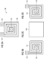
- inductive elements 131, 132 may comprise planar windings preferably sharing the same magnetic or air core and preferably arranged in separate layers of a printed circuit board as shown in Fig. 2
- Fig. 2 a current limiter 130 suitable for smaller currents is shown in detail.
- Fig. 2a shows the assembled three-layer current limiter 130 and Fig. 2b, 2c and 2d show the individual layers.
- Fig. 2b shows first inductive element 131 comprising a first (common) terminal 133 in the center of first inductive element 131, and a planar winding which extends spirally clockwise from first terminal 133 to second terminal 134 of first inductive element 131.
- Fig. 2c shows an insulating layer of a printed circuit board.
- Fig. 2d shows second inductive element 132 comprising a first (common) terminal 133 in the center of second inductive element 132, and a planar winding which extends spirally counterclockwise from first terminal 133 to second terminal 135 of second inductive element 132.
- Inductive elements 131, 132 share center terminal 133 and are arranged in concentric fashion as shown in Fig. 2a .
- the connection of both first terminals 133 of inductive elements 131, 132 may for example be standard via (not shown) extending from the layer shown in Fig. 2b through the insulating layer shown in Fig. 2c to the layer shown in Fig. 2d .
- While the present invention is particularly useful for use with metalized film type capacitors and in the subsea environment it may of course be applied in many other contexts where capacitors connected in parallel are required and where the current flow from a capacitor to its neighbor needs to be limited, for example in case of a fault.
Landscapes
- Engineering & Computer Science (AREA)
- Power Engineering (AREA)
- Microelectronics & Electronic Packaging (AREA)
- Manufacturing & Machinery (AREA)
- Fixed Capacitors And Capacitor Manufacturing Machines (AREA)
- Emergency Protection Circuit Devices (AREA)
Priority Applications (2)
| Application Number | Priority Date | Filing Date | Title |
|---|---|---|---|
| EP17150678.5A EP3346478B1 (fr) | 2017-01-09 | 2017-01-09 | Système de condensateur et système sous-marin le comprenant |
| US15/832,876 US10622158B2 (en) | 2017-01-09 | 2017-12-06 | Capacitor system |
Applications Claiming Priority (1)
| Application Number | Priority Date | Filing Date | Title |
|---|---|---|---|
| EP17150678.5A EP3346478B1 (fr) | 2017-01-09 | 2017-01-09 | Système de condensateur et système sous-marin le comprenant |
Publications (2)
| Publication Number | Publication Date |
|---|---|
| EP3346478A1 true EP3346478A1 (fr) | 2018-07-11 |
| EP3346478B1 EP3346478B1 (fr) | 2019-05-01 |
Family
ID=57758513
Family Applications (1)
| Application Number | Title | Priority Date | Filing Date |
|---|---|---|---|
| EP17150678.5A Active EP3346478B1 (fr) | 2017-01-09 | 2017-01-09 | Système de condensateur et système sous-marin le comprenant |
Country Status (2)
| Country | Link |
|---|---|
| US (1) | US10622158B2 (fr) |
| EP (1) | EP3346478B1 (fr) |
Cited By (1)
| Publication number | Priority date | Publication date | Assignee | Title |
|---|---|---|---|---|
| CN110661268A (zh) * | 2019-08-21 | 2020-01-07 | 内蒙古电力(集团)有限责任公司内蒙古电力科学研究院分公司 | 一种新能源汇集站点的动态无功补偿需求确定方法及系统 |
Citations (6)
| Publication number | Priority date | Publication date | Assignee | Title |
|---|---|---|---|---|
| US4219856A (en) * | 1977-03-11 | 1980-08-26 | Asea Aktiebolag | Protective device for capacitor bank |
| US20060214760A1 (en) * | 2005-03-22 | 2006-09-28 | Acutechnology Semiconductor Inc. | Air core inductive element on printed circuit board for use in switching power conversion circuitries |
| CN201364821Y (zh) * | 2009-03-02 | 2009-12-16 | 日新电机株式会社 | 电容器装置 |
| EP2975621A1 (fr) * | 2014-07-15 | 2016-01-20 | Siemens Aktiengesellschaft | Batterie de condensateur |
| EP2985852A1 (fr) * | 2014-08-14 | 2016-02-17 | Siemens Aktiengesellschaft | Système et procédé de surveillance de l'état et de contrôle d'un niveau de charge d'au moins un condensateur |
| US20160358717A1 (en) * | 2014-04-23 | 2016-12-08 | Richard Down Newberry | NEWBatERRY: Newberry Supercap-Battery Greenergy Storage Device |
Family Cites Families (10)
| Publication number | Priority date | Publication date | Assignee | Title |
|---|---|---|---|---|
| US2948852A (en) * | 1957-03-19 | 1960-08-09 | Philips Corp | Systems for detecting relative movements using ferro-resonant systems |
| US3231701A (en) * | 1962-09-14 | 1966-01-25 | Gen Electric | Capacitor protective system |
| US3348158A (en) * | 1964-11-18 | 1967-10-17 | Avco Corp | Temperature-compensated discriminator providing amplification |
| US3467888A (en) * | 1967-01-06 | 1969-09-16 | Herman B Wolf | Capacitor bank surge protection device |
| JP3058121B2 (ja) * | 1997-05-19 | 2000-07-04 | 日本電気株式会社 | プリント基板 |
| JPH1140915A (ja) * | 1997-05-22 | 1999-02-12 | Nec Corp | プリント配線板 |
| GB2509742A (en) * | 2013-01-11 | 2014-07-16 | Gridon Ltd | Fault current limiter |
| EP2884509B1 (fr) * | 2013-12-16 | 2019-08-28 | Siemens Aktiengesellschaft | Élimination de défaillances d'un condensateur à film autorégénérable |
| SE539392C2 (en) * | 2015-12-28 | 2017-09-12 | Scibreak Ab | Arrangement, system, and method of interrupting current |
| US10491181B2 (en) * | 2016-10-07 | 2019-11-26 | Murata Manufacturing Co., Ltd. | High-frequency filter and high-frequency module |
-
2017
- 2017-01-09 EP EP17150678.5A patent/EP3346478B1/fr active Active
- 2017-12-06 US US15/832,876 patent/US10622158B2/en not_active Expired - Fee Related
Patent Citations (6)
| Publication number | Priority date | Publication date | Assignee | Title |
|---|---|---|---|---|
| US4219856A (en) * | 1977-03-11 | 1980-08-26 | Asea Aktiebolag | Protective device for capacitor bank |
| US20060214760A1 (en) * | 2005-03-22 | 2006-09-28 | Acutechnology Semiconductor Inc. | Air core inductive element on printed circuit board for use in switching power conversion circuitries |
| CN201364821Y (zh) * | 2009-03-02 | 2009-12-16 | 日新电机株式会社 | 电容器装置 |
| US20160358717A1 (en) * | 2014-04-23 | 2016-12-08 | Richard Down Newberry | NEWBatERRY: Newberry Supercap-Battery Greenergy Storage Device |
| EP2975621A1 (fr) * | 2014-07-15 | 2016-01-20 | Siemens Aktiengesellschaft | Batterie de condensateur |
| EP2985852A1 (fr) * | 2014-08-14 | 2016-02-17 | Siemens Aktiengesellschaft | Système et procédé de surveillance de l'état et de contrôle d'un niveau de charge d'au moins un condensateur |
Cited By (2)
| Publication number | Priority date | Publication date | Assignee | Title |
|---|---|---|---|---|
| CN110661268A (zh) * | 2019-08-21 | 2020-01-07 | 内蒙古电力(集团)有限责任公司内蒙古电力科学研究院分公司 | 一种新能源汇集站点的动态无功补偿需求确定方法及系统 |
| CN110661268B (zh) * | 2019-08-21 | 2022-03-04 | 内蒙古电力(集团)有限责任公司内蒙古电力科学研究院分公司 | 一种新能源汇集站点的动态无功补偿需求确定方法及系统 |
Also Published As
| Publication number | Publication date |
|---|---|
| US20180197684A1 (en) | 2018-07-12 |
| EP3346478B1 (fr) | 2019-05-01 |
| US10622158B2 (en) | 2020-04-14 |
Similar Documents
| Publication | Publication Date | Title |
|---|---|---|
| CN109494974B (zh) | 用于抑制干扰信号的电磁兼容性滤波器 | |
| US20140347159A1 (en) | Transformer | |
| JP2010522979A (ja) | 高電圧用途のための高周波変圧器 | |
| US10091885B2 (en) | Electrical power conversion system | |
| CN111883345B (zh) | 平面变压器、电源转换器及电路板 | |
| JP2016006816A (ja) | トランスおよび多層基板 | |
| JPH0296312A (ja) | 絶縁されたアモルファス金属リボンを使用した集積電力キャパシタおよびインダクタ/変成器 | |
| SE511361C2 (sv) | Krafttransformator/reaktor samt förfarande för att anpassa en högspänningskabel | |
| EP3346478B1 (fr) | Système de condensateur et système sous-marin le comprenant | |
| US6275396B1 (en) | Power feed for a submarine communications system | |
| KR20160047433A (ko) | 변압 장치 | |
| US6844794B2 (en) | Harmonic mitigating filter | |
| US20140145813A1 (en) | Planar high voltage transformer | |
| US7535125B2 (en) | Single-phase filter for reducing harmonics | |
| JP6701827B2 (ja) | スイッチング電源装置 | |
| KR101027308B1 (ko) | 적층 콘덴서 어레이 | |
| CN104810141A (zh) | 医疗设备、变压器和变压方法 | |
| US10456713B2 (en) | Power supply system for coalescer | |
| US11450473B2 (en) | Arrangement of interleaved windings for power transformers | |
| CN102349234B (zh) | 组件间小磁耦合的单片式集成滤波器模块 | |
| US10298113B2 (en) | Filter for a power network | |
| JP6828839B2 (ja) | スイッチング電源装置 | |
| GB2541705A (en) | Filter for a power network | |
| KR101374647B1 (ko) | 콤팩트형 3상 주상변압기 | |
| US10777956B1 (en) | System for supplying electric power to a plurality of load circuit boards including a circuit for oscillation mitigation |
Legal Events
| Date | Code | Title | Description |
|---|---|---|---|
| PUAI | Public reference made under article 153(3) epc to a published international application that has entered the european phase |
Free format text: ORIGINAL CODE: 0009012 |
|
| STAA | Information on the status of an ep patent application or granted ep patent |
Free format text: STATUS: THE APPLICATION HAS BEEN PUBLISHED |
|
| AK | Designated contracting states |
Kind code of ref document: A1 Designated state(s): AL AT BE BG CH CY CZ DE DK EE ES FI FR GB GR HR HU IE IS IT LI LT LU LV MC MK MT NL NO PL PT RO RS SE SI SK SM TR |
|
| AX | Request for extension of the european patent |
Extension state: BA ME |
|
| STAA | Information on the status of an ep patent application or granted ep patent |
Free format text: STATUS: REQUEST FOR EXAMINATION WAS MADE |
|
| 17P | Request for examination filed |
Effective date: 20180719 |
|
| RBV | Designated contracting states (corrected) |
Designated state(s): AL AT BE BG CH CY CZ DE DK EE ES FI FR GB GR HR HU IE IS IT LI LT LU LV MC MK MT NL NO PL PT RO RS SE SI SK SM TR |
|
| GRAP | Despatch of communication of intention to grant a patent |
Free format text: ORIGINAL CODE: EPIDOSNIGR1 |
|
| STAA | Information on the status of an ep patent application or granted ep patent |
Free format text: STATUS: GRANT OF PATENT IS INTENDED |
|
| RIC1 | Information provided on ipc code assigned before grant |
Ipc: H01G 4/40 20060101ALI20181119BHEP Ipc: H01F 5/02 20060101ALI20181119BHEP Ipc: H01F 37/00 20060101ALI20181119BHEP Ipc: H01G 4/38 20060101AFI20181119BHEP Ipc: H01G 4/228 20060101ALI20181119BHEP Ipc: H01G 2/14 20060101ALI20181119BHEP Ipc: H01G 4/224 20060101ALI20181119BHEP Ipc: H01G 4/015 20060101ALN20181119BHEP |
|
| INTG | Intention to grant announced |
Effective date: 20181210 |
|
| RIC1 | Information provided on ipc code assigned before grant |
Ipc: H01G 4/38 20060101AFI20181130BHEP Ipc: H01G 4/40 20060101ALI20181130BHEP Ipc: H01G 4/224 20060101ALI20181130BHEP Ipc: H01G 4/015 20060101ALN20181130BHEP Ipc: H01G 2/14 20060101ALI20181130BHEP Ipc: H01G 4/228 20060101ALI20181130BHEP Ipc: H01F 5/02 20060101ALI20181130BHEP Ipc: H01F 37/00 20060101ALI20181130BHEP Ipc: H01F 27/28 20060101ALI20181130BHEP |
|
| GRAS | Grant fee paid |
Free format text: ORIGINAL CODE: EPIDOSNIGR3 |
|
| GRAA | (expected) grant |
Free format text: ORIGINAL CODE: 0009210 |
|
| STAA | Information on the status of an ep patent application or granted ep patent |
Free format text: STATUS: THE PATENT HAS BEEN GRANTED |
|
| AK | Designated contracting states |
Kind code of ref document: B1 Designated state(s): AL AT BE BG CH CY CZ DE DK EE ES FI FR GB GR HR HU IE IS IT LI LT LU LV MC MK MT NL NO PL PT RO RS SE SI SK SM TR |
|
| REG | Reference to a national code |
Ref country code: GB Ref legal event code: FG4D |
|
| REG | Reference to a national code |
Ref country code: CH Ref legal event code: EP Ref country code: AT Ref legal event code: REF Ref document number: 1128032 Country of ref document: AT Kind code of ref document: T Effective date: 20190515 |
|
| REG | Reference to a national code |
Ref country code: DE Ref legal event code: R096 Ref document number: 602017003546 Country of ref document: DE |
|
| REG | Reference to a national code |
Ref country code: IE Ref legal event code: FG4D |
|
| REG | Reference to a national code |
Ref country code: NL Ref legal event code: MP Effective date: 20190501 |
|
| REG | Reference to a national code |
Ref country code: LT Ref legal event code: MG4D |
|
| REG | Reference to a national code |
Ref country code: NO Ref legal event code: T2 Effective date: 20190501 |
|
| PG25 | Lapsed in a contracting state [announced via postgrant information from national office to epo] |
Ref country code: NL Free format text: LAPSE BECAUSE OF FAILURE TO SUBMIT A TRANSLATION OF THE DESCRIPTION OR TO PAY THE FEE WITHIN THE PRESCRIBED TIME-LIMIT Effective date: 20190501 Ref country code: SE Free format text: LAPSE BECAUSE OF FAILURE TO SUBMIT A TRANSLATION OF THE DESCRIPTION OR TO PAY THE FEE WITHIN THE PRESCRIBED TIME-LIMIT Effective date: 20190501 Ref country code: LT Free format text: LAPSE BECAUSE OF FAILURE TO SUBMIT A TRANSLATION OF THE DESCRIPTION OR TO PAY THE FEE WITHIN THE PRESCRIBED TIME-LIMIT Effective date: 20190501 Ref country code: ES Free format text: LAPSE BECAUSE OF FAILURE TO SUBMIT A TRANSLATION OF THE DESCRIPTION OR TO PAY THE FEE WITHIN THE PRESCRIBED TIME-LIMIT Effective date: 20190501 Ref country code: FI Free format text: LAPSE BECAUSE OF FAILURE TO SUBMIT A TRANSLATION OF THE DESCRIPTION OR TO PAY THE FEE WITHIN THE PRESCRIBED TIME-LIMIT Effective date: 20190501 Ref country code: AL Free format text: LAPSE BECAUSE OF FAILURE TO SUBMIT A TRANSLATION OF THE DESCRIPTION OR TO PAY THE FEE WITHIN THE PRESCRIBED TIME-LIMIT Effective date: 20190501 Ref country code: PT Free format text: LAPSE BECAUSE OF FAILURE TO SUBMIT A TRANSLATION OF THE DESCRIPTION OR TO PAY THE FEE WITHIN THE PRESCRIBED TIME-LIMIT Effective date: 20190901 Ref country code: HR Free format text: LAPSE BECAUSE OF FAILURE TO SUBMIT A TRANSLATION OF THE DESCRIPTION OR TO PAY THE FEE WITHIN THE PRESCRIBED TIME-LIMIT Effective date: 20190501 |
|
| PG25 | Lapsed in a contracting state [announced via postgrant information from national office to epo] |
Ref country code: GR Free format text: LAPSE BECAUSE OF FAILURE TO SUBMIT A TRANSLATION OF THE DESCRIPTION OR TO PAY THE FEE WITHIN THE PRESCRIBED TIME-LIMIT Effective date: 20190802 Ref country code: BG Free format text: LAPSE BECAUSE OF FAILURE TO SUBMIT A TRANSLATION OF THE DESCRIPTION OR TO PAY THE FEE WITHIN THE PRESCRIBED TIME-LIMIT Effective date: 20190801 Ref country code: LV Free format text: LAPSE BECAUSE OF FAILURE TO SUBMIT A TRANSLATION OF THE DESCRIPTION OR TO PAY THE FEE WITHIN THE PRESCRIBED TIME-LIMIT Effective date: 20190501 Ref country code: RS Free format text: LAPSE BECAUSE OF FAILURE TO SUBMIT A TRANSLATION OF THE DESCRIPTION OR TO PAY THE FEE WITHIN THE PRESCRIBED TIME-LIMIT Effective date: 20190501 |
|
| REG | Reference to a national code |
Ref country code: AT Ref legal event code: MK05 Ref document number: 1128032 Country of ref document: AT Kind code of ref document: T Effective date: 20190501 |
|
| PG25 | Lapsed in a contracting state [announced via postgrant information from national office to epo] |
Ref country code: IS Free format text: LAPSE BECAUSE OF FAILURE TO SUBMIT A TRANSLATION OF THE DESCRIPTION OR TO PAY THE FEE WITHIN THE PRESCRIBED TIME-LIMIT Effective date: 20190901 |
|
| PG25 | Lapsed in a contracting state [announced via postgrant information from national office to epo] |
Ref country code: EE Free format text: LAPSE BECAUSE OF FAILURE TO SUBMIT A TRANSLATION OF THE DESCRIPTION OR TO PAY THE FEE WITHIN THE PRESCRIBED TIME-LIMIT Effective date: 20190501 Ref country code: AT Free format text: LAPSE BECAUSE OF FAILURE TO SUBMIT A TRANSLATION OF THE DESCRIPTION OR TO PAY THE FEE WITHIN THE PRESCRIBED TIME-LIMIT Effective date: 20190501 Ref country code: DK Free format text: LAPSE BECAUSE OF FAILURE TO SUBMIT A TRANSLATION OF THE DESCRIPTION OR TO PAY THE FEE WITHIN THE PRESCRIBED TIME-LIMIT Effective date: 20190501 Ref country code: RO Free format text: LAPSE BECAUSE OF FAILURE TO SUBMIT A TRANSLATION OF THE DESCRIPTION OR TO PAY THE FEE WITHIN THE PRESCRIBED TIME-LIMIT Effective date: 20190501 Ref country code: CZ Free format text: LAPSE BECAUSE OF FAILURE TO SUBMIT A TRANSLATION OF THE DESCRIPTION OR TO PAY THE FEE WITHIN THE PRESCRIBED TIME-LIMIT Effective date: 20190501 Ref country code: SK Free format text: LAPSE BECAUSE OF FAILURE TO SUBMIT A TRANSLATION OF THE DESCRIPTION OR TO PAY THE FEE WITHIN THE PRESCRIBED TIME-LIMIT Effective date: 20190501 |
|
| REG | Reference to a national code |
Ref country code: DE Ref legal event code: R097 Ref document number: 602017003546 Country of ref document: DE |
|
| PG25 | Lapsed in a contracting state [announced via postgrant information from national office to epo] |
Ref country code: SM Free format text: LAPSE BECAUSE OF FAILURE TO SUBMIT A TRANSLATION OF THE DESCRIPTION OR TO PAY THE FEE WITHIN THE PRESCRIBED TIME-LIMIT Effective date: 20190501 Ref country code: IT Free format text: LAPSE BECAUSE OF FAILURE TO SUBMIT A TRANSLATION OF THE DESCRIPTION OR TO PAY THE FEE WITHIN THE PRESCRIBED TIME-LIMIT Effective date: 20190501 |
|
| PLBE | No opposition filed within time limit |
Free format text: ORIGINAL CODE: 0009261 |
|
| STAA | Information on the status of an ep patent application or granted ep patent |
Free format text: STATUS: NO OPPOSITION FILED WITHIN TIME LIMIT |
|
| PG25 | Lapsed in a contracting state [announced via postgrant information from national office to epo] |
Ref country code: TR Free format text: LAPSE BECAUSE OF FAILURE TO SUBMIT A TRANSLATION OF THE DESCRIPTION OR TO PAY THE FEE WITHIN THE PRESCRIBED TIME-LIMIT Effective date: 20190501 |
|
| 26N | No opposition filed |
Effective date: 20200204 |
|
| PG25 | Lapsed in a contracting state [announced via postgrant information from national office to epo] |
Ref country code: PL Free format text: LAPSE BECAUSE OF FAILURE TO SUBMIT A TRANSLATION OF THE DESCRIPTION OR TO PAY THE FEE WITHIN THE PRESCRIBED TIME-LIMIT Effective date: 20190501 |
|
| REG | Reference to a national code |
Ref country code: DE Ref legal event code: R119 Ref document number: 602017003546 Country of ref document: DE |
|
| PG25 | Lapsed in a contracting state [announced via postgrant information from national office to epo] |
Ref country code: MC Free format text: LAPSE BECAUSE OF FAILURE TO SUBMIT A TRANSLATION OF THE DESCRIPTION OR TO PAY THE FEE WITHIN THE PRESCRIBED TIME-LIMIT Effective date: 20190501 |
|
| REG | Reference to a national code |
Ref country code: CH Ref legal event code: PL |
|
| REG | Reference to a national code |
Ref country code: BE Ref legal event code: MM Effective date: 20200131 |
|
| PG25 | Lapsed in a contracting state [announced via postgrant information from national office to epo] |
Ref country code: FR Free format text: LAPSE BECAUSE OF NON-PAYMENT OF DUE FEES Effective date: 20200131 Ref country code: LU Free format text: LAPSE BECAUSE OF NON-PAYMENT OF DUE FEES Effective date: 20200109 Ref country code: DE Free format text: LAPSE BECAUSE OF NON-PAYMENT OF DUE FEES Effective date: 20200801 |
|
| PG25 | Lapsed in a contracting state [announced via postgrant information from national office to epo] |
Ref country code: CH Free format text: LAPSE BECAUSE OF NON-PAYMENT OF DUE FEES Effective date: 20200131 Ref country code: BE Free format text: LAPSE BECAUSE OF NON-PAYMENT OF DUE FEES Effective date: 20200131 Ref country code: LI Free format text: LAPSE BECAUSE OF NON-PAYMENT OF DUE FEES Effective date: 20200131 |
|
| PG25 | Lapsed in a contracting state [announced via postgrant information from national office to epo] |
Ref country code: IE Free format text: LAPSE BECAUSE OF NON-PAYMENT OF DUE FEES Effective date: 20200109 |
|
| REG | Reference to a national code |
Ref country code: NO Ref legal event code: CHAD Owner name: SIEMENS ENERGY AS, NO |
|
| REG | Reference to a national code |
Ref country code: GB Ref legal event code: 732E Free format text: REGISTERED BETWEEN 20210325 AND 20210331 |
|
| PGFP | Annual fee paid to national office [announced via postgrant information from national office to epo] |
Ref country code: GB Payment date: 20220223 Year of fee payment: 6 |
|
| PG25 | Lapsed in a contracting state [announced via postgrant information from national office to epo] |
Ref country code: MT Free format text: LAPSE BECAUSE OF FAILURE TO SUBMIT A TRANSLATION OF THE DESCRIPTION OR TO PAY THE FEE WITHIN THE PRESCRIBED TIME-LIMIT Effective date: 20190501 Ref country code: CY Free format text: LAPSE BECAUSE OF FAILURE TO SUBMIT A TRANSLATION OF THE DESCRIPTION OR TO PAY THE FEE WITHIN THE PRESCRIBED TIME-LIMIT Effective date: 20190501 |
|
| PGFP | Annual fee paid to national office [announced via postgrant information from national office to epo] |
Ref country code: NO Payment date: 20220106 Year of fee payment: 6 |
|
| PG25 | Lapsed in a contracting state [announced via postgrant information from national office to epo] |
Ref country code: MK Free format text: LAPSE BECAUSE OF FAILURE TO SUBMIT A TRANSLATION OF THE DESCRIPTION OR TO PAY THE FEE WITHIN THE PRESCRIBED TIME-LIMIT Effective date: 20190501 |
|
| REG | Reference to a national code |
Ref country code: NO Ref legal event code: MMEP |
|
| GBPC | Gb: european patent ceased through non-payment of renewal fee |
Effective date: 20230109 |
|
| PG25 | Lapsed in a contracting state [announced via postgrant information from national office to epo] |
Ref country code: SI Free format text: LAPSE BECAUSE OF FAILURE TO SUBMIT A TRANSLATION OF THE DESCRIPTION OR TO PAY THE FEE WITHIN THE PRESCRIBED TIME-LIMIT Effective date: 20190501 |
|
| PG25 | Lapsed in a contracting state [announced via postgrant information from national office to epo] |
Ref country code: NO Free format text: LAPSE BECAUSE OF NON-PAYMENT OF DUE FEES Effective date: 20230131 Ref country code: GB Free format text: LAPSE BECAUSE OF NON-PAYMENT OF DUE FEES Effective date: 20230109 |