EP3346573A1 - Ausgleichsstromeinstellverfahren und zugehörige vorrichtung - Google Patents
Ausgleichsstromeinstellverfahren und zugehörige vorrichtung Download PDFInfo
- Publication number
- EP3346573A1 EP3346573A1 EP16852978.2A EP16852978A EP3346573A1 EP 3346573 A1 EP3346573 A1 EP 3346573A1 EP 16852978 A EP16852978 A EP 16852978A EP 3346573 A1 EP3346573 A1 EP 3346573A1
- Authority
- EP
- European Patent Office
- Prior art keywords
- equalization
- power supply
- current value
- battery unit
- current power
- Prior art date
- Legal status (The legal status is an assumption and is not a legal conclusion. Google has not performed a legal analysis and makes no representation as to the accuracy of the status listed.)
- Ceased
Links
Images



Classifications
-
- H—ELECTRICITY
- H02—GENERATION; CONVERSION OR DISTRIBUTION OF ELECTRIC POWER
- H02J—ELECTRIC POWER NETWORKS; CIRCUIT ARRANGEMENTS OR SYSTEMS FOR SUPPLYING OR DISTRIBUTING ELECTRIC POWER; SYSTEMS FOR STORING ELECTRIC ENERGY
- H02J7/00—Circuit arrangements for charging or discharging batteries or for supplying loads from batteries
- H02J7/50—Circuit arrangements for charging or discharging batteries or for supplying loads from batteries acting upon multiple batteries simultaneously or sequentially
- H02J7/52—Circuit arrangements for charging or discharging batteries or for supplying loads from batteries acting upon multiple batteries simultaneously or sequentially for charge balancing, e.g. equalisation of charge between batteries
- H02J7/56—Active balancing, e.g. using capacitor-based, inductor-based or DC-DC converters
-
- H—ELECTRICITY
- H02—GENERATION; CONVERSION OR DISTRIBUTION OF ELECTRIC POWER
- H02J—ELECTRIC POWER NETWORKS; CIRCUIT ARRANGEMENTS OR SYSTEMS FOR SUPPLYING OR DISTRIBUTING ELECTRIC POWER; SYSTEMS FOR STORING ELECTRIC ENERGY
- H02J7/00—Circuit arrangements for charging or discharging batteries or for supplying loads from batteries
- H02J7/50—Circuit arrangements for charging or discharging batteries or for supplying loads from batteries acting upon multiple batteries simultaneously or sequentially
- H02J7/52—Circuit arrangements for charging or discharging batteries or for supplying loads from batteries acting upon multiple batteries simultaneously or sequentially for charge balancing, e.g. equalisation of charge between batteries
-
- H—ELECTRICITY
- H02—GENERATION; CONVERSION OR DISTRIBUTION OF ELECTRIC POWER
- H02M—APPARATUS FOR CONVERSION BETWEEN AC AND AC, BETWEEN AC AND DC, OR BETWEEN DC AND DC, AND FOR USE WITH MAINS OR SIMILAR POWER SUPPLY SYSTEMS; CONVERSION OF DC OR AC INPUT POWER INTO SURGE OUTPUT POWER; CONTROL OR REGULATION THEREOF
- H02M3/00—Conversion of DC power input into DC power output
- H02M3/22—Conversion of DC power input into DC power output with intermediate conversion into AC
- H02M3/24—Conversion of DC power input into DC power output with intermediate conversion into AC by static converters
- H02M3/28—Conversion of DC power input into DC power output with intermediate conversion into AC by static converters using discharge tubes with control electrode or semiconductor devices with control electrode to produce the intermediate AC
- H02M3/325—Conversion of DC power input into DC power output with intermediate conversion into AC by static converters using discharge tubes with control electrode or semiconductor devices with control electrode to produce the intermediate AC using devices of a triode or a transistor type requiring continuous application of a control signal
- H02M3/335—Conversion of DC power input into DC power output with intermediate conversion into AC by static converters using discharge tubes with control electrode or semiconductor devices with control electrode to produce the intermediate AC using devices of a triode or a transistor type requiring continuous application of a control signal using semiconductor devices only
- H02M3/33507—Conversion of DC power input into DC power output with intermediate conversion into AC by static converters using discharge tubes with control electrode or semiconductor devices with control electrode to produce the intermediate AC using devices of a triode or a transistor type requiring continuous application of a control signal using semiconductor devices only with automatic control of the output voltage or current, e.g. flyback converters
Definitions
- the present invention relates to the battery field, and specifically, to an equalization current adjustment method and a related apparatus.
- a second aspect of the present invention provides a frequency gating battery pack active equalization apparatus, including:
- the obtaining module is specifically configured to: obtain the fundamental amplitude of the alternating current power supply of the target circuit and the voltage gain of the target circuit, and obtain, by means of calculation, the current actual equalization current value of the to-be-equalized battery unit according to the fundamental amplitude of the alternating current power supply of the target circuit and the voltage gain of the target circuit.
- the obtaining module is specifically configured to detect a current of the to-be-equalized battery unit by using a sensor, so as to obtain the current actual equalization current value of the to-be-equalized battery unit.
- the adjustment module is specifically configured to: generate, according to the driving frequency, a second instruction signal used to control the driving frequency, and output the second instruction signal used to control the driving frequency to a control unit corresponding to the second instruction signal, so as to adjust the voltage gain of the target circuit, so that the difference between the current actual equalization current value of the to-be-equalized battery unit and the target equalization current value meets the preset threshold.
- the preset threshold is a threshold defined by a user or a default threshold of the frequency gating battery pack active equalization apparatus.
- a third aspect of the present invention provides a frequency gating battery pack active equalization apparatus, including: a controlled alternating current power supply, an alternating current electric energy allocation unit, a filter unit, a rectifier unit, and an equalization control unit, where the controlled alternating current power supply is connected to the alternating current electric energy allocation unit, the alternating current electric energy allocation unit is connected to the filter unit, the filter unit is connected to the rectifier unit, the rectifier unit is connected to a battery unit, the battery unit is connected to the equalization control unit, and the equalization control unit is connected to the controlled alternating current power supply; the equalization control unit is configured to: determine a to-be-equalized battery unit in a battery pack, and obtain a current actual equalization current value of the to-be-equalized battery unit; and the equalization control unit is further configured to: when determining that a difference between the current actual equalization current value of the to-be-equalized battery unit and a target equalization current value does not fall within a range of a preset threshold,
- the equalization control unit is specifically configured to: obtain the fundamental amplitude of the alternating current power supply of the target circuit and the voltage gain of the target circuit, and obtain, by means of calculation, the current actual equalization current value of the to-be-equalized battery unit according to the fundamental amplitude of the alternating current power supply of the target circuit and the voltage gain of the target circuit.
- the equalization control unit is specifically configured to detect a current of the to-be-equalized battery unit by using a sensor, so as to obtain the current actual equalization current value of the to-be-equalized battery unit.
- the equalization control unit is specifically configured to: obtain a driver phase shift angle and a voltage amplitude of a direct current power supply that are related to the fundamental amplitude of the alternating current power supply of the target circuit, where the driver phase shift angle is a driver phase shift angle of a switch structure in the alternating current power supply, and the alternating current power supply is formed according to the direct current power supply and the switch structure in the alternating current power supply; and obtain a driving frequency related to the voltage gain of the target circuit, where the driving frequency is a driving frequency of the switch structure in the alternating current power supply; and the equalization control unit is specifically configured to: obtain, by means of calculation, the current actual equalization current value of the to-be-equalized battery unit according to the driver phase shift angle, the voltage amplitude of the direct current power supply, and the driving frequency.
- the equalization control unit is specifically configured to output the second instruction signal used to control the driving frequency to a control unit corresponding to the second instruction signal, so as to adjust the voltage gain of the target circuit, so that the difference between the current actual equalization current value of the to-be-equalized battery unit and the target equalization current value falls within the range of the preset threshold.
- the equalization control unit is specifically configured to: generate, according to the driver phase shift angle, a first instruction signal used to control the driver phase shift angle and/or generate, according to the voltage amplitude of the direct current power supply, a first instruction signal used to control the voltage amplitude of the direct current power supply; generate, according to the driving frequency, a second instruction signal used to control the driving frequency; output at least one first instruction signal in the first instruction signal used to control the driver phase shift angle and the first instruction signal used to control the voltage amplitude of the direct current power supply to a control unit corresponding to the first instruction signal; and output the second instruction signal used to control the driving frequency to a control unit corresponding to the second instruction signal, so as to adjust the fundamental amplitude of the alternating current power supply and the voltage gain of the target circuit, so that the difference between the current actual equalization current value of the to-be-equalized battery unit and the target equalization current value falls within the range of the preset threshold.
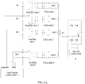
- the frequency gating battery active equalization apparatus includes a controlled alternating current power supply 101, an alternating current electric energy allocation unit 102, a filter unit 103 (such as a filter 1 to a filter N, where N is a positive integer greater than 1), a rectifier unit 104 (Rectifier unit, Rec for short) (such as Reel to RecN), and an equalization control unit 105.
- the alternating current electric energy allocation unit 102 includes at least one input port In1 and N output ports, and the N output ports are numbered Out1 to OutN.
- the frequency gating battery active equalization apparatus determines a frequency interval of a filter unit 103 corresponding to a battery unit that needs to be supplemented with energy.
- the frequency instruction signal falls within a frequency interval corresponding to a conductive path on which the battery that needs to be supplemented with energy is located. In addition, the frequency instruction signal does not fall within a frequency interval corresponding to a conductive path on which any another battery that does not need to be supplemented with energy is located.
- the frequency gating battery pack active equalization apparatus determines the to-be-equalized battery unit in the battery pack by detecting energy statuses of all battery units in the battery pack, or the frequency gating battery pack active equalization apparatus obtains the to-be-equalized battery unit in the battery pack from a terminal.
- the to-be-equalized battery unit is configured to indicate a battery unit that needs to be supplemented with energy.
- the to-be-equalized battery unit may be one battery unit, or may be multiple battery units. This is not specifically limited herein.
- the frequency gating battery pack active equalization apparatus determines the to-be-equalized battery unit by detecting a status parameter of each battery unit.
- the status parameter may be a voltage, may be a current, or may be an SOC obtained by means of calculation by the frequency gating battery pack active equalization apparatus. This is not specifically limited herein.
- the frequency gating battery pack active equalization apparatus obtains the current actual equalization current value of the to-be-equalized battery unit by detecting a current of the to-be-equalized battery unit.
- detecting the current actual equalization current value of the to-be-equalized battery unit such as using a hall current sensor or performing resistance sampling.
- a sensor detects the current of the to-be-equalized battery unit, so as to obtain the current actual equalization current value of the to-be-equalized battery unit, and sends the current actual equalization current value of the to-be-equalized battery unit to the frequency gating battery pack active equalization apparatus; or the sensor detects the current of the to-be-equalized battery unit, so as to obtain the current actual equalization current value of the to-be-equalized battery unit, and sends the current actual equalization current value of the to-be-equalized battery unit to another battery unit other than the to-be-equalized battery unit, and the another battery unit sends the current actual equalization current value of the to-be-equalized battery unit to the frequency gating battery pack active equalization apparatus.
- the frequency gating battery pack active equalization apparatus obtains, by means of calculation, the current actual equalization current value of the to-be-equalized battery unit by obtaining a related parameter of the to-be-equalized battery unit, and so on. This is not specifically limited herein.
- the target equalization current value is an equalization current value determined by the frequency gating battery pack active equalization apparatus according to a current energy status of the to-be-equalized battery unit.
- the target circuit is a circuit that includes a circuit component connected to the to-be-equalized battery unit, the alternating current power supply, and the to-be-equalized battery unit.
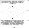
- step 203 When it is determined that the difference between the current actual equalization current value of the to-be-equalized battery unit and the target equalization current value falls within the range of the preset threshold, the following step 203 does not need to be performed, and the current actual equalization current value of the to-be-equalized battery unit is kept unchanged.
- Step 203 When it is determined that the difference between the current actual equalization current value of the to-be-equalized battery unit and the target equalization current value does not fall within the range of the preset threshold, adjust a fundamental amplitude of an alternating current power supply of a target circuit on which the to-be-equalized battery unit is located and/or a voltage gain of the target circuit, so that the difference between the current actual equalization current value of the to-be-equalized battery unit and the target equalization current value falls within the range of the preset threshold.
- the target circuit is a conducting circuit on which the to-be-equalized battery unit is located.
- the fundamental amplitude of the alternating current power supply of the target circuit and/or the voltage gain of the target circuit are/is adjusted, so as to indirectly achieve a purpose of adjusting the current actual equalization current value of the to-be-equalized battery unit.
- the fundamental amplitude of the alternating current power supply and/or the voltage gain of the target circuit may be adjusted for multiple times, until the difference between the current actual equalization current value of the to-be-equalized battery unit and the target equalization current value falls within the range of the preset threshold, so as to achieve a purpose of energy equalization of each battery unit.
- the frequency gating battery active equalization apparatus includes a controlled alternating current power supply, an alternating current electric energy allocation unit, a filter unit (such as a filter unit 1 to a filter unit N, where N is a positive integer greater than 1), a rectifier unit (such as a rectifier unit 1 to a rectifier unit N), and an equalization control unit C1.
- a filter unit such as a filter unit 1 to a filter unit N, where N is a positive integer greater than 1
- a rectifier unit such as a rectifier unit 1 to a rectifier unit N
- an equalization control unit C1 an equalization control unit
- a voltage output port of the controlled alternating current power supply is connected to an input port In1 of the alternating current electric energy allocation unit.
- the alternating current electric energy allocation unit is implemented by using a multi-winding coupling transformer structure.
- An input winding In1 and output windings Out1 to OutN are wound around one magnetic core in a magnetic coupling manner.
- Out1 to OutN are one-to-one corresponding to the filter units, and are connected to input sides of corresponding filter units.
- the filter units are implemented by using a series-parallel network of inductor and capacitor elements.
- An output side of the filter unit is connected to an alternating current side of the rectifier unit.
- the rectifier unit is implemented by using a full-bridge rectifier that includes a diode.
- An output side of the rectifier unit is connected to a battery unit.
- the equalization control unit is connected to the battery unit.
- the equalization control unit is also connected to the controlled alternating current power supply.
- FIG. 3-b shows a target circuit corresponding to the to-be-equalized battery unit.
- a circuit between an alternating current power supply V AC and a battery unit V B constructs a two-port network. Therefore, a current I B flowing into the battery unit V B is related to a fundamental amplitude of the power supply V AC and a voltage gain of the two-port network.
- the fundamental amplitude of the power supply V AC and/or the voltage gain of the two-port network are/is adjusted, so that the current I B of the battery unit V B meets a preset condition, so as to achieve a purpose of energy equalization of each battery unit.
- a to-be-equalized battery unit in a battery pack is determined, and a current actual equalization current value of the to-be-equalized battery unit is obtained; and when it is determined that a difference between the current actual equalization current value of the to-be-equalized battery unit and a target equalization current value does not fall within a range of a preset threshold, a fundamental amplitude of an alternating current power supply of a target circuit on which the to-be-equalized battery unit is located and/or a voltage gain of the target circuit are/is adjusted, so that the difference between the current actual equalization current value of the to-be-equalized battery unit and the target equalization current value falls within the range of the preset threshold. It may be learned that an equalization current is adjusted without a limit of an adjustment range by adjusting the amplitude of the alternating current power supply and/or the voltage gain, so that the equalization current may be adjusted in a wide range with high flexibility.
- a frequency gating battery pack active equalization apparatus obtains, by means of calculation, the current actual equalization current value of the to-be-equalized battery unit according to the fundamental amplitude of the alternating current power supply of the target circuit and the voltage gain of the target circuit. Different operating currents corresponding to series battery units may be obtained.
- An equalization current obtained by means of calculation has high accuracy, and therefore this helps improve SOC calculation accuracy of a battery pack and of a battery unit.
- the obtaining a fundamental amplitude of an alternating current power supply of a target circuit and a voltage gain of the target circuit includes:
- a current of the to-be-equalized battery unit is detected by using a sensor, so as to obtain the current actual equalization current value of the to-be-equalized battery unit.
- the current actual equalization current value of the to-be-equalized battery unit may be obtained from a terminal by the frequency gating battery active equalization apparatus, and so on. This is not specifically limited herein.
- Step 404 Determine whether a difference between the current actual equalization current value of the to-be-equalized battery unit and a target equalization current value falls within a range of a preset threshold. If the difference between the current actual equalization current value of the to-be-equalized battery unit and the target equalization current value does not fall within the range of the preset threshold, perform step 405.
- the target equalization current value is an equalization current value obtained from a sensor by the frequency gating battery pack active equalization apparatus or an equalization current value defined by a user.
- a sensor detects energy statuses of all battery units, so as to determine the target equalization current value, and sends the target equalization current value to the frequency gating battery pack active equalization apparatus.
- a user defines a target equalization current value on the frequency gating battery pack active equalization apparatus, and the frequency gating battery pack active equalization apparatus receives the target equalization current value defined by the user.
- the preset threshold is a threshold defined by a user or a default threshold of the frequency gating battery pack active equalization apparatus.
- step 405 When the difference between the current actual equalization current value of the to-be-equalized battery unit and the target equalization current value does not fall within the range of the preset threshold, the following step 405 does not need to be performed, and the current actual equalization current value of the to-be-equalized battery unit is kept unchanged.
- the current actual equalization current value of the to-be-equalized battery unit in addition to the manner of determining whether the difference between the current actual equalization current value of the to-be-equalized battery unit and the target equalization current value falls within the range of the preset threshold, it may be determined whether the current actual equalization current value of the to-be-equalized battery unit is equal to the target equalization current value. If the current actual equalization current value of the to-be-equalized battery unit is not equal to the target equalization current value, the fundamental amplitude of the alternating current power supply of the target circuit on which the to-be-equalized battery unit is located and/or the voltage gain of the target circuit are/is adjusted, so that the current actual equalization current value of the to-be-equalized battery unit is equal to the target equalization current value. Certainly, another determining manner may also be selected. This is not specifically limited herein.
- the threshold may be set in another manner. This is not specifically limited herein.
- the fundamental amplitude of the alternating current power supply and/or the voltage gain of the target circuit are/is adjusted, so as to achieve a purpose of energy equalization of each battery unit.
- the method before the adjusting the fundamental amplitude of the alternating current power supply of the target circuit on which the to-be-equalized battery unit is located and/or the voltage gain of the target circuit, the method further includes: when the target equalization current value of the to-be-equalized battery unit is determined, obtaining the fundamental amplitude of the alternating current power supply of the target circuit and/or the voltage gain of the target circuit.
- the fundamental amplitude of the alternating current power supply of the target circuit and/or the voltage gain of the target circuit may be obtained by means of external detection by the frequency gating battery pack active equalization apparatus, may be obtained by means of internal reading by the frequency gating battery pack active equalization apparatus, or may be obtained in a user input manner. This is not specifically limited herein.
- an instruction signal of the target parameter is generated according to the fundamental amplitude of the alternating current power supply of the target circuit and/or a voltage gain value of the target circuit.
- a control unit in the frequency gating battery pack active equalization apparatus may generate an initial instruction signal of the fundamental amplitude of the alternating current power supply of the target circuit and/or the voltage gain of the target circuit according to the fundamental amplitude of the alternating current power supply of the target circuit and/or the voltage gain of the target circuit.
- the instruction signal of the fundamental amplitude of the alternating current power supply of the target circuit and/or the voltage gain of the target circuit is output to a control unit corresponding to the instruction signal of the fundamental amplitude of the alternating current power supply of the target circuit and/or the voltage gain of the target circuit.
- the instruction signal of the fundamental amplitude of the alternating current power supply of the target circuit and/or the voltage gain of the target circuit is output to the control unit corresponding to the initial instruction signal of the fundamental amplitude of the alternating current power supply of the target circuit and/or the voltage gain of the target circuit.
- the initial signal is used as a reference for subsequently adjusting the fundamental amplitude of the alternating current power supply and/or the voltage gain of the target circuit, so as to avoid an extremely heavy workload caused in a subsequent adjustment process due to an extremely large or small adjustment.
- the fundamental amplitude of the alternating current power supply and/or the voltage gain of the target circuit are/is adjusted, so that the difference between the current actual equalization current value of the to-be-equalized battery unit and the target equalization current value falls within the range of the preset threshold.
- An adjustment range is not limited, so that an equalization current may be adjusted in a wide range with high flexibility.
- a fundamental amplitude of the alternating current power supply V AC is related to a voltage amplitude of a direct current power supply DC1 and a driver phase shift angle of a full-bridge inverter unit. Therefore, the fundamental amplitude of the alternating current power supply V AC may be indirectly adjusted by controlling the voltage amplitude of the direct current power supply DC1 or controlling the driver phase shift angle of the full-bridge inverter structure, so as to finally achieve a purpose of adjusting a magnitude of an equalization current I B .
- a voltage gain of a two-port network is related to a driving frequency of an alternating current voltage on an input side. Therefore, the voltage gain of the two-port network may be adjusted by controlling a driving frequency of the full-bridge inverter structure, so as to finally achieve the purpose of adjusting the magnitude of the equalization current I B .
- the purpose of adjusting the equalization current I B may be achieved in any one of the three manners: adjusting the voltage amplitude of the direct current power supply DC1, adjusting the driving frequency of the full-bridge inverter structure, or adjusting the driver phase shift angle of the full-bridge inverter structure, thereby having high flexibility.
- the alternating current power supply V AC may be implemented in many manners.
- a corresponding equalization current adjustment method used when the alternating current power supply V AC is implemented by using the full-bridge inverter structure is selected in this embodiment of the present invention.
- a corresponding principle may be generalized to any implementation of the alternating current power supply V AC , such as an implementation using a half-bridge inverter structure, a power amplifier structure, or a half-bridge three-level inverter structure. This is not specifically limited herein.
- the adjusting the fundamental amplitude of the alternating current power supply, so that the difference between the current actual equalization current value of the to-be-equalized battery unit and the target equalization current value falls within the range of the preset threshold includes:
- the purpose of adjusting the equalization current may still be achieved by adjusting the driver phase shift angle and/or the voltage amplitude of the direct current power supply, so that the equalization current may be adjusted in a wide range with high flexibility.
- the adjusting the voltage gain of the target circuit so that the difference between the current actual equalization current value of the to-be-equalized battery unit and the target equalization current value falls within the range of the preset threshold includes:
- the purpose of adjusting the equalization current may still be achieved by adjusting the driving frequency, so that the equalization current may be adjusted in a wide range with high flexibility.
- the adjusting the fundamental amplitude of the alternating current power supply and the voltage gain of the target circuit, so that the difference between the current actual equalization current value of the to-be-equalized battery unit and the target equalization current value falls within the range of the preset threshold includes:
- the purpose of adjusting the equalization current may still be achieved by using the driving frequency and at least one sub-target parameter in the driver phase shift angle and the voltage amplitude of the direct current power supply, so that the equalization current may be adjusted in a wide range with high flexibility.
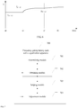
- a specific adjustment process is as follows: f 1 and f 2 are respectively two driving frequencies that are on an equalization current curve and that are corresponding to I set intersection points.
- I set is a preset target equalization current value of a to-be-equalized battery unit.
- I real is an actual equalization current value of the to-be-equalized battery unit.
- f center is a center frequency of a target circuit currently corresponding to the to-be-equalized battery unit.
- the driving frequencies and the center frequency meet the following relationship: f 2 >f center >f 1 .
- T s is a current driving cycle of the full-bridge inverter structure.
- I set is a target equalization current value obtained by an apparatus by calculating currents or voltages of all battery units in a battery pack in advance.
- f s is controlled and decreased by using an equalization control unit, so that a value of I real increases, and a value of
- f s is controlled and increased by using an equalization control unit, so that a value of I real decreases, and a value of
- f center >f 1 >f s , such as at a point 4 in the figure
- f s is controlled and increased by using an equalization control unit, so that a value of I real increases, and a value of
- the driving frequency of the full-bridge inverter structure is adjusted for at least one time, until the actual equalization current value of the to-be-equalized battery unit reaches the preset target equalization current value, so as to implement current equalization of battery units in an entire battery pack.
- ⁇ set is a phase shift angle that is on an equalization current curve and that is corresponding to an I set intersection point.
- I set is a preset target equalization current value of a to-be-equalized battery unit.
- ⁇ s is a current driver phase shift angle of a full-bridge inverter structure (such as a current driver phase shift angle of the full-bridge inverter structure in a case of S1, S2, S3, or S4).
- ⁇ s is controlled and decreased by using an equalization control unit, so that a value of I real increases, and a value of
- ⁇ s is controlled and increased by using an equalization control unit, so that a value of I real decreases, and a value of
- the driver phase shift angle of the full-bridge inverter structure is adjusted for at least one time, until the actual equalization current value of the to-be-equalized battery unit reaches the preset target equalization current value, so as to implement current equalization of battery units in an entire battery pack.
- V set is a voltage value that is on an equalization current curve and that is corresponding to an I set intersection point.
- I set is a preset target equalization current value of a to-be-equalized battery unit.
- V dc is a current voltage amplitude of a direct current power supply.
- V dc V set , such as at a point 1 in the figure
- V dc is controlled and decreased by using an equalization control unit, so that a value of I real decreases, and a value of
- V dc When V dc ⁇ V set , such as at a point 2 in the figure, V dc is controlled and increased by using an equalization control unit, so that a value of I real increases, and a value of
- the voltage amplitude of the direct current power supply is adjusted for at least one time, until the actual equalization current value of the to-be-equalized battery unit reaches the preset target equalization current value, so as to implement current equalization of battery units in an entire battery pack.
- x is all fixed parameters of a conductive path corresponding to each battery unit. Fixed parameters x of conductive paths corresponding to different battery units are not exactly the same. In addition, x remains unchanged after a frequency gating battery pack active equalization apparatus is determined, but y is a variable parameter in the frequency gating battery pack active equalization apparatus. After the frequency gating battery pack active equalization apparatus is determined, an equalization control unit may directly or indirectly modify all or some parameters in y.
- the fundamental amplitude of the alternating current power supply V AC is related to the voltage amplitude of the direct current power supply DC1 and the driver phase shift angle of the full-bridge inverter unit.
- C p is first capacitance
- C s is second capacitance
- L p is first inductance
- L s is second inductance.
- C p , L p , C s , and L s are respectively fixed parameters used in a process of calculating an equalization current. All of the driving frequency f s of the alternating current power supply V AC , the driver phase shift angle PF of the full-bridge inverter structure, and the voltage amplitude of the direct current power supply V dc are variable parameters.
- a specific mathematical form of the formula (1) is that a current I B of a battery unit V B approximately meets the following relationship within an engineering-allowed range:
- the target equalization current value of the to-be-equalized battery unit is obtained by means of calculation according to the driver phase shift angle, the voltage amplitude of the direct current power supply, and the driving frequency.
- the frequency gating battery pack active equalization apparatus is used for active equalization of a battery pack that includes four series battery units.
- a control unit starts energy equalization for a battery unit B2 at a t0 moment.
- An initially specified voltage amplitude of a direct current power supply is output to a direct current control unit, and a driver phase shift angle and a driving frequency are output to a full-bridge inverter control unit, so as to obtain, by means of calculation, a current actual equalization current I B2_initi corresponding to B2 at the moment.
- an equalization control unit when receiving an equalization current instruction I B2_set corresponding to B2, obtains, by means of calculation, one of the following that meets the equalization current instruction: a corresponding voltage amplitude of the direct current power supply, a corresponding driving frequency of an alternating current power supply, or a corresponding driver phase shift angle of an alternating current power supply, outputs the corresponding voltage amplitude of the direct current power supply at the moment to the direct current control unit, and outputs the driver phase shift angle and the driving frequency to the full-bridge inverter control unit.
- the equalization control unit adjusts one or more parameters in three parameters: the voltage amplitude of the direct current power supply, the driver phase shift angle, and the driving frequency, until the actual equalization current I B2_real of B2 reaches the current instruction I B2_set at a t3 moment.
- the following further provides a related apparatus used to cooperate with the foregoing method.
- an embodiment of the present invention provides a frequency gating battery pack active equalization apparatus, including: a determining module 701, an obtaining module 702, a judging module 703, and an adjustment module 704.
- the determining module 701 is configured to determine a to-be-equalized battery unit in a battery pack.
- the obtaining module 702 is configured to obtain a current actual equalization current value of the to-be-equalized battery unit determined by the determining module 701.
- the judging module 703 is configured to determine whether a difference between the current actual equalization current value that is of the to-be-equalized battery unit and that is obtained by the obtaining module 702 and a target equalization current value falls within a range of a preset threshold.
- the preset threshold is a threshold defined by a user or a default threshold of the frequency gating battery pack active equalization apparatus.
- the target equalization current value is an equalization current value obtained from a sensor by the frequency gating battery pack active equalization apparatus or an equalization current value defined by a user.
- the adjustment module 704 is configured to: when the judging module 703 determines that the difference between the current actual equalization current value of the to-be-equalized battery unit and the target equalization current value does not fall within the range of the preset threshold, adjust a fundamental amplitude of an alternating current power supply of a target circuit on which the to-be-equalized battery unit is located and/or a voltage gain of the target circuit, so that the difference between the current actual equalization current value of the to-be-equalized battery unit and the target equalization current value falls within the range of the preset threshold, where the target equalization current value is an equalization current value determined by the frequency gating battery pack active equalization apparatus according to a current energy status of the to-be-equalized battery unit, and the target circuit is a circuit that includes a circuit component connected to the to-be-equalized battery unit, the alternating current power supply, and the to-be-equalized battery unit.
- a determining module determines a to-be-equalized battery unit in a battery pack; an obtaining module obtains a current actual equalization current value of the to-be-equalized battery unit; and when the judging module determines that a difference between the current actual equalization current value of the to-be-equalized battery unit and a target equalization current value does not fall within a range of a preset threshold, an adjustment module adjusts a fundamental amplitude of an alternating current power supply of a target circuit on which the to-be-equalized battery unit is located and/or a voltage gain of the target circuit, so that the difference between the current actual equalization current value of the to-be-equalized battery unit and the target equalization current value falls within the range of the preset threshold. It may be learned that an equalization current is adjusted by adjusting the amplitude of the alternating current power supply and/or the voltage gain, so that the equalization current may be adjusted in a wide range with high flexibility.
- the obtaining module 702 is specifically configured to: obtain the fundamental amplitude of the alternating current power supply of the target circuit and the voltage gain of the target circuit, and obtain, by means of calculation, the current actual equalization current value of the to-be-equalized battery unit according to the fundamental amplitude of the alternating current power supply of the target circuit and the voltage gain of the target circuit.
- the obtaining module 702 is specifically configured to detect a current of the to-be-equalized battery unit by using a sensor, so as to obtain the current actual equalization current value of the to-be-equalized battery unit.
- the current actual equalization current value of the to-be-equalized battery unit may be obtained from a terminal by the frequency gating battery active equalization apparatus, and so on. This is not specifically limited herein.
- the obtaining module 702 is specifically configured to: obtain a driver phase shift angle and a voltage amplitude of a direct current power supply that are related to the fundamental amplitude of the alternating current power supply of the target circuit, where the driver phase shift angle is a driver phase shift angle of a switch structure in the alternating current power supply, and the alternating current power supply is formed according to the direct current power supply and the switch structure in the alternating current power supply; obtain a driving frequency related to the voltage gain of the target circuit, where the driving frequency is a driving frequency of the switch structure in the alternating current power supply; and obtain, by means of calculation, the current actual equalization current value of the to-be-equalized battery unit according to the driver phase shift angle, the voltage amplitude of the direct current power supply, and the driving frequency that are obtained by the obtaining module.
- the adjustment module 704 is specifically configured to: generate, according to the driver phase shift angle, a first instruction signal used to control the driver phase shift angle and/or generate, according to the voltage amplitude of the direct current power supply, a first instruction signal used to control the voltage amplitude of the direct current power supply; and output at least one first instruction signal in the first instruction signal used to control the driver phase shift angle and the first instruction signal used to control the voltage amplitude of the direct current power supply to a control unit corresponding to the first instruction signal, so as to adjust the fundamental amplitude of the alternating current power supply, so that the difference between the current actual equalization current value of the to-be-equalized battery unit and the target equalization current value falls within the range of the preset threshold.
- a purpose of adjusting the equalization current may still be achieved by adjusting the driver phase shift angle and/or the voltage amplitude of the direct current power supply, so that the equalization current may be adjusted in a wide range with high flexibility.
- the adjustment module 704 is specifically configured to: generate, according to the driving frequency, a second instruction signal used to control the driving frequency, and output the second instruction signal used to control the driving frequency to a control unit corresponding to the second instruction signal, so as to adjust the voltage gain of the target circuit, so that the difference between the current actual equalization current value of the to-be-equalized battery unit and the target equalization current value falls within the range of the preset threshold.
- the purpose of adjusting the equalization current may still be achieved by adjusting the driving frequency, so that the equalization current may be adjusted in a wide range with high flexibility.
- the adjustment module 704 is specifically configured to: generate, according to the driver phase shift angle, a first instruction signal used to control the driver phase shift angle and/or generate, according to the voltage amplitude of the direct current power supply, a first instruction signal used to control the voltage amplitude of the direct current power supply; generate, according to the driving frequency, a second instruction signal used to control the driving frequency; output at least one first instruction signal in the first instruction signal used to control the driver phase shift angle and the first instruction signal used to control the voltage amplitude of the direct current power supply to a control unit corresponding to the first instruction signal; and output the second instruction signal used to control the driving frequency to a control unit corresponding to the second instruction signal, so as to adjust the fundamental amplitude of the alternating current power supply and the voltage gain of the target circuit, so that the difference between the current actual equalization current value of the to-be-equalized battery unit and the target equalization current value falls within the range of the preset threshold.
- the purpose of adjusting the equalization current may still be achieved by using the driving frequency and at least one sub-target parameter in the driver phase shift angle and the voltage amplitude of the direct current power supply, so that the equalization current may be adjusted in a wide range with high flexibility.
- the adjustment module adjusts at least one parameter in the three parameters: the driver phase shift angle, the voltage amplitude of the direct current power supply, and the driving frequency, so that the difference between the current actual equalization current value of the to-be-equalized battery unit and the target equalization current value falls within the range of the preset threshold.
- An adjustment range is not limited, so that the equalization current may be adjusted in a wide range with high flexibility.
- a frequency gating battery pack active equalization apparatus including: a controlled alternating current power supply 101, an alternating current electric energy allocation unit 102, a filter unit 103, a rectifier unit 104, and an equalization control unit 105.
- the controlled alternating current power supply 101 is connected to the alternating current electric energy allocation unit 102, the alternating current electric energy allocation unit 102 is connected to the filter unit 103, the filter unit 103 is connected to the rectifier unit 104, the rectifier unit 104 is connected to a battery unit (such as B1, B2, B3, ..., or BN in FIG. 1 ) in a battery pack 106, the battery unit 106 is connected to the equalization control unit 105, and the equalization control unit 105 is connected to the controlled alternating current power supply 101.
- a battery unit such as B1, B2, B3, ..., or BN in FIG. 1
- the equalization control unit 105 is configured to: determine a to-be-equalized battery unit in the battery pack, and obtain a current actual equalization current value of the to-be-equalized battery unit.
- the equalization control unit 105 is further configured to: when determining that a difference between the current actual equalization current value of the to-be-equalized battery unit and a target equalization current value does not fall within a range of a preset threshold, adjust a fundamental amplitude of an alternating current power supply of a target circuit on which the to-be-equalized battery unit is located and/or a voltage gain of the target circuit, so that the difference between the current actual equalization current value of the to-be-equalized battery unit and the target equalization current value falls within the range of the preset threshold, where the target equalization current value is an equalization current value determined by the frequency gating battery pack active equalization apparatus according to a current energy status of the to-be-equalized battery unit, and the target circuit is a circuit that includes a circuit component connected to the to-be-equalized battery unit, the alternating current power supply, and the to-be-equalized battery unit.
- the equalization control unit determines the to-be-equalized battery unit in the battery pack by detecting energy statuses of all battery units in the battery pack, or the equalization control unit obtains the to-be-equalized battery unit in the battery pack from a terminal.
- the to-be-equalized battery unit is configured to indicate a battery unit that needs to be supplemented with energy.
- the to-be-equalized battery unit may be one battery unit, or may be multiple battery units. This is not specifically limited herein.
- the target equalization current value is an equalization current value obtained from a sensor by the frequency gating battery pack active equalization apparatus or an equalization current value defined by a user.
- a sensor detects energy statuses of all battery units, so as to determine the target equalization current value, and sends the target equalization current value to the frequency gating battery pack active equalization apparatus.
- a user defines a target equalization current value on the frequency gating battery pack active equalization apparatus, and the frequency gating battery pack active equalization apparatus receives the target equalization current value defined by the user.
- the preset threshold is a threshold defined by a user or a default threshold of the frequency gating battery pack active equalization apparatus.
- the equalization control unit determines the to-be-equalized battery unit by detecting a status parameter of each battery unit.
- the status parameter may be a voltage, may be a current, or may be an SOC obtained by means of calculation by the frequency gating battery pack active equalization apparatus. This is not specifically limited herein.
- the equalization control unit 105 is specifically configured to: obtain the fundamental amplitude of the alternating current power supply of the target circuit and the voltage gain of the target circuit, and obtain, by means of calculation, the current actual equalization current value of the to-be-equalized battery unit according to the fundamental amplitude of the alternating current power supply of the target circuit and the voltage gain of the target circuit.
- the equalization control unit 105 is specifically configured to detect a current of the to-be-equalized battery unit by using a sensor, so as to obtain the current actual equalization current value of the to-be-equalized battery unit.
- the current actual equalization current value of the to-be-equalized battery unit may be obtained from another terminal by the equalization control unit, and so on. This is not specifically limited herein.
- the equalization control unit 105 is specifically configured to: obtain a driver phase shift angle and a voltage amplitude of a direct current power supply that are related to the fundamental amplitude of the alternating current power supply of the target circuit, where the driver phase shift angle is a driver phase shift angle of a switch structure in the alternating current power supply, and the alternating current power supply is formed according to the direct current power supply and the switch structure in the alternating current power supply; and obtain a driving frequency related to the voltage gain of the target circuit, where the driving frequency is a driving frequency of the switch structure in the alternating current power supply; and the equalization control unit is specifically configured to: obtain, by means of calculation, the current actual equalization current value of the to-be-equalized battery unit according to the driver phase shift angle, the voltage amplitude of the direct current power supply, and the driving frequency.
- the equalization control unit 105 is specifically configured to: generate, according to the driver phase shift angle, a first instruction signal used to control the driver phase shift angle and/or generate, according to the voltage amplitude of the direct current power supply, a first instruction signal used to control the voltage amplitude of the direct current power supply; and output at least one first instruction signal in the first instruction signal used to control the driver phase shift angle and the first instruction signal used to control the voltage amplitude of the direct current power supply to a control unit corresponding to the first instruction signal, so as to adjust the fundamental amplitude of the alternating current power supply, so that the difference between the current actual equalization current value of the to-be-equalized battery unit and the target equalization current value falls within the range of the preset threshold.
- a purpose of adjusting the equalization current may still be achieved by adjusting the driver phase shift angle and/or the voltage amplitude of the direct current power supply, so that the equalization current may be adjusted in a wide range with high flexibility.
- the equalization control unit 105 is specifically configured to output the second instruction signal used to control the driving frequency to a control unit corresponding to the second instruction signal, so as to adjust the voltage gain of the target circuit, so that the difference between the current actual equalization current value of the to-be-equalized battery unit and the target equalization current value falls within the range of the preset threshold.
- the purpose of adjusting the equalization current may still be achieved by adjusting the driving frequency, so that the equalization current may be adjusted in a wide range with high flexibility.
- the equalization control unit 105 is specifically configured to: generate, according to the driver phase shift angle, a first instruction signal used to control the driver phase shift angle and/or generate, according to the voltage amplitude of the direct current power supply, a first instruction signal used to control the voltage amplitude of the direct current power supply; generate, according to the driving frequency, a second instruction signal used to control the driving frequency; output at least one first instruction signal in the first instruction signal used to control the driver phase shift angle and the first instruction signal used to control the voltage amplitude of the direct current power supply to a control unit corresponding to the first instruction signal; and output the second instruction signal used to control the driving frequency to a control unit corresponding to the second instruction signal, so as to adjust the fundamental amplitude of the alternating current power supply and the voltage gain of the target circuit, so that the difference between the current actual equalization current value of the to-be-equalized battery unit and the target equalization current value falls within the range of the preset threshold.
- the purpose of adjusting the equalization current may still be achieved by using the driving frequency and at least one sub-target parameter in the driver phase shift angle and the voltage amplitude of the direct current power supply, so that the equalization current may be adjusted in a wide range with high flexibility.
- a to-be-equalized battery unit in a battery pack is determined, and a current actual equalization current value of the to-be-equalized battery unit is obtained; and when it is determined that a difference between the current actual equalization current value of the to-be-equalized battery unit and a target equalization current value does not fall within a range of a preset threshold, a fundamental amplitude of an alternating current power supply of a target circuit on which the to-be-equalized battery unit is located and/or a voltage gain of the target circuit are/is adjusted, so that the difference between the current actual equalization current value of the to-be-equalized battery unit and the target equalization current value falls within the range of the preset threshold. It may be learned that an equalization current is adjusted without a limit of an adjustment range by adjusting the amplitude of the alternating current power supply and/or the voltage gain, so that the equalization current may be adjusted in a wide range with high flexibility.
- the disclosed system, apparatus, and method may be implemented in other manners.
- the described apparatus embodiment is merely an example.
- the unit division is merely logical function division and may be other division in actual implementation.
- a plurality of units or components may be combined or integrated into another system, or some features may be ignored or not performed.
- the displayed or discussed mutual couplings or direct couplings or communication connections may be implemented through some interfaces, indirect couplings or communication connections between the apparatuses or units, or electrical connections, mechanical connections, or connections in other forms.
- the units described as separate parts may or may not be physically separate, and parts displayed as units may or may not be physical units, may be located in one position, or may be distributed on a plurality of network units. Some or all of the units may be selected according to actual needs to achieve the objectives of the solutions of the embodiments.
- function units in the embodiments of the present invention may be integrated into one processing unit, or each of the units may exist alone physically, or two or more units are integrated into one unit.
- the integrated unit may be implemented in a form of hardware, or may be implemented in a form of a software function unit.
- the integrated unit When the integrated unit is implemented in the form of a software function unit and sold or used as an independent product, the integrated unit may be stored in a computer-readable storage medium. Based on such an understanding, the technical solutions of the present invention essentially, or the part contributing to the prior art, or all or some of the technical solutions may be implemented in the form of a software product.
- the software product is stored in a storage medium and includes several instructions for instructing a computer device (which may be a personal computer, a server, or a network device) to perform all or some of the steps of the methods described in the embodiments of the present invention.
- the foregoing storage medium includes: any medium that can store program code, such as a USB flash drive, a removable hard disk, a read-only memory (ROM, Read-Only Memory), a random access memory (RAM, Random Access Memory), a magnetic disk, or an optical disc.
- program code such as a USB flash drive, a removable hard disk, a read-only memory (ROM, Read-Only Memory), a random access memory (RAM, Random Access Memory), a magnetic disk, or an optical disc.
Landscapes
- Engineering & Computer Science (AREA)
- Power Engineering (AREA)
- Secondary Cells (AREA)
- Charge And Discharge Circuits For Batteries Or The Like (AREA)
Priority Applications (1)
| Application Number | Priority Date | Filing Date | Title |
|---|---|---|---|
| EP22152452.3A EP4054050B1 (de) | 2015-10-09 | 2016-04-15 | Ausgleichsstromeinstellverfahren und zugehörige vorrichtung |
Applications Claiming Priority (2)
| Application Number | Priority Date | Filing Date | Title |
|---|---|---|---|
| CN201510648284.XA CN106571649B (zh) | 2015-10-09 | 2015-10-09 | 一种均衡电流调节方法及相关装置 |
| PCT/CN2016/079421 WO2017059668A1 (zh) | 2015-10-09 | 2016-04-15 | 一种均衡电流调节方法及相关装置 |
Related Child Applications (1)
| Application Number | Title | Priority Date | Filing Date |
|---|---|---|---|
| EP22152452.3A Division EP4054050B1 (de) | 2015-10-09 | 2016-04-15 | Ausgleichsstromeinstellverfahren und zugehörige vorrichtung |
Publications (2)
| Publication Number | Publication Date |
|---|---|
| EP3346573A1 true EP3346573A1 (de) | 2018-07-11 |
| EP3346573A4 EP3346573A4 (de) | 2018-09-05 |
Family
ID=58487438
Family Applications (2)
| Application Number | Title | Priority Date | Filing Date |
|---|---|---|---|
| EP22152452.3A Active EP4054050B1 (de) | 2015-10-09 | 2016-04-15 | Ausgleichsstromeinstellverfahren und zugehörige vorrichtung |
| EP16852978.2A Ceased EP3346573A4 (de) | 2015-10-09 | 2016-04-15 | Ausgleichsstromeinstellverfahren und zugehörige vorrichtung |
Family Applications Before (1)
| Application Number | Title | Priority Date | Filing Date |
|---|---|---|---|
| EP22152452.3A Active EP4054050B1 (de) | 2015-10-09 | 2016-04-15 | Ausgleichsstromeinstellverfahren und zugehörige vorrichtung |
Country Status (4)
| Country | Link |
|---|---|
| US (1) | US10581254B2 (de) |
| EP (2) | EP4054050B1 (de) |
| CN (1) | CN106571649B (de) |
| WO (1) | WO2017059668A1 (de) |
Families Citing this family (12)
| Publication number | Priority date | Publication date | Assignee | Title |
|---|---|---|---|---|
| CN107436560A (zh) * | 2016-05-26 | 2017-12-05 | 台达电子企业管理(上海)有限公司 | 电源控制方法、电源控制装置和电源控制系统 |
| CN107785943B (zh) * | 2016-08-26 | 2020-02-21 | 华为技术有限公司 | 一种均衡电池组能量的装置及系统 |
| CN108011425B (zh) * | 2017-12-25 | 2021-04-16 | 上海电气集团股份有限公司 | 一种电池组主动均衡电路及方法 |
| CN109216804B (zh) * | 2018-09-25 | 2021-01-08 | 南京理工大学 | 一种串联电池模块的双向均衡电路及均衡方法 |
| KR102347920B1 (ko) * | 2018-10-12 | 2022-01-05 | 주식회사 엘지에너지솔루션 | 배터리 관리 장치 및 방법 |
| CN110231576A (zh) * | 2019-06-14 | 2019-09-13 | 安徽锐能科技有限公司 | 一种基于电池补电式主动均衡的soe估计方法 |
| CN110231577A (zh) * | 2019-06-14 | 2019-09-13 | 安徽锐能科技有限公司 | 一种基于电池补电式主动均衡的soe估计装置 |
| CN110266225B (zh) * | 2019-06-28 | 2024-01-09 | 武汉新能源研究院有限公司 | 控制发电装置的发电电流的方法及系统 |
| US11545841B2 (en) * | 2019-11-18 | 2023-01-03 | Semiconductor Components Industries, Llc | Methods and apparatus for autonomous balancing and communication in a battery system |
| CN115113090B (zh) * | 2022-06-20 | 2025-08-01 | 东莞市长工微电子有限公司 | 一种故障确定方法及计算机可读存储介质 |
| CN116054343A (zh) * | 2023-02-13 | 2023-05-02 | 杭州协能科技股份有限公司 | 电池模组的主动均衡电路及其控制方法 |
| JP2025152979A (ja) * | 2024-03-29 | 2025-10-10 | 株式会社Gsユアサ | 電力変換器、電力変換器の制御方法、充電装置及び車両 |
Family Cites Families (20)
| Publication number | Priority date | Publication date | Assignee | Title |
|---|---|---|---|---|
| US5631534A (en) | 1995-08-21 | 1997-05-20 | Delco Electronics Corp. | Bidirectional current pump for battery charge balancing |
| US5659237A (en) * | 1995-09-28 | 1997-08-19 | Wisconsin Alumni Research Foundation | Battery charging using a transformer with a single primary winding and plural secondary windings |
| FR2927200B1 (fr) * | 2008-02-06 | 2013-03-29 | Valeo Equip Electr Moteur | Dispositif de stockage d'energie, notamment pour vehicule automobile |
| US8232768B2 (en) | 2009-01-23 | 2012-07-31 | O2Micro, Inc. | System and method for balancing battery cells |
| US8928283B2 (en) * | 2009-10-14 | 2015-01-06 | Fdk Corporation | Electricity storage system having a plurality of series-connected storage cells |
| CN201584799U (zh) * | 2009-11-18 | 2010-09-15 | 徐成宪 | 一种用于充电电池的均衡充电系统 |
| WO2011065375A1 (ja) * | 2009-11-25 | 2011-06-03 | シャープ株式会社 | 電力変換装置、発電システム、及び充放電制御方法 |
| JP5567684B2 (ja) * | 2009-12-14 | 2014-08-06 | リーチ インターナショナル コーポレイション | バッテリバランシング回路並びに第1の端子及び第2の端子を有するバッテリの複数のセルに蓄積されたエネルギーのバランシングを行う方法 |
| US8791669B2 (en) * | 2010-06-24 | 2014-07-29 | Qnovo Inc. | Method and circuitry to calculate the state of charge of a battery/cell |
| US10067198B2 (en) * | 2010-05-21 | 2018-09-04 | Qnovo Inc. | Method and circuitry to adaptively charge a battery/cell using the state of health thereof |
| CN102324838B (zh) * | 2011-04-25 | 2014-07-30 | 福建星网锐捷网络有限公司 | 均流电源电压调节方法、装置及网络设备 |
| TW201336200A (zh) * | 2012-02-16 | 2013-09-01 | 國立成功大學 | 串聯電池電量平衡充/放電電路及其控制方法 |
| CN102684263B (zh) * | 2012-05-10 | 2015-06-24 | 上海众联能创新能源科技有限公司 | 基于对称多绕组变压器结构的串联电池组均衡电路及应用于该电路的控制方法 |
| CN103094963B (zh) * | 2013-01-18 | 2015-04-29 | 李相哲 | 基于电池功率能力的二次电池组均衡方法及其均衡电路 |
| CN103501025B (zh) * | 2013-09-12 | 2016-03-30 | 中国科学院电工研究所 | 一种电池组主动均衡系统 |
| CN103501033B (zh) * | 2013-10-12 | 2015-12-02 | 武汉理工大学 | 基于最大平均均衡电流的电池均衡控制方法及系统 |
| CN103595092A (zh) | 2013-10-30 | 2014-02-19 | 广东电网公司电力科学研究院 | 一种电动汽车电池组的可控电流均衡系统 |
| US9322885B2 (en) * | 2013-11-26 | 2016-04-26 | Infineon Technologies Ag | Circuit and method for evaluating cells in a battery |
| CN105992956B (zh) * | 2014-02-19 | 2018-11-06 | 日产自动车株式会社 | 阻抗测定装置和阻抗测定装置的控制方法 |
| CN106329592B (zh) | 2015-06-30 | 2019-05-28 | 华为技术有限公司 | 一种能量均衡的方法及装置 |
-
2015
- 2015-10-09 CN CN201510648284.XA patent/CN106571649B/zh active Active
-
2016
- 2016-04-15 EP EP22152452.3A patent/EP4054050B1/de active Active
- 2016-04-15 EP EP16852978.2A patent/EP3346573A4/de not_active Ceased
- 2016-04-15 WO PCT/CN2016/079421 patent/WO2017059668A1/zh not_active Ceased
-
2018
- 2018-04-09 US US15/948,833 patent/US10581254B2/en active Active
Also Published As
| Publication number | Publication date |
|---|---|
| US20180226809A1 (en) | 2018-08-09 |
| EP3346573A4 (de) | 2018-09-05 |
| EP4054050B1 (de) | 2023-08-02 |
| CN106571649A (zh) | 2017-04-19 |
| WO2017059668A1 (zh) | 2017-04-13 |
| US10581254B2 (en) | 2020-03-03 |
| EP4054050A1 (de) | 2022-09-07 |
| CN106571649B (zh) | 2019-06-28 |
Similar Documents
| Publication | Publication Date | Title |
|---|---|---|
| EP4054050B1 (de) | Ausgleichsstromeinstellverfahren und zugehörige vorrichtung | |
| US10193366B2 (en) | Rapid battery charging | |
| US11075524B2 (en) | Rapid battery charging | |
| US10559963B2 (en) | Balance correction apparatus and electric storage system | |
| Cui et al. | Novel active LiFePO4 battery balancing method based on chargeable and dischargeable capacity | |
| TWI484719B (zh) | 電池充電器,電氣系統,以及可充電電池之充電方法 | |
| US10910847B2 (en) | Active cell balancing in batteries using switch mode dividers | |
| EP3130934A1 (de) | Batterieüberwachungsvorrichtung | |
| US20120074949A1 (en) | Bi-directional dc/dc converter | |
| US20110140664A1 (en) | Charging apparatus and charge control method | |
| US11211815B2 (en) | Apparatus and system for balancing energy in battery pack | |
| EP3306774A1 (de) | Energieausgleichsverfahren und -vorrichtung | |
| Min et al. | Active cell balancing algorithm for serially connected li-ion batteries based on power to energy ratio | |
| US9853466B2 (en) | Method and apparatus for fast charging Li based rechargable batteries | |
| CN104965177B (zh) | 电池电芯的电荷状态的估计和再调整的方法 | |
| EP3444924A1 (de) | Vorrichtung zur drahtlosen stromversorgung | |
| WO2013111414A1 (ja) | 漏電検出装置 | |
| WO2015133401A1 (ja) | 制御ユニット、蓄電池システム、電池セルバランス方法およびプログラム | |
| JP6195251B2 (ja) | 充電制御装置及び蓄電システム | |
| TWI697182B (zh) | 具有湧浪電流抑制功能之雙向電量平衡系統 | |
| US9166430B2 (en) | Battery charge circuit | |
| CN106558892A (zh) | 确定等效均衡电流的方法和系统、控制均衡的方法和系统 | |
| KR20250116966A (ko) | 양방향 전하순환을 이용한 배터리팩의 직렬 셀 밸런싱 방법 및 시스템 | |
| RU2543499C2 (ru) | Способ контроля идентичности электрических параметров аккумуляторов при комплектовании батарей и устройство для его осуществления | |
| JP2004173345A (ja) | バッテリの充電方法 |
Legal Events
| Date | Code | Title | Description |
|---|---|---|---|
| STAA | Information on the status of an ep patent application or granted ep patent |
Free format text: STATUS: THE INTERNATIONAL PUBLICATION HAS BEEN MADE |
|
| PUAI | Public reference made under article 153(3) epc to a published international application that has entered the european phase |
Free format text: ORIGINAL CODE: 0009012 |
|
| STAA | Information on the status of an ep patent application or granted ep patent |
Free format text: STATUS: REQUEST FOR EXAMINATION WAS MADE |
|
| 17P | Request for examination filed |
Effective date: 20180405 |
|
| AK | Designated contracting states |
Kind code of ref document: A1 Designated state(s): AL AT BE BG CH CY CZ DE DK EE ES FI FR GB GR HR HU IE IS IT LI LT LU LV MC MK MT NL NO PL PT RO RS SE SI SK SM TR |
|
| AX | Request for extension of the european patent |
Extension state: BA ME |
|
| A4 | Supplementary search report drawn up and despatched |
Effective date: 20180803 |
|
| RIC1 | Information provided on ipc code assigned before grant |
Ipc: H02M 3/00 20060101ALI20180730BHEP Ipc: H02M 3/335 20060101ALI20180730BHEP Ipc: H02J 7/00 20060101AFI20180730BHEP |
|
| DAV | Request for validation of the european patent (deleted) | ||
| DAX | Request for extension of the european patent (deleted) | ||
| STAA | Information on the status of an ep patent application or granted ep patent |
Free format text: STATUS: EXAMINATION IS IN PROGRESS |
|
| 17Q | First examination report despatched |
Effective date: 20200305 |
|
| REG | Reference to a national code |
Ref country code: DE Ref legal event code: R003 |
|
| STAA | Information on the status of an ep patent application or granted ep patent |
Free format text: STATUS: THE APPLICATION HAS BEEN REFUSED |
|
| 18R | Application refused |
Effective date: 20211011 |