EP3346590A1 - Doppelstator-permanentmagnetmaschine mit magnetflussregulierung - Google Patents
Doppelstator-permanentmagnetmaschine mit magnetflussregulierung Download PDFInfo
- Publication number
- EP3346590A1 EP3346590A1 EP18150561.1A EP18150561A EP3346590A1 EP 3346590 A1 EP3346590 A1 EP 3346590A1 EP 18150561 A EP18150561 A EP 18150561A EP 3346590 A1 EP3346590 A1 EP 3346590A1
- Authority
- EP
- European Patent Office
- Prior art keywords
- stator
- machine
- pms
- magnetic flux
- ferromagnetic
- Prior art date
- Legal status (The legal status is an assumption and is not a legal conclusion. Google has not performed a legal analysis and makes no representation as to the accuracy of the status listed.)
- Granted
Links
Images


Classifications
-
- H—ELECTRICITY
- H02—GENERATION; CONVERSION OR DISTRIBUTION OF ELECTRIC POWER
- H02P—CONTROL OR REGULATION OF ELECTRIC MOTORS, ELECTRIC GENERATORS OR DYNAMO-ELECTRIC CONVERTERS; CONTROLLING TRANSFORMERS, REACTORS OR CHOKE COILS
- H02P9/00—Arrangements for controlling electric generators for the purpose of obtaining a desired output
- H02P9/14—Arrangements for controlling electric generators for the purpose of obtaining a desired output by variation of field
- H02P9/32—Arrangements for controlling electric generators for the purpose of obtaining a desired output by variation of field using magnetic devices with controllable degree of saturation
-
- H—ELECTRICITY
- H02—GENERATION; CONVERSION OR DISTRIBUTION OF ELECTRIC POWER
- H02K—DYNAMO-ELECTRIC MACHINES
- H02K16/00—Machines with more than one rotor or stator
- H02K16/04—Machines with one rotor and two stators
-
- H—ELECTRICITY
- H02—GENERATION; CONVERSION OR DISTRIBUTION OF ELECTRIC POWER
- H02K—DYNAMO-ELECTRIC MACHINES
- H02K21/00—Synchronous motors having permanent magnets; Synchronous generators having permanent magnets
- H02K21/02—Details
- H02K21/04—Windings on magnets for additional excitation ; Windings and magnets for additional excitation
- H02K21/046—Windings on magnets for additional excitation ; Windings and magnets for additional excitation with rotating permanent magnets and stationary field winding
-
- H—ELECTRICITY
- H02—GENERATION; CONVERSION OR DISTRIBUTION OF ELECTRIC POWER
- H02K—DYNAMO-ELECTRIC MACHINES
- H02K21/00—Synchronous motors having permanent magnets; Synchronous generators having permanent magnets
- H02K21/12—Synchronous motors having permanent magnets; Synchronous generators having permanent magnets with stationary armatures and rotating magnets
-
- H—ELECTRICITY
- H02—GENERATION; CONVERSION OR DISTRIBUTION OF ELECTRIC POWER
- H02P—CONTROL OR REGULATION OF ELECTRIC MOTORS, ELECTRIC GENERATORS OR DYNAMO-ELECTRIC CONVERTERS; CONTROLLING TRANSFORMERS, REACTORS OR CHOKE COILS
- H02P21/00—Arrangements or methods for the control of electric machines by vector control, e.g. by control of field orientation
- H02P21/06—Rotor flux based control involving the use of rotor position or rotor speed sensors
-
- H—ELECTRICITY
- H02—GENERATION; CONVERSION OR DISTRIBUTION OF ELECTRIC POWER
- H02P—CONTROL OR REGULATION OF ELECTRIC MOTORS, ELECTRIC GENERATORS OR DYNAMO-ELECTRIC CONVERTERS; CONTROLLING TRANSFORMERS, REACTORS OR CHOKE COILS
- H02P9/00—Arrangements for controlling electric generators for the purpose of obtaining a desired output
- H02P9/14—Arrangements for controlling electric generators for the purpose of obtaining a desired output by variation of field
- H02P9/26—Arrangements for controlling electric generators for the purpose of obtaining a desired output by variation of field using discharge tubes or semiconductor devices
- H02P9/30—Arrangements for controlling electric generators for the purpose of obtaining a desired output by variation of field using discharge tubes or semiconductor devices using semiconductor devices
- H02P9/302—Brushless excitation
Definitions
- the invention relates to permanent magnet (PM) dynamoelectric machines, and more particularly to PM dynamoelectric machines with variable magnetic flux excitation.
- PM brushless dynamoelectric machines have the highest power density in comparison with all other classical electrical machines. They also have very high efficiency and good dynamic performance.
- PM brushless machines exhibit constant magnetic flux which, conventionally mandates use of an external solid state converter to maintain control.
- constant magnetic flux requirements may limit utilization of PM brushless machines in applications as generators when the prime mover speed is variable, e.g., aircraft generators.
- the constant magnetic flux also limits their utilization as variable-speed motors for selected applications, e.g., electric or hybrid-electric vehicle.
- a motor controller operates as an inverter system to inject the direct axis (d-axis) current that weakens the PM flux to a desired degree.
- d-axis current injection to control magnetic flux excitation has certain drawbacks, such as a significant increase in stator winding losses that can result in excess heat dissipated in the stator winding and irreversible demagnetization of low energy density rotor PMs, such as rotor PMs of the ferrite type.
- Electrical power generation systems powered by variable speed prime movers that require highly regulated electrical output such as electrical power generation systems used for aeronautical applications, generally use a wound field synchronous machine (WFSM) that serves as an electrical generator.
- WFSM wound field synchronous machine
- Electrical power generation systems may alternatively employ an electrical machine of the PM type as an electrical generator.
- PM machine is capable of much higher angular velocity than a WFSM of similar output and, therefore, is capable of direct coupling to the prime mover, thereby potentially eliminating the reduction gearbox typically employed. This results in reduced weight, cost, and complexity of an electrical power generation system.
- traditional PM machines have no convenient means to alter magnetic flux for regulating their output. Therefore, it would be advantageous to have a convenient means to modify and regulate magnetic flux in a PM dynamoelectric machine.
- the dynamoelectric machine includes a drive shaft, a PM rotor assembly with multiple PMs arranged annularly around an outer periphery of the rotor assembly, a first stator assembly comprising a ferromagnetic stator yoke, a first plurality ferromagnetic stator teeth mounted to the stator core with distal ends proximate the outer axial periphery of the rotor assembly separated by a first air gap and a first plurality of stator coils mounted between the stator teeth of the first plurality of stator teeth, and a second stator assembly comprising a second ferromagnetic stator yoke, a second plurality of ferromagnetic stator teeth mounted to the stator core with distal ends proximate an inner periphery of the rotor assembly separated by a second air gap and at least one control coil, the at least
- further embodiments may include that application of a control current Ic to the control coil at least partially magnetically saturates the saturable region for the second plurality of stator teeth to reduce shunting of air gap magnetic flux ⁇ g, thereby controlling magnetic flux linkage ⁇ M between the PMs and the first plurality of stator coils
- further embodiments may include that application of a control current Ic to the control coil at least partially magnetically saturates the saturable region for the second plurality of stator teeth to reduce shunting of air gap magnetic flux ⁇ g, thereby at least one of increasing generated electromagnetic force (EMF) and increasing electromagnetic torque Te to desired levels upon application of electrical power to the stator coils at lower levels of rotor assembly velocity.
- EMF generated electromagnetic force
- further embodiments may include that the second stator assembly and the second plurality stator teeth have closed distal ends forming closed slots.
- first stator assembly comprises at least one of a laminated ferromagnetic alloy construction and a ferromagnetic stamping.
- further embodiments may include that the second stator assembly comprises at least one of a laminated ferromagnetic alloy construction and a ferromagnetic stamping.
- further embodiments may include that the rotor assembly comprises at least one of a laminated ferromagnetic alloy construction, a sintered magnetic powder construction, a solid steel structure, and a ferromagnetic stamping.
- further embodiments may include that the PMs extend from the outer periphery of the rotor assembly to the inner periphery of the rotor assembly.
- further embodiments may include that the PMs are arranged in a radial direction and magnetized tangentially.
- further embodiments may include that the PMs are arranged with ferromagnetic material of the rotor assembly between the PMs, thereby forming magnetic poles in the ferromagnetic material.
- each saturable region between stator teeth of the inner stator assembly exhibits high reluctance when saturated limiting magnetic flux linkage from the PMs.
- control coils connect to each other in series.
- control current Ic is direct current (DC).
- further embodiments may include that adjacent windings of the control coils attach to each other to shunt magnetic fluxes from the PMs in opposition.
- further embodiments may include that a first side of each control coil connects to a first side of a preceding adjacent control coil in the series connection and a second side of each control coil opposite the first side connects to second side of the following adjacent control coil in the series connection.
- further embodiments may include that the inner air gap is smaller than the outer air gap.
- machine is configured and operable as at least one of a PM generator and a PM motor
- controller refers to processing circuitry that may include an application specific integrated circuit (ASIC), an electronic circuit, an electronic processor (shared, dedicated, or group) and memory that executes one or more software or firmware programs, a combinational logic circuit, and/or other suitable interfaces and components that provide the described functionality.
- ASIC application specific integrated circuit
- processor shared, dedicated, or group
- memory that executes one or more software or firmware programs, a combinational logic circuit, and/or other suitable interfaces and components that provide the described functionality.
- connection can include an indirect “connection” and a direct “connection”.
- embodiments herein relate generally to a dual stator permanent magnet (PM) electric dynamoelectric machine with directly controllable field excitation.
- PM permanent magnet
- Conventional magnetic flux diverters may employ shunts and coil to manipulate and control the magnetic flux of the permanent magnets.
- Another approach may be to employ additional windings on the stator or rotor and utilize the saturation effect of ferromagnetic materials. These approaches may be complex depending on the construction of the machine.
- another approach is described that facilitates controlling the magnetic flux of the permanent magnets in a dynamoelectric machine.
- a second stator having a control winding takes advantage of the saturation effect of the ferromagnetic materials in the machine to control the magnetic flux.
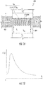
- FIG. 1 depicts a simplified example of a magnetic circuit to illustrate the concept of a magnetic flux diverter 300 as employed in the embodiments described herein.
- the magnetic flux diverter 300 can be understood as a conventional electromagnetic device that includes a saturable ferromagnetic material or core 302 (or a portion thereof) with a winding 304 wrapped around it. As a current (called a control current Ic) is passed through the winding 304, the magnetic properties of the ferromagnetic material or core 302 will vary to the point of saturation. To appreciate the operation of the magnetic flux diverter, discussion of the theory will be of assistance.
- the relative magnetic permeability ⁇ r is a function of the magnetic flux intensity.
- the magnetic field intensity is proportional to the current I c in the coil 304.
- the relative magnetic permeability ⁇ r varies with the current I c .
- This phenomenon is depicted in the graph of FIG 1B .
- the magnetic flux ⁇ is proportional to the relative magnetic permeability ⁇ r , which in turn is proportional to the control current I c . Therefore, as the I c increases, the permeability decreases and the reluctance for magnetic flux also increases. This characteristic of the magnetic diverter and the controllable saturation facilitates control of the magnetic flux in the described embodiments.
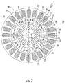
- FIG. 2 is a partial axial cross sectional view of a permanent magnet (PM) dynamoelectric machine 1 according to one possible embodiment.
- the machine 1 has a bearing 3 (See FIG. 4 ) disposed on a central shaft 2 coupled to a PM rotor assembly 6.
- the PM rotor assembly 6 comprises multiple PMs 4 arranged and mounted about its outer annular periphery 10.
- FIG. 2 shows the PM rotor assembly 6 with sixteen PMs 4.
- PMs 4 are arranged in radial direction and magnetized tangentially, that is, the PMs4 are trapezoidal or rectangular in shape, having two longer sides in radial direction.
- PMs 4 i.e., magnetization vector
- the polarity of PMs 4 is shown in FIG. 2 .
- the rotor assembly 6 may be constructed of any variety of ferromagnetic materials including, but not limited to steel laminations, sintered magnetic powder material, or solid ferromagnetic material such a steel. In one embodiment steel laminations are employed. In another the rotor assembly is machined from a steel block.
- PMs 4 can be also arranged at greater angle than zero degrees with respect the rotor radius or can have different cross section than rectangular. The number of PMs is typically even to create pole pairs. The minimum number of PMs 4 is two and the maximum number depends on the room available and the size of the PMs 4.
- the outer stator assembly 20 has multiple ferromagnetic stator teeth 21 coupled to a ferromagnetic stator core 22, and arranged around the periphery of the stator core 22, one stator tooth 21 for each of the poles of the stator assembly 20.
- a distal end 23 of each stator tooth 21 is proximate the outer annular periphery 10 of the rotor assembly 6.
- a small outer air gap 12 exists between the outer annular periphery 10 and the stator teeth 21.
- the stator assembly 20 also has multiple stator coils 24 mounted in slots 26 between the stator teeth 21.
- the ferromagnetic stator core 22 and stator teeth 21 may be constructed of any variety of ferromagnetic materials including, but not limited to steel laminations, sintered magnetic powder material, or solid ferromagnetic material such a steel. In one embodiment steel laminations are employed.
- the stator winding 24, also called an armature winding, is typically a three-phase winding. However, it should be understood that any number of phases can be designed. The minimum number of phases is one.
- an inner stator assembly shown generally as 30, is depicted concentric with and radially inward of the rotor assembly 6.
- the inner stator assembly 30 has a ferromagnetic stator core 32 with stator teeth 31 having distal ends 33 forming closed winding slots 36.
- An outer annular periphery 35 of the inner stator core 32 is proximate the inner periphery 14 of the PMs 4 of rotor assembly 6. Thereby, forming a small inner airgap 16 between the annular periphery 35 of the inner stator 30 and the inner periphery 14 of the rotor assembly 6.
- the inner stator assembly 30 also has an inner stator coil or control coil 34 wound in the slots 36 of the inner stator assembly 30.
- the inner stator coil 34 is fed with a current to control air gap magnetic flux ( ⁇ g ) generated by the PMs 4 across the air gap 16 through the inner stator 30.
- the current in the inner stator coil 30 is also termed the control current ( I c ).
- Application of a control current ( I c ) to the control coils 34 at least partially magnetically saturates the inner stator 30 to reduce air gap magnetic flux ( ⁇ g ), thereby increasing magnetic flux linkage ( ⁇ M ) between the PMs 4 and the outer stator coils 24 and increasing generated electromagnetic force (EMF) at lower angular velocity levels of the rotor assembly.
- the inner stator assembly 30 may be constructed of any variety of ferromagnetic materials including, but not limited to steel laminations, sintered magnetic powder material, or solid ferromagnetic material such steel. In one embodiment steel laminations are employed.
- a PM dynamoelectric machine 1 As may be employed in the embodiments. To better appreciate the application of the embodiments discussion of the operation of a PM dynamoelectric machine 1 as a motor and generator is provided.
- a motor drive (not shown) supplies controlled multiphase electrical power to the stator coils 24.
- the rotating field in the stator coils 24 causes the rotor assembly 6 to rotate in synchronization and thereby rotate the drive shaft 2.
- Fixed excitation flux provided by the PMs 4 in the rotor assembly 6 limits the use of the machine 1.
- the electrical current and voltage are limited by the constraints of the motor drive and constrains of the motor windings .
- the torque capabilities of the dynamoelectric machine 1 may readily be controlled by controlling the magnetic flux linkage ⁇ M and the q-axis armature current I aq .
- a prime mover (not shown) coupled to the drive shaft 2 rotates the PM rotor assembly 6.
- a magnetic flux linkage ( ⁇ M ) between the PMs 4 and the stator coils 24 of the stator assembly 20
- the rotating magnetic field that the rotating PMs 4 generates causes magnetic excitation flux to flow through the stator coils 24, thereby generating multiphase electrical power in the stator coils 24.
- Fixed excitation flux provided by the PMs 4 in the rotor assembly 6 limits the use of the machine 1, since electromotive force (EMF) that the machine 2 generates is proportional to the rate of change of magnetic flux passing through the stator coils 20 and this rate of change is proportional to the angular velocity of the rotor assembly 6.
- EMF electromotive force
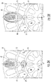
- Figs. 3A and 3B depict a partial cross section of the PM machine 1 with magnetic flux regulation according to an embodiment.
- the machine 1 includes the outer stator assembly 20 and inner stator assembly 30 and PM rotor assembly 6 between the stators assemblies 20, 30 as described above.
- This ferromagnetic bridge 37 adjacent to the air gap 16 with the inner stator coil 34 forms a magnetic flux diverter 300 (as described with respect to Figure 1 ) that is operative with the control current I c to divert magnetic flux excited by the PMs 4.
- the inner air gap between the PM rotor assembly 6 and inner stator assembly 30
- the outer air gap i.e., the air gap between the rotor assembly and outer stator assembly 20.
- EMF electromotive force
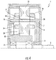
- FIG. 4 is a partial radial or longitudinal cross section of the permanent magnet (PM) dynamoelectric machine 1 according to one possible embodiment.
- the machine 1 has a bearing 3 mounted central shaft 2 coupled to a PM rotor assembly 6.
- the PM rotor assembly 6 is cup or bowl shaped with a base 7 and side 8.
- the side 8 is proximal to each of the stator core 22 and 32 for the outer stator 20 and inner stator 30, respectively.
- the sides also include the multiple PMs 4 mounted about its annular periphery 10.
- the PMs 4 are arranged in radial direction and magnetized tangentially.
- the sides 8 are formed of ferromagnetic material (rotor core) between PMs 4. Magnetic poles are created in the ferromagnetic material between PMs 4.
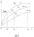
- FIG. 5 is a graphical representation of voltage V as a function of three different velocities n 1 , n 2 and n 3 (where n 3 , ⁇ n 2 ⁇ n 1) of the PM machines 1.
- Line 110 represents velocity n 1
- line 112 represents velocity n 2
- line 114 represents velocity n 3 .
- Line 116 represents a constant reference voltage output V const for application of respective control currents I c 1 , I c 2 and I c 3 to the stator coil 34 of the inner stator 30.
- the controller providing the control current I c become inoperative (e.g., open circuit)
- the terminal voltage of the generator would be at its minimum value. If the control winding is shorted or partially shorted, the magnetic saturation of the diverter is reduced and the terminal voltage also decreases.
- the control current I c is varied and maintained a desired level as shown in FIG. 5 . For example, if the speed increases from n 3 to n 1 , the control current must be reduced from I c 3 to I c 1 to reduce the reluctance of flux diverter and decrease the magnetic flux linked with the outer stator coil 24.
- This novel double-stator PM machine can also operate as a synchronous motor with flux weakening control, e.g., in electric traction vehicle or electric landing gears of aircraft and the like.
- FIGs. 6A and 6B provide a graphical representation of configurations for the inner stator coil 34 of the inner stator 30.
- the diagram depicts the inner stator coil 34 as the stator coil is wound through the closed stator teeth of the inner stator 30.
- the control current I c is depicted with directions (represented by arrows 41), as provided by control current source or regulator 52 (See FIG. 7 ). It should be appreciated that there may be a plurality of inner stator coils 34 connected and grouped in various arrangements.
- the connections of the inner stator coil 34 may include a serial connection of the control coils 34 with adjacent control coils 34 in phase opposition, such as a first side of each control coil 34, connecting to a first side of a preceding adjacent control coil 24 in the series connection and a second side of each control coil 24 opposite the first side connecting to second side of the following adjacent control coil 24 in the series connection.
- These kinds of arrangements may be advantageous depending on the type of excitation employed for the control current I c .
- the currents in the neighboring sides of coils are in opposite direction, i.e., the input terminal of every second coil is connected to the input terminal of the next coil (or the output terminal of every second coil is connected to the output terminal of the next coil).
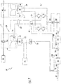
- FIG. 7 is a high-level schematic representation of an electrical power generating system 50 according to a possible embodiment. While in an embodiment the description of the systems and applications for the dynamoelectric machine 1 are made with respect to a power generation system, it should be appreciated that other configurations and systems employing the dynamoelectric machine 1 are possible and within the scope of the claims including, for example motor systems, motor control system and the like.
- the electrical power generating system may include a prime mover 48, such as an aeronautical gas turbine engine, and the PM dynamoelectric machine with magnetically saturable ferromagnetic second stator 30 as described herein such as the PM dynamoelectric machine 1 as shown in FIGs. 2-4 .
- the prime mover 48 drives the machine 1, by way of a drive shaft 2.
- An auxiliary power source 51 supplies power to a control current regulator 52 by way of an auxiliary power bus 54.
- the auxiliary power source 51 may be AC or DC. It may include a multiphase AC auxiliary PM dynamoelectric machine driven by the drive shaft 2 and a multiphase AC rectifier 58 that receives multiphase AC power from the auxiliary machine 56 on a multiphase AC auxiliary power bus 60 and converts it to DC power on the auxiliary power bus 54.
- the auxiliary power source 51 may be a separately powered source or a battery with chopper shown as 51'.
- the auxiliary machine 56 may be any conventional dynamoelectric machine operable to generate power and power the auxiliary bus 54.
- the control current regulator 52 preferably comprises an H-bridge circuit.
- the regulator 52 supplies control current I c to control coil(s) i.e., stator coil 34 of the inner stator 20 in the machine 1 by way of a control current supply bus 62.
- a control current sensor 64 monitors the level of control current passing through the control current supply bus 62 and generates a corresponding control current feedback signal representative of its level on a control current feedback signal line 66.
- a multiphase AC main power rectifier 68 receives multiphase AC power from the stator coils 24 of the machine 1 on a multiphase AC main power bus 70.
- the AC power is converted to DC main power on a DC main power bus 72 for supply to a DC load 74.
- a sensor detects an operating characteristic of the dynamoelectric machine 1, for example, output voltage, output current, frequency and the like. Likewise, in a motor application, operating characteristics such as motor speed, torque and the like may be measured.
- One or more main power voltage sensor(s) 76 monitor the level of voltage on the AC bus 72 and/or DC main power bus 72 and generates a corresponding voltage feedback signal (DC shown) representative of its level on a main power voltage feedback signal line 78.
- the AC power can also be converted to the DC power and then again inverted to the AC power of different frequency and different voltage level.
- a voltage signal comparator 80 receives a main power voltage reference signal on a voltage reference line 82 and compares it to the main power voltage feedback signal on the main power voltage signal line 78 to generate a voltage difference signal representative of the difference between them on a voltage difference signal line 84.
- a main power voltage feedback proportional-plus-integral (PI) controller 86 receives the voltage difference signal on the voltage difference signal line 84 and converts it to a stable control current reference signal on a control current reference signal line 88.
- PI proportional-plus-integral
- a current signal comparator 90 compares the control current reference signal on the control current reference signal line 88 with the control current feedback signal on the control current feedback signal line 66 to generate a current difference signal on a current difference signal line 92.
- a control current feedback PI controller 94 receives the current difference signal on the current difference signal line 92 and converts it to a stable control current regulating signal on a control current regulating signal line 96.
- a pulse width modulator (PWM) circuit 98 receives the control current regulating signal on a control current regulating signal line 96 and generates corresponding PWM control signals on a PWM control signal bus 100.
- a gate drive circuit 102 receives the PWM control signals on a PWM control signal bus 100 and generates corresponding gate drive signals on a gate drive signal bus 104.
- the control current regulator 52 receives the gate drive signals on the gate drive signal bus 104 to produce a level of the control current I c on the control current supply bus 62 responsive to a main power voltage feedback loop 106 and a control current feedback loop 108.
- FIG.8 where a flowchart of the method 200 of controlling the flux in a PM dynamoelectric machine is depicted.
- the method is initiated at process step 205 by providing a dynamoelectric machine 1 with a second stator assembly 30 including a stator winding 34 in accordance with the embodiments described herein.
- an operating characteristic e.g., voltage, current output from a generator or speed, torque and the like for motor applications, of the dynamoelectric machine is measured.
- the control current Ic in the stator winding 34 is applied at process step 215 and varied to maintain the operating characteristic at a desired level as depicted at process step 220.
Landscapes
- Engineering & Computer Science (AREA)
- Power Engineering (AREA)
- Synchronous Machinery (AREA)
- Iron Core Of Rotating Electric Machines (AREA)
Applications Claiming Priority (1)
| Application Number | Priority Date | Filing Date | Title |
|---|---|---|---|
| US15/400,180 US10483891B2 (en) | 2017-01-06 | 2017-01-06 | Double stator permanent magnet machine with magnetic flux regulation |
Publications (2)
| Publication Number | Publication Date |
|---|---|
| EP3346590A1 true EP3346590A1 (de) | 2018-07-11 |
| EP3346590B1 EP3346590B1 (de) | 2020-12-23 |
Family
ID=60937648
Family Applications (1)
| Application Number | Title | Priority Date | Filing Date |
|---|---|---|---|
| EP18150561.1A Active EP3346590B1 (de) | 2017-01-06 | 2018-01-08 | Doppelstator-permanentmagnetmaschine mit magnetflussregulierung |
Country Status (2)
| Country | Link |
|---|---|
| US (1) | US10483891B2 (de) |
| EP (1) | EP3346590B1 (de) |
Cited By (2)
| Publication number | Priority date | Publication date | Assignee | Title |
|---|---|---|---|---|
| WO2020245392A1 (en) * | 2019-06-05 | 2020-12-10 | Universiteit Gent | An electrical machine comprising an integrated magnetic torsion spring |
| FR3105885A1 (fr) * | 2019-12-26 | 2021-07-02 | Thales | Système d'entraînement électrique à deux étages |
Families Citing this family (10)
| Publication number | Priority date | Publication date | Assignee | Title |
|---|---|---|---|---|
| CN102097894B (zh) * | 2011-01-30 | 2012-07-25 | 陈维加 | 一种交流发电机的发电方法及其发电机 |
| CN104967378B (zh) * | 2015-05-27 | 2018-10-23 | 北京金风科创风电设备有限公司 | 风力发电机振动和噪声抑制方法及装置 |
| US10581357B2 (en) * | 2018-05-11 | 2020-03-03 | Abb Schweiz Ag | Rotating direct current power supply for synchronous machines |
| US10651770B2 (en) | 2018-08-29 | 2020-05-12 | Hamilton Sundstrand Corporation | Direct current voltage regulation of a six-phase permanent magnet generator |
| US10396680B1 (en) | 2018-08-29 | 2019-08-27 | Hamilton Sundstrand Corporation | Direct current voltage regulation of permanent magnet generator |
| US10778127B2 (en) | 2018-09-10 | 2020-09-15 | Hamilton Sundstrand Corporation | Direct current voltage regulation of permanent magnet generator |
| US10855216B2 (en) | 2018-09-10 | 2020-12-01 | Hamilton Sundstrand Corporation | Voltage regulation of multi-phase permanent magnet generator |
| US10608567B1 (en) * | 2019-02-22 | 2020-03-31 | GM Global Technology Operations LLC | Determination of demagnetized torque capability in real-time for electric motor in propulsion system |
| WO2023108893A1 (zh) * | 2021-12-17 | 2023-06-22 | 淮安威灵电机制造有限公司 | 定子组件、电机和电器设备 |
| AT528069A1 (de) * | 2024-08-01 | 2025-08-15 | Avl List Gmbh | Elektromotor und Fahrzeug aufweisend einen Elektromotor |
Citations (5)
| Publication number | Priority date | Publication date | Assignee | Title |
|---|---|---|---|---|
| JPH0345150A (ja) * | 1989-07-07 | 1991-02-26 | Sawafuji Electric Co Ltd | ブラシレス磁石発電機 |
| JP2004260970A (ja) * | 2003-02-27 | 2004-09-16 | Toyota Motor Corp | 電動機および電動機システム |
| US7791245B1 (en) * | 2009-03-24 | 2010-09-07 | Gm Global Technology Operations, Inc. | Optimized electric machine for smart actuators |
| JP2014220884A (ja) * | 2013-05-07 | 2014-11-20 | 株式会社ジェイテクト | 回転電機 |
| EP2985422A1 (de) * | 2014-08-12 | 2016-02-17 | Hamilton Sundstrand Corporation | Starter-generatormodule für gasturbinenmotoren |
Family Cites Families (15)
| Publication number | Priority date | Publication date | Assignee | Title |
|---|---|---|---|---|
| ATE166500T1 (de) * | 1994-11-10 | 1998-06-15 | Voith Turbo Kg | Transversalflussmaschine |
| DE19838378A1 (de) * | 1998-08-24 | 2000-03-02 | Magnet Motor Gmbh | Elektrische Maschine mit Dauermagneten |
| US6727618B1 (en) * | 2002-06-10 | 2004-04-27 | The United States Of America, As Represented By The Administrator Of National Aeronautics And Space Administration | Bearingless switched reluctance motor |
| CN100502206C (zh) * | 2002-09-18 | 2009-06-17 | 尼格麦康控制系统股份有限公司 | 定子磁极铁心数量大于转子极靴数量的电动机/发电机 |
| US6965183B2 (en) | 2003-05-27 | 2005-11-15 | Pratt & Whitney Canada Corp. | Architecture for electric machine |
| US7859231B2 (en) * | 2008-04-02 | 2010-12-28 | Hamilton Sundstrand Corporation | Permanent magnet electric generator with variable magnet flux excitation |
| US7777384B2 (en) | 2008-04-02 | 2010-08-17 | Hamilton Sundstrand Corporation | Permanent magnet dynamoelectric machine with variable magnetic flux excitation |
| US7843155B2 (en) | 2008-04-10 | 2010-11-30 | Hamilton Sundstrand Corporation | Direct flux regulated permanent magnet brushless motor utilizing sensorless control |
| JP5477161B2 (ja) * | 2010-05-20 | 2014-04-23 | 株式会社デンソー | ダブルステータ型モータ |
| KR101131743B1 (ko) * | 2010-06-23 | 2012-04-05 | 주식회사 아모텍 | 드럼세탁기의 직결형 구동장치 |
| NL1038151C2 (en) | 2010-08-05 | 2012-02-07 | Martin Jacobus Hoeijmakers | Rotating electromechanical converter. |
| JP5591099B2 (ja) * | 2010-12-28 | 2014-09-17 | 三菱電機株式会社 | 圧縮機および冷凍サイクル装置 |
| JP5472254B2 (ja) | 2011-10-21 | 2014-04-16 | 株式会社デンソー | ダブルステータ型モータ |
| JP2016111842A (ja) * | 2014-12-08 | 2016-06-20 | 株式会社デンソー | ダブルステータ型回転電機 |
| CN106026597B (zh) | 2016-07-11 | 2018-08-21 | 江苏大学 | 内置磁障式磁场增强型永磁无刷电机 |
-
2017
- 2017-01-06 US US15/400,180 patent/US10483891B2/en active Active
-
2018
- 2018-01-08 EP EP18150561.1A patent/EP3346590B1/de active Active
Patent Citations (5)
| Publication number | Priority date | Publication date | Assignee | Title |
|---|---|---|---|---|
| JPH0345150A (ja) * | 1989-07-07 | 1991-02-26 | Sawafuji Electric Co Ltd | ブラシレス磁石発電機 |
| JP2004260970A (ja) * | 2003-02-27 | 2004-09-16 | Toyota Motor Corp | 電動機および電動機システム |
| US7791245B1 (en) * | 2009-03-24 | 2010-09-07 | Gm Global Technology Operations, Inc. | Optimized electric machine for smart actuators |
| JP2014220884A (ja) * | 2013-05-07 | 2014-11-20 | 株式会社ジェイテクト | 回転電機 |
| EP2985422A1 (de) * | 2014-08-12 | 2016-02-17 | Hamilton Sundstrand Corporation | Starter-generatormodule für gasturbinenmotoren |
Non-Patent Citations (2)
| Title |
|---|
| JACEK F GIERAS: "PM synchronous generators with hybrid excitation systems and voltage control Capabilities: A review", ELECTRICAL MACHINES (ICEM), 2012 XXTH INTERNATIONAL CONFERENCE ON, IEEE, 2 September 2012 (2012-09-02), pages 2573 - 2579, XP032465070, ISBN: 978-1-4673-0143-5, DOI: 10.1109/ICELMACH.2012.6350248 * |
| WANG YUNCHONG ET AL: "A Novel Structure of Dual-Stator Hybrid Excitation Synchronous Motor", IEEE TRANSACTIONS ON APPLIED SUPERCONDUCTIVITY, IEEE SERVICE CENTER, LOS ALAMITOS, CA, US, vol. 26, no. 4, 1 June 2016 (2016-06-01), pages 1 - 5, XP011611065, ISSN: 1051-8223, [retrieved on 20160520], DOI: 10.1109/TASC.2016.2533263 * |
Cited By (2)
| Publication number | Priority date | Publication date | Assignee | Title |
|---|---|---|---|---|
| WO2020245392A1 (en) * | 2019-06-05 | 2020-12-10 | Universiteit Gent | An electrical machine comprising an integrated magnetic torsion spring |
| FR3105885A1 (fr) * | 2019-12-26 | 2021-07-02 | Thales | Système d'entraînement électrique à deux étages |
Also Published As
| Publication number | Publication date |
|---|---|
| EP3346590B1 (de) | 2020-12-23 |
| US20180198395A1 (en) | 2018-07-12 |
| US10483891B2 (en) | 2019-11-19 |
Similar Documents
| Publication | Publication Date | Title |
|---|---|---|
| EP3346590B1 (de) | Doppelstator-permanentmagnetmaschine mit magnetflussregulierung | |
| EP3376650A1 (de) | Permanentmagnet-starter-generator mit magnetflussregulierung | |
| US9231504B2 (en) | Electrical control system | |
| EP2107664B1 (de) | Elektrischer Generator mit Permanentmagneten mit verstellbarer Magnetflussstimulierung | |
| EP1829187B1 (de) | Sättigungsregelung einer elektrischen maschine | |
| EP2782226B1 (de) | Flussgeregelte PM-Läufer eines elektrische Maschine | |
| US10090742B2 (en) | Rotating electric machine | |
| EP2107665A2 (de) | Dynamo-Maschine mit einem Permanentmagneten mit verstellbarer Magnetflussstimulierung | |
| JPS59129558A (ja) | 可変速回転電機 | |
| EP3316459B1 (de) | Elektromotoren | |
| JP6668844B2 (ja) | 回転電機 | |
| CN111247736B (zh) | 防止电机中的永磁体消磁的系统和方法 | |
| JP2018093695A (ja) | モータとその制御装置 | |
| JP2003032978A (ja) | 回転電機 | |
| US9000648B2 (en) | Asymmetrical reluctance machine | |
| EP2814146A2 (de) | Dauermagnetsynchronmaschinen mit magnetischer Flusssteuerung | |
| WO2018101158A1 (ja) | モータとその制御装置 | |
| GB2468695A (en) | A stator assembly incorporating permanent magnets and wound field poles for an inductor machine. | |
| US20170005555A1 (en) | Asymmetric salient permanent magnet synchronous machine | |
| JP2018117398A (ja) | モータとその制御装置 | |
| CN110391706B (zh) | 旋转电机 | |
| Ishihara et al. | Improving the efficiency of switched reluctance motors using a step-skewed rotor | |
| JP6323220B2 (ja) | 同期電動機の駆動装置 | |
| US10770999B2 (en) | Brushless, self-excited synchronous field-winding machine | |
| RU2652102C1 (ru) | Вентильный электродвигатель |
Legal Events
| Date | Code | Title | Description |
|---|---|---|---|
| PUAI | Public reference made under article 153(3) epc to a published international application that has entered the european phase |
Free format text: ORIGINAL CODE: 0009012 |
|
| STAA | Information on the status of an ep patent application or granted ep patent |
Free format text: STATUS: THE APPLICATION HAS BEEN PUBLISHED |
|
| AK | Designated contracting states |
Kind code of ref document: A1 Designated state(s): AL AT BE BG CH CY CZ DE DK EE ES FI FR GB GR HR HU IE IS IT LI LT LU LV MC MK MT NL NO PL PT RO RS SE SI SK SM TR |
|
| AX | Request for extension of the european patent |
Extension state: BA ME |
|
| STAA | Information on the status of an ep patent application or granted ep patent |
Free format text: STATUS: REQUEST FOR EXAMINATION WAS MADE |
|
| 17P | Request for examination filed |
Effective date: 20190111 |
|
| RBV | Designated contracting states (corrected) |
Designated state(s): AL AT BE BG CH CY CZ DE DK EE ES FI FR GB GR HR HU IE IS IT LI LT LU LV MC MK MT NL NO PL PT RO RS SE SI SK SM TR |
|
| STAA | Information on the status of an ep patent application or granted ep patent |
Free format text: STATUS: EXAMINATION IS IN PROGRESS |
|
| 17Q | First examination report despatched |
Effective date: 20190531 |
|
| RIC1 | Information provided on ipc code assigned before grant |
Ipc: H02P 9/30 20060101ALI20200416BHEP Ipc: H02K 16/04 20060101AFI20200416BHEP Ipc: H02P 21/06 20160101ALI20200416BHEP Ipc: H02K 21/12 20060101ALI20200416BHEP Ipc: H02K 21/04 20060101ALI20200416BHEP |
|
| GRAP | Despatch of communication of intention to grant a patent |
Free format text: ORIGINAL CODE: EPIDOSNIGR1 |
|
| STAA | Information on the status of an ep patent application or granted ep patent |
Free format text: STATUS: GRANT OF PATENT IS INTENDED |
|
| INTG | Intention to grant announced |
Effective date: 20200619 |
|
| GRAS | Grant fee paid |
Free format text: ORIGINAL CODE: EPIDOSNIGR3 |
|
| GRAA | (expected) grant |
Free format text: ORIGINAL CODE: 0009210 |
|
| STAA | Information on the status of an ep patent application or granted ep patent |
Free format text: STATUS: THE PATENT HAS BEEN GRANTED |
|
| AK | Designated contracting states |
Kind code of ref document: B1 Designated state(s): AL AT BE BG CH CY CZ DE DK EE ES FI FR GB GR HR HU IE IS IT LI LT LU LV MC MK MT NL NO PL PT RO RS SE SI SK SM TR |
|
| REG | Reference to a national code |
Ref country code: GB Ref legal event code: FG4D |
|
| REG | Reference to a national code |
Ref country code: DE Ref legal event code: R096 Ref document number: 602018010947 Country of ref document: DE |
|
| REG | Reference to a national code |
Ref country code: AT Ref legal event code: REF Ref document number: 1348673 Country of ref document: AT Kind code of ref document: T Effective date: 20210115 |
|
| REG | Reference to a national code |
Ref country code: IE Ref legal event code: FG4D |
|
| PG25 | Lapsed in a contracting state [announced via postgrant information from national office to epo] |
Ref country code: GR Free format text: LAPSE BECAUSE OF FAILURE TO SUBMIT A TRANSLATION OF THE DESCRIPTION OR TO PAY THE FEE WITHIN THE PRESCRIBED TIME-LIMIT Effective date: 20210324 Ref country code: NO Free format text: LAPSE BECAUSE OF FAILURE TO SUBMIT A TRANSLATION OF THE DESCRIPTION OR TO PAY THE FEE WITHIN THE PRESCRIBED TIME-LIMIT Effective date: 20210323 Ref country code: FI Free format text: LAPSE BECAUSE OF FAILURE TO SUBMIT A TRANSLATION OF THE DESCRIPTION OR TO PAY THE FEE WITHIN THE PRESCRIBED TIME-LIMIT Effective date: 20201223 Ref country code: RS Free format text: LAPSE BECAUSE OF FAILURE TO SUBMIT A TRANSLATION OF THE DESCRIPTION OR TO PAY THE FEE WITHIN THE PRESCRIBED TIME-LIMIT Effective date: 20201223 |
|
| REG | Reference to a national code |
Ref country code: AT Ref legal event code: MK05 Ref document number: 1348673 Country of ref document: AT Kind code of ref document: T Effective date: 20201223 |
|
| REG | Reference to a national code |
Ref country code: NL Ref legal event code: MP Effective date: 20201223 |
|
| PG25 | Lapsed in a contracting state [announced via postgrant information from national office to epo] |
Ref country code: BG Free format text: LAPSE BECAUSE OF FAILURE TO SUBMIT A TRANSLATION OF THE DESCRIPTION OR TO PAY THE FEE WITHIN THE PRESCRIBED TIME-LIMIT Effective date: 20210323 Ref country code: LV Free format text: LAPSE BECAUSE OF FAILURE TO SUBMIT A TRANSLATION OF THE DESCRIPTION OR TO PAY THE FEE WITHIN THE PRESCRIBED TIME-LIMIT Effective date: 20201223 Ref country code: SE Free format text: LAPSE BECAUSE OF FAILURE TO SUBMIT A TRANSLATION OF THE DESCRIPTION OR TO PAY THE FEE WITHIN THE PRESCRIBED TIME-LIMIT Effective date: 20201223 |
|
| PG25 | Lapsed in a contracting state [announced via postgrant information from national office to epo] |
Ref country code: HR Free format text: LAPSE BECAUSE OF FAILURE TO SUBMIT A TRANSLATION OF THE DESCRIPTION OR TO PAY THE FEE WITHIN THE PRESCRIBED TIME-LIMIT Effective date: 20201223 Ref country code: NL Free format text: LAPSE BECAUSE OF FAILURE TO SUBMIT A TRANSLATION OF THE DESCRIPTION OR TO PAY THE FEE WITHIN THE PRESCRIBED TIME-LIMIT Effective date: 20201223 |
|
| REG | Reference to a national code |
Ref country code: LT Ref legal event code: MG9D |
|
| PG25 | Lapsed in a contracting state [announced via postgrant information from national office to epo] |
Ref country code: SM Free format text: LAPSE BECAUSE OF FAILURE TO SUBMIT A TRANSLATION OF THE DESCRIPTION OR TO PAY THE FEE WITHIN THE PRESCRIBED TIME-LIMIT Effective date: 20201223 Ref country code: LT Free format text: LAPSE BECAUSE OF FAILURE TO SUBMIT A TRANSLATION OF THE DESCRIPTION OR TO PAY THE FEE WITHIN THE PRESCRIBED TIME-LIMIT Effective date: 20201223 Ref country code: CZ Free format text: LAPSE BECAUSE OF FAILURE TO SUBMIT A TRANSLATION OF THE DESCRIPTION OR TO PAY THE FEE WITHIN THE PRESCRIBED TIME-LIMIT Effective date: 20201223 Ref country code: EE Free format text: LAPSE BECAUSE OF FAILURE TO SUBMIT A TRANSLATION OF THE DESCRIPTION OR TO PAY THE FEE WITHIN THE PRESCRIBED TIME-LIMIT Effective date: 20201223 Ref country code: PT Free format text: LAPSE BECAUSE OF FAILURE TO SUBMIT A TRANSLATION OF THE DESCRIPTION OR TO PAY THE FEE WITHIN THE PRESCRIBED TIME-LIMIT Effective date: 20210423 Ref country code: RO Free format text: LAPSE BECAUSE OF FAILURE TO SUBMIT A TRANSLATION OF THE DESCRIPTION OR TO PAY THE FEE WITHIN THE PRESCRIBED TIME-LIMIT Effective date: 20201223 Ref country code: SK Free format text: LAPSE BECAUSE OF FAILURE TO SUBMIT A TRANSLATION OF THE DESCRIPTION OR TO PAY THE FEE WITHIN THE PRESCRIBED TIME-LIMIT Effective date: 20201223 |
|
| PG25 | Lapsed in a contracting state [announced via postgrant information from national office to epo] |
Ref country code: AT Free format text: LAPSE BECAUSE OF FAILURE TO SUBMIT A TRANSLATION OF THE DESCRIPTION OR TO PAY THE FEE WITHIN THE PRESCRIBED TIME-LIMIT Effective date: 20201223 Ref country code: PL Free format text: LAPSE BECAUSE OF FAILURE TO SUBMIT A TRANSLATION OF THE DESCRIPTION OR TO PAY THE FEE WITHIN THE PRESCRIBED TIME-LIMIT Effective date: 20201223 |
|
| REG | Reference to a national code |
Ref country code: CH Ref legal event code: PL |
|
| REG | Reference to a national code |
Ref country code: DE Ref legal event code: R097 Ref document number: 602018010947 Country of ref document: DE |
|
| PG25 | Lapsed in a contracting state [announced via postgrant information from national office to epo] |
Ref country code: IS Free format text: LAPSE BECAUSE OF FAILURE TO SUBMIT A TRANSLATION OF THE DESCRIPTION OR TO PAY THE FEE WITHIN THE PRESCRIBED TIME-LIMIT Effective date: 20210423 Ref country code: LU Free format text: LAPSE BECAUSE OF NON-PAYMENT OF DUE FEES Effective date: 20210108 Ref country code: MC Free format text: LAPSE BECAUSE OF FAILURE TO SUBMIT A TRANSLATION OF THE DESCRIPTION OR TO PAY THE FEE WITHIN THE PRESCRIBED TIME-LIMIT Effective date: 20201223 |
|
| REG | Reference to a national code |
Ref country code: BE Ref legal event code: MM Effective date: 20210131 |
|
| PG25 | Lapsed in a contracting state [announced via postgrant information from national office to epo] |
Ref country code: AL Free format text: LAPSE BECAUSE OF FAILURE TO SUBMIT A TRANSLATION OF THE DESCRIPTION OR TO PAY THE FEE WITHIN THE PRESCRIBED TIME-LIMIT Effective date: 20201223 Ref country code: IT Free format text: LAPSE BECAUSE OF FAILURE TO SUBMIT A TRANSLATION OF THE DESCRIPTION OR TO PAY THE FEE WITHIN THE PRESCRIBED TIME-LIMIT Effective date: 20201223 |
|
| PLBE | No opposition filed within time limit |
Free format text: ORIGINAL CODE: 0009261 |
|
| STAA | Information on the status of an ep patent application or granted ep patent |
Free format text: STATUS: NO OPPOSITION FILED WITHIN TIME LIMIT |
|
| PG25 | Lapsed in a contracting state [announced via postgrant information from national office to epo] |
Ref country code: LI Free format text: LAPSE BECAUSE OF NON-PAYMENT OF DUE FEES Effective date: 20210131 Ref country code: CH Free format text: LAPSE BECAUSE OF NON-PAYMENT OF DUE FEES Effective date: 20210131 Ref country code: DK Free format text: LAPSE BECAUSE OF FAILURE TO SUBMIT A TRANSLATION OF THE DESCRIPTION OR TO PAY THE FEE WITHIN THE PRESCRIBED TIME-LIMIT Effective date: 20201223 |
|
| 26N | No opposition filed |
Effective date: 20210924 |
|
| PG25 | Lapsed in a contracting state [announced via postgrant information from national office to epo] |
Ref country code: IE Free format text: LAPSE BECAUSE OF NON-PAYMENT OF DUE FEES Effective date: 20210108 Ref country code: ES Free format text: LAPSE BECAUSE OF FAILURE TO SUBMIT A TRANSLATION OF THE DESCRIPTION OR TO PAY THE FEE WITHIN THE PRESCRIBED TIME-LIMIT Effective date: 20201223 |
|
| PG25 | Lapsed in a contracting state [announced via postgrant information from national office to epo] |
Ref country code: SI Free format text: LAPSE BECAUSE OF FAILURE TO SUBMIT A TRANSLATION OF THE DESCRIPTION OR TO PAY THE FEE WITHIN THE PRESCRIBED TIME-LIMIT Effective date: 20201223 |
|
| PG25 | Lapsed in a contracting state [announced via postgrant information from national office to epo] |
Ref country code: IS Free format text: LAPSE BECAUSE OF FAILURE TO SUBMIT A TRANSLATION OF THE DESCRIPTION OR TO PAY THE FEE WITHIN THE PRESCRIBED TIME-LIMIT Effective date: 20210423 |
|
| PG25 | Lapsed in a contracting state [announced via postgrant information from national office to epo] |
Ref country code: BE Free format text: LAPSE BECAUSE OF NON-PAYMENT OF DUE FEES Effective date: 20210131 |
|
| P01 | Opt-out of the competence of the unified patent court (upc) registered |
Effective date: 20230522 |
|
| PG25 | Lapsed in a contracting state [announced via postgrant information from national office to epo] |
Ref country code: CY Free format text: LAPSE BECAUSE OF FAILURE TO SUBMIT A TRANSLATION OF THE DESCRIPTION OR TO PAY THE FEE WITHIN THE PRESCRIBED TIME-LIMIT Effective date: 20201223 |
|
| PG25 | Lapsed in a contracting state [announced via postgrant information from national office to epo] |
Ref country code: HU Free format text: LAPSE BECAUSE OF FAILURE TO SUBMIT A TRANSLATION OF THE DESCRIPTION OR TO PAY THE FEE WITHIN THE PRESCRIBED TIME-LIMIT; INVALID AB INITIO Effective date: 20180108 |
|
| PG25 | Lapsed in a contracting state [announced via postgrant information from national office to epo] |
Ref country code: MK Free format text: LAPSE BECAUSE OF FAILURE TO SUBMIT A TRANSLATION OF THE DESCRIPTION OR TO PAY THE FEE WITHIN THE PRESCRIBED TIME-LIMIT Effective date: 20201223 |
|
| PG25 | Lapsed in a contracting state [announced via postgrant information from national office to epo] |
Ref country code: TR Free format text: LAPSE BECAUSE OF FAILURE TO SUBMIT A TRANSLATION OF THE DESCRIPTION OR TO PAY THE FEE WITHIN THE PRESCRIBED TIME-LIMIT Effective date: 20201223 |
|
| PG25 | Lapsed in a contracting state [announced via postgrant information from national office to epo] |
Ref country code: MT Free format text: LAPSE BECAUSE OF FAILURE TO SUBMIT A TRANSLATION OF THE DESCRIPTION OR TO PAY THE FEE WITHIN THE PRESCRIBED TIME-LIMIT Effective date: 20201223 |
|
| PGFP | Annual fee paid to national office [announced via postgrant information from national office to epo] |
Ref country code: GB Payment date: 20251219 Year of fee payment: 9 |
|
| PGFP | Annual fee paid to national office [announced via postgrant information from national office to epo] |
Ref country code: FR Payment date: 20251217 Year of fee payment: 9 |
|
| PGFP | Annual fee paid to national office [announced via postgrant information from national office to epo] |
Ref country code: DE Payment date: 20251217 Year of fee payment: 9 |