EP3346651A1 - Procédé et dispositif de répartition de sous-bandes - Google Patents
Procédé et dispositif de répartition de sous-bandes Download PDFInfo
- Publication number
- EP3346651A1 EP3346651A1 EP16848177.8A EP16848177A EP3346651A1 EP 3346651 A1 EP3346651 A1 EP 3346651A1 EP 16848177 A EP16848177 A EP 16848177A EP 3346651 A1 EP3346651 A1 EP 3346651A1
- Authority
- EP
- European Patent Office
- Prior art keywords
- band
- sub
- message
- target sub
- subframe
- Prior art date
- Legal status (The legal status is an assumption and is not a legal conclusion. Google has not performed a legal analysis and makes no representation as to the accuracy of the status listed.)
- Granted
Links
Images




Classifications
-
- H—ELECTRICITY
- H04—ELECTRIC COMMUNICATION TECHNIQUE
- H04W—WIRELESS COMMUNICATION NETWORKS
- H04W72/00—Local resource management
- H04W72/04—Wireless resource allocation
- H04W72/044—Wireless resource allocation based on the type of the allocated resource
- H04W72/0453—Resources in frequency domain, e.g. a carrier in FDMA
-
- H—ELECTRICITY
- H04—ELECTRIC COMMUNICATION TECHNIQUE
- H04L—TRANSMISSION OF DIGITAL INFORMATION, e.g. TELEGRAPHIC COMMUNICATION
- H04L5/00—Arrangements affording multiple use of the transmission path
- H04L5/003—Arrangements for allocating sub-channels of the transmission path
- H04L5/0044—Allocation of payload; Allocation of data channels, e.g. PDSCH or PUSCH
-
- H—ELECTRICITY
- H04—ELECTRIC COMMUNICATION TECHNIQUE
- H04L—TRANSMISSION OF DIGITAL INFORMATION, e.g. TELEGRAPHIC COMMUNICATION
- H04L5/00—Arrangements affording multiple use of the transmission path
- H04L5/003—Arrangements for allocating sub-channels of the transmission path
- H04L5/0053—Allocation of signalling, i.e. of overhead other than pilot signals
-
- H—ELECTRICITY
- H04—ELECTRIC COMMUNICATION TECHNIQUE
- H04L—TRANSMISSION OF DIGITAL INFORMATION, e.g. TELEGRAPHIC COMMUNICATION
- H04L5/00—Arrangements affording multiple use of the transmission path
- H04L5/003—Arrangements for allocating sub-channels of the transmission path
- H04L5/0058—Allocation criteria
- H04L5/0064—Rate requirement of the data, e.g. scalable bandwidth, data priority
-
- H—ELECTRICITY
- H04—ELECTRIC COMMUNICATION TECHNIQUE
- H04L—TRANSMISSION OF DIGITAL INFORMATION, e.g. TELEGRAPHIC COMMUNICATION
- H04L5/00—Arrangements affording multiple use of the transmission path
- H04L5/003—Arrangements for allocating sub-channels of the transmission path
- H04L5/0078—Timing of allocation
- H04L5/008—Timing of allocation once only, on installation
-
- H—ELECTRICITY
- H04—ELECTRIC COMMUNICATION TECHNIQUE
- H04L—TRANSMISSION OF DIGITAL INFORMATION, e.g. TELEGRAPHIC COMMUNICATION
- H04L5/00—Arrangements affording multiple use of the transmission path
- H04L5/0091—Signalling for the administration of the divided path, e.g. signalling of configuration information
- H04L5/0094—Indication of how sub-channels of the path are allocated
-
- H—ELECTRICITY
- H04—ELECTRIC COMMUNICATION TECHNIQUE
- H04W—WIRELESS COMMUNICATION NETWORKS
- H04W56/00—Synchronisation arrangements
- H04W56/004—Synchronisation arrangements compensating for timing error of reception due to propagation delay
- H04W56/0045—Synchronisation arrangements compensating for timing error of reception due to propagation delay compensating for timing error by altering transmission time
-
- H—ELECTRICITY
- H04—ELECTRIC COMMUNICATION TECHNIQUE
- H04W—WIRELESS COMMUNICATION NETWORKS
- H04W72/00—Local resource management
- H04W72/04—Wireless resource allocation
- H04W72/044—Wireless resource allocation based on the type of the allocated resource
- H04W72/0446—Resources in time domain, e.g. slots or frames
-
- H—ELECTRICITY
- H04—ELECTRIC COMMUNICATION TECHNIQUE
- H04W—WIRELESS COMMUNICATION NETWORKS
- H04W72/00—Local resource management
- H04W72/12—Wireless traffic scheduling
-
- H—ELECTRICITY
- H04—ELECTRIC COMMUNICATION TECHNIQUE
- H04W—WIRELESS COMMUNICATION NETWORKS
- H04W72/00—Local resource management
- H04W72/20—Control channels or signalling for resource management
- H04W72/21—Control channels or signalling for resource management in the uplink direction of a wireless link, i.e. towards the network
-
- H—ELECTRICITY
- H04—ELECTRIC COMMUNICATION TECHNIQUE
- H04W—WIRELESS COMMUNICATION NETWORKS
- H04W72/00—Local resource management
- H04W72/50—Allocation or scheduling criteria for wireless resources
- H04W72/54—Allocation or scheduling criteria for wireless resources based on quality criteria
- H04W72/543—Allocation or scheduling criteria for wireless resources based on quality criteria based on requested quality, e.g. QoS
-
- H—ELECTRICITY
- H04—ELECTRIC COMMUNICATION TECHNIQUE
- H04L—TRANSMISSION OF DIGITAL INFORMATION, e.g. TELEGRAPHIC COMMUNICATION
- H04L27/00—Modulated-carrier systems
- H04L27/26—Systems using multi-frequency codes
- H04L27/2601—Multicarrier modulation systems
- H04L27/2602—Signal structure
-
- H—ELECTRICITY
- H04—ELECTRIC COMMUNICATION TECHNIQUE
- H04L—TRANSMISSION OF DIGITAL INFORMATION, e.g. TELEGRAPHIC COMMUNICATION
- H04L27/00—Modulated-carrier systems
- H04L27/26—Systems using multi-frequency codes
- H04L27/2601—Multicarrier modulation systems
- H04L27/2647—Arrangements specific to the receiver only
- H04L27/2655—Synchronisation arrangements
-
- H—ELECTRICITY
- H04—ELECTRIC COMMUNICATION TECHNIQUE
- H04L—TRANSMISSION OF DIGITAL INFORMATION, e.g. TELEGRAPHIC COMMUNICATION
- H04L5/00—Arrangements affording multiple use of the transmission path
- H04L5/0001—Arrangements for dividing the transmission path
- H04L5/0003—Two-dimensional division
- H04L5/0005—Time-frequency
- H04L5/0007—Time-frequency the frequencies being orthogonal, e.g. OFDM(A) or DMT
-
- H—ELECTRICITY
- H04—ELECTRIC COMMUNICATION TECHNIQUE
- H04W—WIRELESS COMMUNICATION NETWORKS
- H04W72/00—Local resource management
- H04W72/20—Control channels or signalling for resource management
-
- H—ELECTRICITY
- H04—ELECTRIC COMMUNICATION TECHNIQUE
- H04W—WIRELESS COMMUNICATION NETWORKS
- H04W74/00—Wireless channel access
- H04W74/08—Non-scheduled access, e.g. ALOHA
- H04W74/0833—Random access procedures, e.g. with 4-step access
-
- H—ELECTRICITY
- H04—ELECTRIC COMMUNICATION TECHNIQUE
- H04W—WIRELESS COMMUNICATION NETWORKS
- H04W74/00—Wireless channel access
- H04W74/08—Non-scheduled access, e.g. ALOHA
- H04W74/0833—Random access procedures, e.g. with 4-step access
- H04W74/0838—Random access procedures, e.g. with 4-step access using contention-free random access [CFRA]
Definitions
- the present invention relates to the field of communications technologies, and specifically, to a sub-band scheduling method and apparatus.
- the random access process mainly includes interaction between a terminal and a base station, to implement synchronization with the base station.
- the base station allocates resources to users.
- Long Term Evolution (English: Long Term Evolution, LTE for short)
- a terminal is notified of a random access resource by using a system message or mobile control information.
- Different systems may use different random access resource configurations. Specifically, a system may configure a frequency domain location of a random access resource and a frame or a subframe in which a random access resource is configured.
- Contention-based random access and non-contention based random access are supported in LTE.
- the contention-based random access means that multiple terminals use a same preamble (English: preamble) and perform random access on a same time-frequency resource.
- the non-contention based random access means that the system specifies dedicated preambles for terminals, and when the terminals access the system, collision does not occur.
- the contention-based random access is generally completed by using four steps.
- FIG. 1 is a contention-based random access process, as shown in FIG. 1 .
- Step 1 A user terminal randomly selects a preamble, and sends the preamble to a base station on a random access channel (English: Random Access Channel, RACH for short) by using a message 1.
- a random access channel English: Random Access Channel, RACH for short
- Step 2 The base station detects the preamble, and sends a random access response (a message 2) to the user terminal, where the random access response includes the following information: location indication information of an uplink resource allocated to the user terminal, and a temporarily-allocated cell radio network temporary identifier (English: Cell-Radio Network Temporary Identifier, C-RNTI for short).
- a message 2 a message 2
- the random access response includes the following information: location indication information of an uplink resource allocated to the user terminal, and a temporarily-allocated cell radio network temporary identifier (English: Cell-Radio Network Temporary Identifier, C-RNTI for short).
- Step 3 After receiving the random access response, the user terminal sends an uplink message (a message 3) on the allocated uplink resource according to indication of the preamble.
- Steps 4 The base station receives the uplink message of the user terminal and returns a contention resolution message (a message 4) to a user terminal that successfully performs accessing.
- a group of 64 preambles in total are defined, and a preamble is a group of zero correlation code.
- Preambles for contention are categorized into two groups: a group A and a group B, and a quantity of preambles in the group A is determined by a parameter preamblesGroupA. If the quantity of preambles in the group A is equal to a total quantity of preambles for contention, it means that the group B does not exist, and a preamble is selected from the group A.
- a preamble requires relatively low synchronization precision.
- the base station estimates a timing advance (English: Timing Advance, TA for short) of the user terminal according to the received preamble, so as to adjust uplink transmission timing of the user terminal.
- TA Timing Advance
- the base station If the base station can correctly demodulate the preamble, the base station sends the random access response to the user terminal.
- the random access response message includes the TA and an uplink grant (English: Uplink Grant or UL Grant) resource, and the UL grant resource is an uplink transmission resource of a corresponding size determined according to the sent preamble.
- the user terminal transmits the message 3 by using the UL grant resource.
- US20140071954A1 discloses a method for adaptive transmission time intervals (English: Transmission Time Interval, TTI for short), and is mainly to adapt to various different service requirements in the future. For example, some services have a relatively low transmission delay, and some services have a relatively high transmission delay. Therefore, US20140071954A1 defines a frame structure that can adapt to different services, and multiple different TTIs can be supported at the same time to adapt to different services in the future.
- TTI Transmission Time Interval
- one band is divided into multiple sub-bands or carriers, and a frame structure of a TTI of a length is transmitted on each sub-band.
- the sub-bands are multiple small bands that are obtained by dividing a large band, and there is no band leakage guard band between the bands, or only an OFDM symbol is used to eliminate interference between the bands.
- a sub-band may be an independent small band or carrier.
- information about a TTI supported in a system is notified to a terminal by using a system broadcast message.
- a notification message is sent only on a sub-band. Therefore, there is a sub-band used for sending a downlink broadcast message.
- the sub-band in this patent is referred to as a common sub-band, and is mainly used to send the downlink broadcast message, for example, an MIB or SIB.
- random access resources are not defined on each sub-band.
- random access resources may be defined on the common sub-band.
- An existing LTE random access process is completed on one carrier (a random access process is also completed on one carrier in a carrier aggregation scenario), and a process is shown in FIG. 1 .
- the base station After the message 3 is transmitted, the base station sends a contention resolution message. After contention is completed, the random access process is also completed, and immediately, a data transmission process is entered.
- a length of a TTI may be 1 ms in the future, and the prior art cannot satisfy a scheduling requirement of a 1 ms delay in the future. In addition, if multiple TTIs are supported in the future, the prior art cannot satisfy a scheduling requirement of multiple TTIs in the future.
- Embodiments of the present invention provide a sub-band scheduling method and apparatus, so that a target sub-band that is suitable for transmitting current data or a current service may be randomly accessed quickly, so as to implement a quick data or service transmission process on the target sub-band.
- an embodiment of the present invention provides a sub-band scheduling method, where the method is used in a random access process and includes: sending, to a base station on a source sub-band, a first message that carries information about a data attribute requirement of to-be-transmitted data, where the information about the data attribute requirement includes at least one of the following: a transmission delay, a transmission delay type, a data bandwidth requirement, or a packet loss sensitivity; receiving, from the base station on the source sub-band, a second message that carries sub-band information of a target sub-band, where the target sub-band is a sub-band that is scheduled by the base station and that meets the data attribute requirement of the to-be-transmitted data, and the sub-band information includes at least one of the following: a sub-band number, a sub-band frequency channel number, a timing advance, an uplink resource allocated by the base station, a sub-band sending power level, or a bandwidth; and transmitting data on the target sub-band according to the
- the first message is a non-transport layer message
- the second message is a contention resolution message
- the method further includes: performing sub-band synchronization on the target sub-band.
- the first message is a message used to carry a random access preamble
- the second message is a random access response message
- the method further includes: performing sub-band synchronization on the target sub-band.
- the random access preamble in the message used to carry a random access preamble carries signature information, and different signatures are corresponding to different data attributes.
- the uplink resource is a time-frequency resource allocated on the target sub-band.
- the time-frequency resource includes a time domain subframe number and a frequency domain resource block; and the time domain subframe number is determined according to a subframe number of a subframe in which the second message is located, or is indicated by the base station by using a random access message; and the random access message includes at least one of a message 1, a message 2, a message 3, or a message 4 in embodiments.
- time domain subframe number is determined according to a subframe number of a subframe in which the second message is located includes:
- the source sub-band and the target sub-band are corresponding to different transmission time intervals TTIs.
- the method further includes:
- an embodiment of the present invention provides a sub-band scheduling method, where the method is used in a random access process and includes: receiving, from a user terminal on a source sub-band, a first message that carries information about a data attribute requirement of to-be-transmitted data, where the information about the data attribute requirement includes at least one of the following: a transmission delay, a transmission delay type, a data bandwidth requirement, or a packet loss sensitivity; sending, to the user terminal on the source sub-band, a second message that carries sub-band information of a target sub-band, where the target sub-band is a sub-band that is scheduled for the user terminal and that meets the data attribute requirement of the to-be-transmitted data, and the sub-band information includes at least one of the following: a sub-band number, a sub-band frequency channel number, a timing advance, an uplink resource allocated to the user terminal, a sub-band sending power level, or a bandwidth; and transmitting data on the target sub-band according to the
- the first message is a non-transport layer message
- the second message is a contention resolution message
- the method further includes: performing sub-band synchronization on the target sub-band.
- the first message is a message used to carry a random access preamble
- the second message is a random access response message
- the method further includes: performing sub-band synchronization on the target sub-band.
- the random access preamble in the message used to carry a random access preamble carries signature information, and different signatures are corresponding to different data attributes.
- the uplink resource is a time-frequency resource allocated on the target sub-band.
- the time-frequency resource includes a time domain subframe number and a frequency domain resource block; and the time domain subframe number is determined according to a subframe number of a subframe in which the second message is located, or is indicated by using a random access message; and the random access message includes at least one of a message 1, a message 2, a message 3, or a message 4 in embodiments.
- time domain subframe number is determined according to a subframe number of a subframe in which the second message is located includes:
- the source sub-band and the target sub-band are corresponding to different transmission time intervals TTIs.
- the method further includes:
- an embodiment of the present invention provides a sub-band scheduling apparatus, where the apparatus is used in a random access process and includes:
- an embodiment of the present invention provides a sub-band scheduling apparatus, where the apparatus is used in a random access process and includes:
- the embodiments of the present invention provide the sub-band scheduling method.
- the information about the data attribute requirement of the to-be-transmitted data is sent to the base station, and the base station feeds back, according to the information about the data attribute requirement, the corresponding sub-band information.
- the user terminal may perform scheduling from the source sub-band to the target sub-band according to the indication of the sub-band information, where a sub-band characteristic of the target sub-band may meet the data attribute requirement of the to-be-transmitted data. Further, a TTI corresponding to the target sub-band matches a data attribute of the to-be-transmitted data.
- a target sub-band that is suitable for transmitting current data or a current service may be quickly accessed, so as to implement a quick data or service transmission process on the target sub-band.
- a user terminal also referred to as user equipment (English: User Equipment, UE for short), a mobile terminal (English: Mobile Terminal), mobile user equipment, or the like, may communicate with one or more core networks through a radio access network (English: Radio Access Network, RAN for short).
- the user equipment may be a mobile terminal, such as a mobile phone (also referred to as a "cellular" phone) and a computer with a mobile terminal.
- the user terminal may be a portable, pocket-sized, handheld, computer built-in, or in-vehicle mobile apparatus, which exchanges voice and/or data with the radio access network.
- a base station (English: Base Station, BS for short) may be a base transceiver station (referred to as a base transceiver station) in the GSM or CDMA, or may be a NodeB (referred to as NodeB) in the WCDMA, or may be an evolved NodeB (English: evolutional Node B, eNB or e-NodeB for short) in the LTE, or a base station in an evolved public land mobile network (English: Public Land Mobile Network, PLMN for short) communications system (a "5G network” or a "5G system” for short) in the future. This is not limited in the present invention.
- a band or a carrier may be divided into multiple sub-bands, and a quantity of sub-bands and a bandwidth of each sub-band are not limited. As shown in FIG. 2, FIG. 2 is a schematic diagram of sub-band division.
- a band or a carrier of a specific bandwidth may be divided into several sub-bands, for example, four sub-bands in FIG. 2 .
- Channels occupied by a sub-band 1, a sub-band 2, and a sub-band 3 are traffic channels (or data channels) (in FIG. 2 , other parts other than a part marked in gray may be considered as traffic channels or data channels).
- traffic channels or data channels
- a user needs to transmit data on these sub-bands.
- One sub-band is corresponding to one TTI. All these sub-bands may be corresponding to different TTIs, or some of these sub-bands may be corresponding to a same TTI.
- Frame structures of frames transmitted on these sub-bands should be able to support different TTIs, that is, a frame structure of a frame transmitted on each sub-band should be able to support a TTI corresponding to the sub-band.
- a channel occupied by a common sub-band (a part marked in gray in FIG. 2 ) is a common channel, and may be further considered as a common control channel or a random access control channel. Random access is initiated mainly on the common sub-band.
- Sub-band division in duration of one radio frame does not change, but sub-band division in duration of multiple radio frames may change. For example, in FIG.
- sub-band division when a sub-band is updated, a sub-band 1 and a sub-band 2 in a current radio frame are combined into a sub-band 1 in a next radio frame.
- sub-band division may remain unchanged or partial sub-band division changes.
- Each sub-band may be corresponding to a different TTI length, and different TTI lengths match different types of service requirements or data transmission requirements. Therefore, a sub-band used for transmission needs to be selected according to a service requirement or a data transmission requirement.
- the embodiments of the present invention provide a sub-band scheduling method, a user terminal may perform scheduling from a common sub-band to a target sub-band in a random access process (generally, the target sub-band is corresponding to a particular TTI or the target sub-band is corresponding to a TTI that meets the service requirement or the data transmission requirement). Further, in a sub-band scheduling process, random access on the target sub-band may be implemented, so as to implement quick data transmission on the target sub-band.
- sub-band scheduling method provided in the embodiments of the present invention may be used in a scenario of cross-carrier and multiple different TTIs.
- the user terminal When the user terminal is to access a network or perform random access, the user terminal selects a sub-band or a common sub-band for initiating access to the base station. Then, the base station schedules or allocates an appropriate sub-band for the user terminal according to information about a data attribute requirement of data that is to be transmitted by the user terminal or information about a service attribute of a to-be-transmitted service.
- the sub-band or the common sub-band selected by the user terminal is referred to as a "source sub-band”
- the sub-band scheduled or allocated by the base station for the user terminal is referred to as a target sub-band in the following.
- the sub-band scheduling method provided in the embodiments of the present invention includes:
- the "source sub-band” is a sub-band for signaling interworking before sub-band scheduling is completed or a sub-band on which access is initiated, and is for distinguishing from the target sub-band.
- the source sub-band may be a common sub-band or even be any sub-band other than the target sub-band.
- the target sub-band is a sub-band for signaling interworking after the sub-band scheduling is completed.
- the base station schedules or allocates, for the user equipment according to the information that is about the data attribute requirement of the to-be-transmitted data and that is sent by the user equipment, the target sub-band that meets the data attribute requirement, so that the user equipment transmits data or communicates on the target sub-band.
- the source sub-band and the target sub-band may be a same sub-band.
- the target sub-band and the source sub-band are a same sub-band, sub-band scheduling or new target sub-band reallocating does not need to be performed, and communication is directly performed on the source sub-band.
- the source sub-band should also meet the data attribute requirement of the to-be-transmitted data.
- the sub-band scheduling method provided in the embodiments of the present invention is used in a random access process.
- the source sub-band and the target sub-band are corresponding to different TTIs.
- the source sub-band and the target sub-band are a same sub-band, the source sub-band and the target sub-band are corresponding to a same TTI.
- the transmitting data on the target sub-band according to the sub-band information of the target sub-band may include: after receiving the sub-band information of the target sub-band that is sent by the base station, the user terminal may preform scheduling from the source sub-band to the target sub-band according to the sub-band information of the target sub-band. For example, the user terminal adjusts time synchronization according to the timing advance in the sub-band information, and transmits data on the uplink resource indicated by the sub-band information.
- a target sub-band that is suitable for transmitting current data or a current service may be randomly accessed quickly, so as to implement a quick data or service transmission process on the target sub-band.
- a first message (a message 1) carries a preamble used for random access, and a function of the preamble is to prevent conflict and collision.
- a base station detects a timing advance of a user terminal by using the preamble, and distinguishes between different user terminals by using the preamble.
- a second message (a message 2) is a random access response message and is used to notify the user terminal that the base station detects the preamble sent by the user terminal.
- the timing advance of the user terminal is adjusted, so that a time at which data subsequently transmitted by the user terminal arrives at the base station meets a detection requirement of the base station.
- a third message (a message 3) is used for transmitting a non-access stratum message by the user terminal to the base station, and is a message submitted by a higher layer to a MAC layer.
- the base station After receiving the third message, the base station returns a contention resolution message (a message 4) to the user terminal, and the user terminal determines, by using the message 4, whether contention for random access of the user terminal succeeds.
- the message 1 is a message used to carry the random access preamble
- the message 2 is the random access response message
- the message 3 is the non-access stratum message
- the message 4 is the contention resolution message.
- the message 1, the message 2, the message 3, and the message 4 are directly used in the following embodiments.
- the first message may be the message 3 in the random access process
- the second message may be the message 4 in the random access process
- the first message is the message 1 in the random access process
- the second message is the message 2 in the random access process.
- a base station When a user terminal performs random access, in a start stage, a base station cannot obtain service information of the user terminal, and cannot determine which TTI used by the user terminal for service transmission is optimal. Therefore, a corresponding TTI sub-band can be selected only after the user terminal notifies the base station of a data attribute or a service type.
- the user terminal In a conventional random access process, the user terminal generally adds a non-access stratum (English: Non Access Stratum, NAS for short) message to a third message for random access, that is, a message 3, and the base station does not parse content of the non-access stratum message.
- NAS Non Access Stratum
- the base station needs to schedule a sub-band for data transmission according to the data attribute or the service type, the base station needs to learn of information about a data attribute requirement of data that is to be transmitted by the user terminal or a service type of a to-be-transmitted service.
- the sub-band scheduling method provided in Embodiment 1 of the present invention can adapt to a scenario in which a frame structure in a future communications system supports multiple TTIs.
- FIG. 3 shows the sub-band scheduling method according to Embodiment 1 of the present invention.
- a sub-band scheduling process is shown in FIG. 3 .
- a message 1 and a message 2 shown in FIG. 3 have same functions as a message 1 and a message 2 in the conventional random access process (a specific structure may be different).
- a difference from the conventional random access process is that information about a data attribute requirement is carried in the message 3.
- the information about the data attribute requirement includes at least one of the following: a transmission delay, a transmission delay type, a data bandwidth requirement, or a packet loss sensitivity.
- the message 3 may further include a sub-band sending power level.
- the base station After receiving the message 3, the base station selects an appropriate target sub-band for the user terminal according to the information about the data attribute requirement and resource information of all sub-bands, and sends sub-band information of the target sub-band to the user terminal by using a message 4.
- the target sub-band is a sub-band that meets the data attribute requirement.
- the message 4 carries the sub-band information of the target sub-band, and the sub-band information may specifically include at least one of the following: a sub-band number, a sub-band frequency channel number, timing advance or timing advance (English: Timing Advance, TA for short) information, an uplink resource allocated by the base station, a sub-band sending power level, a bandwidth, or the like.
- the message 4 may also include conventional UL grant resource information.
- the sub-band information may be carried in a Media Access Control (English: Media Access Control, MAC for short) layer control element (English: Control Element, CE for short), and a UL grant resource is a resource on the target sub-band.
- the user terminal After receiving the message 4, the user terminal obtains the sub-band information (for example, the TA information and the UL grant resource information), performs synchronization (that is, sub-band synchronization) on a sub-band (that is, the target sub-band) indicated by the sub-band information, and performs first uplink transmission on the UL grant resource.
- uplink synchronization (sub-band synchronization) on the sub-band indicated by the sub-band information herein is different from conventional synchronization. In the conventional synchronization, timing synchronization needs to be performed by using a synchronization sequence. In the sub-band synchronization herein, different sub-bands are corresponding to different TTIs, and therefore subframe boundaries of the sub-bands may be not aligned.
- subframe boundary alignment that is, the uplink synchronization
- start locations of all sub-bands on a radio frame are aligned, that is, the user terminal implements frame synchronization. Therefore, during sub-band synchronization, subframe alignment may be implemented by adjusting a TA (for details, refer to Embodiment 3), and a synchronization signal is not required to implement synchronization. Therefore, the sub-band synchronization herein is different from general synchronization.
- the target sub-band in the sub-band scheduling process may be a common sub-band.
- FIG. 4 shows another sub-band scheduling method according to Embodiment 1 of the present invention.
- the sub-band information of the target sub-band is sent to the user terminal.
- the other solution is that the sub-band information of the target sub-band is carried in the message 2 (as shown in FIG. 4(b) ). It should be understood that the message 2 may further carry sub-band information of another sub-band.
- a non-contention based sub-band scheduling process includes: providing, by a source base station, sub-band information (specifically, the sub-band information may include at least one of the following: a sub-band number, sub-band TTI information, or a frequency domain resource location, and may further include an earliest scheduled resource and a resource allocated to a physical uplink control channel (English: Physical Uplink Control Channel, PUCCH for short)) of a target base station for the user terminal by using a switching message, and sending, by the source base station, the sub-band information to the user terminal by using an air-interface switching message.
- a source base station may include at least one of the following: a sub-band number, sub-band TTI information, or a frequency domain resource location, and may further include an earliest scheduled resource and a resource allocated to a physical uplink control channel (English: Physical Uplink Control Channel, PUCCH for short)) of a target base station for the user terminal by using a switching message, and sending, by the source base station, the sub
- the user terminal After receiving the sub-band information, the user terminal directly performs synchronization on a sub-band (that is, a sub-band indicated in the switching message) corresponding to the target base station.
- a physical downlink control channel (English: Physical Downlink Control Channel, PDCCH for short) may be monitored to obtain scheduling resource information or an uplink resource is requested by using an indicated PUCCH resource.
- the user terminal may perform random access on the target base station by using the specified preamble.
- the target base station After receiving the preamble, the target base station sends information about a scheduled sub-band and TA information to the user terminal by adding the information about a scheduled sub-band and the TA information to the message 2.
- a base station can learn a service transmission requirement (or a data transmission requirement) of a user terminal in advance, the base station can complete sub-band scheduling on a target sub-band.
- the user terminal needs to notify, in advance, the base station of information about a data attribute requirement (for example, a TTI requirement) of data that is to be transmitted by the user terminal.
- the user terminal transmits only a message 1 before a message 3. Therefore, the message 1 is the only message that may carry the information about the data attribute requirement.
- the base station may adjust a TA of the user terminal by using a message 2, and allocate a UL grant resource for the user terminal.
- the UL grant resource is a resource used for service scheduling on the target sub-band.
- FIG. 5 shows a sub-band scheduling method according to Embodiment 2 of the present invention.
- the message 1 and the message 2 are transmitted on a source sub-band (for example, a common sub-band in FIG. 5(a) ), and the message 3 and a message 4 are transmitted on a scheduled target sub-band (for example, a sub-band 2 in FIG. 5(a) ).
- data attribute information needs to be carried in the message 1.
- signature information may be carried by using a preamble. Each signature represents one type of data attribute, so that the message 1 carries the information about the data attribute requirement. Description is provided by using an example in which a data attribute requirement is a TTI requirement.
- Each TTI is corresponding to a specific subcarrier interval. Even different TTIs may be corresponding to a same subcarrier interval, but each different TTI includes a different quantity of symbols.
- a signature is allocated to each TTI, as shown in Table 1. Table 1 Comparison table between signatures and TTIs TTI Signature TTI-1 Signature 1 TTI-2 Signature 2 TTI-3 Signature 3 TTI-4 Signature 4 TTI-5 Signature 5
- Table 1 shows only an example.
- a specific TTI length and quantity are not limited in this embodiment of the present invention, and a similar method may be extended.
- a specific TTI length and signature code (that is, code obtained after each signature is coded) are not given in Table 1.
- the signature code may be code division multiple access (English: Code Division Multiple Access, CDMA for short) code, low density signature (English: Low Density Signature, LDS for short) code, sparse code multiple access (English: Sparse Code Multiple Access, SCMA for short) code, or the like.
- a transmit end when the user terminal sends a preamble, signature code and a selected preamble are multiplied or a selected preamble is multiplied or scrambled by using signature code (or scrambling code) to carry the signature information, so as to send the information about the data attribute requirement to a receive end (for example, the base station in FIG. 5 ).
- the base station performs, by using the signature code, an operation on a signal obtained after matched filtering, and then performs signal energy accumulation.
- a preamble may be obtained by means of a related operation or a preamble is obtained by means of descrambling.
- the base station After detecting the preamble, and obtaining the information about the data attribute requirement of the user terminal (for example, a method shown in FIG. 6 ), the base station sends, to the user terminal, the message 2 that carries sub-band information of the target sub-band.
- the sub-band information may include one or more of the following: a sub-band number, a sub-band frequency channel number, a timing advance, an uplink resource allocated by the base station, a sub-band sending power level, or a bandwidth.
- the sub-band information may include one or more of the following: access resource information, TA adjustment information, or power transmit information.
- the user terminal After receiving the message 2, the user terminal performs scheduling to the target sub-band according to the obtained sub-band information. Specifically, the user terminal calculates a TA adjustment amount of the target sub-band according to the TA adjustment information or directly performs TA adjustment by using the TA adjustment information (a specific TA adjustment manner depends on a TA adjustment method defined in a system, and for details, refer to Embodiment 3), and transmits the message 3 and the message 4 on the target sub-band.
- a difference from a conventional random access process is that when the user terminal completes transmission of the message 3 on the target sub-band for the first time, the base station may indicate, in the message 4, that the user terminal performs TA adjustment again, so that transmission synchronization between the user terminal and the base station is more precise.
- FIG. 6 shows a signature obtaining method according to Embodiment 2 of the present invention.
- a received signal for example, the message 1 in FIG. 5
- a receive end for example, the base station in FIG. 5
- an operation is performed on the signal and each signature.
- Each tributary signal obtained after the operation passes through an accumulator to accumulate signal energy.
- energy detection is performed on each output tributary signal, and when energy exceeds a threshold, it is considered that a preamble is received.
- Signature code corresponding to a tributary whose energy exceeds a threshold is signature code used by a transmit end (for example, the user terminal in FIG. 5 ).
- n is a quantity of signature code
- m is a quantity of preambles
- Ts is a part of a correlator.
- a base station performs scheduling for a user terminal. Because of a limit on a system processing capability, a resource allocated by the base station is a resource in a subframe after four subframes following a current subframe. That is, a location of (1+4) is a start location of a resource allocated to the user terminal, and 1 is a current subframe location.
- a subframe number of the target sub-band needs to be determined (that is, a start location of the resource allocated to the user terminal needs to be determined).
- Waveforms of sub-bands corresponding to different TTIs are different, and therefore start locations of subframes on different sub-bands may be different.
- a subframe number of a resource scheduled on the target sub-band is determined, two factors need to be considered: One is a TA that needs to be adjusted by the user terminal because of a distance from the base station. The other is a time deviation of subframe start locations on two different sub-bands. The time deviation may be used to determine whether the start location of the resource allocated by the base station is at a start location of a next subframe on the target sub-band or a start location of a second next subframe on the target sub-band.
- the first method is relatively simple, that is, during allocation of a UL grant resource for random access, a subframe number (or a subframe location) is specified. This method is relatively easy to be implemented, but brings signaling overheads.
- a TA is considered
- the other solution is that a TA is not considered.
- the method is relatively simple, but an advantage of considering the TA is that scheduling is more precise, and is more timely. If the TA is a negative value, timing is shifted forwards. This may cause the user terminal to miss scheduling for one time. Because current processing is not completed, sending cannot be performed at a preset sending moment. If the TA is a positive value, timing is shifted backwards. A transmission delay is caused. This may cause a case in which sending might have been performed at a preset moment, but is not performed.
- Embodiment 3 of the present invention provides a method for calculating the subframe number of the resource scheduled on the target sub-band when the TA is considered, and details are as follows: It is assumed that a radio frame length T f is a constant, and it is assumed that the user terminal is changed to a j th sub-band from an i th sub-band, a subframe length of the i th sub-band is T i S , and a subframe length of the j th sub-band is T j S . It is assumed that frame synchronization has been performed on different sub-bands, TTIs corresponding to different sub-bands are in a multiple relationship or subframe lengths of different sub-bands are in a multiple relationship. It should be noted that if start boundaries of subframes are aligned, TTIs corresponding to different sub-bands may be not in a multiple relationship, or subframe lengths of different sub-bands may be not in a multiple relationship.
- a subframe start boundary of the i th sub-band is a subframe start boundary of the j th sub-band. Therefore, a subframe boundary deviation between the two sub-bands is 0.
- a subframe number of a current sub-band is k .
- a time difference between a subframe and a start moment of a radio frame in which the subframe is located is k + 1 ⁇ T i S
- a subframe number of a target sub-band corresponding to the time difference is ⁇ k + 1 ⁇ T i S / T j S ⁇ .
- ⁇ T + ⁇ > T p a subframe number corresponding to the start location of the resource is ⁇ k + 1 ⁇ T i S / T j S ⁇ + 1. If ⁇ T + ⁇ ⁇ T p , a subframe number corresponding to the start location of the resource scheduled on the target sub-band is ⁇ k + 1 ⁇ T i S / T j S ⁇ + ⁇ T p ⁇ ⁇ ⁇ ⁇ T / T i S ⁇ . ⁇ indicates rounding up performed on ⁇ .
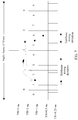
- FIG. 7 is an example of determining a subframe number according to Embodiment 3 of the present invention.
- TTIs corresponding to the five sub-bands are respectively 5 ms, 2 ms, 1 ms, 0.5 ms, and 0.25 ms.
- a subframe length of a sub-band with a 5-ms TTI and a subframe length of a sub-band with a 2-ms TTI are not in a multiple relationship.
- a frame with a 1-ms TTI is used as an example, and scheduling from a sub-band with a 1-ms TTI to another sub-band is considered.
- a sub-band with a moderate TTI for example, a sub-band with a 1-ms TTI
- a radio frame or referred to as a super frame
- Subframes in a super frame in each sub-band are numbered in sequence, and a start subframe number is 0.
- one frame in a sub-band with a 0.25-ms TTI, one frame (super frame) includes 40 subframes, and for a sub-band with a 5-ms TTI, one frame includes two subframes, and so on.
- a processing delay of the base station is 2 ms. It can be seen from FIG. 7 that if scheduling (for example, the message 4 in FIG. 3 or the message 2 in FIG. 5 ) is received at a second subframe (a subframe 1 with a 1-ms TTI) with a 1-ms TTI, scheduling (for example, sub-band synchronization in FIG. 3 or the message 3 in FIG. 5 ) on a target sub-band (with a 2-ms TTI) is in a subframe 2. If scheduling is received at a third subframe (a subframe 2 with a 1-ms TTI) with a 1-ms TTI, scheduling on a target sub-band can be performed only in a subframe 3.
- a subframe number may be directly obtained by means of calculation according to a formula provided in this embodiment of the present invention, or a table may be obtained according to the method provided in this embodiment of the present invention, and a subframe number is determined in a table lookup manner.
- determining a subframe number is equivalent to determining a start location of a subframe, and vice versa.
- the user terminal may perform transmission on multiple sub-bands at the same time.
- a conventional method is that the user terminal performs uplink scheduling request (English: Scheduling Request, SR for short) transmission by initiating a random access process.
- uplink scheduling request English: Scheduling Request, SR for short
- the method of performing uplink scheduling request transmission by initiating a random access process wastes system resources and causes a data transmission delay.
- an effective method is providing an independent MAC for each TTI (or for each sub-band), so that scheduling and transmission in a system are more efficient. Therefore, when an SR needs to be sent on a sub-band corresponding to a specific TTI, if a PUCCH resource is not configured on the sub-band (or a physical channel) corresponding to the current TTI, the SR may be sent on a resource on a sub-band corresponding to another TTI.
- FIG. 8 shows a scheduling request sending method according to Embodiment 4 of the present invention.
- an upper portion in FIG. 8 indicates an example of an independent MAC (or an independent MAC entity) supporting multiple TTIs.
- a sub-band corresponding to each TTI has a MAC entity (a TTI1 MAC, a TTI2 MAC, ..., and a TTIk MAC that are one-to-one corresponding to sub-bands).
- an SR may be sent by using a resource on a sub-band 2, and the SR may be sent together with data on the sub-band 2. If no data is sent on the sub-band 2, sending may be performed by using a PUCCH of the sub-band 2.
- FIG. 9 shows an SR transmission method according to Embodiment 4 of the present invention.
- the user terminal determines a sub-band (that is, a target sub-band) used for sending an SR, and sends the SR and a buffer status report (English: Buffer Status Report, BSR for short) to a MAC entity of the target sub-band.
- the target sub-band adds the SR to to-be-sent data, or sends the SR by using a PUCCH.
- the SR includes at least sub-band information of a source sub-band (the sub-band 1 in FIG. 8 ). If the SR is sent by using the PUCCH, the target sub-band instructs a physical layer to send the SR, and the SR includes the sub-band information of the source sub-band. If data is sent on the target sub-band, a base station is instructed, by adding a BSR (a MAC layer command) to the data, to allocate a resource to the source sub-band, and the BSR may further carry the sub-band information of the source sub-band.
- a BSR a MAC layer command
- a PDCCH on the target sub-band is monitored on the source sub-band (or a MAC entity of the source sub-band).
- the base station allocates a resource to the source sub-band.
- the base station sends the allocated resource to the source sub-band.
- a first method is directly sending an allocated UL grant resource on a PDCCH of the source sub-band. Because the source sub-band monitors the PDCCH, this method is implemented relatively directly.
- a second method is performing sending by using the target sub-band, and performing sending to the sending sub-band by using the target sub-band.
- the user terminal does not need to monitor the PDCCH (in FIG. 9 , the user terminal does not need to monitor the PDCCH on the target sub-band).
- a disadvantage of the second method is that the allocated UL grant resource needs to be sent on the target sub-band to the source sub-band, and this causes a delay.
- a PUCCH may be configured on only one sub-band in a system supporting multiple TTIs, and a PUCCH does not need to be configured on each sub-band.
- an embodiment of the present invention further provides a sub-band scheduling apparatus.
- the apparatus is used in a random access process and includes:
- Steps performed when the sending module 1001, the receiving module 1003, and the processing module 1002 implement corresponding functions have been described in detail in the method embodiments, and details are not described herein again.
- the source sub-band and the target sub-band are corresponding to different TTIs.
- the data is transmitted on the target sub-band according to the sub-band information of the target sub-band may include: after receiving the sub-band information of the target sub-band that is sent by the base station, a user terminal may preform scheduling from the source sub-band to the target sub-band according to the sub-band information of the target sub-band, adjust time synchronization according to the timing advance in the sub-band information, and transmit data on the uplink resource indicated by the sub-band information.
- the apparatus further includes: a synchronization module, configured to perform sub-band synchronization on the target sub-band.
- sub-band synchronization for example, sub-band synchronization, signature information, and subframe number determining, are similar to or corresponding to some technical features involved in the method embodiments of the present invention, and are not described again in this embodiment.
- an embodiment of the present invention further provides a sub-band scheduling apparatus.
- the apparatus is used in a random access process and includes: a physical transceiver module, multiple MAC processing modules, a MAC control module, and multiple data scheduling modules.
- a data scheduling unit is configured to schedule, according to information about a data attribute requirement of to-be-transmitted data, data that has same information about a data attribute requirement in a same MAC processing module.
- information about a data attribute requirement is corresponding to a TTI (or a TTI requirement). Therefore, data that has a same TTI requirement may be scheduled in a same MAC processing module.
- a MAC processing module is configured to perform MAC layer processing.
- the MAC layer processing includes parsing and encapsulating a random access message (for example, a message 1, a message 2, a message 3, or a message 4), receiving data of the data scheduling module, and the like. Specifically, the MAC layer processing is performed on data transmitted from the data scheduling module.
- different MAC processing modules are corresponding to different TTIs, that is, different MAC processing modules process data corresponding to different TTIs.
- the MAC control module is configured to implement message transmission between the multiple MAC processing modules. Specifically, during scheduling from a sub-band to another sub-band, a source MAC processing module needs to notify a target MAC processing module.
- the source MAC processing module sends, by using the MAC control module, timing adjustment information (that is, subframe delimitation information, and in this case, sub-band information needs to include the timing adjustment information) to the target MAC processing module according to sub-band information (the sub-band information meets the data attribute requirement of the to-be-transmitted data) received from a base station.
- the to-be-transmitted data may be transmitted by using the target MAC processing module.
- the physical transceiver module is configured to send data transmitted from the multiple MAC processing modules, and/or send received data that is obtained by means of physical layer processing to the multiple MAC processing modules.
- sub-band synchronization for example, sub-band synchronization, signature information, and subframe number determining, are similar to or corresponding to some technical features involved in the method embodiments of the present invention, and are not described again in this embodiment.
- an embodiment of the present invention further provides a sub-band scheduling apparatus.
- the apparatus is used in a random access process and includes:
- Steps performed when the sending module 1201, the receiving module 1203, and the processing module 1202 implement corresponding functions have been described in detail in the method embodiments, and details are not described herein again.
- the source sub-band and the target sub-band are corresponding to different TTIs.
- the processing module 1201 transmits data on the target sub-band according to the sub-band information of the target sub-band may include: after receiving the sub-band information of the target sub-band that is sent by the base station, the user terminal may preform scheduling from the source sub-band to the target sub-band according to the sub-band information of the target sub-band, adjust time synchronization according to the timing advance in the sub-band information, and transmit data on the uplink resource indicated by the sub-band information.
- sub-band synchronization for example, sub-band synchronization, signature information, and subframe number determining, are similar to or corresponding to some technical features involved in the method embodiments of the present invention, and are not described again in this embodiment.
- the sub-band scheduling apparatus provided in this embodiment of the present invention may be used in a user terminal, a network element node device, or a base station.
- An embodiment of the present invention further provides a processing device.
- the device includes: a processor 1301, a memory 1302, a transmitter 1303, a receiver 1305, and a bus 1304.
- the processor 1301, the memory 1302, the transmitter 1303, and the receiver 1305 are connected by using the bus 1304 for data transmission, and the memory 1302 is configured to store data processed by the processor 1301.
- the bus 1304 may be an industry standard architecture (Industry Standard Architecture, ISA for short) bus, a peripheral component interconnect (Peripheral Component, PCI for short) bus, an extended industry standard architecture (Extended Industry Standard Architecture, EISA for short) bus, or the like. This is not limited herein.
- the bus 1304 may be classified into an address bus, a data bus, a control bus, and the like. For ease of representation, only one bold line is used in FIG. 13 for representation, but it does not indicate that there is only one bus or one type of bus.
- the memory 1302 is configured to store data or executable program code, and the program code includes a computer operation instruction and may be specifically an operating system, an application program, or the like.
- the memory 1302 may include a high-speed RAM memory, and may further include a non-volatile memory (non-volatile memory), for example, at least one magnetic disk memory.
- the processor 1301 may be a central processing unit (Central Processing Unit, CPU for short), or an application-specific integrated circuit (Application Specific Integrated Circuit, ASIC for short), or one or more integrated circuits configured to implement this embodiment of the present invention.
- CPU Central Processing Unit
- ASIC Application Specific Integrated Circuit
- the transmitter 1303 and the receiver 1305 are configured to receive and send a message.
- the processor 1301 is configured to implement the sub-band scheduling method in the foregoing embodiments by executing the program code in the memory 1302.
- Some technical features involved, for example, sub-band synchronization, signature information, and subframe number determining, are similar to or corresponding to some technical features involved in the method embodiments of the present invention, and are not described again in this embodiment. A specific process is not described again.
- sequence numbers of the foregoing processes do not mean execution sequences in various embodiments of the present invention.
- the execution sequences of the processes should be determined according to functions and internal logic of the processes, and should not be construed as any limitation on the implementation processes of the embodiments of the present invention.
- the disclosed apparatus and method may be implemented in other manners.
- the described apparatus embodiment is merely an example.
- the unit division is merely logical function division and may be other division in actual implementation.
- a plurality of units or components may be combined or integrated into another system, or some features may be ignored or not performed.
- the displayed or discussed mutual couplings or direct couplings or communication connections may be implemented through some interfaces, indirect couplings or communication connections between the apparatuses or units, or electrical connections, mechanical connections, or connections in other forms.
- the units described as separate parts may or may not be physically separate, and parts displayed as units may or may not be physical units, may be located in one position, or may be distributed on a plurality of network units. Some or all of the units may be selected according to actual needs to achieve the objectives of the solutions of the embodiments of the present invention.
- functional units in the embodiments of the present invention may be integrated into one processing unit, or each of the units may exist alone physically, or two or more units are integrated into one unit.
- the integrated unit may be implemented in a form of hardware, or may be implemented in a form of a software functional unit. Specifically, the integrated unit may be implemented by using software in addition to necessary general-purpose hardware.
- the general-purpose hardware includes a general-purpose integrated circuit, a general-purpose CPU (English: Central Processing Unit), a general-purpose digital signal processor (English: Digital Signal Processor, DSP for short), a field programming gate array (English: Field Programming Gate Array, FPGA for short), a programmable logical device (English: Programmable Logical Device, PLD for short), a general-purpose memory, a general-purpose component, or the like.
- a general-purpose CPU English: Central Processing Unit
- a general-purpose digital signal processor English: Digital Signal Processor, DSP for short
- a field programming gate array English: Field Programming Gate Array, FPGA for short
- a programmable logical device English: Programmable Logical Device, PLD for short
- the integrated unit may be implemented by using an application specific integrated circuit (English: Application Specific Integrated Circuit, ASIC for short), a special-purpose CPU, a special-purpose memory, a special-purpose component, or the like.
- the integrated unit When the integrated unit is implemented in the form of a software functional unit and sold or used as an independent product, the integrated unit may be stored in a computer-readable storage medium. Based on such an understanding, the technical solutions of the present invention essentially, or the part contributing to the prior art, or all or some of the technical solutions may be implemented in the form of a software product.
- the software product is stored in a storage medium and includes several instructions for instructing a computer device (which may be a personal computer, a server, or a network device) to perform all or some of the steps of the methods described in the embodiments of the present invention.
- the foregoing storage medium includes: any medium that can store program code, such as a USB flash drive, a removable hard disk, a read-only memory (Read-Only Memory, ROM for short), a random access memory (Random Access Memory, RAM for short), a magnetic disk, or an optical disc.
- program code such as a USB flash drive, a removable hard disk, a read-only memory (Read-Only Memory, ROM for short), a random access memory (Random Access Memory, RAM for short), a magnetic disk, or an optical disc.
- software or an instruction may be transmitted by using a transmission medium.
- a transmission medium For example, if software is transmitted from a website, a server or another remote source by using a coaxial cable, an optical fiber/cable, a twisted pair, a digital subscriber line (English: Digital Subscriber Line, DSL for short) or wireless technologies (such as infrared ray, radio and microwave), the coaxial cable, optical fiber/cable, twisted pair, DSL or wireless technologies (such as infrared ray, radio and microwave) are included in definitions of a transmission medium.
Landscapes
- Engineering & Computer Science (AREA)
- Signal Processing (AREA)
- Computer Networks & Wireless Communication (AREA)
- Quality & Reliability (AREA)
- Mobile Radio Communication Systems (AREA)
Applications Claiming Priority (2)
| Application Number | Priority Date | Filing Date | Title |
|---|---|---|---|
| CN201510617843.0A CN106559874B (zh) | 2015-09-24 | 2015-09-24 | 一种子带调度方法、装置 |
| PCT/CN2016/100138 WO2017050296A1 (fr) | 2015-09-24 | 2016-09-26 | Procédé et dispositif de répartition de sous-bandes |
Publications (3)
| Publication Number | Publication Date |
|---|---|
| EP3346651A1 true EP3346651A1 (fr) | 2018-07-11 |
| EP3346651A4 EP3346651A4 (fr) | 2018-09-19 |
| EP3346651B1 EP3346651B1 (fr) | 2020-11-11 |
Family
ID=58385656
Family Applications (1)
| Application Number | Title | Priority Date | Filing Date |
|---|---|---|---|
| EP16848177.8A Active EP3346651B1 (fr) | 2015-09-24 | 2016-09-26 | Procédé et dispositif de répartition de sous-bandes |
Country Status (4)
| Country | Link |
|---|---|
| US (1) | US10582500B2 (fr) |
| EP (1) | EP3346651B1 (fr) |
| CN (1) | CN106559874B (fr) |
| WO (1) | WO2017050296A1 (fr) |
Families Citing this family (12)
| Publication number | Priority date | Publication date | Assignee | Title |
|---|---|---|---|---|
| WO2018227493A1 (fr) * | 2017-06-15 | 2018-12-20 | 华为技术有限公司 | Procédé d'accès aléatoire et dispositif associé |
| CN109246828B (zh) * | 2017-07-11 | 2023-06-27 | 普天信息技术有限公司 | 多子带系统中下行业务处理方法、基站及用户设备 |
| CN108476401B (zh) * | 2017-09-07 | 2021-02-26 | 北京小米移动软件有限公司 | 调度信令的检测方法、装置、用户设备和基站 |
| CN109587789B (zh) * | 2017-09-28 | 2021-09-24 | 维沃移动通信有限公司 | 随机接入方法、移动终端及网络设备 |
| WO2019157731A1 (fr) * | 2018-02-14 | 2019-08-22 | 华为技术有限公司 | Procédé d'accès aléatoire et appareil associé |
| WO2019191861A1 (fr) * | 2018-04-02 | 2019-10-10 | Qualcomm Incorporated | Transmission en parallèle de séquences de préambule avec des couches de données pour une meilleure détection des données |
| WO2020014897A1 (fr) * | 2018-07-18 | 2020-01-23 | Nokia Shanghai Bell Co., Ltd. | Indication de ressources dans une transmission fondée sur la contention |
| CN113348708A (zh) * | 2019-04-26 | 2021-09-03 | Oppo广东移动通信有限公司 | 一种选取传输资源方法以及选取传输数据的方法、终端 |
| CN113055066B (zh) | 2019-12-26 | 2022-11-04 | 大唐移动通信设备有限公司 | 一种通信方法和装置 |
| CN116171621B (zh) * | 2020-08-05 | 2025-05-16 | 苹果公司 | 用于利用用户装备在新无线电中动态调度的系统和方法 |
| US12581472B2 (en) | 2021-06-30 | 2026-03-17 | Beijing Xiaomi Mobile Software Co., Ltd. | Activation indication method and apparatus, frequency band activation method and apparatus, communication apparatus, and storage medium |
| CN120730427A (zh) * | 2024-03-29 | 2025-09-30 | 华为技术有限公司 | 通信方法及通信装置 |
Family Cites Families (15)
| Publication number | Priority date | Publication date | Assignee | Title |
|---|---|---|---|---|
| CN101212410B (zh) * | 2006-12-30 | 2010-08-25 | 大唐移动通信设备有限公司 | 一种实现下行资源调度的方法、系统及装置 |
| KR101260079B1 (ko) * | 2007-02-06 | 2013-05-02 | 엘지전자 주식회사 | 무선 통신 시스템의 랜덤 액세스 방법 |
| CN101567714A (zh) | 2008-04-24 | 2009-10-28 | 夏普株式会社 | 用于信息反馈的子带判决方法、基站、用户设备以及通信系统 |
| EP2399425A1 (fr) * | 2009-02-18 | 2011-12-28 | Nokia Siemens Networks OY | Contrôle des transmissions sur des porteuses composites |
| WO2010110522A1 (fr) * | 2009-03-22 | 2010-09-30 | Lg Electronics Inc. | Traitement d'une réponse d'accès aléatoire |
| JP5482794B2 (ja) | 2009-08-24 | 2014-05-07 | 日本電気株式会社 | 通信端末 |
| KR101785658B1 (ko) * | 2010-01-27 | 2017-10-16 | 엘지전자 주식회사 | 위치기반서비스를 위한 상향링크 신호 전송방법 및 사용자기기와, 상향링크 신호를 이용한 사용자기기의 위치측정방법 및 기지국 |
| JP5603288B2 (ja) * | 2011-04-26 | 2014-10-08 | 株式会社日立製作所 | 無線通信システム、無線通信方法および基地局装置 |
| US9642161B2 (en) * | 2011-05-11 | 2017-05-02 | Nokia Solutions And Networks Oy | Cross-scheduling for random access response |
| KR102401006B1 (ko) * | 2011-09-30 | 2022-05-24 | 인터디지탈 패튼 홀딩스, 인크 | 감소된 채널 대역폭을 사용하는 장치 통신 |
| US9131498B2 (en) | 2012-09-12 | 2015-09-08 | Futurewei Technologies, Inc. | System and method for adaptive transmission time interval (TTI) structure |
| CN109041018B (zh) * | 2012-10-29 | 2021-09-14 | 华为技术有限公司 | 一种资源确定方法、基站及用户设备 |
| US10420054B2 (en) * | 2014-03-28 | 2019-09-17 | Qualcomm Incorporated | Wireless communications in a system that supports a first subframe type having a first symbol duration and a second subframe type having a second symbol duration |
| EP3195508A1 (fr) * | 2014-09-08 | 2017-07-26 | Interdigital Patent Holdings, Inc. | Systèmes et procédés de commande avec différentes durées d'intervalles de temps de transmission (tti) |
| EP3286972B1 (fr) * | 2015-04-22 | 2019-05-15 | Intel IP Corporation | Demande de planification reposant sur un conflit à faible latence |
-
2015
- 2015-09-24 CN CN201510617843.0A patent/CN106559874B/zh active Active
-
2016
- 2016-09-26 WO PCT/CN2016/100138 patent/WO2017050296A1/fr not_active Ceased
- 2016-09-26 EP EP16848177.8A patent/EP3346651B1/fr active Active
-
2018
- 2018-03-21 US US15/928,069 patent/US10582500B2/en active Active
Also Published As
| Publication number | Publication date |
|---|---|
| WO2017050296A1 (fr) | 2017-03-30 |
| CN106559874B (zh) | 2020-12-15 |
| US10582500B2 (en) | 2020-03-03 |
| US20180213534A1 (en) | 2018-07-26 |
| CN106559874A (zh) | 2017-04-05 |
| EP3346651A4 (fr) | 2018-09-19 |
| EP3346651B1 (fr) | 2020-11-11 |
Similar Documents
| Publication | Publication Date | Title |
|---|---|---|
| US10582500B2 (en) | Sub-band scheduling method and apparatus | |
| US11089594B2 (en) | Resource allocation method, user equipment, and network device | |
| US10791575B2 (en) | Data transmission method, device and system | |
| CN106465401B (zh) | 在无线通信系统中发送具有低延迟的上行链路数据的方法和设备 | |
| EP3383081B1 (fr) | Procédé de transmission d'informations système, station de base et équipement utilisateur | |
| US10499436B2 (en) | Physical random access channel and random access response detection for user equipment | |
| US9900875B2 (en) | Method for configuring resource, method for receiving downlink control information, and terminal device | |
| CN114126073B (zh) | 用于等待时间减少的随机接入过程 | |
| EP3200495A1 (fr) | Procédé et appareil d'émission d'informations | |
| US10798716B2 (en) | Network device, terminal device, and resource allocation method | |
| EP3573402B1 (fr) | Procédé de communication et terminal | |
| EP3209076B1 (fr) | Procédé et dispositif de transmission de données | |
| EP2680651A1 (fr) | Procédé, dispositif de station de base, dispositif de terminal et système de communication pour une attribution de ressources de canal | |
| EP3468289B1 (fr) | Procédé de transmission de signal, et appareil | |
| US10506580B2 (en) | Uplink data transmission method and device | |
| CN113207179A (zh) | 数据传输方法和装置 | |
| CN114051257B (zh) | 传输信号的方法和装置 | |
| EP3496351A1 (fr) | Procédé et dispositif de transmission de signal pilote | |
| CN110366261A (zh) | 一种连接态终端随机接入方法和装置 | |
| CN106954278B (zh) | 确定随机接入无线网络临时标识的方法、用户设备和基站 | |
| CN103782631A (zh) | 基站以及通信控制方法 |
Legal Events
| Date | Code | Title | Description |
|---|---|---|---|
| STAA | Information on the status of an ep patent application or granted ep patent |
Free format text: STATUS: THE INTERNATIONAL PUBLICATION HAS BEEN MADE |
|
| PUAI | Public reference made under article 153(3) epc to a published international application that has entered the european phase |
Free format text: ORIGINAL CODE: 0009012 |
|
| STAA | Information on the status of an ep patent application or granted ep patent |
Free format text: STATUS: REQUEST FOR EXAMINATION WAS MADE |
|
| 17P | Request for examination filed |
Effective date: 20180403 |
|
| AK | Designated contracting states |
Kind code of ref document: A1 Designated state(s): AL AT BE BG CH CY CZ DE DK EE ES FI FR GB GR HR HU IE IS IT LI LT LU LV MC MK MT NL NO PL PT RO RS SE SI SK SM TR |
|
| AX | Request for extension of the european patent |
Extension state: BA ME |
|
| A4 | Supplementary search report drawn up and despatched |
Effective date: 20180822 |
|
| RIC1 | Information provided on ipc code assigned before grant |
Ipc: H04L 5/00 20060101AFI20180816BHEP Ipc: H04W 72/12 20090101ALI20180816BHEP Ipc: H04W 56/00 20090101ALI20180816BHEP Ipc: H04L 27/26 20060101ALI20180816BHEP Ipc: H04W 72/04 20090101ALI20180816BHEP |
|
| DAV | Request for validation of the european patent (deleted) | ||
| DAX | Request for extension of the european patent (deleted) | ||
| STAA | Information on the status of an ep patent application or granted ep patent |
Free format text: STATUS: EXAMINATION IS IN PROGRESS |
|
| 17Q | First examination report despatched |
Effective date: 20191007 |
|
| REG | Reference to a national code |
Ref country code: DE Ref legal event code: R079 Ref document number: 602016047833 Country of ref document: DE Free format text: PREVIOUS MAIN CLASS: H04L0012700000 Ipc: H04L0005000000 |
|
| GRAP | Despatch of communication of intention to grant a patent |
Free format text: ORIGINAL CODE: EPIDOSNIGR1 |
|
| STAA | Information on the status of an ep patent application or granted ep patent |
Free format text: STATUS: GRANT OF PATENT IS INTENDED |
|
| RIC1 | Information provided on ipc code assigned before grant |
Ipc: H04W 74/08 20090101ALN20200513BHEP Ipc: H04W 72/12 20090101ALI20200513BHEP Ipc: H04L 5/00 20060101AFI20200513BHEP Ipc: H04L 27/26 20060101ALN20200513BHEP Ipc: H04W 56/00 20090101ALI20200513BHEP |
|
| INTG | Intention to grant announced |
Effective date: 20200615 |
|
| GRAS | Grant fee paid |
Free format text: ORIGINAL CODE: EPIDOSNIGR3 |
|
| GRAA | (expected) grant |
Free format text: ORIGINAL CODE: 0009210 |
|
| STAA | Information on the status of an ep patent application or granted ep patent |
Free format text: STATUS: THE PATENT HAS BEEN GRANTED |
|
| AK | Designated contracting states |
Kind code of ref document: B1 Designated state(s): AL AT BE BG CH CY CZ DE DK EE ES FI FR GB GR HR HU IE IS IT LI LT LU LV MC MK MT NL NO PL PT RO RS SE SI SK SM TR |
|
| REG | Reference to a national code |
Ref country code: GB Ref legal event code: FG4D |
|
| REG | Reference to a national code |
Ref country code: CH Ref legal event code: EP |
|
| REG | Reference to a national code |
Ref country code: AT Ref legal event code: REF Ref document number: 1334475 Country of ref document: AT Kind code of ref document: T Effective date: 20201115 |
|
| REG | Reference to a national code |
Ref country code: DE Ref legal event code: R096 Ref document number: 602016047833 Country of ref document: DE |
|
| REG | Reference to a national code |
Ref country code: IE Ref legal event code: FG4D |
|
| REG | Reference to a national code |
Ref country code: NL Ref legal event code: MP Effective date: 20201111 |
|
| REG | Reference to a national code |
Ref country code: AT Ref legal event code: MK05 Ref document number: 1334475 Country of ref document: AT Kind code of ref document: T Effective date: 20201111 |
|
| PG25 | Lapsed in a contracting state [announced via postgrant information from national office to epo] |
Ref country code: GR Free format text: LAPSE BECAUSE OF FAILURE TO SUBMIT A TRANSLATION OF THE DESCRIPTION OR TO PAY THE FEE WITHIN THE PRESCRIBED TIME-LIMIT Effective date: 20210212 Ref country code: FI Free format text: LAPSE BECAUSE OF FAILURE TO SUBMIT A TRANSLATION OF THE DESCRIPTION OR TO PAY THE FEE WITHIN THE PRESCRIBED TIME-LIMIT Effective date: 20201111 Ref country code: NO Free format text: LAPSE BECAUSE OF FAILURE TO SUBMIT A TRANSLATION OF THE DESCRIPTION OR TO PAY THE FEE WITHIN THE PRESCRIBED TIME-LIMIT Effective date: 20210211 Ref country code: RS Free format text: LAPSE BECAUSE OF FAILURE TO SUBMIT A TRANSLATION OF THE DESCRIPTION OR TO PAY THE FEE WITHIN THE PRESCRIBED TIME-LIMIT Effective date: 20201111 Ref country code: PT Free format text: LAPSE BECAUSE OF FAILURE TO SUBMIT A TRANSLATION OF THE DESCRIPTION OR TO PAY THE FEE WITHIN THE PRESCRIBED TIME-LIMIT Effective date: 20210311 |
|
| PG25 | Lapsed in a contracting state [announced via postgrant information from national office to epo] |
Ref country code: SE Free format text: LAPSE BECAUSE OF FAILURE TO SUBMIT A TRANSLATION OF THE DESCRIPTION OR TO PAY THE FEE WITHIN THE PRESCRIBED TIME-LIMIT Effective date: 20201111 Ref country code: PL Free format text: LAPSE BECAUSE OF FAILURE TO SUBMIT A TRANSLATION OF THE DESCRIPTION OR TO PAY THE FEE WITHIN THE PRESCRIBED TIME-LIMIT Effective date: 20201111 Ref country code: LV Free format text: LAPSE BECAUSE OF FAILURE TO SUBMIT A TRANSLATION OF THE DESCRIPTION OR TO PAY THE FEE WITHIN THE PRESCRIBED TIME-LIMIT Effective date: 20201111 Ref country code: IS Free format text: LAPSE BECAUSE OF FAILURE TO SUBMIT A TRANSLATION OF THE DESCRIPTION OR TO PAY THE FEE WITHIN THE PRESCRIBED TIME-LIMIT Effective date: 20210311 Ref country code: BG Free format text: LAPSE BECAUSE OF FAILURE TO SUBMIT A TRANSLATION OF THE DESCRIPTION OR TO PAY THE FEE WITHIN THE PRESCRIBED TIME-LIMIT Effective date: 20210211 Ref country code: AT Free format text: LAPSE BECAUSE OF FAILURE TO SUBMIT A TRANSLATION OF THE DESCRIPTION OR TO PAY THE FEE WITHIN THE PRESCRIBED TIME-LIMIT Effective date: 20201111 |
|
| REG | Reference to a national code |
Ref country code: LT Ref legal event code: MG9D |
|
| PG25 | Lapsed in a contracting state [announced via postgrant information from national office to epo] |
Ref country code: HR Free format text: LAPSE BECAUSE OF FAILURE TO SUBMIT A TRANSLATION OF THE DESCRIPTION OR TO PAY THE FEE WITHIN THE PRESCRIBED TIME-LIMIT Effective date: 20201111 |
|
| PG25 | Lapsed in a contracting state [announced via postgrant information from national office to epo] |
Ref country code: RO Free format text: LAPSE BECAUSE OF FAILURE TO SUBMIT A TRANSLATION OF THE DESCRIPTION OR TO PAY THE FEE WITHIN THE PRESCRIBED TIME-LIMIT Effective date: 20201111 Ref country code: SK Free format text: LAPSE BECAUSE OF FAILURE TO SUBMIT A TRANSLATION OF THE DESCRIPTION OR TO PAY THE FEE WITHIN THE PRESCRIBED TIME-LIMIT Effective date: 20201111 Ref country code: EE Free format text: LAPSE BECAUSE OF FAILURE TO SUBMIT A TRANSLATION OF THE DESCRIPTION OR TO PAY THE FEE WITHIN THE PRESCRIBED TIME-LIMIT Effective date: 20201111 Ref country code: CZ Free format text: LAPSE BECAUSE OF FAILURE TO SUBMIT A TRANSLATION OF THE DESCRIPTION OR TO PAY THE FEE WITHIN THE PRESCRIBED TIME-LIMIT Effective date: 20201111 Ref country code: SM Free format text: LAPSE BECAUSE OF FAILURE TO SUBMIT A TRANSLATION OF THE DESCRIPTION OR TO PAY THE FEE WITHIN THE PRESCRIBED TIME-LIMIT Effective date: 20201111 Ref country code: LT Free format text: LAPSE BECAUSE OF FAILURE TO SUBMIT A TRANSLATION OF THE DESCRIPTION OR TO PAY THE FEE WITHIN THE PRESCRIBED TIME-LIMIT Effective date: 20201111 |
|
| REG | Reference to a national code |
Ref country code: DE Ref legal event code: R097 Ref document number: 602016047833 Country of ref document: DE |
|
| PG25 | Lapsed in a contracting state [announced via postgrant information from national office to epo] |
Ref country code: DK Free format text: LAPSE BECAUSE OF FAILURE TO SUBMIT A TRANSLATION OF THE DESCRIPTION OR TO PAY THE FEE WITHIN THE PRESCRIBED TIME-LIMIT Effective date: 20201111 |
|
| PLBE | No opposition filed within time limit |
Free format text: ORIGINAL CODE: 0009261 |
|
| STAA | Information on the status of an ep patent application or granted ep patent |
Free format text: STATUS: NO OPPOSITION FILED WITHIN TIME LIMIT |
|
| 26N | No opposition filed |
Effective date: 20210812 |
|
| PG25 | Lapsed in a contracting state [announced via postgrant information from national office to epo] |
Ref country code: IT Free format text: LAPSE BECAUSE OF FAILURE TO SUBMIT A TRANSLATION OF THE DESCRIPTION OR TO PAY THE FEE WITHIN THE PRESCRIBED TIME-LIMIT Effective date: 20201111 Ref country code: AL Free format text: LAPSE BECAUSE OF FAILURE TO SUBMIT A TRANSLATION OF THE DESCRIPTION OR TO PAY THE FEE WITHIN THE PRESCRIBED TIME-LIMIT Effective date: 20201111 Ref country code: NL Free format text: LAPSE BECAUSE OF FAILURE TO SUBMIT A TRANSLATION OF THE DESCRIPTION OR TO PAY THE FEE WITHIN THE PRESCRIBED TIME-LIMIT Effective date: 20201111 |
|
| PG25 | Lapsed in a contracting state [announced via postgrant information from national office to epo] |
Ref country code: SI Free format text: LAPSE BECAUSE OF FAILURE TO SUBMIT A TRANSLATION OF THE DESCRIPTION OR TO PAY THE FEE WITHIN THE PRESCRIBED TIME-LIMIT Effective date: 20201111 |
|
| PG25 | Lapsed in a contracting state [announced via postgrant information from national office to epo] |
Ref country code: ES Free format text: LAPSE BECAUSE OF FAILURE TO SUBMIT A TRANSLATION OF THE DESCRIPTION OR TO PAY THE FEE WITHIN THE PRESCRIBED TIME-LIMIT Effective date: 20201111 |
|
| REG | Reference to a national code |
Ref country code: DE Ref legal event code: R119 Ref document number: 602016047833 Country of ref document: DE |
|
| REG | Reference to a national code |
Ref country code: CH Ref legal event code: PL |
|
| REG | Reference to a national code |
Ref country code: BE Ref legal event code: MM Effective date: 20210930 |
|
| PG25 | Lapsed in a contracting state [announced via postgrant information from national office to epo] |
Ref country code: IS Free format text: LAPSE BECAUSE OF FAILURE TO SUBMIT A TRANSLATION OF THE DESCRIPTION OR TO PAY THE FEE WITHIN THE PRESCRIBED TIME-LIMIT Effective date: 20210311 Ref country code: MC Free format text: LAPSE BECAUSE OF FAILURE TO SUBMIT A TRANSLATION OF THE DESCRIPTION OR TO PAY THE FEE WITHIN THE PRESCRIBED TIME-LIMIT Effective date: 20201111 |
|
| PG25 | Lapsed in a contracting state [announced via postgrant information from national office to epo] |
Ref country code: LU Free format text: LAPSE BECAUSE OF NON-PAYMENT OF DUE FEES Effective date: 20210926 Ref country code: IE Free format text: LAPSE BECAUSE OF NON-PAYMENT OF DUE FEES Effective date: 20210926 Ref country code: FR Free format text: LAPSE BECAUSE OF NON-PAYMENT OF DUE FEES Effective date: 20210930 Ref country code: DE Free format text: LAPSE BECAUSE OF NON-PAYMENT OF DUE FEES Effective date: 20220401 Ref country code: BE Free format text: LAPSE BECAUSE OF NON-PAYMENT OF DUE FEES Effective date: 20210930 |
|
| PG25 | Lapsed in a contracting state [announced via postgrant information from national office to epo] |
Ref country code: LI Free format text: LAPSE BECAUSE OF NON-PAYMENT OF DUE FEES Effective date: 20210930 Ref country code: CH Free format text: LAPSE BECAUSE OF NON-PAYMENT OF DUE FEES Effective date: 20210930 |
|
| PG25 | Lapsed in a contracting state [announced via postgrant information from national office to epo] |
Ref country code: HU Free format text: LAPSE BECAUSE OF FAILURE TO SUBMIT A TRANSLATION OF THE DESCRIPTION OR TO PAY THE FEE WITHIN THE PRESCRIBED TIME-LIMIT; INVALID AB INITIO Effective date: 20160926 |
|
| PG25 | Lapsed in a contracting state [announced via postgrant information from national office to epo] |
Ref country code: CY Free format text: LAPSE BECAUSE OF FAILURE TO SUBMIT A TRANSLATION OF THE DESCRIPTION OR TO PAY THE FEE WITHIN THE PRESCRIBED TIME-LIMIT Effective date: 20201111 |
|
| PG25 | Lapsed in a contracting state [announced via postgrant information from national office to epo] |
Ref country code: MK Free format text: LAPSE BECAUSE OF FAILURE TO SUBMIT A TRANSLATION OF THE DESCRIPTION OR TO PAY THE FEE WITHIN THE PRESCRIBED TIME-LIMIT Effective date: 20201111 |
|
| PG25 | Lapsed in a contracting state [announced via postgrant information from national office to epo] |
Ref country code: TR Free format text: LAPSE BECAUSE OF FAILURE TO SUBMIT A TRANSLATION OF THE DESCRIPTION OR TO PAY THE FEE WITHIN THE PRESCRIBED TIME-LIMIT Effective date: 20201111 |
|
| PG25 | Lapsed in a contracting state [announced via postgrant information from national office to epo] |
Ref country code: MT Free format text: LAPSE BECAUSE OF FAILURE TO SUBMIT A TRANSLATION OF THE DESCRIPTION OR TO PAY THE FEE WITHIN THE PRESCRIBED TIME-LIMIT Effective date: 20201111 |
|
| PGFP | Annual fee paid to national office [announced via postgrant information from national office to epo] |
Ref country code: GB Payment date: 20250807 Year of fee payment: 10 |