EP3346737A1 - Dispositif de communication sans fil vestimentaire et procédé de réglage de groupe de communication l'utilisant - Google Patents
Dispositif de communication sans fil vestimentaire et procédé de réglage de groupe de communication l'utilisant Download PDFInfo
- Publication number
- EP3346737A1 EP3346737A1 EP17150903.7A EP17150903A EP3346737A1 EP 3346737 A1 EP3346737 A1 EP 3346737A1 EP 17150903 A EP17150903 A EP 17150903A EP 3346737 A1 EP3346737 A1 EP 3346737A1
- Authority
- EP
- European Patent Office
- Prior art keywords
- wireless communication
- communication device
- communication group
- setting information
- signal
- Prior art date
- Legal status (The legal status is an assumption and is not a legal conclusion. Google has not performed a legal analysis and makes no representation as to the accuracy of the status listed.)
- Granted
Links
Images









Classifications
-
- H—ELECTRICITY
- H04—ELECTRIC COMMUNICATION TECHNIQUE
- H04W—WIRELESS COMMUNICATION NETWORKS
- H04W4/00—Services specially adapted for wireless communication networks; Facilities therefor
- H04W4/06—Selective distribution of broadcast services, e.g. multimedia broadcast multicast service [MBMS]; Services to user groups; One-way selective calling services
- H04W4/08—User group management
Definitions
- the present invention relates to a wearable wireless communication device and a method of setting a communication group using the same, and more particularly to, a wearable wireless communication device capable of performing transmission and reception at the same time using a time-sharing method through, for example, a full duplex function and including an ergonomically designed case configured to be easily worn and having a light weight to make a user feel comfortable during a long time use and a communication group setting method using the same.
- a radio is a machine used for radiotelegraph or radiotelephone.
- a radio transceiver When a radio transceiver is used, it is possible to perform mutual communication while a base station or a relay station is unnecessary and there is no call charge.
- a radio is used in various fields. For example, in the fields of an industrial field, a factory, the military, climbing and leisure and sport fields in addition to the police, portable radios, daily radios, vehicular radios, and trunked radio system (TRS) radios are used.
- TRS trunked radio system
- a radio regenerates a received sound by converting and outputting a signal received through an antenna through an external speaker and transmits a transmitted sound input through an external microphone to an opponent.
- radios use a simplex or half duplex communication method and wearable type radios that have been recently developed much more use the same.
- An aspect of the present invention provides a wearable wireless communication device capable of performing transmission and reception at the same time using a time sharing method through a full duplex function and a wireless communication method of using the same.
- Another aspect of the present invention provides a wearable wireless communication device that clearly performs communication among the wearable wireless communication devices in the corresponding communication group without noise and miscommunication as less as possible because it is possible to allow communication to be performed only among wearable wireless communication devices in a communication group set by a division function using a code combination and a wireless communication method using the same.
- Another aspect of the present invention provides a wearable wireless communication device capable of automatically sending out a voice signal input to a receiver through a radio frequency (RF) transceiver and an antenna of the wearable wireless communication device even without additional operation of a user for inputting a voice through a push to talk (PTT) button and the like and a wireless communication method using the same.
- RF radio frequency
- Another aspect of the present invention provides a wearable wireless communication device that is easily worn due to an ergonomically designed case applied thereto and allows a user to feel comfortable without inconvenience even for a long time use and a wireless communication method using the same.
- Another aspect of the present invention provides a wearable wireless communication device that may remotely control transmission of another wearable wireless communication device and may form a master-slave relationship between a plurality of wearable wireless communication devices to more efficiently perform voice communication between the wearable wireless communication devices between which the master-slave relationship is formed as described above and a wireless communication method using the same.
- Another aspect of the present invention provides a wearable wireless communication device that may set a communication group with other wireless communication devices within a limited range by converting and sending out communication group setting information into a dual tone multi-frequency (DTMF) signal or by transmitting communication group setting information including a certain received signal strength indicator (RSSI) reference value and a communication group setting method using the same.
- DTMF dual tone multi-frequency
- RSSI received signal strength indicator
- a wearable wireless communication device including a receiver to which an analog voice signal is input, a first amplifier configured to amplify the analog voice signal input through the receiver, an analog/digital (A/D) converter configured to convert the amplified analog voice signal output from the first amplifier into a digital voice signal, a controller configured to receive and output the digital voice signal output from the A/D converter and to output a digital voice signal received through an antenna and input, an RF transceiver configured to control the input of the signal received at the controller through the antenna and transmission of the signal output from the controller through the antenna, a digital/analog (D/A) converter configured to convert the digital voice signal output from the controller into an analog voice signal, a second amplifier configured to amplify the analog voice signal output from the D/A converter, and a voice output portion configured to transmit the analog voice signal output from the second amplifier.
- the controller transmits communication group setting information to other wireless communication devices within a limited range to set a communication group with the other wireless communication
- the controller may convert the communication group setting information into a DTMF signal and may send out the DTMF signal through the voice output portion.
- the controller may obtain the communication group setting information by decoding the input DTMF signal and.
- the DTMF signal may have a frequency component of a 4 ⁇ 4 matrix.
- the controller may transmit the communication group setting information including a certain RSSI reference value through the antenna.
- the controller may extract the RSSI reference value from the received communication group setting information when the communication group setting information is received through the antenna and may check the received communication group setting information when a measured RSSI value is the extracted RSSI reference value or more.
- the communication group setting information may include a control instruction (INST) packet, and the RSSI reference value may be included in a Reserve1 or Reserve2 area of the control INST packet.
- INST control instruction
- the communication group setting information may include an ID, a paring code, a master, a slave, and a control INST of a wireless communication device to be included in the communication group.
- the controller may amplify a signal received through the antenna and may transmit the signal through the antenna to allow the wearable wireless communication device to operate as a repeater or relay function.
- the controller may transmit a signal received from another wireless communication device to a VoIP apparatus and may transmit a signal received form the VoIP apparatus to the other wireless communication device to allow the wearable wireless communication device to operate a donor radio.
- a wireless communication method using a wearable wireless communication device including transmitting, by a wearable wireless communication device intended to set a communication group, communication group setting information to other wireless communication devices in a limited range to allow the wearable wireless communication device to set the communication group with the wireless communication devices and setting the communication group by allowing the other wireless communication devices to receive and check the communication group setting information.
- the transmitting of the communication group setting information may include converting the communication group setting information into a DTMF signal and sending out the DTMF signal through a speaker.
- the setting of the communication group may include receiving the DTMF signal through a microphone and obtaining the communication group setting information by decoding the DTMF signal.
- the transmitting of the communication group setting information may include transmitting the communication group setting information including a certain RSSI reference value through an antenna.
- the setting of the communication group may include receiving the communication group setting information through the antenna and extracting the RSSI reference value from the received communication group setting information and checking the received communication group setting information when a measured RSSI value is the extracted RSSI reference value or more.
- portion includes an element, unless defined otherwise, it means that the portion does not exclude other elements but may further include other elements.
- portion means units each configured to perform at least one function or operation and may be embodied as hardware, software, or a combination of hardware and software.
- FIGS. 1 to 18 a wearable wireless communication device and a wireless communication method using the same according to one embodiment of the present invention will be described.
- FIG. 1 is a block diagram illustrating a configuration of the wearable wireless communication device according to one embodiment of the present invention.
- a wearable wireless communication device 100 includes a receiver 110, a first amplifier 120, an analog/digital (A/D) converter 130, a controller 140, a radio frequency (RF) transceiver 150, a digital/analog (D/A) converter 160, a second amplifier 170, a voice output portion 180, and an antenna 220.
- the wearable wireless communication device 100 may further include a comparator 190, an input portion 200, a display portion 210, and a case (not shown, refer to FIGS. 8 and 9 ).
- the receiver 110 is a portion to which an analog voice signal is input. That is, a user of the wearable wireless communication device 100 inputs a voice through the receiver 110. Also, the receiver 110 may be a general microphone.
- the first amplifier 120 amplifies the analog voice signal input through the receiver 110.
- the A/D converter 130 converts the amplified analog voice signal output from the first amplifier 120 into a digital voice signal.
- the controller 140 receives the digital voice signal output from the A/D converter 130 and outputs the digital voice signal to the RF transceiver 150. Also, the controller 140 outputs a digital voice signal received through the antenna 220 and input through the RF transceiver 150.
- the digital voice signal received through the antenna 220 corresponds to a digital voice signal transmitted from another wearable wireless communication device or transmitted from another device.
- controller 140 enables full duplex communication with another wireless communication through controlling of a time-sharing function of the antenna 220.
- the controller 140 may set a group of other wearable wireless communication devices communicable with a sharing function due to a code combination and may enable communication among wearable wireless communication devices in the set group through this.
- the RF transceiver 150 controls the input of signals received at the controller 140 through the antenna 220 and the transmission of signals output from the controller 140.
- the D/A converter 160 converts a digital voice signal output from the controller 140 into an analog voice signal.
- the second amplifier 170 amplifies the analog voice signal output from the D/A converter 160.
- the voice output portion 180 sends out an analog voice signal output from the second amplifier 170. That is, the user of the wearable wireless communication device 100 listens to a voice of a user of another wearable wireless communication device or another device transmitted therefrom through the voice output portion 180.
- the voice output portion 180 described above may be a general speaker.
- the comparator 190 is connected to an output terminal of the first amplifier 120 in parallel with the A/D converter 130 and distinguishes whether voice data is present in an amplified analog voice signal output from the first amplifier 120. Also, the controller 140 is connected in parallel with the A/D converter 130 and the comparator 190 and automatically outputs a digital voice signal input from the A/D converter 130 to the RF transceiver 150 according to a signal input from the comparator 190.
- the wearable wireless communication device 100 determines whether voice data is present in an output signal of the first amplifier 120 through an output signal of the comparator 190 and automatically outputs the corresponding voice data to the RF transceiver 150 to send out through the antenna 220 when the voice data is present, the user of the wearable wireless communication device 100 may automatically send out a voice input to the receiver 110 without operating a push-to-talk (PTT) button and the like.
- PTT push-to-talk
- the input portion 200 performs a signal input function including a PTT signal at the controller 140.
- the input portion 200 described above may include various buttons including a PTT button.
- the display portion 210 is connected to the controller 140 and displays a system setting value and state information of the wearable wireless communication device 100 on a screen. That is, the user of the wearable wireless communication device 100 may perform various settings on the corresponding wearable wireless communication device 100 through the display portion 210 and may visually check a present setting state and an operation state of the wearable wireless communication device 100 that is being used.
- controller 140 may divide a signal output to the RF transceiver 150 into a basic packet and a control instruction (INST) packet to output.
- INHT control instruction
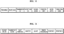
- FIGS. 2 and 3 illustrate the basic packet and the control INST packet of the wearable wireless communication device according to one embodiment of the present invention.
- the basic packet is a basic digital transmission/reception frame including voice data
- the control INST packet is a frame including a control command set necessary in addition to transmitting of voice data transmission and may be transmitted separately from and consecutively to the basic packet whenever a command occurs.
- the basic packet may include a preamble, a start code, a transmission ID, a reception ID, a pairing code that functions as a password, a control INST, voice data, and a completion code and the control INST packet may include a packet delay, the number of slots, a slot ranking, a master, a slave, remote transmission, Reserve1, and Reserve2.
- the pairing code when paring codes coincide, it is possible to connect a call with another wearable wireless communication device.
- the master and the slave of the control INST packet include information on a master for distributing a control command set and a slave for receiving the control command set distributed through the master and also may include information in which the master transfers authority to distribute the control command set to a particular slave.
- a master-slave relationship may be formed between two or more wearable wireless communication devices.
- a master function is transferred to a particular slave wearable wireless communication device through a particular wearable wireless communication device configured to function as a master in such a way that communication between wearable wireless communication devices may be performed based thereon.
- remote transmission of the control INST packet may include information on transmission control and exclusive reception with respect to a particular slave of a master.
- a maximum time slot Tn of the basic packet may be a packet delay T/number n of slots (here, the number n of slots is an integer smaller than ⁇ maximum transmission speed/general voice sampling speed (20 kbps)> and is extendable through data compression when necessary).
- the number of slots and the slot ranking of the control INST packet may display the number n of slots and the slot ranking N to allow a new communicator to enter the number of slots substituting for a last ranking of N communicator and to communicate when communicators in the communication group exceed the number n of slots (here, the communicator that exceeds the number of slots in the group is also able to always perform reception from all communicators therein).
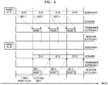
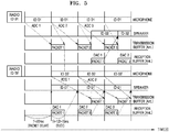
- FIGS. 4 to 6 are communication timing diagrams of the wearable wireless communication device according to one embodiment of the present invention.
- FIG. 4 illustrates an example of transmitting a packet from a wearable wireless communication device whose ID is 01 to another wearable wireless communication device whose ID is 02 through a time-sharing method.
- FIG. 5 illustrates a process of performing communication through 1:1 type full duplex and time-sharing packet transmission between the wearable wireless communication device whose ID is 01 and the other wearable wireless communication device whose ID is 02.
- FIG. 6 illustrates a process of performing communication through 1:1 type full duplex and time-sharing packet transmission among wearable wireless communication devices whose IDs are 01 to n.
- the controller 140 may remain in a sleep mode for a preset time in a standby state for receiving signals from other wearable wireless communication devices through the antenna 220 or a standby state for receiving an analog voice signal through the receiver 110 and then may operate in an auto polling mode for a preset time to reduce power consumption while standing by reception by repeating conversions of the sleep mode and the auto polling mode.
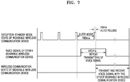
- FIG. 7 is a view illustrating an example of a signal standby state in the wearable wireless communication device according to one embodiment of the present invention.
- a reception-standby mode of the wearable wireless communication device 100 includes a sleep mode section and an auto polling section. That is, the reception-standby mode of the wearable wireless communication device 100 has one period including the sleep mode section and the auto polling section and the one period of the sleep mode section and the auto polling section is repeatedly performed until a voice signal from another wearable wireless communication device is received.
- a setting time of maintaining a sleep mode of the reception-standby mode is set to be 180 ms and a setting time of maintaining auto polling is set to be 20 ms.
- one period is total 4,000 ms and the corresponding period is repeatedly performed until a voice signal is received from other wearable wireless communication device.
- the other wearable wireless communication device may repeatedly transmit a voice signal for 220 ms that is a preset setting time. Accordingly, since a time of 20 ms in which the auto polling is maintained during the reception-standby mode of the wearable wireless communication device 100 overlaps within a range of 220 ms that is a setting time for receiving a voice signal transmitted from other wearable wireless communication device, the wearable wireless communication device 100 receives the voice signal transmitted from the other wearable wireless communication device and then may transmit and receive voice signals with the other wearable wireless communication device 100.
- the wearable wireless communication device 100 may greatly reduce power consumption in a reception-standby state through the reception-standby mode using the auto polling method than an existing reception-standby mode of always operating in an active state.
- the controller 140 may transmit communication group setting information to other wireless communication devices to allow the wearable wireless communication device 100 to set a communication group with other wireless communication devices within a communication range or a limited range.
- the controller 140 may convert the communication group setting information into a dual tone multi-frequency (DTMF) signal and send out the DTMF signal through the voice output portion 180 or may input a certain received signal strength indicator (RSSI) value into the communication group setting information to transmit to the antenna 220.
- DTMF dual tone multi-frequency
- RSSI received signal strength indicator
- the wireless wearable communication device 100 may further include a case that is a matrix for installing the receiver 110, the first amplifier 120, the A/D converter 130, the controller 140, the RF transceiver 150, the D/A converter 160, the second amplifier 170, and the voice output portion 180.
- FIG. 8 is a perspective view illustrating an example of a speaker type wireless wearable communication device according to one embodiment of the present invention.
- a case 230 has a structure for exposing the microphone 110, the speaker 180, an earphone port and the like and includes a strap connector and a detachable clip to be attached to user's clothing.
- the present invention is not limited thereto.
- FIG. 9 is a perspective view illustrating an example of an earphone type wireless wearable communication device according to one embodiment of the present invention.
- a case 330 has a structure for exposing an earphone port without an external speaker and a microphone.
- the present invention is not limited thereto.
- the wearable wireless communication device 100 may perform transmission and reception at the same time using the time sharing method and the like through the full duplex function of the controller 140.
- the communication among the wearable wireless communication devices in the corresponding communication group may be performed in a clear state in which noise and miscommunication are maximally prevented.
- power consumption in the reception-standby state may be greatly reduced using a function of the controller 140 in which one period of the reception-standby state that includes a sleep mode and an auto polling mode is repeated.
- the user of the wearable wireless communication device 100 may automatically send out a voice signal input to the receiver 110 through the RF transceiver 150 of the wearable wireless communication device 100 and the antenna 220 without additionally operating a PTT button and the like for inputting a voice.
- the wearable wireless communication device 100 is easily wearable according to applying of the case 230 or 330 that is ergonomically designed, and there is no additional inconvenience due to a light weight of the case 230 or 330 even when the wearable wireless communication device 100 is used for a long time.
- the wearable wireless communication device 100 described above with reference to FIGS. 1 to 9 is an example of a wearable wireless communication device used in the wireless communication method according to one embodiment of the present invention. Accordingly, in the following description, corresponding components of the wearable wireless communication device will be referred to as the like reference numerals as those of the wearable wireless communication device described above with reference to FIGS. 1 to 9 .
- FIG. 10 is a flowchart illustrating a signal transmission process in a wireless communication method of the wireless wearable communication device according to one embodiment of the present invention.
- the receiver 110 stands by the input of an analog voice signal.
- the controller 140 determines whether a PTT signal is input through the input portion 200 or whether a voice data existence signal is input through the comparator 190.
- the controller 140 when it is determined that there is the input of the PTT signal through the input portion 200 or there is the input of the voice data existence signal through the comparator 190, the controller 140 outputs an ID and a paring code of the wearable wireless communication device 100 to the RF transceiver 150.
- the controller 140 outputs a digital voice signal input through the receiver 110 and then converted at the A/D converter 130 to the RF transceiver 150.
- the ID and the pairing code of the wearable wireless communication device 100 and the digital voice signal are transmitted to another wearable wireless communication device through the antenna 220.
- the controller 140 determines whether the input of the PTT signal stops or whether the input of the voice data existence signal through the comparator 190 stops.
- the controller 140 In operation S160, when it is checked that the stop of the input of the PTT signal or the stop of the input of the voice data existence signal through the comparator 190, the controller 140 outputs a transmission completion code to the RF transceiver 150. Accordingly, the transmission completion signal is transmitted to the other wearable wireless communication device through the antenna 220 of the wearable wireless communication device 100. According thereto, a transmission routine between the wearable wireless communication devices is completed.
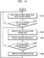
- FIG. 11 is a flowchart illustrating a signal reception process in the wireless communication method of the wireless wearable communication device according to one embodiment of the present invention.
- the antenna 220 stands by the input of a digital voice signal.
- the controller 140 determines whether an ID and a paring code of another wearable wireless communication device are included in a signal input through the antenna 220.
- the controller 140 displays the ID and the pairing code of the other wearable wireless communication device that are input, on the display portion 210.
- the controller 140 outputs the digital voice signal of the other wearable wireless communication that is input, to the D/A converter 160 and an analog voice signal obtained through conversion at the D/A converter 160 is input through the voice output portion 180.
- the controller 140 determines whether a transmission completion code is included in a transmission signal of the other wearable wireless communication device.
- FIG. 12 is a flowchart illustrating a process of performing full duplex communication in the wireless communication method of the wireless wearable communication device according to one embodiment of the present invention.
- the receiver 110 stands by the input of an analog voice signal.
- the controller 140 determines whether a PTT signal is input through the input portion 200 or whether a voice data existence signal is input through the comparator 190.
- the controller 140 In operation S330, when the PTT signal is input or the voice data existence signal is input, the controller 140 outputs a basic packet to the RF transceiver 150.
- the controller 140 determines whether to generate a control INST.
- operation S350 when it is determined to generate the control INST, the controller 140 outputs the basic packet including a control INST packet to the RF transceiver 150. Otherwise, in operation S355, when it is determined not to generate the control INST, the controller 140 continuously outputs the basic packet to the RF transceiver 150.
- the controller 140 determines whether transmission is completed, that is, whether the other wearable wireless communication device remains in a condition of completing reception.
- the controller 140 determines that transmission is completed, the receiver 110 returns to operation before the operation of standing by the input of the analog voice signal.
- the controller 140 determines that transmission is not completed as well as the PTT signal is input or the voice data existence signal is input, the controller 140 returns to operation before the operation of outputting the basic packet to the RF transceiver 150.
- the antenna 220 stands by the input of a digital voice signal.
- the controller 140 determines whether an ID and a paring code of another wearable wireless communication device are included in a signal input through the antenna 220.
- the controller 140 determines whether a control INST and the corresponding signal are received together.
- reception packet information is output through the display portion 210 and voice data is output through the voice output portion 180 according to the executing of the control INST by the controller 140.
- the controller 140 determines whether reception is completed, that is, whether the other wearable wireless communication device remains in a condition of completing transmission.
- the controller 140 returns to operation before the operation of standing by the input of the digital voice signal at the antenna 220.
- the controller 140 as well as it is determined that the ID and the pairing code of the other wearable wireless communication device are included in the signal received at the antenna 220, the controller 140 returns to operation before the operation of determining whether the control INST and the corresponding signal are received together.
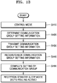
- FIG. 13 is a flowchart illustrating a communication group setting method according to one embodiment of the present invention.
- the wearable wireless communication device 100 intended to set a communication group is set as a control mode.
- the controller 140 of the wearable wireless communication device 100 determines communication group setting information of the communication group to be set.
- the communication group setting information may include, for example, an ID, a paring code, a master, a slave, a control INST and the like of a wireless communication device to be included in the communication group.
- the controller 140 of the wearable wireless communication device 100 transmits the communication group setting information through the RF transceiver 150 and the antenna 220.
- other wireless communication devices receive the communication group setting information and check the received communication group setting information when there is a group participation permission (or an implied permission).
- the other wireless communication devices store and set the received communication group setting information in such a way that a communication group including the wearable wireless communication device 100 and the other wireless communication devices is set.
- the wearable wireless communication device 100 and the other wireless communication devices convert into a reception-standby mode. Then, it comes to a state in which communication is available among the wireless communication devices included in the communication group.
- the communication group setting method it is possible to set a communication group among wireless communication devices within a range of transmitting communication group setting information, that is, within a communication range of the wearable wireless communication device 100 intended to set the communication group.
- a communication group among wireless communication devices within a limited range smaller than a so-called private communication group, that is, a wireless communication range. For example, a communication group of people gather within several meters or several ten meters is set.
- FIG. 14 is a flowchart illustrating a communication group setting method according to another embodiment of the present invention.
- the wearable wireless communication device 100 intended to set a communication group is set as a control mode.
- the controller 140 of the wearable wireless communication device 100 determines communication group setting information of the communication group to be set.
- the communication group setting information may include, for example, an ID, a paring code, a master, a slave, a control INST and the like of a wireless communication device to be included in the communication group.
- the controller 140 of the wearable wireless communication device 100 determines whether setting of the communication group is a first group setting.
- the setting may not be determined as the first group setting.
- the setting may be determined as the first group setting.
- the controller 140 of the wearable wireless communication device 100 transmits the communication group setting information through the RF transceiver 150 and the antenna 220 (operation S430).
- new communication group setting information may be transmitted to the wireless communication devices in the communication group that is already set.
- the controller 140 of the wearable wireless communication device 100 transmits communication group setting information to wireless communication devices within a limited range using a DTMF signal.
- the DTMF signal is sent out as a voice through the voice output portion 180, for example, a speaker.
- the voice since the voice reaches only a limited distance, it is possible to set a communication group among the wireless communication devices within the limited range.
- the controller 140 of the wearable wireless communication device 100 checks whether an external speaker and a microphone of the wearable wireless communication device 100 are in an ON state. Since it is impossible to send out the voice when the external speaker and the microphone are not in the ON state, the controller 140 of the wearable wireless communication device 100 transmits the communication group setting information through the RF transceiver 150 and the antenna 220 (operation S430).
- the controller 140 of the wearable wireless communication device 100 converts the communication group setting information into a DTMF signal.
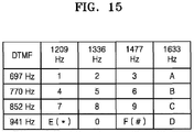
- a hexadecimal number value may be shown using an overlapped tone (a combination of two frequencies).
- FIG. 15 is a view illustrating an example of a DTMF signal. Each line indicates a low frequency component, and each column indicates a radio frequency component. As shown in the drawing, hexadecimal numbers from 0 to F may be shown with the frequency component of the 4 ⁇ 4 matrix.
- the controller of the wearable wireless communication device 100 sends out the DTMF signal through the voice output portion 180.
- eight overlapped tones are sequentially sent out through the voice output portion 180.
- the DTMF signal may be transferred within several meters to a dozen or more meters. Accordingly, it is possible to set a communication group among wireless communication devices within a range of several meters to a dozen or more meters.
- a frequency of the DTMF signal is in an ultrasonic band, it is possible transmit and receive the DTMF signal even at a place where there is a lot of ambient noise.
- the controller 140 of the other wireless communication devices that receive the DTMF signal the communication group setting information is obtained by decoding the received DTMF signal when there is a group participation permission (or an implied permission) from the user.
- the controllers of the other wireless communication devices may obtain the communication group setting information by restoring corresponding hexadecimal data from the received DTMF signal.
- the other wireless communication devices store and set the obtained communication group setting information in such a way that a communication group including the wearable wireless communication device 100 and the other wireless communication devices is set.
- the wearable wireless communication device 100 and the other wireless communication devices convert into a reception-standby mode. Then, it comes to a state in which communication is available among the wireless communication devices included in the communication group.
- FIG. 16 is a flowchart illustrating a communication group setting method according to still another embodiment of the present invention.
- the wearable wireless communication device 100 intended to set a communication group is set as a control mode.
- the controller 140 of the wearable wireless communication device 100 determines communication group setting information of the communication group to be set.
- the communication group setting information may include, for example, an ID, a paring code, a master, a slave, a control INST and the like of a wireless communication device to be included in the communication group.
- the controller 140 of the wearable wireless communication device 100 determines whether setting of the communication group is a first group setting.
- the setting may not be determined as the first group setting.
- the setting may be determined as the first group setting.
- the controller 140 of the wearable wireless communication device 100 transmits the communication group setting information through the RF transceiver 150 and the antenna 220 (operation S430).
- new communication group setting information may be transmitted to the wireless communication devices in the communication group that is already set.
- the controller 140 of the wearable wireless communication device 100 checks whether an external speaker and a microphone of the wearable wireless communication device 100 are in an ON state. When the external speaker and the microphone are in the ON state, like the embodiment of FIG. 14 , the controller 140 of the wearable wireless communication device 100 converts the communication group setting information into a DTMF signal (operation S530) and sends out the DTMF signal through the voice output portion 180 (operation S540).
- the controller 140 of the wearable wireless communication device 100 performs operation S610 and transmits the communication group setting information including a certain RSSI reference value operation S610 as described below. Then, another wireless communication device that receives the RSSI reference value may compare the RSSI reference value with a measured RSSI value and may determine whether to participate in the communication group according to a result thereof. Since the measured RSSI value depends on a distance, performing like this, it is possible to set a communication group among wireless communication devices within a limited range.
- the DTMF signal may not be used and an RSSI value may be used.
- the operations S520 to S560 are omitted from the flowchart of FIG. 16 and operation S610 may be performed directly when the setting is the first group setting in operation S510.
- the controller 140 of the wearable wireless communication device 100 determines whether to use the RSSI value in the setting of the communication group. Here, depending on a user command or a preset setting, it may be determined whether to use the RSSI value. When it is determined not to use the RSSI value, the controller 140 of the wearable wireless communication device 100 transmits the communication group setting information through the RF transceiver 150 and the antenna 220 (operation S430).
- the controller 140 of the wearable wireless communication device 100 inputs a certain RSSI reference value into the communication group setting information.
- the communication group setting information may include a control INST, for example, it is possible to input the RSSI reference value into the Reserve1 or Reserve2 area of the control INST packet shown in FIG. 3 .
- the controller 140 of the wearable wireless communication device 100 transmits the communication group setting information including the RSSI reference value through the RF transceiver 150 and the antenna 220.
- operation S640 other wireless communication devices receive the communication group setting information including the RSSI reference value through antennas and controllers of the other wireless communication devices extract the RSSI reference value from the received communication group setting information and, on the other hand, measure RSSI values of received signals.
- the controllers of the other wireless communication devices compare the measured RSSI values with the RSSI reference value extracted from the communication group setting information and determine whether the measured RSSI values are the RSSI reference value or more.
- the RSSI reference value may be determined as a value adequate according to a range for setting the communication group and may be changed according to user settings. For example, when the range for setting the communication group is several meters, the RSSI reference value may be determined as 90% of the maximum RSSI value.
- the controllers of the other wireless communication devices check the received communication group setting information and obtain the communication group setting information such as an ID, a paring code, a master, a slave, a control INST and the like of a wireless communication device to be included in the communication group.
- the other wireless communication devices store and set the communication group setting information in such a way that a communication group including the wearable wireless communication device 100 and the other wireless communication devices is set.
- the wearable wireless communication device 100 and the other wireless communication devices convert into a reception-standby mode. Then, it comes to a state in which communication is available among the wireless communication devices included in the communication group.
- FIG. 17 is a view illustrating an example in which the wireless wearable communication device according to one embodiment of the present invention operates as a repeater or a relay.
- the repeater means a relay function of shaping a waveform or amplifying such as regenerating a decreased signal or increasing output for long-distance transmission of a wireless signal to be transmitted.
- the relay means a function of extending a communication distance or the number of communication terminals by providing one or more repeaters between a transmitting end and a receiving end in a wireless communication network.
- the wearable wireless communication device 100 may be set to be a repeater mode.
- the controller 140 may change a transmission/reception ID and may amplify a wireless signal received through the antenna 220 with certain power and transmit the amplified wireless signal through the antenna 220 again.
- two or more wireless communication devices in the repeater mode that receive the wireless signal may compare strengths of receiving power through communication to allow a wireless communication device having the greatest receiving power may perform the repeater function.
- a wireless communication device A 710 transmits a wireless signal.
- a wireless communication device B 750 is at a long distance from the wireless communication device A 710 and may not directly receive the wireless signal.
- Each of the wireless communication devices ID1, ID2, and ID3 720, 730, and 740 receives a signal from the wireless communication device A 710 and compares strength of receiving power through communication. Then, the wireless communication device ID1 720 having the greatest receiving power amplifies and transmits the signal from the wireless communication device A 710 again.
- Each of the wireless communication devices ID2 and ID3 730 and 740 receives a signal from the wireless communication device ID1 720 and compares strength of receiving power through communication. Then, the wireless communication device ID3 740 having the greatest receiving power amplifies and transmits the signal from the wireless communication device ID1 720 again. Then, the wireless communication device B 750 receives a wireless signal from the wireless communication device ID3 740. Occasionally, the wireless communication device B 750 may receive the signal transmitted from the wireless communication device ID1 720. However, since strength of the signal received from the wireless communication device ID3 740 is stronger, the signal received from the wireless communication device ID3 740 is selected.
- the signal transmitted by the wireless communication device A 710 is transmitted to the wireless communication device B 750 via the wireless communication device ID3 740.
- the signal transmitted by the wireless communication device B 720 is transmitted to the wireless communication device A 710 via the wireless communication device ID1 720.
- FIG. 18 is a view illustrating an example in which the wireless wearable communication device according to one embodiment of the present invention operates as a donor radio.
- the donor radio means a function of transmitting a signal outside a VoIP network through a VoIP apparatus such as a gateway, a switch, a router and the like or receives a signal from the VoIP network through a VoIP apparatus and transmits the signal to the outside of the VoIP network.
- a VoIP apparatus such as a gateway, a switch, a router and the like
- the wearable wireless communication device may communicate with wireless communication devices in any areas in the world connected to the VoIP network.
- the controller 140 may transmit a signal from a VoIP apparatus such as a gateway, a switch, a router and the like through the antenna 220 or may transmit a signal received from another wireless communication device through the antenna 220 to a VoIP apparatus such as a gateway, a switch, a router and the like to transmit the signal inside the VoIP network.
- a VoIP apparatus such as a gateway, a switch, a router and the like
- a VoIP apparatus such as a gateway, a switch, a router and the like to transmit the signal inside the VoIP network.
- a first VoIP apparatus 910 and a second VoIP apparatus 920 are connected to a VoIP network or a VoIP server and a first wireless communication device 811 of a first communication group 810 is connected to the first VoIP apparatus 910 and a second wireless communication device 821 of a second communication group 820 is connected to the second VoIP apparatus 920. That is, the first wireless communication device 811 and the second wireless communication device 821 operate as donor radios.
- the first and second wireless communication devices 811 and 821 may be connected to the first and second VoIP apparatuses 910 and 920 respectively and may transmit and receive signals through audio input/output ports (corresponding to the receiver 110 and the voice output portion 180 of FIG. 1 ).
- the first and second wireless communication devices 811 and 821 and the first and second VoIP apparatuses 910 and 920 may transmit and receive signals through wireless communication.
- the first wireless communication device 811 When a signal is received from the first VoIP apparatus 910, the first wireless communication device 811 transmits the corresponding signal to other wireless communication devices in the first communication group 810. When signals are received from the other wireless communication devices in the first communication group 810, the first wireless communication device 811 transmits the corresponding signals to the first VoIP apparatus 910.
- the second wireless communication device 821 transmits the corresponding signal to other wireless communication devices in the second communication group 820.
- the second wireless communication device 821 transmits the corresponding signals to the second VoIP apparatus 920.
- a signal transmitted by the wireless communication device in the first communication group 810 is transmitted to the wireless communication devices in the second communication group 820 via the first wireless communication device 811, the first VoIP apparatus 910, the VoIP network, the second VoIP apparatus 920, and the second wireless communication device 821.
- a signal transmitted by the wireless communication device in the second communication group 820 is transmitted to the wireless communication devices in the first communication group 810 via the second wireless communication device 821, the second VoIP apparatus 920, the VoIP network, the first VoIP apparatus 910, and the first wireless communication device 811.
- the wireless communication devices of the first communication group 810 and the wireless communication devices of the second communication group 820 may communicate with one another as belonging to one communication group.
- FIGS. 19 and 20 illustrate structures for attaching the wearable wireless communication device according to one embodiment of the present invention to a body or user's clothing.
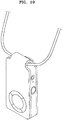
- FIG. 19 is a view illustrating a state in which a strap is connected to a case of the speaker type wireless wearable communication device of FIG. 8 .
- a strap As shown in the drawing, it is possible to wear the speaker type wireless communication device around a neck by connecting a strap thereto. Also, as shown in FIG. 8 , it is possible to attach the wearable wireless communication device to user's clothing and the like using a clothespin type clip.
- FIG. 20 is a view illustrating a structure in which the earphone type wireless wearable communication device of FIG. 9 is attached to user's clothing.
- the case of the earphone type wearable wireless communication device includes a magnet to be attached to a magnet (or a metal piece) provided at the user's clothing to be attached to the user's clothing.
- a magnet to be attached to a magnet (or a metal piece) provided at the user's clothing to be attached to the user's clothing.
- a wearable wireless communication device may perform transmission and reception at the same time using a time sharing method through a full duplex function.
- a wearable wireless communication device may clearly perform communication among the wearable wireless communication devices in the corresponding communication group without noise and miscommunication as less as possible because it is possible to allow communication to be performed only among wearable wireless communication devices in a communication group set by a division function using a code combination.
- a wearable wireless communication device may greatly reduce power consumption in a reception-standby state by repeating one period including a sleep mode and an auto polling mode in the reception-standby state.
- a user may automatically send out a voice signal input to a receiver through an RF transceiver and an antenna of a wearable wireless communication device even without additional operation for inputting a voice through a PTT button and the like.
- a wearable wireless communication device that is easily worn due to an ergonomically designed case applied thereto and allows a user to feel comfortable without inconvenience even for a long time use.
- a wearable wireless communication device that may remotely control transmission of another wearable wireless communication device and may form a master-slave relationship between a plurality of wearable wireless communication devices to more efficiently perform voice communication between the wearable wireless communication devices between which the master-slave relationship is formed as described above.
- a wearable wireless communication device that may set a communication group with other wireless communication devices within a limited range by converting and sending out communication group setting information into a DTMF signal or by transmitting communication group setting information including a certain RSSI reference value and a wireless communication setting method using the method.
Landscapes
- Engineering & Computer Science (AREA)
- Multimedia (AREA)
- Computer Networks & Wireless Communication (AREA)
- Signal Processing (AREA)
- Mobile Radio Communication Systems (AREA)
Priority Applications (1)
| Application Number | Priority Date | Filing Date | Title |
|---|---|---|---|
| EP17150903.7A EP3346737B1 (fr) | 2017-01-10 | 2017-01-10 | Dispositif de communication sans fil vestimentaire et procédé de réglage de groupe de communication l'utilisant |
Applications Claiming Priority (1)
| Application Number | Priority Date | Filing Date | Title |
|---|---|---|---|
| EP17150903.7A EP3346737B1 (fr) | 2017-01-10 | 2017-01-10 | Dispositif de communication sans fil vestimentaire et procédé de réglage de groupe de communication l'utilisant |
Publications (2)
| Publication Number | Publication Date |
|---|---|
| EP3346737A1 true EP3346737A1 (fr) | 2018-07-11 |
| EP3346737B1 EP3346737B1 (fr) | 2020-11-18 |
Family
ID=57909441
Family Applications (1)
| Application Number | Title | Priority Date | Filing Date |
|---|---|---|---|
| EP17150903.7A Active EP3346737B1 (fr) | 2017-01-10 | 2017-01-10 | Dispositif de communication sans fil vestimentaire et procédé de réglage de groupe de communication l'utilisant |
Country Status (1)
| Country | Link |
|---|---|
| EP (1) | EP3346737B1 (fr) |
Cited By (1)
| Publication number | Priority date | Publication date | Assignee | Title |
|---|---|---|---|---|
| CN111683358A (zh) * | 2020-07-06 | 2020-09-18 | Oppo(重庆)智能科技有限公司 | 控制方法、装置、移动终端、存储介质和无线耳机 |
Families Citing this family (1)
| Publication number | Priority date | Publication date | Assignee | Title |
|---|---|---|---|---|
| WO2024072484A1 (fr) * | 2022-09-28 | 2024-04-04 | Skyworks Solutions, Inc. | Systèmes, dispositifs et procédés d'amplification audio |
Citations (3)
| Publication number | Priority date | Publication date | Assignee | Title |
|---|---|---|---|---|
| US7756255B1 (en) * | 2004-05-25 | 2010-07-13 | Sprint Spectrum L.P. | Method and system for delivering a voice message from a telephone to a group of recipients |
| KR101550648B1 (ko) * | 2015-03-24 | 2015-09-08 | (주)스타넥스 | 웨어러블 무선 통신 장치 및 이를 이용한 무선 통신 방법 |
| US20160164726A1 (en) * | 2014-12-05 | 2016-06-09 | Dominant Technologies, LLC | Communication and data handling in a mesh network using duplex radios |
-
2017
- 2017-01-10 EP EP17150903.7A patent/EP3346737B1/fr active Active
Patent Citations (3)
| Publication number | Priority date | Publication date | Assignee | Title |
|---|---|---|---|---|
| US7756255B1 (en) * | 2004-05-25 | 2010-07-13 | Sprint Spectrum L.P. | Method and system for delivering a voice message from a telephone to a group of recipients |
| US20160164726A1 (en) * | 2014-12-05 | 2016-06-09 | Dominant Technologies, LLC | Communication and data handling in a mesh network using duplex radios |
| KR101550648B1 (ko) * | 2015-03-24 | 2015-09-08 | (주)스타넥스 | 웨어러블 무선 통신 장치 및 이를 이용한 무선 통신 방법 |
Cited By (1)
| Publication number | Priority date | Publication date | Assignee | Title |
|---|---|---|---|---|
| CN111683358A (zh) * | 2020-07-06 | 2020-09-18 | Oppo(重庆)智能科技有限公司 | 控制方法、装置、移动终端、存储介质和无线耳机 |
Also Published As
| Publication number | Publication date |
|---|---|
| EP3346737B1 (fr) | 2020-11-18 |
Similar Documents
| Publication | Publication Date | Title |
|---|---|---|
| EP2400776B1 (fr) | Téléphone cellulaire avec une communication radio et cellulaire simultanée | |
| AU2017392020B2 (en) | Wearable wireless communication device and communication group setting method using the same | |
| AU2018323559B2 (en) | Smart phone and bluetooth earset having digital two-way radio function | |
| AU2018355864B2 (en) | Smart watch having digital radio function | |
| EP3346737B1 (fr) | Dispositif de communication sans fil vestimentaire et procédé de réglage de groupe de communication l'utilisant | |
| KR101550648B1 (ko) | 웨어러블 무선 통신 장치 및 이를 이용한 무선 통신 방법 | |
| CN105338194A (zh) | 一种手机对讲伴侣 | |
| KR20140067447A (ko) | 스마트 디지털 무전기 시스템 | |
| CN111770408A (zh) | 控制方法、装置、无线耳机和存储介质 | |
| KR20040106786A (ko) | 블루투스를 이용한 무선 송수신 시스템 및 그 방법 | |
| KR100504952B1 (ko) | 휴대전화 안전 통화 장치 | |
| KR20040110714A (ko) | 블루투스를 이용한 무선 송수신 시스템 | |
| PT1558013E (pt) | Processo e terminais comunicantes para a emissão e recepção à distância de sinais de telefonia audio e/ou video | |
| KR20110013557A (ko) | 스마트폰을 무전기로 사용할 수 있게 해주는 외부 부착형 에프알에스 통신 모듈 | |
| JP2008236701A (ja) | 通信装置 | |
| KR20040110717A (ko) | 블루투스를 이용한 무선 송수신 시스템 및 그 방법 | |
| KR20000031183A (ko) | 휴대장치를 가지는 무선가입자장치 및 그 제어방법 | |
| KR20040110716A (ko) | 블루투스를 이용한 무선 송수신 시스템 |
Legal Events
| Date | Code | Title | Description |
|---|---|---|---|
| PUAI | Public reference made under article 153(3) epc to a published international application that has entered the european phase |
Free format text: ORIGINAL CODE: 0009012 |
|
| STAA | Information on the status of an ep patent application or granted ep patent |
Free format text: STATUS: THE APPLICATION HAS BEEN PUBLISHED |
|
| AK | Designated contracting states |
Kind code of ref document: A1 Designated state(s): AL AT BE BG CH CY CZ DE DK EE ES FI FR GB GR HR HU IE IS IT LI LT LU LV MC MK MT NL NO PL PT RO RS SE SI SK SM TR |
|
| AX | Request for extension of the european patent |
Extension state: BA ME |
|
| STAA | Information on the status of an ep patent application or granted ep patent |
Free format text: STATUS: REQUEST FOR EXAMINATION WAS MADE |
|
| 17P | Request for examination filed |
Effective date: 20190107 |
|
| RBV | Designated contracting states (corrected) |
Designated state(s): AL AT BE BG CH CY CZ DE DK EE ES FI FR GB GR HR HU IE IS IT LI LT LU LV MC MK MT NL NO PL PT RO RS SE SI SK SM TR |
|
| GRAP | Despatch of communication of intention to grant a patent |
Free format text: ORIGINAL CODE: EPIDOSNIGR1 |
|
| STAA | Information on the status of an ep patent application or granted ep patent |
Free format text: STATUS: GRANT OF PATENT IS INTENDED |
|
| INTG | Intention to grant announced |
Effective date: 20200528 |
|
| GRAS | Grant fee paid |
Free format text: ORIGINAL CODE: EPIDOSNIGR3 |
|
| GRAA | (expected) grant |
Free format text: ORIGINAL CODE: 0009210 |
|
| STAA | Information on the status of an ep patent application or granted ep patent |
Free format text: STATUS: THE PATENT HAS BEEN GRANTED |
|
| AK | Designated contracting states |
Kind code of ref document: B1 Designated state(s): AL AT BE BG CH CY CZ DE DK EE ES FI FR GB GR HR HU IE IS IT LI LT LU LV MC MK MT NL NO PL PT RO RS SE SI SK SM TR |
|
| REG | Reference to a national code |
Ref country code: GB Ref legal event code: FG4D |
|
| REG | Reference to a national code |
Ref country code: CH Ref legal event code: EP |
|
| REG | Reference to a national code |
Ref country code: DE Ref legal event code: R096 Ref document number: 602017027592 Country of ref document: DE |
|
| REG | Reference to a national code |
Ref country code: IE Ref legal event code: FG4D |
|
| REG | Reference to a national code |
Ref country code: AT Ref legal event code: REF Ref document number: 1337065 Country of ref document: AT Kind code of ref document: T Effective date: 20201215 |
|
| REG | Reference to a national code |
Ref country code: NO Ref legal event code: T2 Effective date: 20201118 |
|
| REG | Reference to a national code |
Ref country code: CH Ref legal event code: NV Representative=s name: OFFICE ERNEST T. FREYLINGER S.A., CH |
|
| REG | Reference to a national code |
Ref country code: SE Ref legal event code: TRGR |
|
| REG | Reference to a national code |
Ref country code: NL Ref legal event code: FP |
|
| REG | Reference to a national code |
Ref country code: AT Ref legal event code: MK05 Ref document number: 1337065 Country of ref document: AT Kind code of ref document: T Effective date: 20201118 |
|
| PG25 | Lapsed in a contracting state [announced via postgrant information from national office to epo] |
Ref country code: PT Free format text: LAPSE BECAUSE OF FAILURE TO SUBMIT A TRANSLATION OF THE DESCRIPTION OR TO PAY THE FEE WITHIN THE PRESCRIBED TIME-LIMIT Effective date: 20210318 Ref country code: RS Free format text: LAPSE BECAUSE OF FAILURE TO SUBMIT A TRANSLATION OF THE DESCRIPTION OR TO PAY THE FEE WITHIN THE PRESCRIBED TIME-LIMIT Effective date: 20201118 Ref country code: GR Free format text: LAPSE BECAUSE OF FAILURE TO SUBMIT A TRANSLATION OF THE DESCRIPTION OR TO PAY THE FEE WITHIN THE PRESCRIBED TIME-LIMIT Effective date: 20210219 Ref country code: FI Free format text: LAPSE BECAUSE OF FAILURE TO SUBMIT A TRANSLATION OF THE DESCRIPTION OR TO PAY THE FEE WITHIN THE PRESCRIBED TIME-LIMIT Effective date: 20201118 |
|
| PG25 | Lapsed in a contracting state [announced via postgrant information from national office to epo] |
Ref country code: AT Free format text: LAPSE BECAUSE OF FAILURE TO SUBMIT A TRANSLATION OF THE DESCRIPTION OR TO PAY THE FEE WITHIN THE PRESCRIBED TIME-LIMIT Effective date: 20201118 Ref country code: BG Free format text: LAPSE BECAUSE OF FAILURE TO SUBMIT A TRANSLATION OF THE DESCRIPTION OR TO PAY THE FEE WITHIN THE PRESCRIBED TIME-LIMIT Effective date: 20210218 Ref country code: IS Free format text: LAPSE BECAUSE OF FAILURE TO SUBMIT A TRANSLATION OF THE DESCRIPTION OR TO PAY THE FEE WITHIN THE PRESCRIBED TIME-LIMIT Effective date: 20210318 Ref country code: LV Free format text: LAPSE BECAUSE OF FAILURE TO SUBMIT A TRANSLATION OF THE DESCRIPTION OR TO PAY THE FEE WITHIN THE PRESCRIBED TIME-LIMIT Effective date: 20201118 Ref country code: PL Free format text: LAPSE BECAUSE OF FAILURE TO SUBMIT A TRANSLATION OF THE DESCRIPTION OR TO PAY THE FEE WITHIN THE PRESCRIBED TIME-LIMIT Effective date: 20201118 |
|
| REG | Reference to a national code |
Ref country code: LT Ref legal event code: MG9D |
|
| PG25 | Lapsed in a contracting state [announced via postgrant information from national office to epo] |
Ref country code: HR Free format text: LAPSE BECAUSE OF FAILURE TO SUBMIT A TRANSLATION OF THE DESCRIPTION OR TO PAY THE FEE WITHIN THE PRESCRIBED TIME-LIMIT Effective date: 20201118 |
|
| PG25 | Lapsed in a contracting state [announced via postgrant information from national office to epo] |
Ref country code: RO Free format text: LAPSE BECAUSE OF FAILURE TO SUBMIT A TRANSLATION OF THE DESCRIPTION OR TO PAY THE FEE WITHIN THE PRESCRIBED TIME-LIMIT Effective date: 20201118 Ref country code: SK Free format text: LAPSE BECAUSE OF FAILURE TO SUBMIT A TRANSLATION OF THE DESCRIPTION OR TO PAY THE FEE WITHIN THE PRESCRIBED TIME-LIMIT Effective date: 20201118 Ref country code: EE Free format text: LAPSE BECAUSE OF FAILURE TO SUBMIT A TRANSLATION OF THE DESCRIPTION OR TO PAY THE FEE WITHIN THE PRESCRIBED TIME-LIMIT Effective date: 20201118 Ref country code: CZ Free format text: LAPSE BECAUSE OF FAILURE TO SUBMIT A TRANSLATION OF THE DESCRIPTION OR TO PAY THE FEE WITHIN THE PRESCRIBED TIME-LIMIT Effective date: 20201118 Ref country code: SM Free format text: LAPSE BECAUSE OF FAILURE TO SUBMIT A TRANSLATION OF THE DESCRIPTION OR TO PAY THE FEE WITHIN THE PRESCRIBED TIME-LIMIT Effective date: 20201118 Ref country code: LT Free format text: LAPSE BECAUSE OF FAILURE TO SUBMIT A TRANSLATION OF THE DESCRIPTION OR TO PAY THE FEE WITHIN THE PRESCRIBED TIME-LIMIT Effective date: 20201118 |
|
| REG | Reference to a national code |
Ref country code: DE Ref legal event code: R097 Ref document number: 602017027592 Country of ref document: DE |
|
| PG25 | Lapsed in a contracting state [announced via postgrant information from national office to epo] |
Ref country code: DK Free format text: LAPSE BECAUSE OF FAILURE TO SUBMIT A TRANSLATION OF THE DESCRIPTION OR TO PAY THE FEE WITHIN THE PRESCRIBED TIME-LIMIT Effective date: 20201118 Ref country code: MC Free format text: LAPSE BECAUSE OF FAILURE TO SUBMIT A TRANSLATION OF THE DESCRIPTION OR TO PAY THE FEE WITHIN THE PRESCRIBED TIME-LIMIT Effective date: 20201118 |
|
| PLBE | No opposition filed within time limit |
Free format text: ORIGINAL CODE: 0009261 |
|
| STAA | Information on the status of an ep patent application or granted ep patent |
Free format text: STATUS: NO OPPOSITION FILED WITHIN TIME LIMIT |
|
| PG25 | Lapsed in a contracting state [announced via postgrant information from national office to epo] |
Ref country code: LU Free format text: LAPSE BECAUSE OF NON-PAYMENT OF DUE FEES Effective date: 20210110 |
|
| REG | Reference to a national code |
Ref country code: BE Ref legal event code: MM Effective date: 20210131 |
|
| 26N | No opposition filed |
Effective date: 20210819 |
|
| PG25 | Lapsed in a contracting state [announced via postgrant information from national office to epo] |
Ref country code: IT Free format text: LAPSE BECAUSE OF FAILURE TO SUBMIT A TRANSLATION OF THE DESCRIPTION OR TO PAY THE FEE WITHIN THE PRESCRIBED TIME-LIMIT Effective date: 20201118 Ref country code: AL Free format text: LAPSE BECAUSE OF FAILURE TO SUBMIT A TRANSLATION OF THE DESCRIPTION OR TO PAY THE FEE WITHIN THE PRESCRIBED TIME-LIMIT Effective date: 20201118 |
|
| PG25 | Lapsed in a contracting state [announced via postgrant information from national office to epo] |
Ref country code: SI Free format text: LAPSE BECAUSE OF FAILURE TO SUBMIT A TRANSLATION OF THE DESCRIPTION OR TO PAY THE FEE WITHIN THE PRESCRIBED TIME-LIMIT Effective date: 20201118 |
|
| PG25 | Lapsed in a contracting state [announced via postgrant information from national office to epo] |
Ref country code: IE Free format text: LAPSE BECAUSE OF NON-PAYMENT OF DUE FEES Effective date: 20210110 Ref country code: ES Free format text: LAPSE BECAUSE OF FAILURE TO SUBMIT A TRANSLATION OF THE DESCRIPTION OR TO PAY THE FEE WITHIN THE PRESCRIBED TIME-LIMIT Effective date: 20201118 |
|
| PG25 | Lapsed in a contracting state [announced via postgrant information from national office to epo] |
Ref country code: IS Free format text: LAPSE BECAUSE OF FAILURE TO SUBMIT A TRANSLATION OF THE DESCRIPTION OR TO PAY THE FEE WITHIN THE PRESCRIBED TIME-LIMIT Effective date: 20210318 |
|
| PG25 | Lapsed in a contracting state [announced via postgrant information from national office to epo] |
Ref country code: BE Free format text: LAPSE BECAUSE OF NON-PAYMENT OF DUE FEES Effective date: 20210131 |
|
| PGFP | Annual fee paid to national office [announced via postgrant information from national office to epo] |
Ref country code: NO Payment date: 20230119 Year of fee payment: 7 Ref country code: CH Payment date: 20230119 Year of fee payment: 7 |
|
| PGFP | Annual fee paid to national office [announced via postgrant information from national office to epo] |
Ref country code: SE Payment date: 20230119 Year of fee payment: 7 |
|
| PG25 | Lapsed in a contracting state [announced via postgrant information from national office to epo] |
Ref country code: CY Free format text: LAPSE BECAUSE OF FAILURE TO SUBMIT A TRANSLATION OF THE DESCRIPTION OR TO PAY THE FEE WITHIN THE PRESCRIBED TIME-LIMIT Effective date: 20201118 |
|
| PGFP | Annual fee paid to national office [announced via postgrant information from national office to epo] |
Ref country code: NL Payment date: 20230120 Year of fee payment: 7 |
|
| PG25 | Lapsed in a contracting state [announced via postgrant information from national office to epo] |
Ref country code: HU Free format text: LAPSE BECAUSE OF FAILURE TO SUBMIT A TRANSLATION OF THE DESCRIPTION OR TO PAY THE FEE WITHIN THE PRESCRIBED TIME-LIMIT; INVALID AB INITIO Effective date: 20170110 |
|
| PG25 | Lapsed in a contracting state [announced via postgrant information from national office to epo] |
Ref country code: MK Free format text: LAPSE BECAUSE OF FAILURE TO SUBMIT A TRANSLATION OF THE DESCRIPTION OR TO PAY THE FEE WITHIN THE PRESCRIBED TIME-LIMIT Effective date: 20201118 |
|
| PG25 | Lapsed in a contracting state [announced via postgrant information from national office to epo] |
Ref country code: TR Free format text: LAPSE BECAUSE OF FAILURE TO SUBMIT A TRANSLATION OF THE DESCRIPTION OR TO PAY THE FEE WITHIN THE PRESCRIBED TIME-LIMIT Effective date: 20201118 |
|
| REG | Reference to a national code |
Ref country code: CH Ref legal event code: PL |
|
| REG | Reference to a national code |
Ref country code: SE Ref legal event code: EUG |
|
| REG | Reference to a national code |
Ref country code: NL Ref legal event code: MM Effective date: 20240201 |
|
| PG25 | Lapsed in a contracting state [announced via postgrant information from national office to epo] |
Ref country code: MT Free format text: LAPSE BECAUSE OF FAILURE TO SUBMIT A TRANSLATION OF THE DESCRIPTION OR TO PAY THE FEE WITHIN THE PRESCRIBED TIME-LIMIT Effective date: 20201118 |
|
| PG25 | Lapsed in a contracting state [announced via postgrant information from national office to epo] |
Ref country code: NL Free format text: LAPSE BECAUSE OF NON-PAYMENT OF DUE FEES Effective date: 20240201 |
|
| PG25 | Lapsed in a contracting state [announced via postgrant information from national office to epo] |
Ref country code: CH Free format text: LAPSE BECAUSE OF NON-PAYMENT OF DUE FEES Effective date: 20240131 |
|
| PG25 | Lapsed in a contracting state [announced via postgrant information from national office to epo] |
Ref country code: NO Free format text: LAPSE BECAUSE OF NON-PAYMENT OF DUE FEES Effective date: 20240131 Ref country code: NL Free format text: LAPSE BECAUSE OF NON-PAYMENT OF DUE FEES Effective date: 20240201 Ref country code: CH Free format text: LAPSE BECAUSE OF NON-PAYMENT OF DUE FEES Effective date: 20240131 |
|
| PGFP | Annual fee paid to national office [announced via postgrant information from national office to epo] |
Ref country code: GB Payment date: 20241223 Year of fee payment: 9 |
|
| PGFP | Annual fee paid to national office [announced via postgrant information from national office to epo] |
Ref country code: FR Payment date: 20241224 Year of fee payment: 9 |
|
| PGFP | Annual fee paid to national office [announced via postgrant information from national office to epo] |
Ref country code: DE Payment date: 20241223 Year of fee payment: 9 |
|
| PG25 | Lapsed in a contracting state [announced via postgrant information from national office to epo] |
Ref country code: SE Free format text: LAPSE BECAUSE OF NON-PAYMENT OF DUE FEES Effective date: 20240111 |