EP3346802B1 - Vorrichtung zum betreiben einer oder mehrerer beleuchtungsvorrichtungen - Google Patents
Vorrichtung zum betreiben einer oder mehrerer beleuchtungsvorrichtungen Download PDFInfo
- Publication number
- EP3346802B1 EP3346802B1 EP18150018.2A EP18150018A EP3346802B1 EP 3346802 B1 EP3346802 B1 EP 3346802B1 EP 18150018 A EP18150018 A EP 18150018A EP 3346802 B1 EP3346802 B1 EP 3346802B1
- Authority
- EP
- European Patent Office
- Prior art keywords
- transformer
- operating apparatus
- charger
- lighting devices
- electrical energy
- Prior art date
- Legal status (The legal status is an assumption and is not a legal conclusion. Google has not performed a legal analysis and makes no representation as to the accuracy of the status listed.)
- Active
Links
Images

Classifications
-
- H—ELECTRICITY
- H05—ELECTRIC TECHNIQUES NOT OTHERWISE PROVIDED FOR
- H05B—ELECTRIC HEATING; ELECTRIC LIGHT SOURCES NOT OTHERWISE PROVIDED FOR; CIRCUIT ARRANGEMENTS FOR ELECTRIC LIGHT SOURCES, IN GENERAL
- H05B45/00—Circuit arrangements for operating light-emitting diodes [LED]
- H05B45/30—Driver circuits
- H05B45/37—Converter circuits
-
- H—ELECTRICITY
- H05—ELECTRIC TECHNIQUES NOT OTHERWISE PROVIDED FOR
- H05B—ELECTRIC HEATING; ELECTRIC LIGHT SOURCES NOT OTHERWISE PROVIDED FOR; CIRCUIT ARRANGEMENTS FOR ELECTRIC LIGHT SOURCES, IN GENERAL
- H05B45/00—Circuit arrangements for operating light-emitting diodes [LED]
- H05B45/30—Driver circuits
- H05B45/37—Converter circuits
- H05B45/3725—Switched mode power supply [SMPS]
- H05B45/385—Switched mode power supply [SMPS] using flyback topology
-
- H—ELECTRICITY
- H02—GENERATION; CONVERSION OR DISTRIBUTION OF ELECTRIC POWER
- H02J—ELECTRIC POWER NETWORKS; CIRCUIT ARRANGEMENTS OR SYSTEMS FOR SUPPLYING OR DISTRIBUTING ELECTRIC POWER; SYSTEMS FOR STORING ELECTRIC ENERGY
- H02J9/00—Circuit arrangements for emergency or stand-by power supply, e.g. for emergency lighting
- H02J9/04—Circuit arrangements for emergency or stand-by power supply, e.g. for emergency lighting in which the distribution system is disconnected from the normal source and connected to a standby source
-
- H—ELECTRICITY
- H02—GENERATION; CONVERSION OR DISTRIBUTION OF ELECTRIC POWER
- H02J—ELECTRIC POWER NETWORKS; CIRCUIT ARRANGEMENTS OR SYSTEMS FOR SUPPLYING OR DISTRIBUTING ELECTRIC POWER; SYSTEMS FOR STORING ELECTRIC ENERGY
- H02J9/00—Circuit arrangements for emergency or stand-by power supply, e.g. for emergency lighting
- H02J9/04—Circuit arrangements for emergency or stand-by power supply, e.g. for emergency lighting in which the distribution system is disconnected from the normal source and connected to a standby source
- H02J9/06—Circuit arrangements for emergency or stand-by power supply, e.g. for emergency lighting in which the distribution system is disconnected from the normal source and connected to a standby source with automatic change-over, e.g. UPS systems
- H02J9/062—Circuit arrangements for emergency or stand-by power supply, e.g. for emergency lighting in which the distribution system is disconnected from the normal source and connected to a standby source with automatic change-over, e.g. UPS systems for AC powered loads
- H02J9/065—Circuit arrangements for emergency or stand-by power supply, e.g. for emergency lighting in which the distribution system is disconnected from the normal source and connected to a standby source with automatic change-over, e.g. UPS systems for AC powered loads for lighting purposes
-
- H—ELECTRICITY
- H05—ELECTRIC TECHNIQUES NOT OTHERWISE PROVIDED FOR
- H05B—ELECTRIC HEATING; ELECTRIC LIGHT SOURCES NOT OTHERWISE PROVIDED FOR; CIRCUIT ARRANGEMENTS FOR ELECTRIC LIGHT SOURCES, IN GENERAL
- H05B47/00—Circuit arrangements for operating light sources in general, i.e. where the type of light source is not relevant
- H05B47/10—Controlling the light source
- H05B47/17—Operational modes, e.g. switching from manual to automatic mode or prohibiting specific operations
- H05B47/172—Emergency operational modes
Definitions
- the present invention relates to an apparatus for operating one or more lighting devices.
- Document CN 105 323 923 A discloses a light emitting diode (LED) intelligent control circuit and a LED lighting device.
- Document CN 205 812 467 U discloses a LED string control circuit.
- Document US 2014/092646 A1 discloses a soft switching synchronous quasi resonant converter.
- apparatuses arranged to operate one or more lighting devices such as light emitting diodes (LEDs), operate with an existing lighting device driver to add emergency capability.
- An apparatus, arranged to operate the lighting device(s) monitors the mains voltage/current/power/energy, supplied by an external energy or power source respectively and provided further to the lighting device(s), and operates a relay that switches the lighting device driver off during emergency.
- Such emergency case occurs, for example, when the mains voltage/current/power/energy is no longer available or when the supply of the mains voltage/current/power/energy malfunctions.
- the apparatus, arranged to operate lighting device(s) does not obtain the electrical energy (i.e. current, voltage) from the external energy source but from an energy storage device such as battery and provides the electrical energy, obtained from the energy storage device (e.g., battery), to the one or more lighting devices.
- separate components are utilized for providing to the one or more lighting devices the electrical energy: one component arranged to provide to the one or more lighting devices the electrical energy supplied by an external energy source and a further component arranged to provide to the one or more lighting devices the electrical energy supplied by an energy storage device (e.g., a battery).
- an energy storage device e.g., a battery
- an apparatus for operating one or more lighting devices is required that can be manufactured in a cost-effective way, that has a simple structure, and that is small, i.e. does not require a lot of space when installed and used.
- the object of the present invention is to enable an improved operating apparatus arranged to operate one or more lighting devices.
- a provision of an operating apparatus is desired that can be manufactured in a cost-effective way, that has a simple and effective structure, and/or that is small, i.e. does not require a lot of space when installed and used.
- the present invention is based on the idea to use, in an operating apparatus that operates one or more lighting devices such as LEDs, only one transformer for both a charger, which charges an energy storage device for an emergency case, and a lighting device driver, which provides to one or more lighting devices electrical energy (current, voltage) that is supplied by an external electrical energy source in a normal operation case of the operating apparatus.
- the transformer is a part of a converter, arranged to convert electrical energy from one voltage level to another.
- the transformer is a part of a flyback converter, i.e. the operating apparatus is or comprises a flyback converter.
- an operating apparatus is provided that is arranged to operate one or more lighting devices, wherein the operating apparatus comprises: a transformer comprising a primary side and a secondary side, wherein electrical energy is transferred from the primary side to the secondary side of the transformer for operating the one or more lighting devices; a charger arranged on the secondary side of the transformer and configured to charge an energy storage device with the electrical energy, transferred from the primary side to the secondary side of the transformer; a lighting device driver arranged on the secondary side of the transformer and configured to deliver to the one or more lighting devices the electrical energy, transferred from the primary side to the secondary side of the transformer.
- the charger and the lighting device driver are connected to the secondary side of the transformer.
- the primary side of the transformer comprises a primary winding and the secondary side of the transformer comprises at least one secondary winding; and the charger and the lighting device driver are connected to the at least one secondary winding of the transformer.
- the secondary side of the transformer comprises at least two secondary windings; and the charger and the lighting device driver are connected to different secondary windings of the transformer.
- the secondary winding is a tapped secondary winding; the charger and the lighting device driver are connected to the tapped secondary winding; and the charger and/or the lighting device driver are/is connected to a respective point of the tapped secondary winding.
- the electrical energy, transferred from the primary side to the secondary side of the transformer, is selectively and/or alternately provided to the charger or to the lighting device driver.
- the charger and the lighting device driver are operated selectively and/or alternately.
- the charger comprises a charger switch configured to switch on or off the transfer of the electrical energy to the charger.
- the lighting device driver comprises: a main capacitor, which is configured to transfer electrical energy to the one or more lighting devices when the electrical energy flows through the primary side of the transformer and is stored in the transformer; and a main capacitor isolating switch, which is configured to isolate the main capacitor from the charger when the charger charges the energy storage device with the electrical energy, transferred from the primary side to the secondary side of the transformer.
- the operating apparatus if a lighting device voltage, flowing through the one or more lighting devices, is greater than an energy storage device voltage, the operating apparatus is configured to connect the one or more lighting devices to a negative terminal of the energy storage device; and if the lighting device voltage, flowing through the one or more lighting devices, is smaller than the energy storage device voltage, the operating apparatus is configured to connect the one or more lighting devices to a positive terminal of the energy storage device.
- the operating apparatus comprises an isolation barrier between the one or more lighting devices and the energy storage device.
- the operating apparatus is a flyback converter and the transformer is a transformer of the flyback converter.
- the operating apparatus comprises one or more outputs, to which the one or more lighting devices are directly or indirectly connectable and which are configured to provide the electrical energy to the one or more lighting devices.
- the operating apparatus is operated in a normal operation mode and in an emergency operation mode; wherein, in the normal operation mode, the electrical energy is provided to the one or more lighting devices via the lighting device driver; and wherein, in the emergency operation mode, the electrical energy is provided to the one or more lighting devices via the energy storage device.
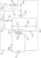
- Fig. 1 shows an operating apparatus 12 according to an embodiment of the present invention.
- the operating apparatus 12 comprises a transformer 121, a charger 127, 128, and a lighting device driver 122, 125, 123, 124. Further, the apparatus 12 comprises outputs 126 that are connectable to one or more lighting devices 13 for providing electrical energy (e.g., current, voltage) to the one or more lighting devices 13.
- the charger switch 127 may be formed by a MOSFET and may comprise an integrated body diode. The charger switch may be formed by a bipolar transistor or an IGBT. There may be an antiparallel diode in parallel to the charger switch 127.
- connection of the operating apparatus 12 to the one or more lighting devices 13 may be a direct connection or an indirect connection. In the case of a direct connection, no further components are present between the operating apparatus 12 and the one or more lighting devices 13. In the case of an indirect connection, further components are present between the operating apparatus 12 and the one or more lighting devices 13.
- the operating apparatus 12 is connected to an external electrical energy source 11, i.e. an external energy source 11. Also here, the connection between the operating apparatus 12 and the external electrical energy source 11 may be a direct or indirect connection.
- the operating apparatus 12 obtains, in a normal operation mode of the operating apparatus 12, the electrical energy (e.g., current, voltage) from the external energy source 11 and provides the obtained electrical energy to the one or more lighting devices 13.
- the electrical energy e.g., current, voltage
- the provision of the electrical energy to the one or more lighting devices 13 is done via the output (s) 126 of the operating apparatus.
- the operating apparatus 12 comprises a transformer 121, via which the electrical energy obtained from the external energy source 11 is provided to the one or more lighting devices 13.
- the transformer 121 comprises a primary side 1211 and a secondary side 1212. According to the present embodiment, the primary side 1211 and the secondary side 1212 are galvanically isolated 1213. The electrical energy obtained from the external energy source 11 is transferred from the primary side 1211 to the secondary side 1212 of the transformer 121.
- the primary side 1211 of the transformer 121 comprises at least one primary winding 1211
- the secondary side 1212 of the transformer 121 comprises at least one secondary winding 1212.
- the electrical energy (e.g., voltage, current) is transferred via the primary side 1211 (i.e. via the primary winding 1211) and stored in the transformer 121.
- the storage of the electrical energy is done by the galvanic isolation 1213.
- the electrical energy, stored via the galvanic isolation is supplied to the secondary side 1212 (i.e. to the secondary winding 1212) of the transformer.
- the operating apparatus 12 is a flyback converter
- the transformer 121 is a transformer of the flyback converter 12.
- the operating apparatus or flyback converter 12 respectively is divided into a primary side and a secondary side.
- the primary side of the operating apparatus or flyback converter 12 respectively comprises components of the operating apparatus or flyback converter 12 respectively that are arranged before the transformer 121. Additionally, the primary side of the operating apparatus or flyback converter 12 respectively comprises the primary side 1211 of the transformer 121.
- the secondary side of the operating apparatus or flyback converter 12 respectively comprises components of the operating apparatus or flyback converter 12 respectively that are arranged after the transformer 121. Additionally, the secondary side of the operating apparatus or flyback converter 12 respectively comprises the secondary side 1212 of the transformer 121.
- the operating apparatus or flyback converter 12 respectively comprises on its primary side a switch 120.
- the switch 120 When the switch 120 is closed (i.e. ON and conductive), the transformer 121 and, particularly, the primary side 1211 of the transformer 121 is connected to the external energy source 11.
- the electrical energy is supplied from the external energy source 11 to the transformer 121 and, particularly, the primary side 1211 of the transformer 121.
- the energy (i.e. current, voltage) and magnetic flux in the transformer 121 increases, storing energy in the transformer 121, particularly, in the galvanic isolation 1213 of the transformer 121.
- the energy i.e.
- the switch 120 of the primary side of the operating device or flyback converter 12 When the switch 120 of the primary side of the operating device or flyback converter 12 is opened (i.e. is OFF and non-conductive), the energy transfer from the external energy source 11 is stopped. The energy (current, voltage) on the primary side 1211 of the transformer 121 and the magnetic flux drops. The energy (current, voltage) on the secondary side 1212 becomes positive. Thus, the diode 122 is forward biased (i.e. is not blocked), or, in case that instead the diode a switch 122 is used, the switch 122 is closed (i.e. is ON and non-conductive). In this way, the electrical energy is allowed to flow from the transformer 121 to the one or more lighting devices 13 (e.g., LEDs).
- the one or more lighting devices 13 e.g., LEDs
- the electrical energy flows to the one or more lighting devices 13
- electrical energy is stored in a main capacitor 124 of the secondary side of the operating apparatus or flyback converter 12 respectively.
- the energy, stored in the main capacitor 124 is provided to the one or more lighting devices 13 when the switch 120 is closed (i.e. is ON and conductive) and, thus, when no electrical energy flows from the transformer 121 to the one or more lighting devices 13.
- the above described ON- and OFF-phases of the switch 120 of the primary side of the operating apparatus or flyback converter 12 respectively are repeated alternately.
- the switching of the switch 120 can be controlled by a controlling entity.
- the controlling entity is not shown in Fig. 1 . However, this way of controlling the switch 120 is well known and is, therefore, not described in more detail herein.
- the operating apparatus or flyback converter 12 respectively comprises a lighting device driver arranged on the secondary side of the transformer 121 and, thus, also on the secondary side of the operating apparatus or flyback converter 12 respectively.
- the lighting device driver is configured to deliver to the one or more lighting devices 13 the electrical energy (current, voltage), transferred from the primary side 1211 to the secondary side 1212 of the transformer 121, i.e. from the primary side of the operating apparatus or flyback converter 12 to the secondary side of the operating apparatus or flyback converter 12.
- the lighting device driver provides to the one or more lighting devices electrical energy supplied by the external energy source 11.
- the lighting device driver comprises according to the present embodiment at least the diode or switch 122 and the main capacitor 124. Additionally, the lighting device driver comprises according to the present embodiment at least the capacitor 123 and the switch 125.
- the operating device or flyback converter 12 respectively of the present embodiment comprises on its secondary side, besides the lighting device driver, also a charger.
- the charger comprises, according to the present embodiment, a charger switch 127 and an electrical energy storage device 128 such as a battery.
- the charger is arranged to charge the energy storage device 128 with electrical energy, transferred from the primary side 1211 to the secondary side 1212 of the transformer 121.
- both the charger and the lighting device driver are connected to the secondary side 1212 of the transformer 121.
- both the charger and the lighting device driver are connected to the secondary winding 1212 of the transformer 121.
- the electrical energy (current, voltage), transferred from the primary side 1211 to the secondary side 1212 of the transformer 121 is selectively and/or alternately provided to the charger or to the lighting device driver.
- the charger and the lighting device driver are, thus, operated selectively and/or alternately.
- the charger switch 127 is arranged to switch on or off the transfer of the electrical energy to the charger.
- the charger switch 127 If the charger switch 127 is closed (i.e. is ON and is conductive), the electrical energy supplied via the transformer 121 is supplied to the energy storage device 128 such as battery. Thus, the energy storage device 128 is charged.
- the charger switch 127 If the charger switch 127 is open (i.e. is OFF and is not conductive), no electrical energy is supplied to the energy storage device 128, thus, no charging of the energy storage device 128 is executed.
- the charger switch 127 If the charger switch 127 is open (i.e. is OFF and is not conductive) and if electrical energy, supplied via the transformer 121 from the external energy source 11, flows through the secondary side of the operating apparatus or flyback converter 12 respectively (because switch 120 is open (i.e. is OFF and is not conductive)), the charger is deactivated but the lighting device driver is activated. Thus, the electrical energy, supplied via the transformer 121, is used to operate, i.e. to provide energy (current, voltage) to the one or more lighting devices 13 as described above.
- the switching of the charger switch 127 can also be done by a respective controlling entity, for example.
- the switching of the charger switch 127 can be done, for example, according to demand, e.g., according to the charging level of the energy storage device 128.
- the charger switch 127 when the charger is active, i.e. when the charger switch 127 is closed (i.e. is ON and is conductive) and the energy storage device 128 is charged, a high energy amount (voltage, power) occurs across the capacitor 123 (e.g., of the order of 100 V for a winding ratio 4:1).
- the switch 125 is used as a main capacitor isolating switch.
- the main capacitor isolating switch 125 is opened (i.e. is OFF and not conductive) when the charging of the energy storage device 128 is executed such that no energy flows to the main capacitor 124.
- the one or more lighting devices 13 are supplied with energy (current, voltage) stored in the main capacitor 124, and no disturbing of this energy supply occurs.
- the main capacitor isolating switch is closed (i.e. is ON and conductive) when no charging of the energy storage device is executed, i.e. when the charger switch is open (i.e. is OFF and not conductive).
- the charger switch 127 is open (i.e. is OFF and non-conducting).
- a lighting device voltage, flowing through the one or more lighting devices 13, is greater than an energy storage device voltage (i.e. voltage of the energy storage device 128)
- the operating apparatus 12 is configured to connect the one or more lighting devices 13 to a negative terminal of the energy storage device 128. If the lighting device voltage is smaller than the energy storage device voltage, the operating apparatus 12 is configured to connect the one or more lighting devices 13 to a positive terminal of the energy storage device 128.
- the positive and negative terminals of the energy storage device 128 are indicated in Fig. 1 by the reference sign 129.
- the operating apparatus or flyback converter 12 respectively is arranged for operation in two modes: in a normal operation mode and in an emergency operation mode.
- the operating apparatus 12 provides to the one or more lighting devices 13 electrical energy directly received from the external energy supply device 11.
- the electrical energy is supplied via the lighting device driver.
- the emergency operation mode the operating apparatus 12 provides to the one or more lighting devices 13 electrical energy stored in the energy storage device 128.
- the operating apparatus 12 operates in the normal operation mode.
- the operating apparatus 12 switches its operating to the emergency operating mode in case of a malfunction, break and/or termination of the electrical energy supply from the external energy source 11.
- the operating apparatus 12 switches back to the operating in the normal operation mode if the energy supply from the external energy source 11 has been restored, i.e. the energy supply from the external energy source 11 functions in a usual/normal way as desired/required.
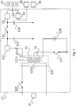
- Fig. 2 shows an operating 12 apparatus according to an embodiment of the present invention.
- the embodiment of Fig. 2 is based on the embodiment of Fig. 1 . Therefore, the aforesaid applies also to the embodiment of Fig. 2 .
- the arrangement of the operating apparatus 12 of Fig. 2 differs from the arrangement of the operating apparatus 12 of Fig. 1 in that a tapped secondary side 1212 of the transformer 112 and, particularly, a tapped secondary winding 1212 of the transformer 112 is provided.
- the tapped secondary winding 1212 is tapped for connecting the charger and the lighting device driver to the secondary winding 1212.
- Fig. 2 shows an arrangement where the second winding 1212 of the transformer 112 is tapped at a point between the ends of the second winding 1212 to provide electric energy to the charger. This construction allows avoidance of too high voltages at the one or more lighting devices.
- Fig. 3 shows an operating apparatus 12 according to an embodiment of the present invention.
- the embodiment of Fig. 3 is based on the embodiment of Fig. 1 . Therefore, the aforesaid applies also to the embodiment of Fig. 3 .
- the arrangement of the operating apparatus 12 of Fig. 3 differs from the arrangement of the operating apparatus 12 of Fig. 1 in that an isolation barrier is provided between the energy storage device 128 and the one or more lighting devices 13.
- the energy storage device 128 and the one or more lighting devices are electrically isolated from each other.
- the isolation barrier is provided, according to the present embodiment, in that the secondary side 1212 of the transformer 121 comprises at least two secondary windings 31, 32, and the charger and the lighting device driver are connected/attached to different secondary windings 31, 32.
- the lighting device driver is connected/attached to a first secondary winding 31, and the charger is connected/attached to a second secondary winding 32.
- two diodes 33, 34 or two switches 33, 34 are provided.
- the diode or switch 34 is arranged to prevent a reverse power being fed back into terminals of mains driver 35.
- the lower line, connected to the first secondary winding 31 is connected to mains driver 35 or to one or more lighting devices 13. This is visualized by a connection to an element 36, which represents the mains driver 35 or the one or more lighting devices 13.
- the present invention allows a reduction of number of components for implementing an operating apparatus 12 that is capable of being operated in the normal operation mode and the emergency operation mode.
- the operating apparatus 12 is manufacturable in a cost-effective way. Further, structure of the operating apparatus 12 is simple but at the same time very effective. Additionally, the operating apparatus 12 has a reduced size in comparison to most of known operating apparatuses 12. Hence, its implementation does not require a lot of space.
- an improved operating apparatus 12 is provided for operating one or more lighting devices 13.
Landscapes
- Business, Economics & Management (AREA)
- Emergency Management (AREA)
- Engineering & Computer Science (AREA)
- Power Engineering (AREA)
- Circuit Arrangement For Electric Light Sources In General (AREA)
Claims (10)
- Betriebseinrichtung (12), die angeordnet ist, um eine oder mehrere Beleuchtungsvorrichtungen (13) zu betreiben, wobei die Betriebseinrichtung (12) umfasst:- einen Wandler, der einen Transformator (121) umfasst, der eine Primärseite und eine Sekundärseite umfasst, wobei elektrische Energie von der Primärseite zu der Sekundärseite des Transformators (121) übertragen wird, um die eine oder die mehreren Beleuchtungsvorrichtungen zu betreiben;- eine Ladeeinheit, die eine Energiespeichervorrichtung (128) umfasst, wobei die Ladeeinheit auf der Sekundärseite des Transformators (121) angeordnet ist, mit der Sekundärwicklung (1212) des Transformators (121) verbunden ist und konfiguriert ist, um die Energiespeichervorrichtung (128) mit der elektrischen Energie zu laden, die von der Primärseite zu der Sekundärseite des Transformators (121) übertragen wird;- einen Beleuchtungsvorrichtungstreiber (122, 123, 124, 125), der auf der Sekundärseite des Transformators (121) angeordnet ist und konfiguriert ist, um der einen oder den mehreren Beleuchtungsvorrichtungen (13) die elektrische Energie zuzuführen, die von der Primärseite zu der Sekundärseite des Transformators (121) übertragen wird, wobei:- die Primärseite des Transformators (121) eine Primärwicklung (1211) umfasst und die Sekundärseite des Transformators mindestens eine Sekundärwicklung (1212) umfasst; und- die Ladeeinheit und der Beleuchtungsvorrichtungstreiber (122, 123, 124, 125) mit der mindestens einen Sekundärwicklung (1212) des Transformators (121) verbunden sind,- wobei die Ladeeinheit einen Ladeeinheitschalter (127) umfasst, der konfiguriert ist, um die Übertragung der elektrischen Energie zu der Ladeeinheit ein- oder auszuschalten, und- wobei der Beleuchtungsvorrichtungstreiber (122, 123, 124, 125) umfasst:- einen Schalter oder eine Diode (122), der/die die
Sekundärwicklung (1211) mit einem Kondensator (123) verbindet,- einen Hauptkondensator (124), der konfiguriert ist, um elektrische Energie zu der einen oder den mehreren Beleuchtungsvorrichtungen (13) zu übertragen, wenn die elektrische Energie durch die Primärseite des Transformators (121) fließt und in dem Transformator (121) gespeichert ist; und- einen Hauptkondensator-Trennschalter (125), der konfiguriert ist, um den Hauptkondensator (124) von dem Kondensator (123) zu trennen, wenn die Ladeeinheit die Energiespeichervorrichtung (128) mit der elektrischen Energie lädt, die von der Primärseite zu der Sekundärseite des Transformators (121) übertragen wird. - Betriebseinrichtung (12) nach Anspruch 1, wobei:- die Sekundärseite des Transformators (121) mindestens zwei Sekundärwicklungen (31, 32) umfasst; und- die Ladeeinheit und der Beleuchtungsvorrichtungstreiber (122, 123, 124, 125) mit unterschiedlichen Sekundärwicklungen des Transformators (121) verbunden sind.
- Betriebseinrichtung nach Anspruch 1, wobei:- die Sekundärwicklung (1212) eine abgegriffene Sekundärwicklung ist;- die Ladeeinheit und der Beleuchtungsvorrichtungstreiber (122, 123, 124, 125) mit der abgegriffenen Sekundärwicklung (1212) verbunden sind; und- die Sekundärwicklung (1212) an einem Punkt zwischen den Enden der Sekundärwicklung (1212) abgegriffen wird, um der Ladeeinheit elektrische Energie bereitzustellen.
- Betriebseinrichtung (12) nach einem der vorstehenden Ansprüche, wobei die von der Primärseite zu der Sekundärseite des Transformators (121) übertragene elektrische Energie selektiv und/oder abwechselnd der Ladeeinheit oder dem Beleuchtungsvorrichtungstreiber (122, 123, 124, 125) bereitgestellt wird.
- Betriebseinrichtung (12) nach einem der vorstehenden Ansprüche, wobei die Ladeeinheit und der Beleuchtungsvorrichtungstreiber (122, 123, 124, 125) selektiv und/oder abwechselnd betrieben werden.
- Betriebseinrichtung (12) nach einem der vorstehenden Ansprüche, wobei:- wenn eine Beleuchtungsvorrichtungsspannung, die durch die eine oder die mehreren Beleuchtungsvorrichtungen (13) fließt, größer als eine Energiespeichervorrichtungsspannung ist, die Betriebseinrichtung (12) konfiguriert ist, um die eine oder die mehreren Beleuchtungsvorrichtungen (13) mit einem negativen Anschluss der Energiespeichervorrichtung (128) zu verbinden; und- wenn die Beleuchtungsvorrichtungsspannung, die durch die eine oder die mehreren Beleuchtungsvorrichtungen (13) fließt, kleiner als die Energiespeichervorrichtungsspannung ist, die Betriebseinrichtung (12) konfiguriert ist, um die eine oder die mehreren Beleuchtungsvorrichtungen (13) mit einem positiven Anschluss der Energiespeichervorrichtung (128) zu verbinden.
- Betriebseinrichtung (12) nach einem der vorstehenden Ansprüche, wobei die Betriebseinrichtung (12) eine Isolationsbarriere zwischen der einen oder den mehreren Beleuchtungsvorrichtungen (13) und der Energiespeichereinrichtung (128) umfasst.
- Betriebseinrichtung (12) nach einem der vorstehenden Ansprüche, wobei die Betriebseinrichtung (12) ein Sperrwandler ist und der Transformator (121) ein Transformator des Sperrwandlers ist.
- Betriebseinrichtung (12) nach einem der vorstehenden Ansprüche, wobei die Betriebseinrichtung (12) einen oder mehrere Ausgänge (126) umfasst, mit denen die eine oder die mehreren Beleuchtungsvorrichtungen (13) direkt oder indirekt verbindbar sind und die dazu konfiguriert sind, der einen oder den mehreren Beleuchtungsvorrichtungen (13) die elektrische Energie bereitzustellen.
- Betriebseinrichtung (12) nach einem der vorstehenden Ansprüche, wobei:die Betriebseinrichtung (12) in einem Normalbetriebsmodus und in einem Notbetriebsmodus betrieben wird;in dem Normalbetriebsmodus die elektrische Energie der einen oder den mehreren Beleuchtungsvorrichtungen (13) über den Beleuchtungsvorrichtungstreiber (122, 123, 124, 125) bereitgestellt wird; undin dem Notbetriebsmodus die elektrische Energie der einen oder den mehreren Beleuchtungsvorrichtungen (13) über die Energiespeichervorrichtung (128) bereitgestellt wird.
Applications Claiming Priority (1)
| Application Number | Priority Date | Filing Date | Title |
|---|---|---|---|
| GB1700927.5A GB2558674B (en) | 2017-01-10 | 2017-01-10 | Apparatus for operating one or more lighting devices |
Publications (2)
| Publication Number | Publication Date |
|---|---|
| EP3346802A1 EP3346802A1 (de) | 2018-07-11 |
| EP3346802B1 true EP3346802B1 (de) | 2020-11-18 |
Family
ID=60888323
Family Applications (1)
| Application Number | Title | Priority Date | Filing Date |
|---|---|---|---|
| EP18150018.2A Active EP3346802B1 (de) | 2017-01-10 | 2018-01-02 | Vorrichtung zum betreiben einer oder mehrerer beleuchtungsvorrichtungen |
Country Status (2)
| Country | Link |
|---|---|
| EP (1) | EP3346802B1 (de) |
| GB (1) | GB2558674B (de) |
Family Cites Families (10)
| Publication number | Priority date | Publication date | Assignee | Title |
|---|---|---|---|---|
| DE102006030655A1 (de) * | 2006-04-21 | 2007-10-25 | Tridonicatco Gmbh & Co. Kg | Notlichtgerät zum Betreiben einer Lichtquelle, insbesondere einer LED |
| US8575787B2 (en) * | 2009-01-26 | 2013-11-05 | Exelon Generation Company, Llc | Emergency lighting methods and systems |
| AU2012277331B2 (en) * | 2011-06-30 | 2017-01-19 | Schneider Electric Industries Sas | Dual power SMPS for a modular lighting system |
| DE102011080996B4 (de) * | 2011-08-16 | 2024-02-15 | Tridonic Gmbh & Co Kg | Betrieb eines Leuchtmittels mit autonomem Energiespeicher |
| US9882497B2 (en) * | 2012-09-28 | 2018-01-30 | Microchip Technology Incorporated | Soft switching synchronous quasi resonant converter |
| WO2015015356A1 (en) * | 2013-08-01 | 2015-02-05 | Koninklijke Philips N.V. | Methods, apparatus and system for self-powered lighting |
| EP3032696B1 (de) * | 2014-12-10 | 2018-10-03 | Tridonic GmbH & Co KG | Notbeleuchtungseinheit |
| GB2535808B (en) * | 2015-02-25 | 2021-08-25 | Tridonic Gmbh & Co Kg | Voltage supply unit and method for operating a light source |
| CN105323923B (zh) * | 2015-10-27 | 2018-11-30 | 浙江生辉照明有限公司 | Led智能控制电路及led照明装置 |
| CN205812467U (zh) * | 2016-07-21 | 2016-12-14 | 宁波奇驰照明灯具有限公司 | Led应急控制电路 |
-
2017
- 2017-01-10 GB GB1700927.5A patent/GB2558674B/en active Active
-
2018
- 2018-01-02 EP EP18150018.2A patent/EP3346802B1/de active Active
Non-Patent Citations (1)
| Title |
|---|
| None * |
Also Published As
| Publication number | Publication date |
|---|---|
| GB2558674A (en) | 2018-07-18 |
| GB2558674B (en) | 2022-01-19 |
| EP3346802A1 (de) | 2018-07-11 |
Similar Documents
| Publication | Publication Date | Title |
|---|---|---|
| CN100420136C (zh) | 开关电源装置 | |
| US7812572B2 (en) | Device and method for charge equalization of series-connected individual cells of an energy accumulator | |
| US20090067200A1 (en) | Device and method for equalizing the charges of individual, series-connected cells of an energy storage device | |
| US8772963B2 (en) | Device for supplying uninterruptible power | |
| US20200395840A1 (en) | Flexible bootstrapping for power electronics circuits | |
| US9917522B2 (en) | Power control apparatus for sub-module of MMC converter | |
| CN102474190B (zh) | 用于对蓄电池组充电的充电装置 | |
| US20120087154A1 (en) | Voltage supply device for a load | |
| JP2011034687A (ja) | 配線装置、スイッチ、プラグおよびコンセント | |
| KR102005880B1 (ko) | Dc-dc 변환 시스템 | |
| EP3603344B1 (de) | Elektronische schaltung zum antrieb eines leuchtdiodenstrangs | |
| JP2017225328A (ja) | 直流源を保護するための装置及び方法 | |
| CN112187056B (zh) | 电力供给系统和直流-直流转换机 | |
| US8779837B2 (en) | Load control device | |
| US9025302B2 (en) | Ionizer | |
| EP2372740A2 (de) | Treiberschaltung für ein Relais | |
| EP3346802B1 (de) | Vorrichtung zum betreiben einer oder mehrerer beleuchtungsvorrichtungen | |
| US9041382B2 (en) | Power-supply circuit for DC appliance | |
| KR100963024B1 (ko) | 플라이백 컨버터용 동기정류기 구동회로 | |
| US9600012B2 (en) | Internal power supply of a device | |
| EP3596801B1 (de) | Notumsetzer-ausgangsschaltung | |
| JP2015050825A (ja) | 放電制御装置 | |
| US20160043640A1 (en) | Switch mode power supply with a cascode circuit | |
| JP2022061081A (ja) | 非常用照明装置 | |
| EP3046215B1 (de) | Vorrichtung zur unterbrechungsfreien Stromversorgung für elektrische Mittelspannungsinstallationen im Außenbereich |
Legal Events
| Date | Code | Title | Description |
|---|---|---|---|
| PUAI | Public reference made under article 153(3) epc to a published international application that has entered the european phase |
Free format text: ORIGINAL CODE: 0009012 |
|
| STAA | Information on the status of an ep patent application or granted ep patent |
Free format text: STATUS: THE APPLICATION HAS BEEN PUBLISHED |
|
| AK | Designated contracting states |
Kind code of ref document: A1 Designated state(s): AL AT BE BG CH CY CZ DE DK EE ES FI FR GB GR HR HU IE IS IT LI LT LU LV MC MK MT NL NO PL PT RO RS SE SI SK SM TR |
|
| AX | Request for extension of the european patent |
Extension state: BA ME |
|
| STAA | Information on the status of an ep patent application or granted ep patent |
Free format text: STATUS: REQUEST FOR EXAMINATION WAS MADE |
|
| 17P | Request for examination filed |
Effective date: 20181122 |
|
| RBV | Designated contracting states (corrected) |
Designated state(s): AL AT BE BG CH CY CZ DE DK EE ES FI FR GB GR HR HU IE IS IT LI LT LU LV MC MK MT NL NO PL PT RO RS SE SI SK SM TR |
|
| STAA | Information on the status of an ep patent application or granted ep patent |
Free format text: STATUS: EXAMINATION IS IN PROGRESS |
|
| 17Q | First examination report despatched |
Effective date: 20190918 |
|
| REG | Reference to a national code |
Ref country code: DE Ref legal event code: R079 Ref document number: 602018009688 Country of ref document: DE Free format text: PREVIOUS MAIN CLASS: H05B0033080000 Ipc: H05B0045000000 |
|
| GRAP | Despatch of communication of intention to grant a patent |
Free format text: ORIGINAL CODE: EPIDOSNIGR1 |
|
| STAA | Information on the status of an ep patent application or granted ep patent |
Free format text: STATUS: GRANT OF PATENT IS INTENDED |
|
| RIC1 | Information provided on ipc code assigned before grant |
Ipc: H05B 45/00 20200101AFI20200616BHEP Ipc: H05B 45/50 20200101ALI20200616BHEP Ipc: H05B 45/37 20200101ALI20200616BHEP |
|
| INTG | Intention to grant announced |
Effective date: 20200710 |
|
| GRAS | Grant fee paid |
Free format text: ORIGINAL CODE: EPIDOSNIGR3 |
|
| GRAA | (expected) grant |
Free format text: ORIGINAL CODE: 0009210 |
|
| STAA | Information on the status of an ep patent application or granted ep patent |
Free format text: STATUS: THE PATENT HAS BEEN GRANTED |
|
| AK | Designated contracting states |
Kind code of ref document: B1 Designated state(s): AL AT BE BG CH CY CZ DE DK EE ES FI FR GB GR HR HU IE IS IT LI LT LU LV MC MK MT NL NO PL PT RO RS SE SI SK SM TR |
|
| REG | Reference to a national code |
Ref country code: GB Ref legal event code: FG4D |
|
| REG | Reference to a national code |
Ref country code: CH Ref legal event code: EP |
|
| REG | Reference to a national code |
Ref country code: IE Ref legal event code: FG4D |
|
| REG | Reference to a national code |
Ref country code: DE Ref legal event code: R096 Ref document number: 602018009688 Country of ref document: DE |
|
| REG | Reference to a national code |
Ref country code: AT Ref legal event code: REF Ref document number: 1337163 Country of ref document: AT Kind code of ref document: T Effective date: 20201215 |
|
| REG | Reference to a national code |
Ref country code: AT Ref legal event code: MK05 Ref document number: 1337163 Country of ref document: AT Kind code of ref document: T Effective date: 20201118 |
|
| REG | Reference to a national code |
Ref country code: NL Ref legal event code: MP Effective date: 20201118 |
|
| PG25 | Lapsed in a contracting state [announced via postgrant information from national office to epo] |
Ref country code: FI Free format text: LAPSE BECAUSE OF FAILURE TO SUBMIT A TRANSLATION OF THE DESCRIPTION OR TO PAY THE FEE WITHIN THE PRESCRIBED TIME-LIMIT Effective date: 20201118 Ref country code: RS Free format text: LAPSE BECAUSE OF FAILURE TO SUBMIT A TRANSLATION OF THE DESCRIPTION OR TO PAY THE FEE WITHIN THE PRESCRIBED TIME-LIMIT Effective date: 20201118 Ref country code: PT Free format text: LAPSE BECAUSE OF FAILURE TO SUBMIT A TRANSLATION OF THE DESCRIPTION OR TO PAY THE FEE WITHIN THE PRESCRIBED TIME-LIMIT Effective date: 20210318 Ref country code: GR Free format text: LAPSE BECAUSE OF FAILURE TO SUBMIT A TRANSLATION OF THE DESCRIPTION OR TO PAY THE FEE WITHIN THE PRESCRIBED TIME-LIMIT Effective date: 20210219 Ref country code: NO Free format text: LAPSE BECAUSE OF FAILURE TO SUBMIT A TRANSLATION OF THE DESCRIPTION OR TO PAY THE FEE WITHIN THE PRESCRIBED TIME-LIMIT Effective date: 20210218 |
|
| PG25 | Lapsed in a contracting state [announced via postgrant information from national office to epo] |
Ref country code: AT Free format text: LAPSE BECAUSE OF FAILURE TO SUBMIT A TRANSLATION OF THE DESCRIPTION OR TO PAY THE FEE WITHIN THE PRESCRIBED TIME-LIMIT Effective date: 20201118 Ref country code: SE Free format text: LAPSE BECAUSE OF FAILURE TO SUBMIT A TRANSLATION OF THE DESCRIPTION OR TO PAY THE FEE WITHIN THE PRESCRIBED TIME-LIMIT Effective date: 20201118 Ref country code: LV Free format text: LAPSE BECAUSE OF FAILURE TO SUBMIT A TRANSLATION OF THE DESCRIPTION OR TO PAY THE FEE WITHIN THE PRESCRIBED TIME-LIMIT Effective date: 20201118 Ref country code: PL Free format text: LAPSE BECAUSE OF FAILURE TO SUBMIT A TRANSLATION OF THE DESCRIPTION OR TO PAY THE FEE WITHIN THE PRESCRIBED TIME-LIMIT Effective date: 20201118 Ref country code: IS Free format text: LAPSE BECAUSE OF FAILURE TO SUBMIT A TRANSLATION OF THE DESCRIPTION OR TO PAY THE FEE WITHIN THE PRESCRIBED TIME-LIMIT Effective date: 20210318 Ref country code: BG Free format text: LAPSE BECAUSE OF FAILURE TO SUBMIT A TRANSLATION OF THE DESCRIPTION OR TO PAY THE FEE WITHIN THE PRESCRIBED TIME-LIMIT Effective date: 20210218 |
|
| REG | Reference to a national code |
Ref country code: LT Ref legal event code: MG9D |
|
| PG25 | Lapsed in a contracting state [announced via postgrant information from national office to epo] |
Ref country code: HR Free format text: LAPSE BECAUSE OF FAILURE TO SUBMIT A TRANSLATION OF THE DESCRIPTION OR TO PAY THE FEE WITHIN THE PRESCRIBED TIME-LIMIT Effective date: 20201118 |
|
| PG25 | Lapsed in a contracting state [announced via postgrant information from national office to epo] |
Ref country code: LT Free format text: LAPSE BECAUSE OF FAILURE TO SUBMIT A TRANSLATION OF THE DESCRIPTION OR TO PAY THE FEE WITHIN THE PRESCRIBED TIME-LIMIT Effective date: 20201118 Ref country code: EE Free format text: LAPSE BECAUSE OF FAILURE TO SUBMIT A TRANSLATION OF THE DESCRIPTION OR TO PAY THE FEE WITHIN THE PRESCRIBED TIME-LIMIT Effective date: 20201118 Ref country code: CZ Free format text: LAPSE BECAUSE OF FAILURE TO SUBMIT A TRANSLATION OF THE DESCRIPTION OR TO PAY THE FEE WITHIN THE PRESCRIBED TIME-LIMIT Effective date: 20201118 Ref country code: SM Free format text: LAPSE BECAUSE OF FAILURE TO SUBMIT A TRANSLATION OF THE DESCRIPTION OR TO PAY THE FEE WITHIN THE PRESCRIBED TIME-LIMIT Effective date: 20201118 Ref country code: SK Free format text: LAPSE BECAUSE OF FAILURE TO SUBMIT A TRANSLATION OF THE DESCRIPTION OR TO PAY THE FEE WITHIN THE PRESCRIBED TIME-LIMIT Effective date: 20201118 Ref country code: RO Free format text: LAPSE BECAUSE OF FAILURE TO SUBMIT A TRANSLATION OF THE DESCRIPTION OR TO PAY THE FEE WITHIN THE PRESCRIBED TIME-LIMIT Effective date: 20201118 |
|
| REG | Reference to a national code |
Ref country code: DE Ref legal event code: R097 Ref document number: 602018009688 Country of ref document: DE |
|
| PG25 | Lapsed in a contracting state [announced via postgrant information from national office to epo] |
Ref country code: DK Free format text: LAPSE BECAUSE OF FAILURE TO SUBMIT A TRANSLATION OF THE DESCRIPTION OR TO PAY THE FEE WITHIN THE PRESCRIBED TIME-LIMIT Effective date: 20201118 Ref country code: MC Free format text: LAPSE BECAUSE OF FAILURE TO SUBMIT A TRANSLATION OF THE DESCRIPTION OR TO PAY THE FEE WITHIN THE PRESCRIBED TIME-LIMIT Effective date: 20201118 |
|
| REG | Reference to a national code |
Ref country code: CH Ref legal event code: PL |
|
| PLBE | No opposition filed within time limit |
Free format text: ORIGINAL CODE: 0009261 |
|
| STAA | Information on the status of an ep patent application or granted ep patent |
Free format text: STATUS: NO OPPOSITION FILED WITHIN TIME LIMIT |
|
| PG25 | Lapsed in a contracting state [announced via postgrant information from national office to epo] |
Ref country code: LU Free format text: LAPSE BECAUSE OF NON-PAYMENT OF DUE FEES Effective date: 20210102 |
|
| REG | Reference to a national code |
Ref country code: BE Ref legal event code: MM Effective date: 20210131 |
|
| 26N | No opposition filed |
Effective date: 20210819 |
|
| PG25 | Lapsed in a contracting state [announced via postgrant information from national office to epo] |
Ref country code: IT Free format text: LAPSE BECAUSE OF FAILURE TO SUBMIT A TRANSLATION OF THE DESCRIPTION OR TO PAY THE FEE WITHIN THE PRESCRIBED TIME-LIMIT Effective date: 20201118 Ref country code: NL Free format text: LAPSE BECAUSE OF FAILURE TO SUBMIT A TRANSLATION OF THE DESCRIPTION OR TO PAY THE FEE WITHIN THE PRESCRIBED TIME-LIMIT Effective date: 20201118 Ref country code: AL Free format text: LAPSE BECAUSE OF FAILURE TO SUBMIT A TRANSLATION OF THE DESCRIPTION OR TO PAY THE FEE WITHIN THE PRESCRIBED TIME-LIMIT Effective date: 20201118 |
|
| PG25 | Lapsed in a contracting state [announced via postgrant information from national office to epo] |
Ref country code: LI Free format text: LAPSE BECAUSE OF NON-PAYMENT OF DUE FEES Effective date: 20210131 Ref country code: CH Free format text: LAPSE BECAUSE OF NON-PAYMENT OF DUE FEES Effective date: 20210131 Ref country code: SI Free format text: LAPSE BECAUSE OF FAILURE TO SUBMIT A TRANSLATION OF THE DESCRIPTION OR TO PAY THE FEE WITHIN THE PRESCRIBED TIME-LIMIT Effective date: 20201118 |
|
| PG25 | Lapsed in a contracting state [announced via postgrant information from national office to epo] |
Ref country code: IE Free format text: LAPSE BECAUSE OF NON-PAYMENT OF DUE FEES Effective date: 20210102 Ref country code: ES Free format text: LAPSE BECAUSE OF FAILURE TO SUBMIT A TRANSLATION OF THE DESCRIPTION OR TO PAY THE FEE WITHIN THE PRESCRIBED TIME-LIMIT Effective date: 20201118 |
|
| PG25 | Lapsed in a contracting state [announced via postgrant information from national office to epo] |
Ref country code: IS Free format text: LAPSE BECAUSE OF FAILURE TO SUBMIT A TRANSLATION OF THE DESCRIPTION OR TO PAY THE FEE WITHIN THE PRESCRIBED TIME-LIMIT Effective date: 20210318 |
|
| PG25 | Lapsed in a contracting state [announced via postgrant information from national office to epo] |
Ref country code: BE Free format text: LAPSE BECAUSE OF NON-PAYMENT OF DUE FEES Effective date: 20210131 |
|
| PG25 | Lapsed in a contracting state [announced via postgrant information from national office to epo] |
Ref country code: CY Free format text: LAPSE BECAUSE OF FAILURE TO SUBMIT A TRANSLATION OF THE DESCRIPTION OR TO PAY THE FEE WITHIN THE PRESCRIBED TIME-LIMIT Effective date: 20201118 |
|
| P01 | Opt-out of the competence of the unified patent court (upc) registered |
Effective date: 20230530 |
|
| PG25 | Lapsed in a contracting state [announced via postgrant information from national office to epo] |
Ref country code: HU Free format text: LAPSE BECAUSE OF FAILURE TO SUBMIT A TRANSLATION OF THE DESCRIPTION OR TO PAY THE FEE WITHIN THE PRESCRIBED TIME-LIMIT; INVALID AB INITIO Effective date: 20180102 |
|
| PG25 | Lapsed in a contracting state [announced via postgrant information from national office to epo] |
Ref country code: MK Free format text: LAPSE BECAUSE OF FAILURE TO SUBMIT A TRANSLATION OF THE DESCRIPTION OR TO PAY THE FEE WITHIN THE PRESCRIBED TIME-LIMIT Effective date: 20201118 |
|
| PG25 | Lapsed in a contracting state [announced via postgrant information from national office to epo] |
Ref country code: MT Free format text: LAPSE BECAUSE OF FAILURE TO SUBMIT A TRANSLATION OF THE DESCRIPTION OR TO PAY THE FEE WITHIN THE PRESCRIBED TIME-LIMIT Effective date: 20201118 |
|
| REG | Reference to a national code |
Ref country code: DE Ref legal event code: R084 Ref document number: 602018009688 Country of ref document: DE |
|
| PG25 | Lapsed in a contracting state [announced via postgrant information from national office to epo] |
Ref country code: TR Free format text: LAPSE BECAUSE OF FAILURE TO SUBMIT A TRANSLATION OF THE DESCRIPTION OR TO PAY THE FEE WITHIN THE PRESCRIBED TIME-LIMIT Effective date: 20201118 |
|
| PGFP | Annual fee paid to national office [announced via postgrant information from national office to epo] |
Ref country code: GB Payment date: 20260126 Year of fee payment: 9 |
|
| PGFP | Annual fee paid to national office [announced via postgrant information from national office to epo] |
Ref country code: DE Payment date: 20260127 Year of fee payment: 9 |
|
| PGFP | Annual fee paid to national office [announced via postgrant information from national office to epo] |
Ref country code: FR Payment date: 20260126 Year of fee payment: 9 |