EP3346894B1 - Buse de sol - Google Patents
Buse de sol Download PDFInfo
- Publication number
- EP3346894B1 EP3346894B1 EP15760195.6A EP15760195A EP3346894B1 EP 3346894 B1 EP3346894 B1 EP 3346894B1 EP 15760195 A EP15760195 A EP 15760195A EP 3346894 B1 EP3346894 B1 EP 3346894B1
- Authority
- EP
- European Patent Office
- Prior art keywords
- floor nozzle
- arm
- longitudinal side
- floor
- moveable
- Prior art date
- Legal status (The legal status is an assumption and is not a legal conclusion. Google has not performed a legal analysis and makes no representation as to the accuracy of the status listed.)
- Active
Links
Images


Classifications
-
- A—HUMAN NECESSITIES
- A47—FURNITURE; DOMESTIC ARTICLES OR APPLIANCES; COFFEE MILLS; SPICE MILLS; SUCTION CLEANERS IN GENERAL
- A47L—DOMESTIC WASHING OR CLEANING; SUCTION CLEANERS IN GENERAL
- A47L9/00—Details or accessories of suction cleaners, e.g. mechanical means for controlling the suction or for effecting pulsating action; Storing devices specially adapted to suction cleaners or parts thereof; Carrying-vehicles specially adapted for suction cleaners
- A47L9/02—Nozzles
- A47L9/06—Nozzles with fixed, e.g. adjustably fixed brushes or the like
- A47L9/0633—Nozzles with fixed, e.g. adjustably fixed brushes or the like with retractable brushes, combs, lips or pads
- A47L9/064—Nozzles with fixed, e.g. adjustably fixed brushes or the like with retractable brushes, combs, lips or pads actuating means therefor
- A47L9/0653—Nozzles with fixed, e.g. adjustably fixed brushes or the like with retractable brushes, combs, lips or pads actuating means therefor with mechanical actuation, e.g. using a lever
-
- A—HUMAN NECESSITIES
- A47—FURNITURE; DOMESTIC ARTICLES OR APPLIANCES; COFFEE MILLS; SPICE MILLS; SUCTION CLEANERS IN GENERAL
- A47L—DOMESTIC WASHING OR CLEANING; SUCTION CLEANERS IN GENERAL
- A47L9/00—Details or accessories of suction cleaners, e.g. mechanical means for controlling the suction or for effecting pulsating action; Storing devices specially adapted to suction cleaners or parts thereof; Carrying-vehicles specially adapted for suction cleaners
- A47L9/02—Nozzles
- A47L9/06—Nozzles with fixed, e.g. adjustably fixed brushes or the like
- A47L9/0633—Nozzles with fixed, e.g. adjustably fixed brushes or the like with retractable brushes, combs, lips or pads
Definitions
- the invention relates to a floor nozzle for a vacuum cleaner, comprising a floor body, at least one suction mouth, which is arranged on the floor body and can be fluidly connected or connected to a suction unit, and a contact device, which can be applied to a surface to be cleaned and which has the at least one Surrounds the suction mouth, wherein when the contact device is placed on the surface to be cleaned, a suction chamber is formed between the surface to be cleaned and the contact device, into which the suction mouth opens, and wherein the contact device has openings in the suction chamber on at least one side, and the at least one one side with the openings is assigned at least one movable bar which has at least two positions, a first position being a closed position in which the openings are covered and a second position being a release position in which the openings are released.
- the EP 2 875 765 A1 discloses a suction nozzle for a vacuum cleaner, the suction nozzle having a suction channel and at least a first section for enclosing a suction area of the suction nozzle.
- the first section has a circumferential sealing area for sealing the suction area against a surface to be processed with the vacuum cleaner.
- a cleaning head for a floor cleaning device which comprises a suction housing with a suction channel opening into suction openings and a carrying part holding the suction housing.
- the suction housing can be displaced in relation to the support part against the feed direction and the cleaning head has gear means for converting the displacement movement of the suction housing into a lifting and lowering movement of wiper lips.
- a nozzle for a vacuum cleaner with a chassis which has a rear chassis section with at least one roller and a front section protruding in the suction direction for connection of a suction head.
- a suction head is tiltably mounted on the front section of the chassis about a horizontal axis.
- a suction head for household canister vacuum cleaners which has a sliding zone which is rigidly or tiltably attached to an upper housing part and has a suction mouth extending transversely to the working direction.
- the invention has for its object to provide a floor nozzle of the type mentioned, which has advanced functions.
- a movement mechanism is provided for the at least one movable bar, which couples the position of the at least one movable bar to a stroke of the floor nozzle on the surface to be cleaned, and in that the movement mechanism has a first arm which is pivotally mounted to the floor body and on which the at least one movable bar is arranged, wherein a pivoting movement of the first arm causes a movement of the at least one movable bar.
- the openings on the contact device serve to allow dirt particles from an outside space outside the suction space to pass through the openings into the suction space and then to be suctioned off.
- the openings are released in order to allow dirt particles to pass through the contact device into the suction chamber.
- the openings are covered in the closed position. This allows the suction chamber to be sealed well and high suction power is provided.
- the first position or the second position can be set via the movement mechanism.
- an operator can set, by means of a corresponding stroke, whether he wants to have an increased suction force, in particular for a crack extraction, or whether he wants to open the openings in a normal suction operation in order to enable a high degree of dirt absorption of dirt particles on the surface to be cleaned.
- the movement mechanism is designed such that it couples the position of the at least one movable bar to a stroke direction of the floor nozzle on the surface to be cleaned.
- a coupling to a forward stroke direction and to a reverse stroke direction is provided. If the openings for a forward stroke movement are released, then a "normal" dirt pick-up is possible. If, for example, the openings are covered for a backward lifting movement, then cracks and the like can be effectively sucked out.
- the corresponding function is set automatically.
- the contact device has a first longitudinal side, a second longitudinal side spaced apart from the first longitudinal side, a first transverse side which is arranged between the first longitudinal side and the second longitudinal side, and a second transverse side spaced apart from the first transverse side which lies between the first longitudinal side and the second long side is arranged, the openings being arranged on the first long side and / or the second long side and the at least one movable bar being associated with the first long side and / or the second long side.
- the long sides and the short sides are on the corresponding ones Longitudinal and transverse elements formed. They form a wall for the suction space. This enables an effective suction result to be achieved.
- a forward stroke of the floor nozzle In the case of a forward stroke of the floor nozzle, it is moved in particular in a direction parallel to a direction from the second long side to the first long side, and in the event of a backward stroke of the floor nozzle it is moved in a direction parallel to a direction from the first long side to the second long side , wherein the first longitudinal side is assigned the at least one movable bar and the movement mechanism is designed such that the at least one movable bar is in the release position during the forward stroke and the at least one movable bar is in the closed position during the reverse stroke.
- This results in the at least one movable bar being brought and held in the release position or in the closed position depending on the forward stroke or reverse stroke. This results in an expanded functionality, with an operator simply specifying a switchover option by changing the stroke direction.
- the at least one movable bar is positioned between the first long side and a front wall of the floor nozzle adjacent to the first long side and / or positioned between the second long side and a rear wall of the floor nozzle adjacent to the second long side.
- the at least one movable bar is positioned adjacent to the long side with the openings to allow effective coverage.
- the contact device has one or more brush strips and / or one or more lip strips with one or more elastic lip elements.
- the at least one movable bar is designed as a lip bar with one or more elastic lip elements or brush bar.
- the movement mechanism has a first arm which is pivotally mounted to the floor body (and is, for example, mounted on the floor body) and on which the at least one movable bar is arranged, wherein a pivoting movement of the first arm causes a movement of the at least one movable bar.
- the first arm holds the at least one movable bar and enables a change of position or holding in the first position or the second position.
- a second arm is articulated to the first arm, the second arm being coupled to a device of the floor nozzle which is movable to the floor body, a position of this device to the floor body being dependent on the Stroke of the floor nozzle on the surface to be cleaned.
- the stroke of the floor nozzle on the surface to be cleaned, and in particular the stroke direction determines the position of the device relative to the floor body. This in turn determines the position of the second arm.
- the position of the second arm in turn determines whether the second position or the first position of the at least one movable bar is present.
- the device movable to the floor body detects which stroke is present and in particular which stroke direction is present.
- the position of the movable device relative to the floor body is different.
- the relative position of the second arm to the floor body is also different.
- the position of the second arm to the floor body determines the position of the first arm. This in turn determines whether the at least one movable bar is in its second position or in its first position.
- a change in the stroke direction causes the device to move, the movable bar then being brought into its new position (the second position starting from the first position or the first position starting from the second position) via the second arm and the first arm.
- the device movable to the floor body comprises a roller device, and in particular that the second arm is coupled to the movable device in the area of the roller device.
- the roller device can be "detected" in a simple manner which stroke direction is present, and this detection result can then be easily connected to the first arm and by coupling the second arm, which is preferably coupled to the movable device in the area of the roller device thus transferred to the at least one movable bar.
- first arm and the second arm are articulated to one another via a guide device which enables a relative displacement between the first arm and the second arm, the guide device in particular comprising a recess-pin guide (link guide).
- the guide device in particular comprising a recess-pin guide (link guide).
- the guide device defines the release position and, in particular, the fact that a pin of the recess-pin guide bears against a boundary of a recess of the recess-pin guide defines the release position. This makes it easy to define the excellent release position as the second position.
- At least one tilt joint is provided, which has a tilt axis that is parallel to a pivot axis of the first arm. This means that the floor nozzle can be placed well against a surface to be cleaned for a good suction result.
- an end face of the at least one movable bar facing the surface to be cleaned lies at least approximately in one plane with a corresponding end face of the contact device.
- a locking device is provided, by means of which the first position and / or the second position can be fixed.
- an automatic change in a predetermined position of the at least one movable bar can be blocked as a function of a stroke of the floor nozzle. This makes it possible to "permanently” secure the first position and / or the second position. The movement of the at least one bar is blocked by the locking device.
- the locking device comprises a switch.
- An operator can then use a switch to set whether he wants automatic operation by setting the first position or the second position of the at least one movable bar depending on the stroke movement of the floor nozzle, or whether he wants a fixed position of the movable bar independently of that Stroke of the floor nozzle.
- the locking device comprises at least one movable element, in particular in the form of a pin element, which engages on a recess-pin guide, the movement mechanism having a first arm which is pivotally mounted to the floor body and on which the at least one movable bar is arranged wherein a pivotal movement of the first arm causes movement of the at least one ledge, and wherein a second arm is articulated to the first arm and the first arm and the second arm are articulated to one another via a recess-pin guide, which have a relative displacement between the first arm and the second arm.
- the element can in particular engage in the recess and this relative displaceability lock and thus define a specific position of the first arm and thus in turn the at least one movable bar.
- Said at least one movable element (in particular pin element) is advantageously coupled to a switch that can be operated by an operator.
- the position of the pin element is then determined by a corresponding switch position, and in turn it is set whether the at least one movable bar is fixed, that is to say made immobile, or whether the mobility is released.
- the inventive design with the at least one movable bar can be integrated into the floor nozzle, which in the PCT / EP2015 / 054764 from March 6, 2015. Reference is expressly made to this document.
- the elements described in the international patent application mentioned can be integrated into the floor nozzle according to the invention.
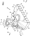
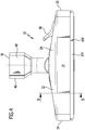
- An embodiment of a floor nozzle which in the Figures 1 to 6 and is designated there by 10, comprises a housing 12.
- the housing 12 has a front wall 14, a rear wall 16 which is spaced apart from the front wall 14, a first side wall 18, and a second side wall 20 which is spaced apart from the first side wall 18.
- the first side wall 18 is connected to the front wall 14 and the rear wall 16.
- the second side wall 20 is connected to the front wall 14 and the rear wall 16.
- the housing 12 also has a housing cover 22.
- the housing cover 22 defines an upper side 24 of the housing 12.
- the housing 12 has an underside 26 opposite the top 24 ( Figures 3 , 5 , 6 ) on.
- a housing interior 28 is formed between the front wall 14, the rear wall 16, the first side wall 18, the second side wall 20 and the housing cover 22. This housing interior 28 is laterally covered by the side walls 18, 20, covered to the front by the front wall 14, covered to the rear by the rear wall 16 and upwards by the housing cover 22.
- the housing 12 has at least approximately a cuboid shape.
- a connection 30 for an intake manifold is assigned to the housing 12.
- a suction pipe can be inserted into this connection 30 and a fluid-effective connection to a suction unit 31 of a vacuum cleaner can thereby be established.
- the floor nozzle 10 can also be mechanically fixed to the corresponding suction pipe via the connection 30.
- a roller device 32 is arranged on the housing 12 in the region of the rear wall 16 outside the housing 12.
- the roller device 32 comprises one or more rollers, by means of which the floor nozzle 10 can be supported on a floor surface.
- the roller or rollers of the roller device 32 are rotatable about an axis 34.
- the axis 34 is aligned parallel to the front wall 14.
- connection 30 On a holder 36 for the roller or rollers of the roller device 32 is a web 38, on which in turn the connection 30 is seated.
- the connection 30 comprises a connection body 40 in which a recess 42 is formed.
- the recess 42 is cylindrical.
- the suction pipe can be inserted and fixed in it.
- the recess 42 is formed, for example, in a pipe section 44 seated on the connecting body 40.
- a flexible hose 46 is connected to the pipe section 44 and leads from the pipe section 44 into the housing interior 28 to an orifice piece 47.
- connection body 40 has a side 48 which is designed such that a housing of a vacuum cleaner, on which the suction tube is positioned outside the housing, can be placed in a specific position and in particular in a standing position.
- the side 48 forms a contact surface for this housing of the vacuum cleaner.
- the holder 36 for the roller device 32 is firmly connected to the connector body 40.
- a tilt joint 52 is formed on the holder 36.
- This tilting joint 52 is formed, for example, in that the holder 36 has a cylindrical region 54 on which an element 56 is pivotably seated, on which in turn the web 38 is firmly seated.
- the element 56 is guided orbitally on the cylindrical region 54.
- An axis of the cylindrical portion 54 coincides with the axis 34 of the roller device 32 for rotational movement of the roller or rollers. Accordingly, a tilt axis 58 is formed, which coincides with the axis 34.
- channels 60 which run between the top 24 and the bottom 26.
- the channels 60 form flow channels. They are formed, for example, by grooves in the front wall 14.
- the channels 60 are oriented in particular perpendicularly with respect to a lower edge 62 of the front wall 14 on the underside 26.
- a forward stroke direction 64 (slide direction) is provided ( Figures 1 , 3rd , 6 ), which corresponds to the direction from the rear wall 16 to the front wall 14.
- a backward stroke direction 66 (pulling direction) is also provided, which is opposite to the forward stroke direction 64.
- FIG 1 the floor nozzle is shown in a "storage position" (parking position), in which the pipe section 44 is oriented perpendicular or approximately perpendicular to the axis 34 with a pipe axis.
- a "storage position” parking position
- the pipe section 44 is oriented perpendicular or approximately perpendicular to the axis 34 with a pipe axis.
- Working positions of the floor nozzle 10 are shown, in which the pipe axis of the pipe section 44 lies at an acute angle to the axis 34 and also to a surface 72 to be cleaned.
- a floor body 68 is arranged in the housing interior 28.
- the bottom body 68 is in particular plate-shaped.
- the bottom body 68 is fixedly arranged in the housing interior 28, wherein it can be formed in several parts with parts that are movable with respect to one another or parts that are immovable with respect to one another.
- the mouthpiece 47 is formed on the base body 68 or is arranged on the base body 68.
- a suction mouth 70 is formed on the mouthpiece 47, through which dirt particles can be sucked off from a surface 72 to be cleaned.
- a suction device 70 is associated with a contact device 74.
- the contact device 74 surrounds the suction mouth 70 and rests with an end face 76 on the surface 72 to be cleaned. If the contact device 74 abuts the surface 72 to be cleaned, then a suction space 78 is formed between the surface 72 to be cleaned and the floor body 68. The suction mouth 70 opens into this suction space 78.
- the contact device 74 comprises a first longitudinal side 80, which is formed on a first longitudinal element.
- the first long side 80 is in particular straight.
- the second longitudinal side 82 is formed on a second longitudinal element and in particular is oriented parallel to the first longitudinal side 80.
- a direction from the first longitudinal side 80 to the second longitudinal side 82 is parallel to the rearward stroke direction 66.
- a direction from the second longitudinal side 82 to the first longitudinal side 80 is parallel to the forward stroke direction 64.
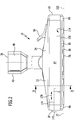
- the contact device 74 also has a first transverse side 84 and a second transverse side 86 (cf. Figure 2 ), which are formed on corresponding transverse elements and, for example, are each rectilinear and spaced parallel to one another.
- the first transverse side 84 and the second transverse side 86 connect the first longitudinal side 80 and the second longitudinal side 82 in the sense that the contact device 74 forms a closed circumferential wall around the suction mouth 70, which defines the suction chamber 78.
- the connection between the first transverse side 84 and the second transverse side 86 is designed such that it is fluid-tight.
- the first transverse side 84 and the second transverse side 86 can each be fixedly connected to the first longitudinal side 80 and the second longitudinal side 82 or can be loosely joined to one another with the requirement of fluid tightness.
- the wall of the contact device 74 which is formed by the long side 80, the second long side 82, the first transverse side 84 and the second transverse side 86, has, for example, a rectangular shape or an approximate rectangular shape on its end face, which lies against the surface 72 to be cleaned .
- the contact device 74 can comprise brush strips and / or lip strips with an elastic lip (and in particular a rubber lip) on their longitudinal sides 80, 82 and on their transverse sides 84, 86.
- the first long side 80 is formed on a brush strip 88 and the second long side 82 is formed on a lip strip 90.
- first transverse side 84 and the second transverse side 86 are each formed on a lip bar.
- the contact device 74 is used when the surface 72 to be cleaned is a hard surface.
- a textile surface cleaning function is provided for cleaning a textile structure and in particular a carpet, in which the contact device 74 does not come into contact with the surface 72 to be cleaned.
- the contact device 74 is arranged on a carrier 92.
- the carrier 92 is movable. It is coupled via a mechanism 94 to a switch 96 which is arranged on the housing cover 22.
- the switch 96 is shown in a position in which the floor nozzle 10 is in a hard surface cleaning function.
- the first long side 80 of the contact device 74 is provided with openings 98 (cf. Figure 2 ).
- An opening 98 fluidically connects an outer space 100 to the suction space 78. Dust particles can pass through the openings 98 from the outer space 100 into the suction space 78 and be suctioned off.
- the openings 98 which are spaced apart from one another, form free spaces with respect to the end face 96, that is to say the openings 98 each protrude up to an envelope line 102 ( Figure 1 ) of the first longitudinal side 80 on the end face 76.
- the opening 98 on the surface 72 to be cleaned is open, in order, as mentioned above, to allow dirt particles to pass from the outer space 100 into the suction space 78 in particular when pushing the floor nozzle 10 in the forward stroke direction 64.
- At least one movable bar 104 for covering the openings 98 is assigned to the contact device 74.
- a movable bar 104 is assigned to the first longitudinal side 80 of the contact device 74 with the openings 98.
- the movable bar 104 is arranged between the first longitudinal side 80 of the contact device 74 and the front wall 14. It is in particular arranged between the floor body 68 and the front wall 14. It is at least partially positioned in the housing interior 28.
- the movable bar 104 has one or more cover elements 106 which can cover the openings 98.
- a cover member 106 is continuously formed in the longitudinal direction of the movable bar 104 to provide a closed surface.
- the cover element 106 can be designed as a brush element or as a lip element with an elastic lip and in particular a rubber lip.
- the movable bar 104 it is also possible for the movable bar 104 to have cover elements only at the locations of the openings 98.
- a first position 108 is provided for the movable bar 104 ( Figures 4 , 5 , 6 ), which are a cover position or closed position for the openings 98.
- the suction chamber 98 is also closed when the contact device 74 is in contact with the openings 98 by contacting the movable bar 104 via an end face 110 on the surface 72 to be cleaned.
- the movable bar 104 has a second position 114 ( Figures 2 , 3rd , 6 ), which is a release position. In this release position 114, the movable bar 104 does not cover the openings 98, so that dirt particles can get from the outer space 100 through the openings 98 into the suction space 78.
- the movable bar 104 is movable between the first position 108 and the second position 114 or between the second position 114 and the first position 108.
- a movement mechanism 116 is provided for this.
- This movement mechanism 116 is in turn designed such that it is coupled with a stroke of the floor nozzle 10 and in particular with a stroke direction of the floor nozzle 10.
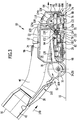
- Movement mechanism 116 includes a first arm 118 ( Figures 3 , 5 , 6 ) which is arranged on the base body 68 so as to be pivotable about a pivot axis 120 via a pivot joint 122 and is therefore pivotably arranged on and relative to the housing 12.
- the first arm 118 is designed as an angle element. This angular element of the first arm 118 comprises a first region 124a, which is articulated to the floor body 68 via the swivel joint 122, and a second region 124b, which is oriented transversely and in particular perpendicularly to the first region 124a.
- a pivoting movement of the first arm 118 causes the movable bar 104 to move between the first position 108 and the second position 114 or between the second position 114 and the first position 108.
- the movement mechanism 116 also has a second arm 128 which is articulated on the first arm 118.
- the second arm 128 is coupled to a device 160 which is movable relative to the floor body 68.
- the position of the device 160 relative to the base body 68 determines the position of the second arm 128 and thus the position of the first arm 118 and thus in turn the position of the movable bar 104.
- This coupling of the second arm 128 to the device 160 effectively provides the "control signal" ready in which position (108 or 114) the movable bar 104 is brought.
- the movable device 160 is movable relative to the floor body 68.
- the device 160 has a first position 162 in a rearward stroke direction 66 of the floor nozzle 10 ( Figures 5 and 6 ). This first position 162 of the device 160 corresponds to the first position 108 of the movable bar 104.
- the device 160 also has a second position 164 in a forward stroke direction 64 of the floor nozzle 10 ( Figures 3 and 6 ).
- the second position 164 of the device 160 relative to the floor body 68 corresponds to the second position 114 of the movable bar 104.
- the first position 162 of the device 160 and the second position 164 of the device 160 differ in a distance 166 of the tilt axis 58 of the tilt joint 52 from the base body 68 and from the housing 12 (in Figure 6 the distance 166 is the distance between the axis 34 and the rear wall 16).
- the device 160 which is movable relative to the base body 68, comprises the roller device 32 and the connection body 40.
- the hose 46 is fixed both to the connection body 40 and to the base body 68. Its flexible design allows the device 160 to move relative to the floor body 68.
- the second arm 128 is fixed, for example, to the cylindrical region 54 and projects from there into the housing interior 28.
- the housing 12 which is fixedly connected to the base body 68, is relative to the cylindrical region 54, which is connected to the device 160, movable. This provides a relative mobility between the second arm 128 and the housing interior 28.
- the mobility includes a linear component of displacement.
- the second arm 128 is articulated to the first region 124a of the first arm 118 and is articulated in such a way that a relative movement of the second arm 128 to the housing interior 28 into a movement of the movable bar 104 from the first position 108 to the second position 114 or can be effected from the second position 114 into the first position 108 or the corresponding position 114 or 108 is then held.
- the second arm 128 connects the device 160 to the housing 12, the connection being movable.
- a guide device 130 is provided, which is designed such that a linear displacement of the second arm 128 or a linear displacement component of the second arm 128 relative to the housing interior 28 into a pivoting movement of the first arm 118 is feasible.
- the guide device 130 is designed in particular as a recess-pin guide 132 (link guide). For this purpose, it comprises a recess 134 for example on the first arm 118. This recess 134 is designed as a longitudinal slot.
- a pin 136 dips into this recess 134. If the recess 134 is formed on the first arm 118, this is arranged on the second arm 128.
- the pin 136 is displaceable in the recess 134, a displacement causing a pivoting movement about the pivot axis 120 of the first arm 118.
- the recess-pin guide 132 is designed such that when the pin 136 rests on a boundary wall 138 of the recess 134 ( Figure 3 ) the release position (second position 114) is reached. Further pivoting of the first arm 118 away from the floor body 68 is then blocked.
- the movement mechanism 116 functions as follows (compare the Figures 3 , 5 and 6 ):
- a force 140 is exerted, which is oriented obliquely to the surface 72 to be cleaned, on which the floor nozzle 10 is moved (with a corresponding oblique orientation of the pipe axis of the pipe section 44 to the surface 72).
- the device 160 is moved towards the housing 12 until an end position (second position 164) is reached.
- This relative displacement is caused by the friction between the floor body 68 and the surface 72 to be cleaned, the floor body 68 sucking itself up in a suction operation.
- a force is transmitted to the first arm 118 via the second arm 128. If the movable bar 104 is not in the second position 114 (release position), it is brought into the second position 114. If this is already in the second position 114, this second position 114 is held.
- the surface 72 to be cleaned can then be sucked with a forward stroke movement, whereby dirt particles can get into the suction chamber 78 via the openings 98.
- a force is exerted with a force vector 142 ( Figure 5 ), which is oriented approximately in the opposite direction to the force 140 when moving in the forward stroke direction 64.
- the device 160 with the second arm 128 moves away from the housing 12 until an end position (first position 162) is reached. This relative displacement is caused by the friction between the floor body 68 and the surface 72 to be cleaned, the floor body 68 sucking itself up in a suction operation.
- the force is transmitted to the first arm 118 via the second arm 128. If the first arm 118 is not in the first position 108 (covering position), a pivoting movement of the first arm 118 onto the base body 68 is initiated, which then brings the movable bar 104 into the first position 108 (covering position).
- the movable bar 104 is already in the first position 108, then it is held in this first position 108.
- the openings 98 are then covered by the movable bar 104 with its cover element or its cover elements 106. As a result, an at least approximately fluid-tight wall is formed around the suction space 78. In this way, cracks 112 or the like can be effectively suctioned off on the surface 72 to be cleaned.
- an operator of the corresponding vacuum cleaner with the floor nozzle 10 can use the movable bar 104 and the movement mechanism 116 to set whether the openings 98 are to be covered (first position 108 of the movable one) Bar 104) or should be released (second position 114 of the movable bar 104).
- the first position 162 (in broken lines) and the second position 164 of the device 160 are shown superimposed. Furthermore, the resulting positions 108 (in broken lines) or 114 of the movable bar 104 are shown, the first position 108 of the movable bar 104 corresponding to the first position 162 of the device 160, and the second position 114 of the movable bar 104 with corresponds to the second position 164 of the device 160.
- the floor nozzle can basically be of the same design as the floor nozzle, which is not in the previously published international application PCT / EP2015 / 054764 from March 6, 2015 by the same applicant, wherein the floor nozzle 10 then the additional functionality of the movable bar 104 compared to that in the PCT / EP2015 / 054764 described floor nozzle.
- the floor nozzle 10 is placed on the surface 72 to be cleaned.
- the contact device 74 is brought into its effective position, so that its end face 76 touches the surface 72 to be cleaned.
- the movable bar 104 is in the second position 114 ( Release position) or in the first position 108 (cover position).
- dirt particles can enter the suction space 78 via the openings 98 and be sucked off.
- An operator can thereby set the position (108 or 114) of the movable bar 104 on the surface 72 to be cleaned via the stroke direction of the floor nozzle 10.
- the automatic adjustment takes place in accordance with the "natural application", so that an operator does not have to think about the position adjustment, but rather, as mentioned, automatically adjusts the correct position.
- Movement mechanism 116 has been described in connection with first arm 118 and second arm 128. It can be provided that a plurality of elements corresponding to the first arm 118 are provided, which are spaced apart. It is also possible that a plurality of elements corresponding to the second arm 128 are provided spaced apart from one another. The at least one movable bar 104 is then held by these first arms 118. Accordingly, the second arm or arms 128 then couple to the first arms 118.
- a locking device 170 is provided (compare Figure 2 ), which serves to fix the first position 108 and / or the second position 114, so that the bar, which is movable per se, does not move even when the stroke direction changes.
- an operator can determine, in particular in a controlled manner, the position in which the strip 104 is held.
- the locking device 170 designed so that the second position 114 can be fixed. This fixes the bar 104 "in a non-operative position".
- the first position 108 is fixed.
- the movable bar 104 is always in an operative position, regardless of whether a forward stroke or a reverse stroke of the floor nozzle 10 takes place.
- an operator can set both the first position 108 and the second position 114 as alternatives.
- the locking device 170 allows the automatic setting of the position of the movable bar 104 in its first position 108 or in its second position 114 to be “switched off” as a function of the stroke direction of the floor nozzle 10. Movement mechanism 116 is blocked.
- the locking device 170 comprises a switch 172 which is accessible to an operator.
- This switch 172 is arranged, for example, on the upper side 24 of the housing 12 or on a lateral side, for example the first side wall 18.
- the switch 172 is coupled to an element 174 which acts on the movement mechanism 116 and can correspondingly block the mobility of the quiet 104.
- element 174 is a pin element which is mounted in housing 12 in such a way that it can act on recess 134 of recess-pin guide 132.
- the element 174 dips into the recess 134, so that the pin 136 can no longer be displaced in the recess 134.
- an operator can use the switch 172 to set whether the pin element 174 is immersed in the recess 134 and has a locking effect (and thus defines the second position 114), or whether the pin element 174 is removed from the recess 134 is and thus an automatic adjustment of the position of the bar 104 is possible depending on the stroke direction.
- the pin element 174 is arranged and dimensioned such that it has the first position 108 ( Figure 5 ) locks.
- the pin element 174 can also dip into the recess 134, the dipability being controlled via the switch 172. Pivotal movement of the first arm 118 is blocked by the pin element 174 blocking a relative movement of the pin 136 to the recess 134.
- an immersion direction 176 for the pin element 174 is indicated.
- the element 174 is correspondingly displaceably mounted in the immersion direction 176 in order to enable it to be immersed in the recess 134 or to be exchangeable.
- the mounting of the element 174 is such that the second position 114 can be fixed or the first position 108 can be fixed.
- Several and in particular two corresponding elements 174 can also be provided, one element serving to fix the second position 114 and one element to fix the first position 108.
- a single element corresponding to element 174 can be provided, which also has a mobility transverse to immersion direction 176 in order to determine the first position 108 or the second position depending on the position of switch 172, which is then in particular a rotary switch To enable position 114. (In a further switch position, element 174 is then positioned such that it does not act on recess-pin guide 132.)
Landscapes
- Engineering & Computer Science (AREA)
- Mechanical Engineering (AREA)
- Nozzles For Electric Vacuum Cleaners (AREA)
Claims (14)
- Buse de sol pour un aspirateur, comprenant un corps plancher (68), au moins une bouche d'aspiration (70), laquelle est disposée sur le corps plancher (68) et est ou peut être en liaison fluidique avec un groupe d'aspiration (31), et un dispositif d'application (74), lequel peut être appliqué sur une surface (72) à nettoyer et lequel entoure l'au moins une bouche d'aspiration (70), dans laquelle, lorsque le dispositif d'application (74) est appliqué sur la surface (72) à nettoyer, un espace d'aspiration (78), dans lequel débouche la bouche d'aspiration (70), est formé entre la surface (72) à nettoyer et le dispositif d'application (74), et dans laquelle le dispositif d'application (74) présente sur au moins une face (80) des ouvertures (98) dans l'espace d'aspiration (78), et dans laquelle au moins une barre mobile (104), laquelle présente au moins deux positions (108, 114), est associée à l'au moins une face (80) avec les ouvertures (98), dans laquelle une première position (108) est une position de fermeture, dans laquelle les ouvertures (98) sont recouvertes, et une deuxième position (114) est une position de libération, dans laquelle les ouvertures (98) sont libérées, caractérisée en ce qu'un mécanisme de déplacement (116) pour l'au moins une barre mobile (104) est présent, lequel couple la position de l'au moins une barre mobile (104) à une élévation de la buse de sol sur la surface (72) à nettoyer et que le mécanisme de déplacement (116) présente un premier bras (118), lequel est monté de manière pivotante par rapport au corps plancher (68) et sur lequel l'au moins une barre mobile (104) est disposée, dans laquelle un mouvement pivotant du premier bras (118) provoque un mouvement de l'au moins une barre mobile (104).
- Buse de sol selon la revendication 1, caractérisée en ce que le mécanisme de déplacement (116) est réalisé de sorte qu'il couple la position de l'au moins une barre mobile (104) à une direction d'élévation (64, 66) de la buse de sol sur la surface (72) à nettoyer.
- Buse de sol selon la revendication 1 ou 2, caractérisée en ce que le dispositif d'application (74) présente un premier grand côté (80), un deuxième grand côté (82) espacé du premier grand côté (80), un premier côté transversal (84), lequel est disposé entre le premier grand côté (80) et le deuxième grand côté (82), et un deuxième côté transversal (86), espacé du premier côté transversal (84), lequel est disposé entre le premier grand côté (80) et le deuxième grand côté (82), dans laquelle les ouvertures (98) sont disposées sur le premier grand côté (80) et/ou le deuxième grand côté (82) et dans laquelle l'au moins une barre mobile (104) est associée au premier grand côté (80) et/ou au deuxième grand côté (82).
- Buse de sol selon la revendication 3, caractérisée en ce que, lors d'une élévation avant de la buse de sol, celle-ci est déplacée dans une direction (64) parallèle à une direction allant du deuxième grand côté (82) au premier grand côté (80), et, lors d'une élévation arrière de la buse de sol, celle-ci est déplacée dans une direction (66) parallèle à une direction allant du premier grand côté (80) au deuxième grand côté (82), dans laquelle l'au moins une barre mobile (104) est associée au premier grand côté (80) et le mécanisme de déplacement (116) est réalisé de sorte que, lors de l'élévation avant, l'au moins une barre mobile (104) est dans la position de libération (114) et, lors de l'élévation arrière, l'au moins une barre mobile (104) est dans la position de fermeture (108).
- Buse de sol selon la revendication 3 ou 4, caractérisée en ce que l'au moins une barre mobile (104) est positionnée entre le premier grand côté (80) et une paroi avant (14), voisine du premier grand côté (80), de la buse de sol et/ou entre le deuxième grand côté (82) et une paroi arrière (16), voisine du deuxième grand côté (82), de la buse de sol.
- Buse de sol selon l'une quelconque des revendications précédentes, caractérisée en ce que le dispositif d'application (74) présente une ou plusieurs barres à brosse (88) et/ou une ou plusieurs barres à lèvre (90) .
- Buse de sol selon l'une quelconque des revendications précédentes, caractérisée en ce que l'au moins une barre mobile (104) est réalisée sous la forme d'une barre à lèvre ou barre à brosse.
- Buse de sol selon l'une quelconque des revendications précédentes, caractérisée en ce qu'un deuxième bras (128) est articulé sur le premier bras (118), dans laquelle le deuxième bras (128) est accouplé à un dispositif (160) de la buse de sol, lequel est mobile par rapport au corps plancher (68), dans laquelle une position du dispositif (160) par rapport au corps plancher (68) dépend de l'élévation de la buse de sol sur la surface (72) à nettoyer.
- Buse de sol selon la revendication 8, caractérisée en ce que le dispositif (160) mobile par rapport au corps plancher (68) comprend un dispositif à rouleau (32), et en particulier que le deuxième bras (128) est accouplé au dispositif (160) mobile dans la zone du dispositif à rouleau (32).
- Buse de sol selon la revendication 8 ou 9, caractérisée en ce que le premier bras (118) et le deuxième bras (128) sont articulés l'un sur l'autre par l'intermédiaire d'un dispositif de guidage (130), lequel permet un coulissement relatif entre le premier bras (118) et le deuxième bras (128), dans laquelle le dispositif de guidage (130) comprend en particulier un guidage à évidement et tige (132).
- Buse de sol selon la revendication 10, caractérisée en ce que le dispositif de guidage (130) définit la position de libération (114) et en particulier une application d'une tige (136) du guidage à évidement et tige (132) sur une délimitation (138) d'un évidement (134) du guidage à évidement et tige (132) définit la position de libération (114).
- Buse de sol selon l'une quelconque des revendications précédentes, caractérisée par au moins une articulation à basculement (52), laquelle présente un axe de basculement (58), qui est parallèle à un axe de pivotement (120) du premier bras (118).
- Buse de sol selon l'une quelconque des revendications précédentes, caractérisée en ce que, dans la position de fermeture (108) de l'au moins une barre mobile (104), une face frontale (110), tournée vers la surface (72) à nettoyer, de l'au moins une barre mobile (104) se situe au moins approximativement dans un plan avec une face frontale (76) correspondante du dispositif d'application (74).
- Buse de sol selon l'une quelconque des revendications précédentes, caractérisée par un dispositif de blocage (170), par lequel la première position (108) et/ou la deuxième position (114) peuvent être bloquées, et en particulier que le dispositif de blocage (170) comprend un commutateur (172), et en particulier que le dispositif de blocage (170) comprend au moins un élément mobile (174), lequel agit sur un guidage à évidement et tige (132), et dans laquelle le premier bras (118) et le deuxième bras (128) sont articulés l'un sur l'autre par l'intermédiaire du guidage à évidement et tige (132), lequel permet un coulissement relatif entre le premier bras (118) et le deuxième bras (128) .
Applications Claiming Priority (1)
| Application Number | Priority Date | Filing Date | Title |
|---|---|---|---|
| PCT/EP2015/070571 WO2017041837A1 (fr) | 2015-09-09 | 2015-09-09 | Buse de sol |
Publications (2)
| Publication Number | Publication Date |
|---|---|
| EP3346894A1 EP3346894A1 (fr) | 2018-07-18 |
| EP3346894B1 true EP3346894B1 (fr) | 2020-04-29 |
Family
ID=54065373
Family Applications (1)
| Application Number | Title | Priority Date | Filing Date |
|---|---|---|---|
| EP15760195.6A Active EP3346894B1 (fr) | 2015-09-09 | 2015-09-09 | Buse de sol |
Country Status (3)
| Country | Link |
|---|---|
| EP (1) | EP3346894B1 (fr) |
| CN (1) | CN108024675B (fr) |
| WO (1) | WO2017041837A1 (fr) |
Families Citing this family (1)
| Publication number | Priority date | Publication date | Assignee | Title |
|---|---|---|---|---|
| DE102021116686B3 (de) * | 2021-06-29 | 2022-08-25 | Hako Gmbh | Bodenreinigungsmaschine |
Family Cites Families (6)
| Publication number | Priority date | Publication date | Assignee | Title |
|---|---|---|---|---|
| JPH10179460A (ja) * | 1996-12-20 | 1998-07-07 | Fujitsu General Ltd | 電気掃除機の床用吸込具 |
| ES2260147T3 (es) * | 2000-12-13 | 2006-11-01 | VORWERK & CO. INTERHOLDING GMBH | Tobera para un aspirador de polvo. |
| DE102004005144A1 (de) * | 2004-02-03 | 2005-08-18 | Vorwerk & Co. Interholding Gmbh | Bodendüse für einen Staubsauger |
| GB2469459B (en) * | 2009-04-14 | 2013-05-22 | Dyson Technology Ltd | A cleaner head |
| DE102013109469A1 (de) * | 2013-08-30 | 2015-03-05 | Vorwerk & Co. Interholding Gmbh | Bodendüse für einen Staubsauger |
| DE102013223863A1 (de) * | 2013-11-21 | 2015-05-21 | BSH Hausgeräte GmbH | Saugdüse für einen Staubsauger |
-
2015
- 2015-09-09 WO PCT/EP2015/070571 patent/WO2017041837A1/fr not_active Ceased
- 2015-09-09 EP EP15760195.6A patent/EP3346894B1/fr active Active
- 2015-09-09 CN CN201580083021.7A patent/CN108024675B/zh active Active
Non-Patent Citations (1)
| Title |
|---|
| None * |
Also Published As
| Publication number | Publication date |
|---|---|
| WO2017041837A1 (fr) | 2017-03-16 |
| CN108024675A (zh) | 2018-05-11 |
| EP3346894A1 (fr) | 2018-07-18 |
| CN108024675B (zh) | 2021-04-20 |
Similar Documents
| Publication | Publication Date | Title |
|---|---|---|
| EP2098150B1 (fr) | Bas d'aspiration pour un aspirateur de sol | |
| DE60013774T2 (de) | Staubsaugermundstück | |
| EP2989953B1 (fr) | Utilisation d'une buse d'aspiration pouvant etre raccordee a un aspirateur pour aspirer une surface textile, une surface de sol dur dalle et une surface de sol dur lisse sans joint | |
| WO2001054555A1 (fr) | Tete de nettoyage pour un appareil de nettoyage de sols | |
| WO1996032876A1 (fr) | Embout d'aspirateur pour le nettoyage humide de surfaces | |
| EP2449935B1 (fr) | Buse d'aspiration et aspirateur de sol | |
| DE102008034458B4 (de) | Handgeführte Saugdüse zum Anschluss an einen Staubsauger und Saugdüse trennbar mit einem Düsenvorsatz | |
| EP3547889B1 (fr) | Appareil de nettoyage et procédé de fonctionnement d'un appareil de nettoyage | |
| EP2449934A2 (fr) | Agencement de buses d'aspiration pour un aspirateur de sol | |
| DE102017127131A1 (de) | Regenerierbarer Staubsauger | |
| EP0235614B1 (fr) | Suceur d'aspirateur avec un manchon de raccord basculant et un corps de suceur | |
| EP3025626A1 (fr) | Buse de sol pour un appareil d'entretien du sol et procede de fabrication d'une buse de sol pour un appareil d'entretien du sol | |
| EP2587977B1 (fr) | Buse pour aspirateur | |
| EP1138246A2 (fr) | Dispositif pour l'essorage de serpillières absorbant les liquides | |
| DE69906683T2 (de) | Staubsaugermundstück | |
| DE102004061971B4 (de) | Bodendüse für Staubsauger | |
| EP3346894B1 (fr) | Buse de sol | |
| DE102019120933B4 (de) | Saugdüse für einen Staubsauger und Staubsauger mit einer Saugdüse | |
| EP3500145B1 (fr) | Suceur pour un aspirateur, procédé d'aspiration de surfaces textiles et aspirateur | |
| DE10138752C1 (de) | Vorrichtung zur Halterung eines Staubbeutels | |
| DE3143355A1 (de) | "saugduese zum absaugen von fluessigkeiten" | |
| DE102016115576A1 (de) | Saugdüse für einen Staubsauger | |
| EP3048943B1 (fr) | Suceur d'aspirateur pour appareil de nettoyage et appareil de nettoyage | |
| EP0956806B1 (fr) | Dispositif d'aspiration pour aspirer des saletés ou des matières contenant des saletés | |
| WO2020165049A1 (fr) | Buse de sol pour un appareil de nettoyage avec fonction d'aspiration, appareil de nettoyage et procédé pour l'aspiration d'une zone du sol |
Legal Events
| Date | Code | Title | Description |
|---|---|---|---|
| STAA | Information on the status of an ep patent application or granted ep patent |
Free format text: STATUS: THE INTERNATIONAL PUBLICATION HAS BEEN MADE |
|
| PUAI | Public reference made under article 153(3) epc to a published international application that has entered the european phase |
Free format text: ORIGINAL CODE: 0009012 |
|
| STAA | Information on the status of an ep patent application or granted ep patent |
Free format text: STATUS: REQUEST FOR EXAMINATION WAS MADE |
|
| 17P | Request for examination filed |
Effective date: 20180301 |
|
| AK | Designated contracting states |
Kind code of ref document: A1 Designated state(s): AL AT BE BG CH CY CZ DE DK EE ES FI FR GB GR HR HU IE IS IT LI LT LU LV MC MK MT NL NO PL PT RO RS SE SI SK SM TR |
|
| AX | Request for extension of the european patent |
Extension state: BA ME |
|
| RIN1 | Information on inventor provided before grant (corrected) |
Inventor name: HOERSCH, CHRISTOPH Inventor name: BAUMGART, JULIA Inventor name: KNEE, ROGER Inventor name: SIEGEL, STEPHAN |
|
| RAP1 | Party data changed (applicant data changed or rights of an application transferred) |
Owner name: ALFRED KAERCHER SE & CO. KG |
|
| DAV | Request for validation of the european patent (deleted) | ||
| DAX | Request for extension of the european patent (deleted) | ||
| STAA | Information on the status of an ep patent application or granted ep patent |
Free format text: STATUS: EXAMINATION IS IN PROGRESS |
|
| 17Q | First examination report despatched |
Effective date: 20190404 |
|
| GRAP | Despatch of communication of intention to grant a patent |
Free format text: ORIGINAL CODE: EPIDOSNIGR1 |
|
| STAA | Information on the status of an ep patent application or granted ep patent |
Free format text: STATUS: GRANT OF PATENT IS INTENDED |
|
| INTG | Intention to grant announced |
Effective date: 20191128 |
|
| GRAS | Grant fee paid |
Free format text: ORIGINAL CODE: EPIDOSNIGR3 |
|
| GRAA | (expected) grant |
Free format text: ORIGINAL CODE: 0009210 |
|
| STAA | Information on the status of an ep patent application or granted ep patent |
Free format text: STATUS: THE PATENT HAS BEEN GRANTED |
|
| AK | Designated contracting states |
Kind code of ref document: B1 Designated state(s): AL AT BE BG CH CY CZ DE DK EE ES FI FR GB GR HR HU IE IS IT LI LT LU LV MC MK MT NL NO PL PT RO RS SE SI SK SM TR |
|
| REG | Reference to a national code |
Ref country code: GB Ref legal event code: FG4D Free format text: NOT ENGLISH |
|
| REG | Reference to a national code |
Ref country code: CH Ref legal event code: EP |
|
| REG | Reference to a national code |
Ref country code: AT Ref legal event code: REF Ref document number: 1262064 Country of ref document: AT Kind code of ref document: T Effective date: 20200515 |
|
| REG | Reference to a national code |
Ref country code: DE Ref legal event code: R096 Ref document number: 502015012446 Country of ref document: DE |
|
| REG | Reference to a national code |
Ref country code: IE Ref legal event code: FG4D Free format text: LANGUAGE OF EP DOCUMENT: GERMAN |
|
| REG | Reference to a national code |
Ref country code: NL Ref legal event code: MP Effective date: 20200429 |
|
| REG | Reference to a national code |
Ref country code: LT Ref legal event code: MG4D |
|
| PG25 | Lapsed in a contracting state [announced via postgrant information from national office to epo] |
Ref country code: GR Free format text: LAPSE BECAUSE OF FAILURE TO SUBMIT A TRANSLATION OF THE DESCRIPTION OR TO PAY THE FEE WITHIN THE PRESCRIBED TIME-LIMIT Effective date: 20200730 Ref country code: PT Free format text: LAPSE BECAUSE OF FAILURE TO SUBMIT A TRANSLATION OF THE DESCRIPTION OR TO PAY THE FEE WITHIN THE PRESCRIBED TIME-LIMIT Effective date: 20200831 Ref country code: IS Free format text: LAPSE BECAUSE OF FAILURE TO SUBMIT A TRANSLATION OF THE DESCRIPTION OR TO PAY THE FEE WITHIN THE PRESCRIBED TIME-LIMIT Effective date: 20200829 Ref country code: SE Free format text: LAPSE BECAUSE OF FAILURE TO SUBMIT A TRANSLATION OF THE DESCRIPTION OR TO PAY THE FEE WITHIN THE PRESCRIBED TIME-LIMIT Effective date: 20200429 Ref country code: FI Free format text: LAPSE BECAUSE OF FAILURE TO SUBMIT A TRANSLATION OF THE DESCRIPTION OR TO PAY THE FEE WITHIN THE PRESCRIBED TIME-LIMIT Effective date: 20200429 Ref country code: NO Free format text: LAPSE BECAUSE OF FAILURE TO SUBMIT A TRANSLATION OF THE DESCRIPTION OR TO PAY THE FEE WITHIN THE PRESCRIBED TIME-LIMIT Effective date: 20200729 Ref country code: LT Free format text: LAPSE BECAUSE OF FAILURE TO SUBMIT A TRANSLATION OF THE DESCRIPTION OR TO PAY THE FEE WITHIN THE PRESCRIBED TIME-LIMIT Effective date: 20200429 |
|
| PG25 | Lapsed in a contracting state [announced via postgrant information from national office to epo] |
Ref country code: RS Free format text: LAPSE BECAUSE OF FAILURE TO SUBMIT A TRANSLATION OF THE DESCRIPTION OR TO PAY THE FEE WITHIN THE PRESCRIBED TIME-LIMIT Effective date: 20200429 Ref country code: LV Free format text: LAPSE BECAUSE OF FAILURE TO SUBMIT A TRANSLATION OF THE DESCRIPTION OR TO PAY THE FEE WITHIN THE PRESCRIBED TIME-LIMIT Effective date: 20200429 Ref country code: BG Free format text: LAPSE BECAUSE OF FAILURE TO SUBMIT A TRANSLATION OF THE DESCRIPTION OR TO PAY THE FEE WITHIN THE PRESCRIBED TIME-LIMIT Effective date: 20200729 Ref country code: HR Free format text: LAPSE BECAUSE OF FAILURE TO SUBMIT A TRANSLATION OF THE DESCRIPTION OR TO PAY THE FEE WITHIN THE PRESCRIBED TIME-LIMIT Effective date: 20200429 |
|
| PG25 | Lapsed in a contracting state [announced via postgrant information from national office to epo] |
Ref country code: NL Free format text: LAPSE BECAUSE OF FAILURE TO SUBMIT A TRANSLATION OF THE DESCRIPTION OR TO PAY THE FEE WITHIN THE PRESCRIBED TIME-LIMIT Effective date: 20200429 Ref country code: AL Free format text: LAPSE BECAUSE OF FAILURE TO SUBMIT A TRANSLATION OF THE DESCRIPTION OR TO PAY THE FEE WITHIN THE PRESCRIBED TIME-LIMIT Effective date: 20200429 |
|
| PG25 | Lapsed in a contracting state [announced via postgrant information from national office to epo] |
Ref country code: IT Free format text: LAPSE BECAUSE OF FAILURE TO SUBMIT A TRANSLATION OF THE DESCRIPTION OR TO PAY THE FEE WITHIN THE PRESCRIBED TIME-LIMIT Effective date: 20200429 Ref country code: RO Free format text: LAPSE BECAUSE OF FAILURE TO SUBMIT A TRANSLATION OF THE DESCRIPTION OR TO PAY THE FEE WITHIN THE PRESCRIBED TIME-LIMIT Effective date: 20200429 Ref country code: EE Free format text: LAPSE BECAUSE OF FAILURE TO SUBMIT A TRANSLATION OF THE DESCRIPTION OR TO PAY THE FEE WITHIN THE PRESCRIBED TIME-LIMIT Effective date: 20200429 Ref country code: SM Free format text: LAPSE BECAUSE OF FAILURE TO SUBMIT A TRANSLATION OF THE DESCRIPTION OR TO PAY THE FEE WITHIN THE PRESCRIBED TIME-LIMIT Effective date: 20200429 Ref country code: DK Free format text: LAPSE BECAUSE OF FAILURE TO SUBMIT A TRANSLATION OF THE DESCRIPTION OR TO PAY THE FEE WITHIN THE PRESCRIBED TIME-LIMIT Effective date: 20200429 Ref country code: CZ Free format text: LAPSE BECAUSE OF FAILURE TO SUBMIT A TRANSLATION OF THE DESCRIPTION OR TO PAY THE FEE WITHIN THE PRESCRIBED TIME-LIMIT Effective date: 20200429 Ref country code: ES Free format text: LAPSE BECAUSE OF FAILURE TO SUBMIT A TRANSLATION OF THE DESCRIPTION OR TO PAY THE FEE WITHIN THE PRESCRIBED TIME-LIMIT Effective date: 20200429 |
|
| REG | Reference to a national code |
Ref country code: DE Ref legal event code: R097 Ref document number: 502015012446 Country of ref document: DE |
|
| PG25 | Lapsed in a contracting state [announced via postgrant information from national office to epo] |
Ref country code: SK Free format text: LAPSE BECAUSE OF FAILURE TO SUBMIT A TRANSLATION OF THE DESCRIPTION OR TO PAY THE FEE WITHIN THE PRESCRIBED TIME-LIMIT Effective date: 20200429 Ref country code: PL Free format text: LAPSE BECAUSE OF FAILURE TO SUBMIT A TRANSLATION OF THE DESCRIPTION OR TO PAY THE FEE WITHIN THE PRESCRIBED TIME-LIMIT Effective date: 20200429 |
|
| PLBE | No opposition filed within time limit |
Free format text: ORIGINAL CODE: 0009261 |
|
| STAA | Information on the status of an ep patent application or granted ep patent |
Free format text: STATUS: NO OPPOSITION FILED WITHIN TIME LIMIT |
|
| 26N | No opposition filed |
Effective date: 20210201 |
|
| REG | Reference to a national code |
Ref country code: CH Ref legal event code: PL |
|
| GBPC | Gb: european patent ceased through non-payment of renewal fee |
Effective date: 20200909 |
|
| PG25 | Lapsed in a contracting state [announced via postgrant information from national office to epo] |
Ref country code: SI Free format text: LAPSE BECAUSE OF FAILURE TO SUBMIT A TRANSLATION OF THE DESCRIPTION OR TO PAY THE FEE WITHIN THE PRESCRIBED TIME-LIMIT Effective date: 20200429 |
|
| REG | Reference to a national code |
Ref country code: BE Ref legal event code: MM Effective date: 20200930 |
|
| PG25 | Lapsed in a contracting state [announced via postgrant information from national office to epo] |
Ref country code: LU Free format text: LAPSE BECAUSE OF NON-PAYMENT OF DUE FEES Effective date: 20200909 |
|
| PG25 | Lapsed in a contracting state [announced via postgrant information from national office to epo] |
Ref country code: FR Free format text: LAPSE BECAUSE OF NON-PAYMENT OF DUE FEES Effective date: 20200930 |
|
| PG25 | Lapsed in a contracting state [announced via postgrant information from national office to epo] |
Ref country code: IE Free format text: LAPSE BECAUSE OF NON-PAYMENT OF DUE FEES Effective date: 20200909 Ref country code: GB Free format text: LAPSE BECAUSE OF NON-PAYMENT OF DUE FEES Effective date: 20200909 Ref country code: LI Free format text: LAPSE BECAUSE OF NON-PAYMENT OF DUE FEES Effective date: 20200930 Ref country code: CH Free format text: LAPSE BECAUSE OF NON-PAYMENT OF DUE FEES Effective date: 20200930 Ref country code: BE Free format text: LAPSE BECAUSE OF NON-PAYMENT OF DUE FEES Effective date: 20200930 |
|
| REG | Reference to a national code |
Ref country code: AT Ref legal event code: MM01 Ref document number: 1262064 Country of ref document: AT Kind code of ref document: T Effective date: 20200909 |
|
| PG25 | Lapsed in a contracting state [announced via postgrant information from national office to epo] |
Ref country code: AT Free format text: LAPSE BECAUSE OF NON-PAYMENT OF DUE FEES Effective date: 20200909 |
|
| PG25 | Lapsed in a contracting state [announced via postgrant information from national office to epo] |
Ref country code: TR Free format text: LAPSE BECAUSE OF FAILURE TO SUBMIT A TRANSLATION OF THE DESCRIPTION OR TO PAY THE FEE WITHIN THE PRESCRIBED TIME-LIMIT Effective date: 20200429 Ref country code: MT Free format text: LAPSE BECAUSE OF FAILURE TO SUBMIT A TRANSLATION OF THE DESCRIPTION OR TO PAY THE FEE WITHIN THE PRESCRIBED TIME-LIMIT Effective date: 20200429 Ref country code: CY Free format text: LAPSE BECAUSE OF FAILURE TO SUBMIT A TRANSLATION OF THE DESCRIPTION OR TO PAY THE FEE WITHIN THE PRESCRIBED TIME-LIMIT Effective date: 20200429 |
|
| PG25 | Lapsed in a contracting state [announced via postgrant information from national office to epo] |
Ref country code: MK Free format text: LAPSE BECAUSE OF FAILURE TO SUBMIT A TRANSLATION OF THE DESCRIPTION OR TO PAY THE FEE WITHIN THE PRESCRIBED TIME-LIMIT Effective date: 20200429 Ref country code: MC Free format text: LAPSE BECAUSE OF FAILURE TO SUBMIT A TRANSLATION OF THE DESCRIPTION OR TO PAY THE FEE WITHIN THE PRESCRIBED TIME-LIMIT Effective date: 20200429 |
|
| P01 | Opt-out of the competence of the unified patent court (upc) registered |
Effective date: 20230523 |
|
| PGFP | Annual fee paid to national office [announced via postgrant information from national office to epo] |
Ref country code: DE Payment date: 20250919 Year of fee payment: 11 |