EP3346943B1 - Precede et system pour un segmentation hybride a mailles - Google Patents
Precede et system pour un segmentation hybride a mailles Download PDFInfo
- Publication number
- EP3346943B1 EP3346943B1 EP16766722.9A EP16766722A EP3346943B1 EP 3346943 B1 EP3346943 B1 EP 3346943B1 EP 16766722 A EP16766722 A EP 16766722A EP 3346943 B1 EP3346943 B1 EP 3346943B1
- Authority
- EP
- European Patent Office
- Prior art keywords
- segmentation
- tooth
- results
- automated
- patient
- Prior art date
- Legal status (The legal status is an assumption and is not a legal conclusion. Google has not performed a legal analysis and makes no representation as to the accuracy of the status listed.)
- Active
Links
Images




Classifications
-
- G—PHYSICS
- G06—COMPUTING OR CALCULATING; COUNTING
- G06T—IMAGE DATA PROCESSING OR GENERATION, IN GENERAL
- G06T7/00—Image analysis
- G06T7/0002—Inspection of images, e.g. flaw detection
- G06T7/0012—Biomedical image inspection
-
- A—HUMAN NECESSITIES
- A61—MEDICAL OR VETERINARY SCIENCE; HYGIENE
- A61B—DIAGNOSIS; SURGERY; IDENTIFICATION
- A61B5/00—Measuring for diagnostic purposes; Identification of persons
- A61B5/0059—Measuring for diagnostic purposes; Identification of persons using light, e.g. diagnosis by transillumination, diascopy, fluorescence
- A61B5/0082—Measuring for diagnostic purposes; Identification of persons using light, e.g. diagnosis by transillumination, diascopy, fluorescence adapted for particular medical purposes
- A61B5/0084—Measuring for diagnostic purposes; Identification of persons using light, e.g. diagnosis by transillumination, diascopy, fluorescence adapted for particular medical purposes for introduction into the body, e.g. by catheters
-
- A—HUMAN NECESSITIES
- A61—MEDICAL OR VETERINARY SCIENCE; HYGIENE
- A61B—DIAGNOSIS; SURGERY; IDENTIFICATION
- A61B5/00—Measuring for diagnostic purposes; Identification of persons
- A61B5/0059—Measuring for diagnostic purposes; Identification of persons using light, e.g. diagnosis by transillumination, diascopy, fluorescence
- A61B5/0082—Measuring for diagnostic purposes; Identification of persons using light, e.g. diagnosis by transillumination, diascopy, fluorescence adapted for particular medical purposes
- A61B5/0088—Measuring for diagnostic purposes; Identification of persons using light, e.g. diagnosis by transillumination, diascopy, fluorescence adapted for particular medical purposes for oral or dental tissue
-
- A—HUMAN NECESSITIES
- A61—MEDICAL OR VETERINARY SCIENCE; HYGIENE
- A61B—DIAGNOSIS; SURGERY; IDENTIFICATION
- A61B5/00—Measuring for diagnostic purposes; Identification of persons
- A61B5/45—For evaluating or diagnosing the musculoskeletal system or teeth
- A61B5/4538—Evaluating a particular part of the muscoloskeletal system or a particular medical condition
- A61B5/4542—Evaluating the mouth, e.g. the jaw
- A61B5/4547—Evaluating teeth
-
- A—HUMAN NECESSITIES
- A61—MEDICAL OR VETERINARY SCIENCE; HYGIENE
- A61B—DIAGNOSIS; SURGERY; IDENTIFICATION
- A61B5/00—Measuring for diagnostic purposes; Identification of persons
- A61B5/72—Signal processing specially adapted for physiological signals or for diagnostic purposes
- A61B5/7271—Specific aspects of physiological measurement analysis
-
- A—HUMAN NECESSITIES
- A61—MEDICAL OR VETERINARY SCIENCE; HYGIENE
- A61B—DIAGNOSIS; SURGERY; IDENTIFICATION
- A61B5/00—Measuring for diagnostic purposes; Identification of persons
- A61B5/74—Details of notification to user or communication with user or patient; User input means
- A61B5/742—Details of notification to user or communication with user or patient; User input means using visual displays
-
- A—HUMAN NECESSITIES
- A61—MEDICAL OR VETERINARY SCIENCE; HYGIENE
- A61C—DENTISTRY; APPARATUS OR METHODS FOR ORAL OR DENTAL HYGIENE
- A61C7/00—Orthodontics, i.e. obtaining or maintaining the desired position of teeth, e.g. by straightening, evening, regulating, separating, or by correcting malocclusions
- A61C7/002—Orthodontic computer assisted systems
-
- G—PHYSICS
- G06—COMPUTING OR CALCULATING; COUNTING
- G06F—ELECTRIC DIGITAL DATA PROCESSING
- G06F3/00—Input arrangements for transferring data to be processed into a form capable of being handled by the computer; Output arrangements for transferring data from processing unit to output unit, e.g. interface arrangements
- G06F3/01—Input arrangements or combined input and output arrangements for interaction between user and computer
- G06F3/048—Interaction techniques based on graphical user interfaces [GUI]
- G06F3/0481—Interaction techniques based on graphical user interfaces [GUI] based on specific properties of the displayed interaction object or a metaphor-based environment, e.g. interaction with desktop elements like windows or icons, or assisted by a cursor's changing behaviour or appearance
- G06F3/0482—Interaction with lists of selectable items, e.g. menus
-
- G—PHYSICS
- G06—COMPUTING OR CALCULATING; COUNTING
- G06F—ELECTRIC DIGITAL DATA PROCESSING
- G06F3/00—Input arrangements for transferring data to be processed into a form capable of being handled by the computer; Output arrangements for transferring data from processing unit to output unit, e.g. interface arrangements
- G06F3/01—Input arrangements or combined input and output arrangements for interaction between user and computer
- G06F3/048—Interaction techniques based on graphical user interfaces [GUI]
- G06F3/0484—Interaction techniques based on graphical user interfaces [GUI] for the control of specific functions or operations, e.g. selecting or manipulating an object, an image or a displayed text element, setting a parameter value or selecting a range
- G06F3/04847—Interaction techniques to control parameter settings, e.g. interaction with sliders or dials
-
- G—PHYSICS
- G06—COMPUTING OR CALCULATING; COUNTING
- G06T—IMAGE DATA PROCESSING OR GENERATION, IN GENERAL
- G06T17/00—Three-dimensional [3D] modelling for computer graphics
- G06T17/20—Finite element generation, e.g. wire-frame surface description, tesselation
-
- G—PHYSICS
- G06—COMPUTING OR CALCULATING; COUNTING
- G06T—IMAGE DATA PROCESSING OR GENERATION, IN GENERAL
- G06T7/00—Image analysis
- G06T7/10—Segmentation; Edge detection
- G06T7/12—Edge-based segmentation
-
- G—PHYSICS
- G06—COMPUTING OR CALCULATING; COUNTING
- G06T—IMAGE DATA PROCESSING OR GENERATION, IN GENERAL
- G06T7/00—Image analysis
- G06T7/10—Segmentation; Edge detection
- G06T7/155—Segmentation; Edge detection involving morphological operators
-
- A—HUMAN NECESSITIES
- A61—MEDICAL OR VETERINARY SCIENCE; HYGIENE
- A61C—DENTISTRY; APPARATUS OR METHODS FOR ORAL OR DENTAL HYGIENE
- A61C7/00—Orthodontics, i.e. obtaining or maintaining the desired position of teeth, e.g. by straightening, evening, regulating, separating, or by correcting malocclusions
- A61C7/002—Orthodontic computer assisted systems
- A61C2007/004—Automatic construction of a set of axes for a tooth or a plurality of teeth
-
- G—PHYSICS
- G06—COMPUTING OR CALCULATING; COUNTING
- G06T—IMAGE DATA PROCESSING OR GENERATION, IN GENERAL
- G06T2200/00—Indexing scheme for image data processing or generation, in general
- G06T2200/04—Indexing scheme for image data processing or generation, in general involving 3D image data
-
- G—PHYSICS
- G06—COMPUTING OR CALCULATING; COUNTING
- G06T—IMAGE DATA PROCESSING OR GENERATION, IN GENERAL
- G06T2207/00—Indexing scheme for image analysis or image enhancement
- G06T2207/20—Special algorithmic details
- G06T2207/20112—Image segmentation details
- G06T2207/20152—Watershed segmentation
-
- G—PHYSICS
- G06—COMPUTING OR CALCULATING; COUNTING
- G06T—IMAGE DATA PROCESSING OR GENERATION, IN GENERAL
- G06T2207/00—Indexing scheme for image analysis or image enhancement
- G06T2207/30—Subject of image; Context of image processing
- G06T2207/30004—Biomedical image processing
- G06T2207/30036—Dental; Teeth
-
- G—PHYSICS
- G06—COMPUTING OR CALCULATING; COUNTING
- G06T—IMAGE DATA PROCESSING OR GENERATION, IN GENERAL
- G06T2207/00—Indexing scheme for image analysis or image enhancement
- G06T2207/30—Subject of image; Context of image processing
- G06T2207/30004—Biomedical image processing
- G06T2207/30041—Eye; Retina; Ophthalmic
Definitions
- the disclosure relates generally to segmentation of elements that are represented by a three-dimensional mesh and more particularly to methods and apparatus for tooth segmentation in a contour image that has been obtained using reflectance imaging.
- 3-D imaging and 3-D image processing are areas of growing interest to dental/orthodontic practitioners for computer-aided diagnosis and overall improved patient care.
- 3-D imaging and 3-D image processing offer significant advantages in terms of flexibility, accuracy, and repeatability.
- 3-D cephalometric analysis overcomes some of the shortcomings associated with conventional methods of two-dimensional (2-D) cephalometric analysis, such as 2-D geometric errors of perspective projection, magnification, and head positioning in projection, for example.
- 3-D cephalometrics has been shown to yield objective data that is more accurate, since it is based on calculation rather than being largely dependent upon discrete measurements, as is the case with 2-D cephalometrics.
- Optical intraoral scans in general, produce contours of dentition objects and have been helpful in improving visualization of teeth, gums, and other intra-oral structures.
- Surface contour information can be particularly useful for assessment of tooth condition and has recognized value for various types of dental procedures, such as for restorative dentistry. This can provide a valuable tool to assist the dental practitioner in identifying various problems and in validating other measurements and observations related to the patient's teeth and supporting structures.
- Surface contour information can also be used to generate 3-D models of dentition components such as individual teeth; the position and orientation information related to individual teeth can then be used in assessing orthodontic treatment progress. With proper use of surface contour imaging, the need for multiple 2-D or 3-D X-ray acquisitions of a patient's dentition can be avoided.
- Optical 3-dimensional (3-D) measurement methods provide shape and spatial information using light directed onto a surface in various ways.
- types of imaging methods used for contour imaging are fringe projection devices. Fringe projection imaging uses patterned or structured light and camera/sensor triangulation to obtain surface contour information for structures of various types. Once the fringe projection images are processed, a point cloud can be generated. A mesh can then be formed from the point cloud or a plurality of point clouds, in order to reconstruct at least a planar approximation to the surface.
- Mesh representation can be particularly useful for showing surface structure of teeth and gums and can be obtained using a handheld camera and without requiring harmful radiation levels.
- mesh representation has been found to lack some of the inherent versatility and utility that is available using cone-beam computed tomography (CBCT) or other techniques that expose the patient to radiation.
- CBCT cone-beam computed tomography
- One area in which mesh representation has yielded only disappointing results relates to segmentation. Segmentation allows the practitioner to identify and isolate the crown and other visible portions of the tooth from gums and related supporting structure. Conventional methods for segmentation of mesh images can often be inaccurate and may fail to distinguish tooth structure from supporting tissues.
- WO 00 19 935 A1 which relates to a computer-implemented method for use in creating a digital model of an individual component of a patient's dentition.
- a programmed computer is used to create a digital model of an individual component of a patient's dentition by identifying points in a dentition model that lie on an inter-proximal margin between adjacent teeth in the patient's dentition, and using the identified points to create a cutting surface that separates portions of the dentition model representing the adjacent teeth.
- the process may be fully automated or a user may input information into an unsegmented data set of the patient's dentition to support the automated segmentation.
- Joe Min Moon ET AL "Evaluation of Software Developed for Automated Segmentation of Digital Dental Models A THESIS SUBMITTED TO THE FACULTY OF THE GRADUATE SCHOOL OF THE UNIVERSITY OF MINNESOTA BY", 29 February 2012 (2012-02-29 ), relates to a software tool that almost completely automates the segmentation process requiring little input from the user.
- the software combines methods to analyze the 3D mesh curvatures that make up a digital mode, identify the gingival margin for separation of the teeth from the gingival tissues, repair the gingival margins, and then identify the high curvature vertices on the gingival margins to determine segmentation boundaries between teeth.
- US 2012/095732 A1 relates to a system and method for effective planning, visualization, and optimization of dental restorations on at least a part of pre-prepared teeth of a patient.
- WO 2012/083960 A1 relates to a system and method for scanning objects being modified.
- US2013243289A1 disclosed an interactive tooth segmentation applied to voxels of volumetric 3-D CT data.
- An aspect of this application is to advance the art of tooth segmentation in relation to volume imaging and visualization used in medical and dental applications.
- Another aspect of this application is to address, in whole or in part, at least the foregoing and other deficiencies in the related art.
- Method and/or apparatus embodiments according to the present disclosure can address particular needs for improved visualization and assessment of tooth position, wherein internal structures obtained using CBCT and other radiographic volume imaging methods can be correlated to reflectance image data obtained from the patient.
- signal communication means that two or more devices and/or components are capable of communicating with each other via signals that travel over some type of signal path.
- Signal communication may be wired or wireless.
- the signals may be communication, power, data, or energy signals which may communicate information, power, and/or energy from a first device and/or component to a second device and/or component along a signal path between the first device and/or component and second device and/or component.
- the signal paths may include physical, electrical, magnetic, electromagnetic, optical, wired, and/or wireless connections between the first device and/or component and second device and/or component.
- the signal paths may also include additional devices and/or components between the first device and/or component and second device and/or component.
- pixel and "voxel” may be used interchangeably to describe an individual digital image data element, that is, a single value representing a measured image signal intensity.
- an individual digital image data element is referred to as a voxel for 3-dimensional or volume images and a pixel for 2-dimensional (2-D) images.
- voxel and pixel can generally be considered equivalent, describing an image elemental datum that is capable of having a range of numerical values.
- Voxels and pixels have attributes of both spatial location and image data code value.
- Patterned light is used to indicate light that has a predetermined spatial pattern, such that the light has one or more features such as one or more discernable parallel lines, curves, a grid or checkerboard pattern, or other features having areas of light separated by areas without illumination.
- the phrases “patterned light” and “structured light” are considered to be equivalent, both used to identify the light that is projected onto the head of the patient in order to derive contour image data.
- the terms “viewer”, “operator”, and “user” are considered to be equivalent and refer to the viewing practitioner, technician, or other person who views and manipulates a contour image that is formed from a combination of multiple structured light images on a display monitor.
- a "viewer instruction”, “operator instruction”, or “operator command” can be obtained from explicit commands entered by the viewer or may be implicitly obtained or derived based on some other user action, such as making an equipment setting, for example.
- some other user action such as making an equipment setting, for example.
- commands entered on an operator interface, such as an interface using a display monitor and keyboard, for example, the terms “command” and “instruction” may be used interchangeably to refer to an operator entry.
- a single projected line of light is considered a "one dimensional" pattern, since the line has an almost negligible width, such as when projected from a line laser, and has a length that is its predominant dimension.
- Two or more of such lines projected side by side, either simultaneously or in a scanned arrangement, provide a two-dimensional pattern.
- lines of light can be linear, curved or three-dimensional.
- 3-D model may be used synonymously in the context of the present disclosure.
- the dense point cloud is formed using techniques familiar to those skilled in the volume imaging arts for forming a point cloud and relates generally to methods that identify, from the point cloud, vertex points corresponding to surface features.
- the dense point cloud is thus generated using the reconstructed contour data from one or more reflectance images.
- Dense point cloud information serves as the basis for a polygon model at high density for the teeth and gum surface.
- geometric primitive refers to basic 2-D geometric shapes that can be entered by the operator in order to indicate areas of an image.
- geometric primitives can include lines, curves, points, and other open shapes, as well as closed shapes that can be formed by the operator, such as circles, closed curves, rectangles and squares, polygons, and the like.
- Embodiments of the present disclosure provide exemplary methods and/or apparatus that can help to eliminate the need for multiple CBCT scans for visualization of tooth and jaw structures.
- Exemplary methods and/or apparatus embodiments can be used to combine a single CBCT volume with optical intraoral scans that have the capability of tracking the root position at various stages of orthodontic treatment, for example.
- the intraoral scans are segmented so that exposed portions, such as individual tooth crowns, from the intraoral scan can be aligned with the individual tooth and root structure segmented from the CBCT volume.
- FIG. 1 is a schematic diagram showing an imaging apparatus 70 for projecting and imaging using structured light patterns 46.
- Imaging apparatus 70 uses a handheld camera 24 for image acquisition according to an embodiment of the present disclosure.
- a control logic processor 80 or other type of computer that may be part of camera 24 controls the operation of an illumination array 10 that generates the structured light and controls operation of an imaging sensor array 30.
- Image data from surface 20, such as from a tooth 22, is obtained from imaging sensor array 30 and stored in a memory 72.
- Control logic processor 80 in signal communication with camera 24 components that acquire the image, processes the received image data and stores the mapping in memory 72.
- the resulting image from memory 72 is then optionally rendered and displayed on a display 74.
- Memory 72 may also include a display buffer for temporarily storing display 74 image content.
- a pattern of lines is projected from illumination array 10 toward the surface of an object from a given angle.
- the projected pattern from the surface is then viewed from another angle as a contour image, taking advantage of triangulation in order to analyze surface information based on the appearance of contour lines.
- Phase shifting in which the projected pattern is incrementally shifted spatially for obtaining additional measurements at the new locations, is typically applied as part of fringe projection imaging, used in order to complete the contour mapping of the surface and to increase overall resolution in the contour image.
- the schematic diagram of Figure 2 shows, with the example of a single line of light L, how patterned light is used for obtaining surface contour information using a handheld camera or other portable imaging device.
- a mapping is obtained as an illumination array 10 directs a pattern of light onto a surface 20 and a corresponding image of a line L' is formed on an imaging sensor array 30.
- Each pixel 32 on imaging sensor array 30 maps to a corresponding pixel 12 on illumination array 10 according to modulation by surface 20. Shifts in pixel position, as represented in Figure 2 , yield useful information about the contour of surface 20.
- the basic pattern shown in Figure 2 can be implemented in a number of ways, using a variety of illumination sources and sequences and using one or more different types of sensor arrays 30.
- Illumination array 10 can utilize any of a number of types of arrays used for light modulation, such as a liquid crystal array or digital micromirror array, such as that provided using the Digital Light Processor or DLP device from Texas Instruments, Dallas, TX. This type of spatial light modulator is used in the illumination path to change the light pattern as needed for the mapping sequence.
- a liquid crystal array or digital micromirror array such as that provided using the Digital Light Processor or DLP device from Texas Instruments, Dallas, TX. This type of spatial light modulator is used in the illumination path to change the light pattern as needed for the mapping sequence.
- the image of the contour line on the camera simultaneously locates a number of surface points of the imaged object. This can speed the process of gathering many sample points, while the plane of light (and usually also the receiving camera) is laterally moved in order to "paint" some or all of the exterior surface of the object with the plane of light.
- Figure 3 shows surface imaging using a pattern with multiple lines of light. Incremental shifting of the line pattern and other techniques help to compensate for inaccuracies and confusion that can result from abrupt transitions along the surface, whereby it can be difficult to positively identify the segments that correspond to each projected line. In Figure 3 , for example, it can be difficult to determine whether line segment 16 is from the same line of illumination as line segment 18 or adjacent line segment 19.
- a computer and software can use triangulation methods to compute the coordinates of numerous illuminated surface points. As the plane is moved to intersect eventually with some or all of the surface of the object, the coordinates of an increasing number of points are accumulated. As a result of this image acquisition, a point cloud of vertex points or vertices can be identified and used to represent the extent of a surface within a volume.
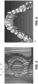
- Figure 4 shows a dense point cloud 50 generated from a structured light imaging apparatus, CS 3500 3-D camera made by Carestream Heath, Inc., Rochester NY, USA, using results from patterned illumination such as that shown in Figure 3 .
- the point cloud 50 models physical location of sampled points on tooth surfaces and other intraoral surfaces or, more generally, of surfaces of a real-world object. Variable resolution can be obtained.
- the example of Fig. 4 shows an exemplary 100 micron resolution.
- the points in the point cloud represent actual, measured points on the three dimensional surface of an object.
- the surface structure can be approximated from the point cloud representation by forming a polygon mesh, in which adjacent vertices are connected by line segments. For a vertex, its adjacent vertices are those vertices closest to the vertex in terms of Euclidean distance.
- Figure 5 shows a 3-D polygon mesh model 60 in the simple form of a triangular mesh.
- a triangular mesh forms a basic mesh structure that can be generated from a point cloud and used as a digital model to represent a 3-D object by its approximate surface shape, in the form of triangular plane segments sharing adjacent boundaries.
- Methods/apparatus for forming a polygon mesh model such as a triangular mesh or more complex mesh structure, are well known to those skilled in the contour imaging arts.
- the polygon unit of the mesh model, and relationships between neighboring polygons, can be used in embodiments of the present disclosure to extract features (e.g., curvatures, minimum curvatures, edges, spatial relations, etc.) at the teeth boundaries.
- segmentation of individual components of the image content from a digital model can be of value to the dental practitioner in various procedures, including orthodontic treatment and preparation of crowns, implants, and other prosthetic devices, for example.
- Various methods have been proposed and demonstrated for mesh-based segmentation of teeth from gums and of teeth from each other.
- drawbacks of conventional segmentation solutions include requirements for a significant level of operator skill and a high degree of computational complexity.
- Conventional approaches to the problem of segmenting tooth components and other dentition features have yielded disappointing results in many cases.
- Exemplary method and/or apparatus embodiments address such problems with segmentation that utilize the polygonal mesh data as a type of source digital model and operate in more than one stage: e.g., first, performing an automated segmentation algorithm/procedures that can provide at least a close or coarse approximation of the needed segmentation of the digital model; and second, allowing operator interactions to improve, correct and/or clean up observed errors and inconsistencies in the automated results, which can yield highly accurate results that are difficult to achieve in a purely automated manner, but not placing significant requirements on operator time or skill level and/or on needed computer resources.
- This hybrid approach in exemplary method and/or apparatus embodiments can help to combine computing and image processing power with operator perception to check, correct, and refine results of automated processing.
- the logic flow diagram of Figure 6A shows a hybrid sequence for tooth mesh segmentation and generation of a digital model to identify individual features or intraoral components such as teeth from within the mouth according to an exemplary embodiment of the present disclosure.
- an image acquisition step S 100 a plurality of structured light images of the patient's dentition are captured, providing a set of contour images for processing.
- a point cloud generation step S110 then generates a point cloud of the patient's dentition using the set of contour images.
- a polygon mesh generation step S120 forms a polygon mesh by connecting adjacent points from the point cloud results.
- a triangular mesh provides one type of polygon mesh that can be readily generated for approximating a surface contour; more complex polygon mesh configurations can alternately be used.
- segmentation step S130 is executed.
- segmentation step S130 can distinguish teeth from gum tissue, as well as distinguishing one tooth from another. Segmentation results are then displayed, showing the results of this initial, automated segmentation processing.
- the automated segmentation step S130 provides an intermediate image.
- segmentation step S130 performs the bulk of segmentation processing, but further benefits from operator review and refinements of results.
- segmentation step S130 can use any of a number of known segmentation techniques, such as fast-marching watershed algorithms, so-called snake-based segmentation, and other methods known to those skilled in the imaging arts, as noted earlier.
- Figure 6A also shows an repeat loop that enables viewer interaction with the intermediate image for refining the results of the automated segmentation processing, for example, using the basic apparatus shown in Figure 1 .
- An accept operator instructions step S140 is executed, during which the viewer indicates, on the displayed results, seed points, seed lines, block lines, boundary features, or other markings that identify one or more distinct features of the segmentation results to allow further segmentation refinement and processing.
- Viewer markup instructions cause segmentation step S130 to be executed at least a second time, this second time using input markup(s) from entered viewer instructions. It can be appreciated that different segmentation algorithms can be applied at various stages of automated or manual processing. Final results of segmentation processing are displayed and stored, and can be transmitted between computers, such as over a wired or wireless network, for example.
- tooth and gum partitioning can be automated.
- tooth and gum partitioning can use an automated curvature-based method that computes curvature of vertices in the mesh, and then uses a thresholding algorithm to identify margin vertices having large negative curvature.
- color-based segmentation can be used for tooth segmentation from the gums. This type of method can obtain average hue values from regions of the image and calculate threshold values that partition image content.
- FIG. 6B An exemplary embodiment of workflow for the hybrid tooth segmentation system is depicted in the logic flow diagram of Figure 6B .
- the control logic processor 80 ( Figure 1 ) initiates an automated segmentation step S202 in which a fully automatic tooth segmentation tool is evoked to delineate teeth and gum regions and delineate individual teeth regions.
- the fully automatic tooth segmentation tool employs exemplary algorithms such as active contour models published in the literature or otherwise well-known to those skilled in the image processing arts.
- the delineation of teeth effectively produces individually segmented teeth; however, these generated teeth may contain poorly segmented intraoral components.
- a first checking step S204 then checks for poorly segmented intraoral components.
- Checking for incorrect or incomplete segmentation in step S204 can be accomplished either computationally, such as by applying trained artificial intelligence algorithms to the segmentation results, or by viewer interaction, such as following visual inspection by the viewer.
- Figure 7A shows an exemplary poorly segmented or mis-segmented tooth 302. As shown in Figure 7A , a segmented tooth boundary 306 is not aligned with an actual tooth boundary 308.
- a primary assisted segmentation step S206 executes, activating a segmentation procedure that is also automated, but allows some level of operator adjustment.
- Primary assisted segmentation step S206 applies an algorithm for segmentation that allows operator adjustment of one or more parameters in a parameter adjustment step S210.
- Another checking step S208 executes to determine if additional segmentation processing is needed.
- the adjustable parameter can be altered computationally or explicitly by an operator instruction in step S210. Subsequent figures show an exemplary operator interface for parameter adjustment.
- An exemplary algorithm employed in primary assisted segmentation Step S206 can be a well-known technique, such as the mesh minimum curvature-based segmentation method.
- the adjustable parameter can be the threshold value of the curvature.
- the delineation of teeth performed in Step S206 may still produce poorly segmented intraoral components or features, so that a repeated segmentation process is helpful.
- the checking of poor segmentation in step S208 can be accomplished either computationally, such as by applying artificial intelligence algorithms to the segmentation results, or more directly, by visual inspection performed by the user.
- the hybrid tooth segmentation system allows the user to add exemplary geometric primitives such as seed lines on the tooth region and add blocking lines between the teeth or between the teeth and gum to aid the tooth segmentation process.
- Figure 8A shows an exemplary seed line 406 for marking a tooth, added to a mesh image 62.
- Figure 8B shows an exemplary block line 408 for indicating space between two teeth, added to a mesh image 62.
- Step S206, Step S208 and Step S210 in the Figure 6B sequence constitute an exemplary primary segmentation loop 54 that follows the fully automatic segmentation of step S202 and checking step S204.
- This exemplary primary segmentation loop 54 is intended to correct segmentation errors from the fully automated segmentation of automated segmentation step S202, as identified in step S204.
- Exemplary primary segmentation loop 54 can be executed one or more times, as needed. When exemplary primary segmentation loop 54 is successful, segmentation can be complete.
- an exemplary secondary segmentation loop 56 is used to provide more interactive segmentation approaches.
- the secondary segmentation loop 56 includes an interactive segmentation step S212, another checking step S214, and an operator markup step S216.
- Interactive segmentation step S212 activates a segmentation process that works with the operator for indicating areas of the image to be segmented from other areas.
- Interactive segmentation step S212 has an automated sequence, implemented by an exemplary algorithm such as a "fast march” method known to those skilled in the image segmentation arts.
- Step S212 may require population of the tooth region images by operator-entered seeds or seed lines or other types of geometric primitives before activation or during processing.
- seed lines or other features can be automatically generated in Step S100, S110 and S120 when the dentition mesh is entered into the system for optional operator adjustment (e.g., subsequent operations such as secondary segmentation loop 56 or Step 212).
- the features, seeds or seed lines are added to the segmentation process in operator markup Step S216 by the user.
- the results from Step S212 are subject to inspection by the user in Step S216.
- Results from the hybrid automated/interactive segmentation processing are then displayed in a display step S220, as well as stored, and can be transmitted to another computer.
- some exemplary methods/apparatus of the present disclosure provide a hybrid tooth segmentation that provides the benefits of interactive segmentation with human-machine synergy.
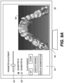
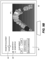
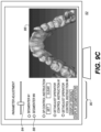
- FIGS 9A-9C show operator interface screens 52 for portions of a sequence for review and entry of markup instructions for refining mesh segmentation processing according to certain exemplary embodiments of the present disclosure.
- Interim mesh segmentation results are shown in a display area 86 on screen 52.
- a number of controls 90 for adjustment of the segmentation process are available, such as an adjustment control 84 for setting a level for overall aggressiveness or other parameter or characteristic of the segmentation processing algorithm.
- Optional selection controls 88 allow the viewer to specify one or more segmentation algorithms to be applied. This gives the operator an opportunity to assess whether one particular type of segmentation algorithm or another appear to be more successful in performing the segmentation task for the given mesh digital model. The operator can compare results against the original and adjust parameters to view results of successive segmentation attempts, with and without operator markup.
- Figure 9A also shows a trace pattern 96 that is entered as an operator seed line instruction for correcting or refining segmentation processing, as was shown previously with respect to Figure 8A .
- an operator mark in the form of trace pattern 96 or other arbitrary marking/geometric can be used to provide seed points that indicate a specific feature for segmentation, such as a molar or other tooth feature that may be difficult to process for conventional segmentation routines. Seed marks can then be used as input to a fast marching algorithm or other algorithm type, as described previously. In some cases, for example, adjacent teeth may not be accurately segmented with respect to each other; operator markup can provide useful guidance for segmentation processing where standard segmentation logic does not perform well.
- the operator can have controls 90 available that allow the entered markup to be cleared or provided to the segmentation processor.
- controls 90 color or shading can be used to differentiate various teeth or other structures identified by segmentation. Additional controls 90 can also be used to display individual segmented elements, such as individual teeth, for example.
- individual controls 90 can be used individually or in combination.
- segmentation of individual teeth from each other can use curvature thresholds to compute margin and border vertices, then use various growth techniques to define the bounds of each tooth relative to margin detection.
- controls 90 can include, but are not limited to enter/adjust seed or boundary geometrics, enter/adjust selected segmentation procedures, enter/adjust number of objects to segment, subdivide selected object, modify segmented object display, etc.
- the present disclosure can use a computer program with stored instructions that control system functions for image acquisition and image data processing for image data that is stored and accessed from an electronic memory.
- a computer program of an embodiment of the present invention can be utilized by a suitable, general-purpose computer system, such as a personal computer or workstation that acts as an image processor, when provided with a suitable software program so that the processor operates to acquire, process, transmit, store, and display data as described herein.
- a suitable, general-purpose computer system such as a personal computer or workstation that acts as an image processor
- a suitable software program so that the processor operates to acquire, process, transmit, store, and display data as described herein.
- Many other types of computer systems architectures can be used to execute the computer program of the present invention, including an arrangement of networked processors, for example.
- the computer program for performing the method of the present invention may be stored in a computer readable storage medium.
- This medium may comprise, for example; magnetic storage media such as a magnetic disk such as a hard drive or removable device or magnetic tape; optical storage media such as an optical disc, optical tape, or machine readable optical encoding; solid state electronic storage devices such as random access memory (RAM), or read only memory (ROM); or any other physical device or medium employed to store a computer program.
- the computer program for performing the method of the present invention may also be stored on computer readable storage medium that is connected to the image processor by way of the internet or other network or communication medium. Those skilled in the image data processing arts will further readily recognize that the equivalent of such a computer program product may also be constructed in hardware.
- memory can refer to any type of temporary or more enduring data storage workspace used for storing and operating upon image data and accessible to a computer system, including a database.
- the memory could be non-volatile, using, for example, a long-term storage medium such as magnetic or optical storage. Alternately, the memory could be of a more volatile nature, using an electronic circuit, such as random-access memory (RAM) that is used as a temporary buffer or workspace by a microprocessor or other control logic processor device.
- Display data for example, is typically stored in a temporary storage buffer that is directly associated with a display device and is periodically refreshed as needed in order to provide displayed data.
- This temporary storage buffer can also be considered to be a memory, as the term is used in the present disclosure.
- Memory is also used as the data workspace for executing and storing intermediate and final results of calculations and other processing.
- Computer-accessible memory can be volatile, non-volatile, or a hybrid combination of volatile and non-volatile types.
- the computer program product of the present disclosure may make use of various image manipulation algorithms and processes that are well known. It will be further understood that the computer program product embodiment of the present invention may embody algorithms and processes not specifically shown or described herein that are useful for implementation. Such algorithms and processes may include conventional utilities that are within the ordinary skill of the image processing arts. Additional aspects of such algorithms and systems, and hardware and/or software for producing and otherwise processing the images or co-operating with the computer program product of the present invention, are not specifically shown or described herein and may be selected from such algorithms, systems, hardware, components and elements known in the art.
- Exemplary embodiments according to the application can include various features described herein (individually or in combination).
Landscapes
- Engineering & Computer Science (AREA)
- Health & Medical Sciences (AREA)
- Life Sciences & Earth Sciences (AREA)
- Physics & Mathematics (AREA)
- Theoretical Computer Science (AREA)
- General Health & Medical Sciences (AREA)
- General Physics & Mathematics (AREA)
- Public Health (AREA)
- Animal Behavior & Ethology (AREA)
- Veterinary Medicine (AREA)
- Medical Informatics (AREA)
- General Engineering & Computer Science (AREA)
- Computer Vision & Pattern Recognition (AREA)
- Biophysics (AREA)
- Molecular Biology (AREA)
- Surgery (AREA)
- Pathology (AREA)
- Biomedical Technology (AREA)
- Heart & Thoracic Surgery (AREA)
- Dentistry (AREA)
- Oral & Maxillofacial Surgery (AREA)
- Human Computer Interaction (AREA)
- Epidemiology (AREA)
- Artificial Intelligence (AREA)
- Audiology, Speech & Language Pathology (AREA)
- Quality & Reliability (AREA)
- Radiology & Medical Imaging (AREA)
- Physiology (AREA)
- Psychiatry (AREA)
- Signal Processing (AREA)
- Nuclear Medicine, Radiotherapy & Molecular Imaging (AREA)
- Computer Graphics (AREA)
- Geometry (AREA)
- Software Systems (AREA)
- Rheumatology (AREA)
- Physical Education & Sports Medicine (AREA)
- Orthopedic Medicine & Surgery (AREA)
- Dental Tools And Instruments Or Auxiliary Dental Instruments (AREA)
Claims (14)
- Procédé mis en œuvre par ordinateur permettant de générer un modèle numérique d'un composant intra-oral individuel à partir d'un modèle numérique d'une dentition de patient, le procédé comprenant :l'obtention (S110, S120) d'un modèle à mailles polygonale numérique en 3D de la dentition du patient ;la réalisation (S130 ; S202, S204) d'une segmentation de composant de dent automatique sur le modèle à mailles polygonale obtenu et l'affichage de résultats de segmentation automatisée ;la réalisation d'une segmentation de dent interactive des résultats de segmentation automatisée par l'ajout, par une instruction d'opérateur, d'une ou de plusieurs primitives géométriques pour aider une segmentation de dent interactive sur les résultats de segmentation automatisée affichés, amenant une autre segmentation automatisée à être exécutée en utilisant les primitives géométriques ajoutées, et l'affichage de l'autre résultat de segmentation automatisée ;dans lequel la segmentation de dent interactive est réalisée pour un autre affinage de segmentation de manière à améliorer, corriger et/ou nettoyer des erreurs et incohérences observées dans les résultats de segmentation automatisée ;et l'affichage (S220) et le stockage des résultats de segmentation après l'affinage.
- Procédé selon la revendication 1, dans lequel les résultats de segmentation automatisée (S130 ; S202, S204) distinguent une ou plusieurs dents du tissu gingival du patient.
- Procédé selon la revendication 1, dans lequel les résultats de segmentation automatisée (S130 ; S202, S204) distinguent des dents individuelles les unes des autres.
- Procédé selon la revendication 1, dans lequel l'instruction d'opérateur (S140 ; S212, S214) identifie une dent.
- Procédé selon la revendication 1, dans lequel l'instruction d'opérateur (S140 ; S212, S214) vérifie un résultat de segmentation de dent.
- Procédé selon la revendication 1, comprenant en outre :l'acquisition (S100) d'une pluralité d'images en lumière structurée de la dentition du patient ;l'obtention (S110, S120) du modèle à mailles polygonale numérique en 3D à partir de la pluralité d'images en lumière structurée de la dentition du patient ; etla combinaison et l'alignement des résultats de segmentation des couronnes de dent individuelle avec la structure de dent et de racine individuelles du patient segmentée à partir d'une image de la dentition du patient obtenue par tomographie assistée par ordinateur à faisceau conique, CBCT.
- Procédé selon la revendication 1, dans lequel l'obtention du modèle à mailles polygonale numérique en 3D comprend l'acquisition d'une pluralité d'images en lumière structurée à partir d'une caméra intra-orale tenue à la main.
- Procédé selon la revendication 1, dans lequel les résultats d'une segmentation automatisée apparaissent en couleur.
- Procédé selon la revendication 1, dans lequel un traitement de segmentation emploie un algorithme de ligne de partage des eaux par fast marching.
- Procédé selon la revendication 1, dans lequel l'instruction d'opérateur (S140 ; S212, S214) comprend un segment de ligne tracé.
- Procédé selon la revendication 1, comprenant en outre la transmission des résultats d'une segmentation de dent interactive sur un réseau à un autre ordinateur.
- Procédé selon la revendication 1, dans lequel l'instruction d'opérateur identifie une erreur dans les résultats de segmentation automatisée affichés.
- Procédé selon la revendication 1, dans lequel le modèle à mailles polygonale numérique en 3D est une maille triangulaire.
- Appareil configuré pour générer un modèle numérique d'un composant intra-oral individuel à partir d'un modèle numérique d'une dentition de patient, comprenant :un moyen permettant d'obtenir un modèle à mailles polygonale numérique en 3D de la dentition du patient ;un moyen permettant de réaliser une segmentation de composant de dent automatique sur le modèle à mailles polygonale obtenu et d'afficher des résultats de segmentation automatisée ;un moyen permettant de réaliser une segmentation de dent interactive des résultats de segmentation automatisée par l'ajout, par une instruction d'opérateur, d'une ou de plusieurs primitives géométriques pour aider une segmentation de dent interactive sur les résultats de segmentation automatisée affichés, amenant une autre segmentation automatisée à être exécutée en utilisant les primitives géométriques ajoutées, et d'afficher l'autre résultat de segmentation automatisée ;dans lequel la segmentation de dent interactive est réalisée pour un autre affinage de segmentation de manière à améliorer, corriger et/ou nettoyer des erreurs et incohérences observées dans les résultats de segmentation automatisée ; etun moyen permettant d'afficher ou de stocker les résultats de segmentation après l'affinage.
Applications Claiming Priority (2)
| Application Number | Priority Date | Filing Date | Title |
|---|---|---|---|
| US14/851,332 US10339649B2 (en) | 2015-09-11 | 2015-09-11 | Method and system for hybrid mesh segmentation |
| PCT/US2016/049397 WO2017044347A1 (fr) | 2015-09-11 | 2016-08-30 | Procédé et système pour segmentation de grille hybride |
Publications (3)
| Publication Number | Publication Date |
|---|---|
| EP3346943A1 EP3346943A1 (fr) | 2018-07-18 |
| EP3346943C0 EP3346943C0 (fr) | 2025-05-28 |
| EP3346943B1 true EP3346943B1 (fr) | 2025-05-28 |
Family
ID=56940376
Family Applications (1)
| Application Number | Title | Priority Date | Filing Date |
|---|---|---|---|
| EP16766722.9A Active EP3346943B1 (fr) | 2015-09-11 | 2016-08-30 | Precede et system pour un segmentation hybride a mailles |
Country Status (4)
| Country | Link |
|---|---|
| US (1) | US10339649B2 (fr) |
| EP (1) | EP3346943B1 (fr) |
| ES (1) | ES3032607T3 (fr) |
| WO (1) | WO2017044347A1 (fr) |
Families Citing this family (22)
| Publication number | Priority date | Publication date | Assignee | Title |
|---|---|---|---|---|
| US11568627B2 (en) | 2015-11-18 | 2023-01-31 | Adobe Inc. | Utilizing interactive deep learning to select objects in digital visual media |
| US12097064B2 (en) * | 2016-06-17 | 2024-09-24 | Carestream Dental Technology Topco Limited | Method and system for 3D cephalometric analysis |
| WO2018033762A1 (fr) * | 2016-08-15 | 2018-02-22 | Trophy | Schéma d'arcade dentaire dynamique |
| WO2018170030A1 (fr) | 2017-03-16 | 2018-09-20 | Carestream Dental Technology Topco Limited | Procédé de montage virtuel avec dentition mixte |
| EP3595574B1 (fr) * | 2017-03-17 | 2023-08-23 | Nobel Biocare Services AG | Système et méthode automatique de cartographie d'arcade dentaire |
| ES2692425B2 (es) * | 2017-06-01 | 2019-04-03 | Padilla Pedro Perales | Procedimiento de diseno de una protesis dental mediante tecnicas digitales |
| WO2019034901A1 (fr) * | 2017-08-17 | 2019-02-21 | Trophy | Pochoir pour balayage de surface intrabuccal |
| US11244195B2 (en) * | 2018-05-01 | 2022-02-08 | Adobe Inc. | Iteratively applying neural networks to automatically identify pixels of salient objects portrayed in digital images |
| US11020206B2 (en) * | 2018-05-22 | 2021-06-01 | Align Technology, Inc. | Tooth segmentation based on anatomical edge information |
| US20230419631A1 (en) * | 2018-10-30 | 2023-12-28 | Segmentron, LLC | Guided Implant Surgery Planning System and Method |
| CN113168911A (zh) | 2018-12-21 | 2021-07-23 | 宝洁公司 | 用于操作个人梳理器具或家用清洁器具的设备和方法 |
| US12586208B2 (en) | 2018-12-21 | 2026-03-24 | The Procter & Gamble Company | Apparatus and method for operating a dental appliance |
| EP3673863A1 (fr) | 2018-12-28 | 2020-07-01 | Trophy | Optimisation d'impression 3d à l'aide d'indications cliniques |
| FR3092427B1 (fr) * | 2019-02-04 | 2022-07-08 | Borea | procédé de segmentation automatique de dents |
| US11707344B2 (en) * | 2019-03-29 | 2023-07-25 | Align Technology, Inc. | Segmentation quality assessment |
| CN110618771B (zh) * | 2019-09-20 | 2022-03-15 | 昆明闻讯实业有限公司 | 内容显示的方法、装置、终端及存储介质 |
| EP3839793A1 (fr) * | 2019-12-16 | 2021-06-23 | Dassault Systèmes | Sélection d'objets interactifs |
| US11903793B2 (en) * | 2019-12-31 | 2024-02-20 | Align Technology, Inc. | Machine learning dental segmentation methods using sparse voxel representations |
| KR102745026B1 (ko) * | 2020-01-15 | 2024-12-23 | 주식회사 메디트 | 가상 모델 생성 장치 및 방법 |
| CN113538438A (zh) * | 2020-04-21 | 2021-10-22 | 宁波深莱医疗科技有限公司 | 牙颌三维数字模型的分割方法 |
| CN113506301B (zh) * | 2021-07-27 | 2024-02-23 | 四川九洲电器集团有限责任公司 | 一种牙齿图像分割方法和装置 |
| CN113506303B (zh) * | 2021-07-27 | 2024-01-30 | 四川九洲电器集团有限责任公司 | 一种交互式牙齿分割方法、装置和处理系统 |
Citations (6)
| Publication number | Priority date | Publication date | Assignee | Title |
|---|---|---|---|---|
| WO2010077380A2 (fr) * | 2009-01-04 | 2010-07-08 | 3M Innovative Properties Company | Optimisation de trajet de caméra global |
| US20120095732A1 (en) * | 2009-03-20 | 2012-04-19 | 3Shape A/S | System and method for effective planning, visualization, and optimization of dental restorations |
| WO2012083960A1 (fr) * | 2010-12-22 | 2012-06-28 | 3Shape A/S | Système et procédé d'examen par balayage d'objets subissant des modifications |
| WO2012112867A2 (fr) * | 2011-02-18 | 2012-08-23 | 3M Innovative Properties Company | Installations orthodontiques numériques |
| US20130169639A1 (en) * | 2012-01-04 | 2013-07-04 | Feng Shi | System and method for interactive contouring for 3d medical images |
| US20130243289A1 (en) * | 2012-03-17 | 2013-09-19 | Sony Corporation | Graph cuts-based interactive segmentation of teeth in 3-d ct volumetric data |
Family Cites Families (7)
| Publication number | Priority date | Publication date | Assignee | Title |
|---|---|---|---|---|
| US6409504B1 (en) | 1997-06-20 | 2002-06-25 | Align Technology, Inc. | Manipulating a digital dentition model to form models of individual dentition components |
| US6227850B1 (en) * | 1999-05-13 | 2001-05-08 | Align Technology, Inc. | Teeth viewing system |
| AU2003245019A1 (en) * | 2002-07-22 | 2004-02-09 | Cadent Ltd. | A method for defining a finish line of a dental prosthesis |
| US7840042B2 (en) * | 2006-01-20 | 2010-11-23 | 3M Innovative Properties Company | Superposition for visualization of three-dimensional data acquisition |
| US8199988B2 (en) * | 2008-05-16 | 2012-06-12 | Geodigm Corporation | Method and apparatus for combining 3D dental scans with other 3D data sets |
| US9626462B2 (en) * | 2014-07-01 | 2017-04-18 | 3M Innovative Properties Company | Detecting tooth wear using intra-oral 3D scans |
| US9451873B1 (en) * | 2015-03-06 | 2016-09-27 | Align Technology, Inc. | Automatic selection and locking of intraoral images |
-
2015
- 2015-09-11 US US14/851,332 patent/US10339649B2/en active Active
-
2016
- 2016-08-30 EP EP16766722.9A patent/EP3346943B1/fr active Active
- 2016-08-30 ES ES16766722T patent/ES3032607T3/es active Active
- 2016-08-30 WO PCT/US2016/049397 patent/WO2017044347A1/fr not_active Ceased
Patent Citations (6)
| Publication number | Priority date | Publication date | Assignee | Title |
|---|---|---|---|---|
| WO2010077380A2 (fr) * | 2009-01-04 | 2010-07-08 | 3M Innovative Properties Company | Optimisation de trajet de caméra global |
| US20120095732A1 (en) * | 2009-03-20 | 2012-04-19 | 3Shape A/S | System and method for effective planning, visualization, and optimization of dental restorations |
| WO2012083960A1 (fr) * | 2010-12-22 | 2012-06-28 | 3Shape A/S | Système et procédé d'examen par balayage d'objets subissant des modifications |
| WO2012112867A2 (fr) * | 2011-02-18 | 2012-08-23 | 3M Innovative Properties Company | Installations orthodontiques numériques |
| US20130169639A1 (en) * | 2012-01-04 | 2013-07-04 | Feng Shi | System and method for interactive contouring for 3d medical images |
| US20130243289A1 (en) * | 2012-03-17 | 2013-09-19 | Sony Corporation | Graph cuts-based interactive segmentation of teeth in 3-d ct volumetric data |
Non-Patent Citations (2)
| Title |
|---|
| JOE MIN MOON ET AL: "Evaluation of Software Developed for Automated Segmentation of Digital Dental Models A THESIS SUBMITTED TO THE FACULTY OF THE GRADUATE SCHOOL OF THE UNIVERSITY OF MINNESOTA BY", 29 February 2012 (2012-02-29), XP055310160, Retrieved from the Internet <URL:http://conservancy.umn.edu/bitstream/handle/11299/123052/Moon_Joe Min_March2012.pdf?sequence=1&isAllowed=y> [retrieved on 20161012] * |
| SANDRO BARONE ET AL: "Creation of 3D Multi-Body Orthodontic Models by Using Independent Imaging Sensors", SENSORS, vol. 13, no. 12, 5 December 2013 (2013-12-05), CH, pages 2033 - 2050, XP055454183, ISSN: 1424-8220, DOI: 10.3390/s130202033 * |
Also Published As
| Publication number | Publication date |
|---|---|
| EP3346943C0 (fr) | 2025-05-28 |
| WO2017044347A1 (fr) | 2017-03-16 |
| ES3032607T3 (en) | 2025-07-22 |
| US10339649B2 (en) | 2019-07-02 |
| EP3346943A1 (fr) | 2018-07-18 |
| US20170076443A1 (en) | 2017-03-16 |
Similar Documents
| Publication | Publication Date | Title |
|---|---|---|
| JP7289026B2 (ja) | ハイブリッドメッシュセグメンテーションのための方法及び装置 | |
| US10339649B2 (en) | Method and system for hybrid mesh segmentation | |
| US11896455B2 (en) | Method and system for braces removal from dentition mesh | |
| JP7386215B2 (ja) | 歯列メッシュ矯正具除去のための方法および装置 | |
| US20230320818A1 (en) | Reconstruction of a virtual computed-tomography volume to track orthodontics treatment evolution | |
| US12097064B2 (en) | Method and system for 3D cephalometric analysis | |
| US20220068039A1 (en) | 3d segmentation for mandible and maxilla | |
| KR20180006917A (ko) | 교합 치아 모형의 x선 스캔을 위한 방법 및 장치 | |
| EP3185813B1 (fr) | Procédé pour une base de modèle dentaire virtuel | |
| WO2020037582A1 (fr) | Sélection de trames de clé à base de graphique destinée au balayage en 3d |
Legal Events
| Date | Code | Title | Description |
|---|---|---|---|
| STAA | Information on the status of an ep patent application or granted ep patent |
Free format text: STATUS: UNKNOWN |
|
| STAA | Information on the status of an ep patent application or granted ep patent |
Free format text: STATUS: THE INTERNATIONAL PUBLICATION HAS BEEN MADE |
|
| PUAI | Public reference made under article 153(3) epc to a published international application that has entered the european phase |
Free format text: ORIGINAL CODE: 0009012 |
|
| STAA | Information on the status of an ep patent application or granted ep patent |
Free format text: STATUS: REQUEST FOR EXAMINATION WAS MADE |
|
| 17P | Request for examination filed |
Effective date: 20180307 |
|
| AK | Designated contracting states |
Kind code of ref document: A1 Designated state(s): AL AT BE BG CH CY CZ DE DK EE ES FI FR GB GR HR HU IE IS IT LI LT LU LV MC MK MT NL NO PL PT RO RS SE SI SK SM TR |
|
| AX | Request for extension of the european patent |
Extension state: BA ME |
|
| DAV | Request for validation of the european patent (deleted) | ||
| DAX | Request for extension of the european patent (deleted) | ||
| STAA | Information on the status of an ep patent application or granted ep patent |
Free format text: STATUS: EXAMINATION IS IN PROGRESS |
|
| 17Q | First examination report despatched |
Effective date: 20200706 |
|
| RAP1 | Party data changed (applicant data changed or rights of an application transferred) |
Owner name: CARESTREAM DENTAL LLC |
|
| RAP1 | Party data changed (applicant data changed or rights of an application transferred) |
Owner name: DENTAL IMAGING TECHNOLOGIES CORPORATION |
|
| GRAP | Despatch of communication of intention to grant a patent |
Free format text: ORIGINAL CODE: EPIDOSNIGR1 |
|
| RIC1 | Information provided on ipc code assigned before grant |
Ipc: G06T 7/155 20170101ALI20241114BHEP Ipc: G06T 7/12 20170101ALI20241114BHEP Ipc: A61C 7/00 20060101ALI20241114BHEP Ipc: G06T 7/00 20170101ALI20241114BHEP Ipc: A61C 11/00 20060101AFI20241114BHEP |
|
| STAA | Information on the status of an ep patent application or granted ep patent |
Free format text: STATUS: GRANT OF PATENT IS INTENDED |
|
| INTG | Intention to grant announced |
Effective date: 20241219 |
|
| GRAS | Grant fee paid |
Free format text: ORIGINAL CODE: EPIDOSNIGR3 |
|
| GRAA | (expected) grant |
Free format text: ORIGINAL CODE: 0009210 |
|
| STAA | Information on the status of an ep patent application or granted ep patent |
Free format text: STATUS: THE PATENT HAS BEEN GRANTED |
|
| AK | Designated contracting states |
Kind code of ref document: B1 Designated state(s): AL AT BE BG CH CY CZ DE DK EE ES FI FR GB GR HR HU IE IS IT LI LT LU LV MC MK MT NL NO PL PT RO RS SE SI SK SM TR |
|
| REG | Reference to a national code |
Ref country code: GB Ref legal event code: FG4D |
|
| REG | Reference to a national code |
Ref country code: CH Ref legal event code: EP |
|
| REG | Reference to a national code |
Ref country code: DE Ref legal event code: R096 Ref document number: 602016092396 Country of ref document: DE |
|
| REG | Reference to a national code |
Ref country code: IE Ref legal event code: FG4D |
|
| REG | Reference to a national code |
Ref country code: ES Ref legal event code: FG2A Ref document number: 3032607 Country of ref document: ES Kind code of ref document: T3 Effective date: 20250722 |
|
| U01 | Request for unitary effect filed |
Effective date: 20250619 |
|
| U07 | Unitary effect registered |
Designated state(s): AT BE BG DE DK EE FI FR IT LT LU LV MT NL PT RO SE SI Effective date: 20250630 |
|
| U20 | Renewal fee for the european patent with unitary effect paid |
Year of fee payment: 10 Effective date: 20250709 |
|
| PGFP | Annual fee paid to national office [announced via postgrant information from national office to epo] |
Ref country code: ES Payment date: 20250909 Year of fee payment: 10 |
|
| PG25 | Lapsed in a contracting state [announced via postgrant information from national office to epo] |
Ref country code: GR Free format text: LAPSE BECAUSE OF FAILURE TO SUBMIT A TRANSLATION OF THE DESCRIPTION OR TO PAY THE FEE WITHIN THE PRESCRIBED TIME-LIMIT Effective date: 20250829 Ref country code: NO Free format text: LAPSE BECAUSE OF FAILURE TO SUBMIT A TRANSLATION OF THE DESCRIPTION OR TO PAY THE FEE WITHIN THE PRESCRIBED TIME-LIMIT Effective date: 20250828 |
|
| PG25 | Lapsed in a contracting state [announced via postgrant information from national office to epo] |
Ref country code: PL Free format text: LAPSE BECAUSE OF FAILURE TO SUBMIT A TRANSLATION OF THE DESCRIPTION OR TO PAY THE FEE WITHIN THE PRESCRIBED TIME-LIMIT Effective date: 20250528 |
|
| PG25 | Lapsed in a contracting state [announced via postgrant information from national office to epo] |
Ref country code: HR Free format text: LAPSE BECAUSE OF FAILURE TO SUBMIT A TRANSLATION OF THE DESCRIPTION OR TO PAY THE FEE WITHIN THE PRESCRIBED TIME-LIMIT Effective date: 20250528 |
|
| PGFP | Annual fee paid to national office [announced via postgrant information from national office to epo] |
Ref country code: CH Payment date: 20250901 Year of fee payment: 10 |
|
| PG25 | Lapsed in a contracting state [announced via postgrant information from national office to epo] |
Ref country code: RS Free format text: LAPSE BECAUSE OF FAILURE TO SUBMIT A TRANSLATION OF THE DESCRIPTION OR TO PAY THE FEE WITHIN THE PRESCRIBED TIME-LIMIT Effective date: 20250828 |
|
| PG25 | Lapsed in a contracting state [announced via postgrant information from national office to epo] |
Ref country code: IS Free format text: LAPSE BECAUSE OF FAILURE TO SUBMIT A TRANSLATION OF THE DESCRIPTION OR TO PAY THE FEE WITHIN THE PRESCRIBED TIME-LIMIT Effective date: 20250928 |
|
| PG25 | Lapsed in a contracting state [announced via postgrant information from national office to epo] |
Ref country code: SM Free format text: LAPSE BECAUSE OF FAILURE TO SUBMIT A TRANSLATION OF THE DESCRIPTION OR TO PAY THE FEE WITHIN THE PRESCRIBED TIME-LIMIT Effective date: 20250528 |
|
| PG25 | Lapsed in a contracting state [announced via postgrant information from national office to epo] |
Ref country code: CZ Free format text: LAPSE BECAUSE OF FAILURE TO SUBMIT A TRANSLATION OF THE DESCRIPTION OR TO PAY THE FEE WITHIN THE PRESCRIBED TIME-LIMIT Effective date: 20250528 |
|
| PG25 | Lapsed in a contracting state [announced via postgrant information from national office to epo] |
Ref country code: SK Free format text: LAPSE BECAUSE OF FAILURE TO SUBMIT A TRANSLATION OF THE DESCRIPTION OR TO PAY THE FEE WITHIN THE PRESCRIBED TIME-LIMIT Effective date: 20250528 |
|
| PG25 | Lapsed in a contracting state [announced via postgrant information from national office to epo] |
Ref country code: MC Free format text: LAPSE BECAUSE OF FAILURE TO SUBMIT A TRANSLATION OF THE DESCRIPTION OR TO PAY THE FEE WITHIN THE PRESCRIBED TIME-LIMIT Effective date: 20250528 |
|
| PLBE | No opposition filed within time limit |
Free format text: ORIGINAL CODE: 0009261 |
|
| STAA | Information on the status of an ep patent application or granted ep patent |
Free format text: STATUS: NO OPPOSITION FILED WITHIN TIME LIMIT |
|
| REG | Reference to a national code |
Ref country code: CH Ref legal event code: L10 Free format text: ST27 STATUS EVENT CODE: U-0-0-L10-L00 (AS PROVIDED BY THE NATIONAL OFFICE) Effective date: 20260409 |
|
| GBPC | Gb: european patent ceased through non-payment of renewal fee |
Effective date: 20250830 |
|
| 26N | No opposition filed |
Effective date: 20260303 |