EP3347128B1 - Anordnung mit trägersubstrat für flüssigkeitsprobe und verwendung davon - Google Patents
Anordnung mit trägersubstrat für flüssigkeitsprobe und verwendung davon Download PDFInfo
- Publication number
- EP3347128B1 EP3347128B1 EP16760485.9A EP16760485A EP3347128B1 EP 3347128 B1 EP3347128 B1 EP 3347128B1 EP 16760485 A EP16760485 A EP 16760485A EP 3347128 B1 EP3347128 B1 EP 3347128B1
- Authority
- EP
- European Patent Office
- Prior art keywords
- grooves
- cavity
- groove
- substrate
- microns
- Prior art date
- Legal status (The legal status is an assumption and is not a legal conclusion. Google has not performed a legal analysis and makes no representation as to the accuracy of the status listed.)
- Active
Links
Images


Classifications
-
- B—PERFORMING OPERATIONS; TRANSPORTING
- B01—PHYSICAL OR CHEMICAL PROCESSES OR APPARATUS IN GENERAL
- B01L—CHEMICAL OR PHYSICAL LABORATORY APPARATUS FOR GENERAL USE
- B01L3/00—Containers or dishes for laboratory use, e.g. laboratory glassware; Droppers
- B01L3/50—Containers for the purpose of retaining a material to be analysed, e.g. test tubes
- B01L3/508—Rigid containers without fluid transport within
- B01L3/5088—Rigid containers without fluid transport within confining liquids at a location by surface tension, e.g. virtual wells on plates, wires
-
- G—PHYSICS
- G01—MEASURING; TESTING
- G01N—INVESTIGATING OR ANALYSING MATERIALS BY DETERMINING THEIR CHEMICAL OR PHYSICAL PROPERTIES
- G01N21/00—Investigating or analysing materials by the use of optical means, i.e. using sub-millimetre waves, infrared, visible or ultraviolet light
- G01N21/01—Arrangements or apparatus for facilitating the optical investigation
-
- G—PHYSICS
- G02—OPTICS
- G02B—OPTICAL ELEMENTS, SYSTEMS OR APPARATUS
- G02B21/00—Microscopes
- G02B21/34—Microscope slides, e.g. mounting specimens on microscope slides
-
- B—PERFORMING OPERATIONS; TRANSPORTING
- B01—PHYSICAL OR CHEMICAL PROCESSES OR APPARATUS IN GENERAL
- B01L—CHEMICAL OR PHYSICAL LABORATORY APPARATUS FOR GENERAL USE
- B01L2200/00—Solutions for specific problems relating to chemical or physical laboratory apparatus
- B01L2200/06—Fluid handling related problems
- B01L2200/0684—Venting, avoiding backpressure, avoid gas bubbles
-
- B—PERFORMING OPERATIONS; TRANSPORTING
- B01—PHYSICAL OR CHEMICAL PROCESSES OR APPARATUS IN GENERAL
- B01L—CHEMICAL OR PHYSICAL LABORATORY APPARATUS FOR GENERAL USE
- B01L2300/00—Additional constructional details
- B01L2300/08—Geometry, shape and general structure
- B01L2300/0809—Geometry, shape and general structure rectangular shaped
- B01L2300/0822—Slides
-
- B—PERFORMING OPERATIONS; TRANSPORTING
- B01—PHYSICAL OR CHEMICAL PROCESSES OR APPARATUS IN GENERAL
- B01L—CHEMICAL OR PHYSICAL LABORATORY APPARATUS FOR GENERAL USE
- B01L2300/00—Additional constructional details
- B01L2300/08—Geometry, shape and general structure
- B01L2300/089—Virtual walls for guiding liquids
-
- B—PERFORMING OPERATIONS; TRANSPORTING
- B01—PHYSICAL OR CHEMICAL PROCESSES OR APPARATUS IN GENERAL
- B01L—CHEMICAL OR PHYSICAL LABORATORY APPARATUS FOR GENERAL USE
- B01L2300/00—Additional constructional details
- B01L2300/16—Surface properties and coatings
- B01L2300/161—Control and use of surface tension forces, e.g. hydrophobic, hydrophilic
-
- B—PERFORMING OPERATIONS; TRANSPORTING
- B01—PHYSICAL OR CHEMICAL PROCESSES OR APPARATUS IN GENERAL
- B01L—CHEMICAL OR PHYSICAL LABORATORY APPARATUS FOR GENERAL USE
- B01L2400/00—Moving or stopping fluids
- B01L2400/04—Moving fluids with specific forces or mechanical means
- B01L2400/0403—Moving fluids with specific forces or mechanical means specific forces
- B01L2400/0406—Moving fluids with specific forces or mechanical means specific forces capillary forces
Definitions
- the invention relates to an assembly for optical analysis of a liquid sample comprising a micro-structured substrate for supporting the liquid sample covered by a coverslip and to a use of such an assembly for carrying out analysis of a liquid sample. .
- particles of interest In many fields of research and analysis, it is sought to determine the presence or absence of certain particles called "particles of interest” in a liquid and / or to study the development of these particles of interest present in the liquid. this liquid and / or to promote the formation of structures from the particles present in the liquid.
- These particles can be on the one hand biological objects such as cells (animal and / or plant, living and / or non-living), antibodies, proteins, viruses, etc ... and / or on the other hand non-biological objects such as molecules said to be of interest, in particular chemical molecules, in particular polymers, liquids, etc.
- a sample support which frequently consists of a parallelepipedal glass slide and an observation instrument such as a microscope, spectrum analyzer, fluorescence quantification system, etc.
- the sample is deposited on the glass slide, then a glass coverslip is delicately deposited on the sample as illustrated on the figures 3a to 3c of this text, so as not to enclose an air bubble between the lower surface of the coverslip and the sample nor to damage any particles present in the sample, the coverslip then being held by capillary action on the glass slide .
- it can be fixed on the glass slide by gluing, generally using a wax, in particular in order to enclose the sample and prevent the latter from evaporating which could occur during observations. continues in particular of long duration and / or when the sample is subjected to temperature variations, in particular temperature rises.
- the bonding technique makes it possible, on the one hand, to avoid or limit the movement of the liquid in the sample analysis zone and, on the other hand, to avoid a variation in concentration in particles and / or salts optionally dissolved in the sample, which allows observation of the particles under stabilized conditions.
- US-A-2041290 describes a sample holder in the form of a plate for the analysis of a liquid sample, for example a drop of blood, on the upper surface of which are provided a plurality of wells of circular shape, each well being surrounded a channel provided for collecting the excess liquid of the sample to be analyzed deposited in said well.
- US-A-2302830 describes a plate of the same type in which the well is formed by depositing a circular bead of material on the surface of the wafer, this bead being surrounded by a circular groove engraved on the surface of the wafer in order to collect the excess liquid to analyze.
- US-A-5948685 proposes to use a device made up of a glass slide for a microscope on which is structured a containment barrier whose thickness is less than 1 ⁇ m, so as to create a well on the surface of the slide.
- a containment barrier whose thickness is less than 1 ⁇ m, so as to create a well on the surface of the slide.
- the sample being placed inside this well, any overflow is in principle stopped, which makes it possible to avoid the effects of loss of liquid at the edges of the slide.
- the volume of the sample is poorly controlled, that is to say too high, this barrier is not sufficient to prevent leaks at the edges.
- the coverslip that is placed on the sample has a great affinity with the liquid sample, which is often the case and if it is not deposited strictly parallel to the slide, a phenomenon overflow of the liquid takes place along this lamella.
- WO 82/02958 describes a support plate for the analysis of liquid samples, this plate comprising a plurality of assemblies provided for depositing a drop of liquid sample, each assembly consisting of a central well surrounded by a channel or groove capable of receiving the excess liquid deposited in the central well.
- US2014 / 106395 describes suspended drop carrier plates used for cell culture. These supports have a plurality of wells surrounded by grooves. The function of the grooves described in this document is to keep the drop of liquid in the well when this support plate is turned over to produce this set of suspended drops.
- JP 2002350305 describes a plate with a sample immersed in a reagent, the reagent being stored at a storage groove in order to prevent the sample from drying out.
- US-A-7138270 described in particular in fig.8 a liquid sample support comprising a plurality of circular wells regularly distributed over the upper surface of the support.
- the typical height of the side walls of the wells is between 30 and 200 ⁇ m, all of these wells being surrounded by an external confinement barrier.
- This type of configuration makes it possible to fill the wells completely with the aid of an excess of liquid which is expelled during the installation of the upper coverslip, in the intermediate zone located between the different wells and delimited by a on the one hand by the side walls of the various wells and on the other hand by the external confinement barrier.
- This external barrier helps contain excess liquid to prevent any leakage outside the slide and coverslip.
- the positioning of the excess liquid is however not controlled and the coverslip must be placed in an appropriate manner in order to limit cross-contamination between the wells. Indeed, as long as the upper coverslip is not hermetically sealed to the structures of the wells, a part of the excess liquid can be drained by capillary action out of a well in an uncontrolled manner. This has the consequence of generating a bubble within one or more wells (if the quantity of liquid drained is too large) and the diffusion of particles from one well to another when the exhaust liquids from two wells consecutive mingle, contaminant thus the subsequent analysis of initially independent wells.
- the slightest dust or particle coming from the sample coming to be inserted between the barrier and the upper lamella or the slightest irregularity in the barrier is at the origin of a privileged uncontrollable evaporation zone which limits reproducibility. analysis, particularly when the latter is long and needs to be carried out at high temperatures. This configuration is therefore unreliable for routine analyzes even if it is carried out with particularly reproducible (and therefore expensive) technologies.
- US-A-2003/0194709 describes a method for producing a substrate comprising electrodes made of hydrophilic material partially surrounded by hydrophobic zones in order to carry out an electrochemical analysis of a DNA-type sample.
- the use of such a substrate does not require the use of a protective cover deposited on the liquid sample, this cover being used only for carrying out optical analyzes of a sample.
- a protective cover deposited on the liquid sample, this cover being used only for carrying out optical analyzes of a sample.
- None of the aforementioned systems therefore makes it possible to provide a satisfactory solution to the problem of positioning and maintaining a liquid sample in a fine cavity, which allows precise lateral positioning of the sample, excellent fluidic and chemical stability of the sample. in the measurement area, as well as an absence of cross-contamination in the case of positioning several samples on the rack, regardless of user dexterity and sample volume accuracy.
- An object of the invention consists of an assembly comprising a substrate of the micro-structured type which does not have the drawbacks of the supports of the prior art and makes it possible in particular to prevent the formation of a bubble in the liquid sample during the closing the support cavity with a coverslip after depositing the sample in the cavity.
- the assembly for optical analysis of a liquid sample is characterized in that it comprises a micro-structured substrate for supporting the liquid sample comprising a lower face and an upper face which comprises, on the one hand, at least one surface cavity of volume V0 opening onto said upper face and forming an analysis zone for the liquid sample and on the other hand, a first groove of a first volume V1, arranged around each surface cavity and opening out on its upper face as well as at least one second groove opening onto its upper face and arranged around the first groove, the sum of the volumes of the second grooves being equal to V2, the volume V1 + V2 being greater than or equal to 0.05 V0, preferably 0.1 V0, the depth of the grooves being greater than 10 microns and less than 500 microns, preferably between 20 microns and 500 microns, the grooves being continuous and / or not communicating with each other, substrate on which is deposited in at least one cavity, at least one liquid sample of volume greater than the sum of the volumes of the cavity and of the first groove, substrate which is covered by
- the volume V1 + V2 is greater than or equal to 0.2 V0, more preferably greater than or equal to 0.3 V0.
- the substrate according to the invention is characterized in that it comprises a total of n grooves, with n> 2, each groove of rank p greater than or equal to 2 and less than or equal to n being arranged around the row groove (p-1), the total volume V3 of the (n-1) first grooves being greater than or equal to 0.05 V0.
- the substrate according to the invention will have n grooves, n being less than or equal to 100, preferably less than or equal to 10.
- the section of each of the grooves will be substantially identical and / or preferably constant or substantially constant: the substrate will for example comprise n concentric circular grooves of the same section, preferably arranged at an equal distance from each other.
- the section of at least one of the grooves preferably the nth or last groove (the outermost) will be greater than that of the other grooves, preferably greater than or equal to 5 times, more preferably 10 times the section of the (n-1) th groove.
- the additional benefit of an nth groove with a volume appreciably greater or much greater than that of the (n-1) th groove, is to make it possible to avoid, in the vast majority of cases, an overflow of the sample liquid beyond of this nth groove, in particular when a support is available comprising a plurality of cavities, each of them being surrounded by a plurality of grooves, for example the same number n of grooves.
- the substrate according to the invention has at least six, preferably at least eight surface cavities, each cavity having a diameter of approximately 5 mm and a depth of between 20 microns and 500 microns and being distant about 5 mm from another cavity, each cavity being surrounded by a series of 5 to 10 grooves about 100 microns in depth, spaced from each other by about 100 microns.
- the grooves be continuous and / or that they do not communicate (fluidly) with each other in order to avoid any flow by capillary action between the grooves and consequently the formation of bubbles. in the central cavity.
- the presence of at least one second continuous groove (and / or not communicating fluidly with the other grooves) arranged around the first groove made it possible to ensure a regularly distributed flow ( 360 degrees) of liquid from the cavity to at least the second groove thus avoiding the "wedge effect" present when closing the cavity with a cover slip.
- the presence of at least one second groove prevents this bubble from appearing in the cavity, or sample viewing area.
- the presence of multiple grooves thus avoids over-emptying the cavity and causing the appearance of an air bubble. under the coverslip.
- the distance between the first groove and the second groove will be substantially constant (for example in the case of a first circular groove, the second groove will preferably also be circular, the two grooves being concentric). This further improves the results obtained.
- these grooves without necessarily being of exactly constant section over their whole, will generally have a substantially constant section so as not to create and / or promote privileged passages for the liquid during the flow of the latter from the cavity towards the first groove and from the first groove towards the second groove, promoting the symmetry of the whole cavity and grooves.
- the shape of the cavity in particular the shape of the contour of the cavity when it opens onto the upper surface of the support, can be arbitrary but will preferably be in the form of a bowl with walls preferably substantially vertical or inclined towards the side. inside the cavity and the contour of which will preferably be substantially symmetrical with respect to an axis perpendicular to the upper face of the support (generally flat).
- the preferred outline will be circular, rectangular or square.
- at least the first groove will have the same shape as the contour of the cavity, positioned substantially at an equal distance therefrom.
- the surface located on the upper face of the substrate, between the contour of the cavity and the internal contour of the first groove will preferably be a flat or substantially flat surface, preferably oriented parallel to the lower face of the support, itself generally flat.
- This surface (hereinafter referred to as the first surface) may either retain its surface properties (for example hydrophilic or hydrophobic) inherent to the shape initially chosen for this surface and / or to the material used for the substrate or its upper layer (- see below for example the case of the substrate whose cavity and barriers are created by selective deposition of a layer of material -), either be specially treated to give it surface properties different from those of the material used (for example, to make it hydrophilic if it is hydrophobic or vice versa, or else to reduce and / or increase its hydrophilic or hydrophobic character).
- surface properties for example hydrophilic or hydrophobic
- any surface or surface portion of the substrate intended in particular to be in contact with the liquid sample in order to modify its capillary properties, in particular the angle of contact of the liquid with said surface.
- capillary barrier will thus be referred to as any deformation of the surface or of a surface portion of the substrate which is intended, when the latter is used, to be in contact with the liquid of a sample, that this deformation results from a treatment of the surface and / or a modification of the shape of the surface, in particular the appearance of convex shapes thereon.
- the support is characterized in that at least certain zones of the upper face and / or of the cavity and / or of the grooves are treated so as to modify the properties of the capillary barrier in these zones. inherent in the surface condition of the support material and / or in the geometry of the grooves and surfaces.
- the section of the grooves can be any but will be according to different preferred variants, preferably rectangular, square, trapezoidal, triangular, etc.
- the shape of the section of a groove can in particular be chosen as a function of the value of the angle (convex) formed by the side wall of the groove and the surface of the upper face at the level of the substrate (value of the angle convex edge) so as to modify the capillary barrier created by this convex surface which connects the grooves (or the cavity) to the upper face of the substrate.
- the material of the support can be not only glass usually used for these analysis plates but can also consist of any thermoplastic material, thermosetting, transparent or not, as well as ceramic materials, or others.
- the dimensions of the grooves can be very varied depending on the intended use of the support.
- the width and depth of the grooves may vary between 10 microns and 500 microns, preferably between 20 microns and 500 microns.
- the distance between the internal contour of a groove with the external contour of the preceding groove which it surrounds and / or the cavity is between approximately 1 micron and 1 mm, preferably equal to approximately 100 microns.
- the substrate consists of a single-layer or multi-layer material in which at least one of the grooves and / or the cavity is etched or formed thermally, mechanically and / or chemically.
- the substrate is composed of at least a first lower layer on which is deposited a second upper layer from which are produced the side walls of the cavity and / or grooves, the side walls of which are thus arranged in protrusion from the lower layer.
- the grooves can be produced by selective deposition of at least one resin or by vacuum deposition of the PVD, CVD, PECVD, etc. type.
- the manufacture of the grooves and / or the cavity does not pose any particular problem: it suffices to use the forming methods well known and identified for the material used: mechanical forming, thermomechanical, chemical etching (selective etching using 'a masking technique), etching using a laser, as well as all the techniques of selective deposition of materials on a support when creating the cavity and / or the grooves by a deposition technique (for example coating through a silk screen, chemical deposition, vacuum deposition such as CVD, PVD, etc.).
- the cavity and / or the grooves are not created by removing material on and from the upper surface of the support but by adding of a material identical to or different from that constituting the support to create physical barriers which delimit the cavity and / or the peripheral grooves.
- the terms cavity and grooves will be used to denote respectively the volume trapped inside the first physical barrier (which is therefore continuous in this variant) and the volumes trapped between the other barriers arranged around the first. barrier and therefore around the central cavity (this variant is illustrated in particular in the figures below)
- the spreading zone 3 of the liquid sample 1 respects the envelope delimited by the grooves, thus making it possible to center the sample in a zone of analysis chosen and not random and also limiting the risk of sample loss by leakage.
- the support according to the invention there are structures comprising two or three grooves arranged around the central cavity, these grooves being preferably similar, that is to say preferably having the same cross section, as well as the structures in which the last groove has a section greater than that of the other grooves.
- the volume of the liquid sample dispensed in the cavity is preferably slightly greater than the volume of the cavity without, however, overflowing from this cavity thanks to the liquid meniscus which forms at the top of the cavity.
- the manipulator it is necessary for the manipulator to be well trained or else it will be necessary to have an automated system for delivering a calibrated volume, commercially available systems such as automatic pipettes.
- the volume of the grooves is such as to allow the excess volume of liquid deposited in the central cavity to be contained when a cover slip is placed on the substrate.
- the grooves will be continuous and separated from each other. Although two or more wells and / or grooves can be made to communicate with each other and in particular several well between them and provide a set of grooves which surround the plurality of wells (as for example shown in Fig. 6 of the present application or the grooves are common to several cavities), it will be preferable not to provide liquid communication between the various grooves, between themselves and / or with at least one cavity.
- the substrate defined above as well as the analysis assembly find their use in particular for carrying out analysis of a liquid sample and in particular by using the amplification technique called “PCR” (or “Polymerase Chain Reaction”) .
- the figure 1 presents a schematic sectional view of an exemplary embodiment of the support according to the invention in end use on which is shown a schematic sectional view of the assembly according to the invention consisting of a micro-structured substrate 10 composed of a thick material comprising a lower face 11 and an upper face 17 onto which opens a network of surface cavities.
- This network of surface cavities is composed of a first surface cavity 12 called the “analysis zone” intended to receive the liquid sample. 1 to be analyzed, above which is placed according to the present example a conventional microscopy system via a microscope objective 2.
- the network of surface cavities further comprises a plurality of grooves 13, 14, 15, 16 forming a so-called “escape zone” intended to collect the excess sample 1 initially deposited by the user in the analysis zone and / or when placing the transparent plate 30 on the support at the level of the analysis area.
- the exhaust zone consists of a set of grooves preferably arranged concentrically when the central cavity 12 has a center of symmetry.
- the grooves hereinafter also called “exhaust passages” are in this example four in number and such that the groove 16 surrounds the groove 15 which surrounds the groove 14 which surrounds the groove 13 which itself surrounds the central cavity 12. or analysis area.
- the exhaust corridor 13 constitutes the exhaust corridor hereinafter called “primary”, that is to say surrounding only the cavity or analysis zone 12. (the other exhaust corridors 14, 15, 16 are hereinafter called “secondary”, that is to say surrounding the analysis zone 12 and the primary exhaust passage 13).
- the section of the grooves is substantially identical.
- the cavity and grooves assembly is in this example surmounted by a closure plate 30 composed of a microscope slide 150 ⁇ m thick, thus forming a set of unrelated cavities.
- the set of cavities and grooves has separation surfaces 20, 21, 22, 23 (extending by a surface 24) that are similar or different.
- a method, for example, for producing a microstructured substrate according to this figure consists in choosing for the material of thickness a microscope slide, for example of dimensions 26 mm ⁇ 76 mm in plastic material such as polystyrene, to apply pressure to the using a parallelepipedal metal part, on one of the surfaces of the strip which will in fact be the upper surface 17 of the micro-structured substrate, the lower surface 11 being supported by a flat metal part preferably covering the entire substrate.
- the two metal parts In heating the two metal parts to a temperature close to the glass transition temperature (95 ° C) of the chosen material and applying pressure on the metal parallelepiped greater than 1 bar, the latter will sink into the polystyrene strip by a few tens of microns as a function of time and pressure.
- the nested structure of the grooves makes it possible to control the spreading zone of the liquid sample 1 between the micro-structured substrate.
- the same structure can be produced according to the invention by depositing the containment barriers 20, 21, 22 and 23 on a support and thus create a relief.
- the convex surfaces formed by the ridges delimiting the grooves 13, 14, 15, 16 form capillary barriers whose properties are inherent to the geometry and / or to the materials and surface treatments used to produce the support.
- the properties of these capillary barriers can be modified by modifying the geometry of the grooves, and in particular of their edges and / or by treating them locally (partially or totally) and / or the surfaces which surround them, as has been done. been explained above.
- the figures 2a to 2d schematically illustrate the steps for filling the network of surface cavities / grooves during standard use by an experimenter, for example in biology.
- This example also illustrates another embodiment of a micro structured substrate according to the invention, in which the network of micro surface cavities is produced by a photolithographic process as described for example in the book by Sami Franssila "Introduction to Microfabrication ”, Wiley in a layer of micro-structured material overlying a planar thickness material.
- This manufacturing process has the advantage, compared to the thermoforming technique described above, of making it possible to combine different materials in contact with the liquid sample 1.
- the first step of filling the fine analysis cavity is shown: it corresponds to the deposition of the liquid sample 1 on the micro-structured substrate.
- the user using, for example, a micropipette deposits a volume of liquid sample 1 greater than the sum of the volumes of the analysis zone 12 and of the primary exhaust corridor 13.
- the lateral extension of the liquid sample is then either limited by the outer envelope of the analysis zone (negative capillary barrier or low affinity), or by the 'inner envelope of the cavity forming the primary exhaust passage 13 or first groove (positive capillary barrier or strong affinity).
- the volume of liquid delivered by the user must remain below a critical volume which depends on the affinity of the liquid sample with the layer of micro-structured material.
- a hydrophobic material such as an epoxy-type resin such as the SU-8 resin (described as well as its implementation in the patent US 4882245 ) improves the retention force of the liquid sample during the liquid distribution step and therefore the maximum volume delivered.
- negative capillary barriers are thus created between the external contour of the cavity and the internal contour of the first groove, between the external contour of the first groove and the internal contour of the second groove, etc ..., these negative capillary barriers all of the same nature in this example, being the separation surfaces 20, 21, 22, 23, 24, and the convex surfaces of the edges of the grooves which are attached thereto.
- the user then closes the assembly consisting of the micro-structured substrate, the liquid sample 1 and a coverslip constituting the closure substrate 30 in order to finalize the formatting of an analysis assembly comprising the substrate 10, the liquid 1 to be analyzed and the cover slide 30.
- the evolution of the liquid sample 1 within the holding structure is represented successively by the figures 2b, 2c and 2d on which the gradual lowering of the slide 30 allows the liquid 1 to flow at least in the grooves 13 and 14 while preventing the formation of a bubble in the sample when the assembly is closed.
- the excess volume of liquid sample becomes too large to remain above the analysis zone 12.
- the pressure exerted on the liquid by the closure substrate 30 then pushes the liquid sample 1 to cross the capillary barrier linked to the surface 20 and fills the groove 13, which abruptly reduces the quantity of excess liquid sample.
- the sample spreading zone then covers the analysis zone and the primary exhaust passage 13, the liquid being temporarily stopped by the new capillary barrier 21 between the primary 13 and secondary 14 passages.
- the holding substrate 10 consists of a silica glass microscope slide on which has been deposited a micro-structured layer of photosensitive resin SU8 50 ⁇ m thick defining an analysis zone (cavity) 12 with a total volume substantially equal to 5 ⁇ L over a circular area of 1 cm 2 and surrounded by a series of two grooves, the first groove having a rectangular section 50 ⁇ m deep and 200 ⁇ m wide, i.e. a volume of 0 , 4 ⁇ L, (i.e. 0.08 times the volume of the cavity), the second groove having a depth of 50 ⁇ m and a width of 5 mm, i.e.
- a volume of 15 ⁇ L the two grooves and the cavity being respectively separated from each other by a distance of 200 ⁇ m. It is observed that in general, the repetition of the grooves in accordance with the invention makes it possible to avoid the appearance of a bubble in the analysis zone both for small volumes of liquid (5 ⁇ L) and for larger volumes (up to 20 ⁇ L in this example).
- the contact angle of the drop delivered into the analysis zone is greater than 70 °, which characterizes a hydrophobic material (the SU-8 resin).
- This example of a substrate according to the invention allows the precise positioning and maintenance of an analysis zone in the form of a cavity, without bubbles, preventing any overflow of the liquid sample outside the cavity of the micro-structured zone. This type of substrate allows controlling the thickness of the analysis cavity by controlling the height of the structured layer.
- the hydrophobic material constituting the structured layer makes it possible to contain a larger excess volume than in the case of a hydrophilic structured layer
- the use of a material of hydrophilic thickness allows on the other hand, to improve the rapidity of filling successive grooves and therefore minimizes the probability of formation of bubbles in the grooves when the user closes too quickly.
- the filling of several grooves is particularly recommended to limit the problems of evaporation of the liquid sample in the analysis zone.
- the succession of grooves filled with the excess liquid constitutes a barrier to evaporation which is all the more effective as the number of cavities and the filling of the cavities is large. It is another advantage of the invention to use a plurality of grooves which make it possible to obtain a liquid barrier surrounding the analysis zone and therefore to prevent, as long as this liquid barrier is intact, evaporation in the zone. analysis at the origin of fluidic or chemical instabilities.
- Example 1 The support of Example 1 was used to carry out an example of experiments showing that the zone for spreading the liquid sample 1 on a substrate according to the invention is stable: the support assembly plus liquid sample trapped by the coverslip 30 was subjected to heating at 50 ° C. for 30 minutes: no significant evaporation of the liquid sample located in the analysis zone was observed. This was not affected by the evaporation process. In comparison, a slide-coverslip system without microstructures sees the same amount of liquid sample completely evaporated after only 20 min.
- the succession of grooves therefore constitute a barrier to evaporation and makes it possible to keep the analysis zone intact.
- each groove even empty, constitutes a buffer zone where the humidity rate can increase to saturation.
- evaporation is all the faster in the analysis zone as the process takes place by contact with the outside air directly.
- the slightest defect in the containment barrier or the slightest dust at this level also dramatically increases the evaporation of the liquid sample.
- the multiplication of intermediate cavities between the analysis zone and the outside slows down the evaporation process.
- This example describes the production of a micro-structured substrate according to the invention comprising several surface cavities, each cavity being surrounded by a plurality of grooves (there is not necessarily, although preferably, the same number of grooves around each cavity).
- a coverslip of the usual size (2.54 cm X 5.08 cm) for example made of synthetic material of the PS or PMMA type two parallel rows of four circular wells (cavities) of 5 mm in diameter are produced by molding or stamping. 25 microns deep (i.e. a volume V0 of 0.5 microliter). Each well is separated from the previous well in the row by 5 mm (distance between the perimeters of the cavities).
- Each well is surrounded by a series of 5 to 10 grooves 100 microns deep spaced from each other by 100 microns.
- a series of 5 grooves thus corresponds to a volume of 0.22 V0 and a series of 10 grooves corresponds to a volume of 0.48 V0.
- This type of substrate makes it possible to deposit very small samples in a reliable manner, without the presence of a bubble after covering with the upper plate, without risk of contact between the samples and limiting the evaporation which can be rapid for these small volumes.
- This substrate allows in particular the simultaneous observation of several samples containing animal cells or yeast-type microorganisms, which have dimensions of between 2 and 20 microns.
- the figures 3a to 3c illustrate an example of the process for filling the cavity using a liquid sample according to the prior art.
- a double containment barrier 120, 121 is used for the distribution of the liquid of the sample 1 and for any sample leaks.
- the space 113 between the 2 containment barriers can be likened to a primary exhaust groove or passage.
- the user deposits a volume of liquid greater than the volume limited by the containment barrier 120: the volume dispensed being greater than the volume of the analysis area, when closing ( Figure 3b ), the capillary barrier created by the containment barrier 120 is exceeded by the liquid sample 1.
- By capillarity under the influence of the angle between the upper substrate and the lower substrate, an uncontrolled amount of the liquid sample is absorbed in the space 113.
- the "wedge effect" between the closure substrate 30 and the micro-structured substrate causes the analysis zone to empty a significant part of the liquid from the sample.
- the analysis zone presents a bubble 5 due to the uncontrolled escape of the excess liquid.
- the user dispenses a volume greater than the total volume of the analysis zone and of the primary exhaust passage, the liquid is then caused to exceed the containment barrier 121: in addition to the problems of leakage outside the device which represents a risk for the user and / or for the instrument in the case of corrosive or carcinogenic samples, the uncontrolled escape of liquid from the device is the source of bubbles in the device and therefore in the analysis area.
- the first solution consists in reducing the volume of the first groove.
- the lower this volume the shorter the time to fill it and the less dexterity of the user comes into play in the constitution of the capillary barrier.
- the volume of the primary passage 13 is at least 3 times, preferably at least 5 times and more preferably at least 10 times less than the volume V0 of the cavity 12, the time for filling the first groove 13 becomes negligible compared to user action.
- the second solution is to use a volume distribution for the various cavities and grooves which ensure that the analysis area cannot empty even in the absence of a complete negative barrier.
- the volume of the primary exhaust corridor is smaller than the volume of the analysis zone and the volume of the adjacent secondary exhaust corridor, it is ensured that (i) is the liquid prefers the cavities of low volume (strong affinity of the liquid for the surface of the substrate) and in this case the primary lane will preferably be filled to the secondary lane, (ii) either that the liquid prefers high volume cavities (strong affinity of the liquid for the surface of the substrate ) and in in this case, the primary corridor will preferably be emptied with respect to the analysis zone.
- the third solution consists in accelerating the filling of the first groove by playing on the materials inside the cavities and grooves.
- the glass used for the bottom of the cavity is hydrophilic, which has the effect of attracting the liquid more rapidly into the primary exhaust channel than if the whole of the surface cavity had been made from a single hydrophobic material.
- the walls and the contact zones situated between the grooves should preferably remain hydrophobic, which makes it possible to improve the capillary barrier effect when filling the cavities.
- the hydrophilic surface portion in the primary exhaust channel completely surrounds the analysis area.
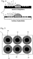
- the figure 4 schematically represents a set of grooves in the form of micro channels of triangular sections ( fig. 4 -high) or trapezoidal ( fig. 4 -low).
- the geometry of the various surface cavities and grooves constituting the micro-structured network of the support can be advantageously modified for the needs of the user.
- the use of a set of micro channels of constant section for the exhaust corridors also makes it possible to obtain a homogeneous filling of the exhaust zone and limits the filling errors linked to poor positioning of the user closure substrate.
- the figure 4 illustrates two schematic examples of exhaust networks made up of micro channels of triangular and trapezoidal sections thus defined.
- the thickness of the surface cavities is not necessarily homogeneous.
- the analysis zone may have a greater thickness than the exhaust corridors when it is desired to save the liquid sample to be analyzed while benefiting from a maximum of exhaust corridors for precise positioning of the fluid. 'sample. Conversely, deepening the exhaust corridors will allow more excess liquid to be stored to slow down the evaporation process.
- the figure 5 represents an example of a substrate according to the invention intended for a multisample analysis using surface cavities of circular lateral geometry.
- an exhaust network consisting of a plurality of circular grooves arranged concentrically around each analysis zone, each network being independent and separate from the other networks helps limit contamination between samples.
- analysis area can be organized as the related juxtaposition of several areas.
- closure substrate respectively the micro-structured substrate
- the closure substrate can be constituted by any system having a flat surface, respectively an upper surface, including analysis (CCD sensor, etc.) or control (microfluidic thermalization or perfusion chip).
- the system described by the invention can be used to position a biological sample in the form of a fine cavity before observation by optical microscopy.
- Another example of application consists in using the system of the invention for a system for biological detection by interaction with objects distributed on the surface of the substrate (DNA or protein chip) in which the invention makes it possible to close the chamber. reaction by ensuring a homogeneous reaction throughout the analysis zone.
- a third example of application is the systematic analysis of a chemical product using an automatic dispensing system coupled to a transmission analysis using a spectroscopy system of the fine cavity formed at the aid of the invention without leakage of the sample.
Landscapes
- Chemical & Material Sciences (AREA)
- Analytical Chemistry (AREA)
- Physics & Mathematics (AREA)
- Health & Medical Sciences (AREA)
- General Physics & Mathematics (AREA)
- General Health & Medical Sciences (AREA)
- Hematology (AREA)
- Clinical Laboratory Science (AREA)
- Chemical Kinetics & Catalysis (AREA)
- Optics & Photonics (AREA)
- Life Sciences & Earth Sciences (AREA)
- Immunology (AREA)
- Pathology (AREA)
- Biochemistry (AREA)
- Sampling And Sample Adjustment (AREA)
- Apparatus Associated With Microorganisms And Enzymes (AREA)
Claims (16)
- Optische Analyseanordnung für eine flüssige Probe, dadurch gekennzeichnet, dass sie ein mikrostrukturiertes Trägersubstrat (10) für eine flüssige Probe umfasst, welches eine Unterseite (11) und eine Oberseite (17) umfasst, wobei das Substrat einerseits mindestens einen Oberflächenhohlraum (12) mit einem Volumen V0, welcher an die Oberseite (17) mündet und eine Analysezone für die flüssige Probe bildet, und andererseits eine erste Rille (13) mit einem ersten Volumen V1, welche um jeden Oberflächenhohlraum (12) angeordnet ist und an seine Oberseite (17) mündet, sowie mindestens eine zweite Rille (14, 15, 16), die an seine Oberseite (17) mündet und um die erste Rille (13) herum angeordnet ist, wobei die Summe der Volumina der zweiten Rillen gleich V2 ist, wobei das Volumen V1+V2 grösser als oder gleich 0,05 V0 ist, vorzugsweise 0,1 V0, wobei die Tiefe der Rillen (13, 14, 15, 16) grösser als 10 Mikrometer und kleiner als 500 Mikrometer ist, vorzugsweise zwischen 20 Mikrometer und 500 Mikrometer, wobei die Rillen kontinuierlich und/oder nicht miteinander kommunizierend ausgebildet sind, wobei mindestens eine flüssige Probe (1), dessen Volumen grösser als die Summe der Volumina des Hohlraums (12) und der ersten Rille (13) ist, auf dem Substrat in mindestens einem Hohlraum (12) abgestellt ist, wobei das Substrat (10) von einer Lamelle (30) bedeckt ist, die alle Hohlräume (12) in dem Substrat (10) verschließt.
- Anordnung nach Anspruch 1, dadurch gekennzeichnet, dass das Volumen V1+V2 grösser als oder gleich 0,2 V0 ist, bevorzugter grösser als oder gleich 0,3 V0.
- Anordnung nach einem der Ansprüche 1 oder 2, dadurch gekennzeichnet, dass sie insgesamt n Nuten (13, 14, 15, 16) mit n>2 umfasst, wobei jede Rille der Reihe p, grösser als oder gleich 2 und kleiner als oder gleich n, um die Rille der Reihe (p-1) angeordnet ist, wobei das Gesamtvolumen V3 der (n-1) ersten Rillen (13, 14, 15) grösser als oder gleich 0,05 V0 ist.
- Anordnung nach einem der vorhergehenden Ansprüche, gekennzeichnet dadurch, dass sie n Rillen (13, 14, 15, 16) umfasst, wobei n kleiner als oder gleich 100 ist, vorzugsweise kleiner oder gleich 10.
- Anordnung nach einem der vorhergehenden Ansprüche, dadurch gekennzeichnet, dass der Querschnitt jeder Nute (13, 14, 15, 16) im wesentlichen identisch und/oder vorzugsweise konstant oder im wesentlichen konstant ist.
- Anordnung nach einem der vorhergehenden Ansprüche, gekennzeichnet dadurch, dass sie n konzentrische kreisförmige Rillen (13, 14, 15, 16) mit demselben Querschnitt umfasst, die vorzugsweise in gleichem Abstand voneinander angeordnet sind.
- Anordnung nach einem der vorhergehenden Ansprüche, dadurch gekennzeichnet, dass die Tiefe der Rillen zwischen etwa 10 Mikrometer und 500 Mikrometer liegt, vorzugsweise zwischen 20 Mikrometer und 500 Mikrometer.
- Anordnung nach einem der vorhergehenden Ansprüche, dadurch gekennzeichnet, dass der Abstand zwischen der Innenkontur einer Rille (14, 15, 16) und der Außenkontur der vorhergehenden, diese Rille umgebenden Rille (13, 14, 15) und/oder dem Hohlraum (12) zwischen etwa 1 Mikron und 1 mm ist, vorzugsweise gleich etwa 100 Mikron.
- Anordnung nach einem der vorhergehenden Ansprüche, dadurch gekennzeichnet, dass zumindest einige Bereiche der Oberseite (17) und/oder des Hohlraums (12) und/oder der Rillen so behandelt sind, dass sie in diesen Bereichen die Eigenschaften der Kapillarsperre verändern, die dem Oberflächenzustand des Materials des Substrats und/oder der Geometrie der Rillen und Oberflächen inhärent sind.
- Anordnung nach einem der vorhergehenden Ansprüche, dadurch gekennzeichnet, dass der Träger (10) mehrere Hohlräume (12) umfasst, wobei jeder von ihnen von mehreren Rillen (13, 14, 15, 16), zum Beispiel von den gleichen Anzahlen n von Rillen, umgeben ist.
- Anordnung nach einem der vorhergehenden Ansprüche, gekennzeichnet dadurch, dass sie mindestens sechs, vorzugsweise mindestens acht, Oberflächenhohlräume aufweist, wobei jeder Hohlraum einen Durchmesser von etwa 5 mm und eine Tiefe zwischen 20 Mikrometer und 500 Mikrometer aufweist, und um ungefähr 5 mm von einem anderen Hohlraum beabstandet ist, wobei jeder Hohlraum von einer Reihe von 5 bis 10 Rillen umgeben ist, die eine Tiefe von ungefähr 100 Mikrometern aufweisen und um ungefähr 100 Mikrometer voneinander beabstandet sind.
- Anordnung nach einem der vorhergehenden Ansprüche, dadurch gekennzeichnet, dass das Substrat (10) ein Mono- oder Mehrschichtmaterial umfasst, in dem mindestens eine der Rillen (13, 14, 15, 16) und/oder der Hohlraum (12) durch Ätzen oder thermischen, mechanischen und/oder chemischen Prozess gebildet werden.
- Anordnung nach einem der vorhergehenden Ansprüche, dadurch gekennzeichnet, dass das Volumen der ersten Nut (13) um mindestens dreimal, vorzugsweise mindestens fünfmal und bevorzugter mindestens zehnmal, kleiner als das Volumen V0 des Hohlraums (12) ist.
- Anordnung nach einem der vorhergehenden Ansprüche, gekennzeichnet dadurch, dass die Rillen in dem Substrat (10) Mikrokanäle mit einem dreieckigen oder trapezförmigen Querschnitt sind.
- Verwendung der Anordnung nach einem der Ansprüche 1 bis 14 zum Durchführen einer optischen Analyse für eine flüssige Probe.
- Verwendung nach Anspruch 15 zum Durchführen einer Analyse unter Verwendung der sogenannten PCR-Amplifikationstechnik.
Applications Claiming Priority (2)
| Application Number | Priority Date | Filing Date | Title |
|---|---|---|---|
| FR1501889A FR3040895B1 (fr) | 2015-09-11 | 2015-09-11 | Substrat de support d'echantillon liquide, ensemble comportant un tel substrat et son utilisation |
| PCT/EP2016/070805 WO2017042115A1 (fr) | 2015-09-11 | 2016-09-05 | Substrat de support d'échantillon liquide, ensemble comportant un tel substrat et son utilisation |
Publications (2)
| Publication Number | Publication Date |
|---|---|
| EP3347128A1 EP3347128A1 (de) | 2018-07-18 |
| EP3347128B1 true EP3347128B1 (de) | 2021-01-27 |
Family
ID=54937138
Family Applications (1)
| Application Number | Title | Priority Date | Filing Date |
|---|---|---|---|
| EP16760485.9A Active EP3347128B1 (de) | 2015-09-11 | 2016-09-05 | Anordnung mit trägersubstrat für flüssigkeitsprobe und verwendung davon |
Country Status (4)
| Country | Link |
|---|---|
| US (1) | US10471430B2 (de) |
| EP (1) | EP3347128B1 (de) |
| FR (1) | FR3040895B1 (de) |
| WO (1) | WO2017042115A1 (de) |
Families Citing this family (14)
| Publication number | Priority date | Publication date | Assignee | Title |
|---|---|---|---|---|
| BR112016011252B1 (pt) * | 2013-12-12 | 2020-11-24 | Mes Medical Electronic Systems Ltd | Dispositivo 0ptico, aparelho de teste, suporte de amostra e metodo para o teste |
| WO2017216270A1 (de) | 2016-06-15 | 2017-12-21 | Grabmayr Heinrich | Einzelmolekülnachweis bzw. -quantifizierung durch dna-nanotechnologie |
| WO2018039468A1 (en) * | 2016-08-26 | 2018-03-01 | Molecular Imprints, Inc. | Edge sealant confinement and halo reduction for optical devices |
| US10606054B2 (en) * | 2017-07-14 | 2020-03-31 | Sony Corporation | Super-resolution far-field scanning optical microscope |
| EP3700419A4 (de) * | 2017-10-26 | 2021-11-10 | Essenlix Corporation | Schnelltest von blutplättchen |
| US10606058B2 (en) * | 2018-01-11 | 2020-03-31 | Carol Lynn Espensen | Microscope slide for liquid cultures |
| WO2019202650A1 (ja) * | 2018-04-17 | 2019-10-24 | 株式会社 日立ハイテクノロジーズ | 顕微鏡用スライド、顕微鏡用スライドの製造方法、観察方法及び分析方法 |
| WO2019241398A1 (en) | 2018-06-12 | 2019-12-19 | Wendong Xing | Edge sealant application for optical devices |
| CN117310920A (zh) | 2018-07-23 | 2023-12-29 | 奇跃公司 | 用于边缘密封剂和层压坝的光学装置通气间隙 |
| WO2020081672A1 (en) | 2018-10-16 | 2020-04-23 | Magic Leap, Inc. | Methods and apparatuses for casting polymer products |
| TWI672764B (zh) * | 2018-11-07 | 2019-09-21 | 國立成功大學 | 晶片封裝裝置及其對位壓合方法 |
| US10775099B1 (en) * | 2019-08-27 | 2020-09-15 | Whirlpool Corporation | Refrigerator with a shelf |
| CN111781160B (zh) * | 2020-08-04 | 2024-11-05 | 重庆邮电大学 | 一种用于黏稠液体样品太赫兹光谱检测的样品池装置 |
| WO2022192683A1 (en) * | 2021-03-11 | 2022-09-15 | Virginia Tech Intellectual Properties, Inc. | Methods and apparatus for evaporation based liquid transport |
Family Cites Families (14)
| Publication number | Priority date | Publication date | Assignee | Title |
|---|---|---|---|---|
| US2041290A (en) | 1935-01-12 | 1936-05-19 | Jackson William Peter | Agglutinating test plate |
| US2302830A (en) | 1940-10-30 | 1942-11-24 | Sol A Axelrad | Microscope test slide |
| US4387972A (en) * | 1981-02-26 | 1983-06-14 | Immuno Concepts, Inc. | Microscope slide with confirming wells |
| US4882245A (en) | 1985-10-28 | 1989-11-21 | International Business Machines Corporation | Photoresist composition and printed circuit boards and packages made therewith |
| US5948685A (en) | 1998-02-10 | 1999-09-07 | Angros; Lee | Analytic plate with containment border and method of use |
| US6764652B2 (en) * | 2001-01-24 | 2004-07-20 | The Regents Of The University Of Michigan | Micromachined device for receiving and retaining at least one liquid droplet, method of making the device and method of using the device |
| CA2455344A1 (en) * | 2001-04-20 | 2002-10-31 | Jenara Enterprises Ltd. | Apparatus and control for variable exhaust brake |
| JP3675735B2 (ja) | 2001-05-28 | 2005-07-27 | アロカ株式会社 | 液展開用部材及びそれを用いたサンプル処理装置 |
| AU2003202120A1 (en) * | 2002-01-17 | 2003-07-30 | University College Cork-National University Of Ireland, Cork | An assay device and method for chemical or biological screening |
| US20030194709A1 (en) * | 2002-04-10 | 2003-10-16 | Xing Yang | Hydrophobic zone device |
| WO2006052492A1 (en) | 2004-11-08 | 2006-05-18 | Ventana Medical Systems, Inc. | Preglued coverglass with roughened glue surface |
| US20120004140A1 (en) * | 2008-02-01 | 2012-01-05 | Complete Genomics, Inc. | Flow cells for biochemical analysis |
| TWI388829B (zh) * | 2009-12-29 | 2013-03-11 | Nat Applied Res Laboratoires | 聚合酶連鎖反應之方法、聚合酶連鎖反應之液珠裝置及其陣列式液珠裝置 |
| CA2825615C (en) | 2011-03-03 | 2020-02-25 | F. Hoffmann-La Roche Ag | Hanging droplet plate |
-
2015
- 2015-09-11 FR FR1501889A patent/FR3040895B1/fr active Active
-
2016
- 2016-09-05 EP EP16760485.9A patent/EP3347128B1/de active Active
- 2016-09-05 US US15/759,218 patent/US10471430B2/en active Active
- 2016-09-05 WO PCT/EP2016/070805 patent/WO2017042115A1/fr not_active Ceased
Non-Patent Citations (1)
| Title |
|---|
| None * |
Also Published As
| Publication number | Publication date |
|---|---|
| EP3347128A1 (de) | 2018-07-18 |
| US20180250670A1 (en) | 2018-09-06 |
| US10471430B2 (en) | 2019-11-12 |
| FR3040895B1 (fr) | 2020-01-10 |
| FR3040895A1 (fr) | 2017-03-17 |
| WO2017042115A1 (fr) | 2017-03-16 |
Similar Documents
| Publication | Publication Date | Title |
|---|---|---|
| EP3347128A1 (de) | Trägersubstrat für flüssigkeitsprobe, anordnung mit solch einem substrat und verwendung davon | |
| EP2609993B1 (de) | Nano- und mikro-fluidische Vorrichtung für die Trennung und Konzentration von in einem Fluid vorhandenen Partikeln | |
| WO2010004014A1 (fr) | Procede et dispositif de manipulation et d'observation de gouttes de liquide | |
| EP2903738B1 (de) | Mikrofluidisches verfahren zur behandlung und analyse einer lösung mit einem biologischem material und entsprechende mikrofluidische schaltung | |
| EP2769214B1 (de) | Molekulare erfassungsvorrichtung | |
| EP1781409B1 (de) | Vorrichtung zur handhabung von tropfen zur biochemischen analyse, verfahren zur herstellung einer derartigen vorrichtung und system zur mikrofluidischen analyse | |
| CN106104271B (zh) | 具有锥形珠陷获腔的微流体芯片及其制造 | |
| WO2012143908A1 (fr) | Système microfluidique pour contrôler la concentration de molécules de stimulation d'une cible. | |
| EP3085444B1 (de) | Mikrofluidvorrichtung zur fliesskontrolle eines fluids | |
| FR2887305A1 (fr) | Dispositif de pompage par electromouillage et application aux mesures d'activite electrique | |
| EP3059300A1 (de) | Vorrichtung zur manipulation von biologischen zellen mithilfe einer schwingenden halterung | |
| FR2861610A1 (fr) | Dispositif de travail comprenant une zone localisee de capture d'une goutte d'un liquide d'interet | |
| EP1682273B1 (de) | Begrenzte bearbeitungszonen umfassende bearbeitungsvorrichtung, on-chip-labor und mikrosystem | |
| FR3033407A1 (fr) | Dispositif de prelevement d'un echantillon liquide par capillarite. | |
| EP1677914B1 (de) | Verfahren zur verteilung von tropfen einer betreffenden flüssigkeit auf einer fläche | |
| FR3058995A1 (fr) | Procede et systeme de commande d'un dispositif microfluidique | |
| FR2890975A1 (fr) | Plaque de tests a puits. | |
| WO2006131679A2 (fr) | Dispositif planaire avec adressage de puits automatise par electromouillage dynamique | |
| FR2883860A1 (fr) | Procede de fabrication de micro-canaux enterres et micro-dispositif comprenant de tels micro-canaux. | |
| FR2806009A1 (fr) | Procede de mise en oeuvre d'une carte d'analyse | |
| WO2021234310A1 (fr) | Puce microfluidique tridimensionnelle, procede de fabrication d'une telle puce et utilisation pour la separation de particules dans des solutions colloïdales | |
| FR2862239A1 (fr) | Dispositif de reception d'un echantillon de fluide, et ses applications | |
| WO2003033147A1 (fr) | Dispositif micro-fluidique pour la manipulation d'un liquide non magnetique. | |
| WO2020128182A1 (fr) | Procede de remplissage selectif, par un liquide de remplissage, d'un groupe de cavites parmi une pluralite de cavites | |
| EP2260336B1 (de) | Verfahren zur herstellung von mikron- oder submikronkavitäten |
Legal Events
| Date | Code | Title | Description |
|---|---|---|---|
| STAA | Information on the status of an ep patent application or granted ep patent |
Free format text: STATUS: THE INTERNATIONAL PUBLICATION HAS BEEN MADE |
|
| PUAI | Public reference made under article 153(3) epc to a published international application that has entered the european phase |
Free format text: ORIGINAL CODE: 0009012 |
|
| STAA | Information on the status of an ep patent application or granted ep patent |
Free format text: STATUS: REQUEST FOR EXAMINATION WAS MADE |
|
| 17P | Request for examination filed |
Effective date: 20180307 |
|
| AK | Designated contracting states |
Kind code of ref document: A1 Designated state(s): AL AT BE BG CH CY CZ DE DK EE ES FI FR GB GR HR HU IE IS IT LI LT LU LV MC MK MT NL NO PL PT RO RS SE SI SK SM TR |
|
| AX | Request for extension of the european patent |
Extension state: BA ME |
|
| DAV | Request for validation of the european patent (deleted) | ||
| DAX | Request for extension of the european patent (deleted) | ||
| STAA | Information on the status of an ep patent application or granted ep patent |
Free format text: STATUS: EXAMINATION IS IN PROGRESS |
|
| 17Q | First examination report despatched |
Effective date: 20191029 |
|
| GRAP | Despatch of communication of intention to grant a patent |
Free format text: ORIGINAL CODE: EPIDOSNIGR1 |
|
| STAA | Information on the status of an ep patent application or granted ep patent |
Free format text: STATUS: GRANT OF PATENT IS INTENDED |
|
| INTG | Intention to grant announced |
Effective date: 20200917 |
|
| GRAS | Grant fee paid |
Free format text: ORIGINAL CODE: EPIDOSNIGR3 |
|
| GRAA | (expected) grant |
Free format text: ORIGINAL CODE: 0009210 |
|
| STAA | Information on the status of an ep patent application or granted ep patent |
Free format text: STATUS: THE PATENT HAS BEEN GRANTED |
|
| AK | Designated contracting states |
Kind code of ref document: B1 Designated state(s): AL AT BE BG CH CY CZ DE DK EE ES FI FR GB GR HR HU IE IS IT LI LT LU LV MC MK MT NL NO PL PT RO RS SE SI SK SM TR |
|
| REG | Reference to a national code |
Ref country code: GB Ref legal event code: FG4D Free format text: NOT ENGLISH |
|
| REG | Reference to a national code |
Ref country code: CH Ref legal event code: EP |
|
| REG | Reference to a national code |
Ref country code: AT Ref legal event code: REF Ref document number: 1357852 Country of ref document: AT Kind code of ref document: T Effective date: 20210215 |
|
| REG | Reference to a national code |
Ref country code: IE Ref legal event code: FG4D Free format text: LANGUAGE OF EP DOCUMENT: FRENCH |
|
| REG | Reference to a national code |
Ref country code: DE Ref legal event code: R096 Ref document number: 602016052089 Country of ref document: DE |
|
| REG | Reference to a national code |
Ref country code: NL Ref legal event code: MP Effective date: 20210127 |
|
| REG | Reference to a national code |
Ref country code: LT Ref legal event code: MG9D |
|
| REG | Reference to a national code |
Ref country code: AT Ref legal event code: MK05 Ref document number: 1357852 Country of ref document: AT Kind code of ref document: T Effective date: 20210127 |
|
| PG25 | Lapsed in a contracting state [announced via postgrant information from national office to epo] |
Ref country code: FI Free format text: LAPSE BECAUSE OF FAILURE TO SUBMIT A TRANSLATION OF THE DESCRIPTION OR TO PAY THE FEE WITHIN THE PRESCRIBED TIME-LIMIT Effective date: 20210127 Ref country code: HR Free format text: LAPSE BECAUSE OF FAILURE TO SUBMIT A TRANSLATION OF THE DESCRIPTION OR TO PAY THE FEE WITHIN THE PRESCRIBED TIME-LIMIT Effective date: 20210127 Ref country code: GR Free format text: LAPSE BECAUSE OF FAILURE TO SUBMIT A TRANSLATION OF THE DESCRIPTION OR TO PAY THE FEE WITHIN THE PRESCRIBED TIME-LIMIT Effective date: 20210428 Ref country code: PT Free format text: LAPSE BECAUSE OF FAILURE TO SUBMIT A TRANSLATION OF THE DESCRIPTION OR TO PAY THE FEE WITHIN THE PRESCRIBED TIME-LIMIT Effective date: 20210527 Ref country code: NO Free format text: LAPSE BECAUSE OF FAILURE TO SUBMIT A TRANSLATION OF THE DESCRIPTION OR TO PAY THE FEE WITHIN THE PRESCRIBED TIME-LIMIT Effective date: 20210427 Ref country code: LT Free format text: LAPSE BECAUSE OF FAILURE TO SUBMIT A TRANSLATION OF THE DESCRIPTION OR TO PAY THE FEE WITHIN THE PRESCRIBED TIME-LIMIT Effective date: 20210127 Ref country code: BG Free format text: LAPSE BECAUSE OF FAILURE TO SUBMIT A TRANSLATION OF THE DESCRIPTION OR TO PAY THE FEE WITHIN THE PRESCRIBED TIME-LIMIT Effective date: 20210427 |
|
| PG25 | Lapsed in a contracting state [announced via postgrant information from national office to epo] |
Ref country code: SE Free format text: LAPSE BECAUSE OF FAILURE TO SUBMIT A TRANSLATION OF THE DESCRIPTION OR TO PAY THE FEE WITHIN THE PRESCRIBED TIME-LIMIT Effective date: 20210127 Ref country code: LV Free format text: LAPSE BECAUSE OF FAILURE TO SUBMIT A TRANSLATION OF THE DESCRIPTION OR TO PAY THE FEE WITHIN THE PRESCRIBED TIME-LIMIT Effective date: 20210127 Ref country code: RS Free format text: LAPSE BECAUSE OF FAILURE TO SUBMIT A TRANSLATION OF THE DESCRIPTION OR TO PAY THE FEE WITHIN THE PRESCRIBED TIME-LIMIT Effective date: 20210127 Ref country code: PL Free format text: LAPSE BECAUSE OF FAILURE TO SUBMIT A TRANSLATION OF THE DESCRIPTION OR TO PAY THE FEE WITHIN THE PRESCRIBED TIME-LIMIT Effective date: 20210127 Ref country code: AT Free format text: LAPSE BECAUSE OF FAILURE TO SUBMIT A TRANSLATION OF THE DESCRIPTION OR TO PAY THE FEE WITHIN THE PRESCRIBED TIME-LIMIT Effective date: 20210127 |
|
| PG25 | Lapsed in a contracting state [announced via postgrant information from national office to epo] |
Ref country code: IS Free format text: LAPSE BECAUSE OF FAILURE TO SUBMIT A TRANSLATION OF THE DESCRIPTION OR TO PAY THE FEE WITHIN THE PRESCRIBED TIME-LIMIT Effective date: 20210527 |
|
| REG | Reference to a national code |
Ref country code: DE Ref legal event code: R097 Ref document number: 602016052089 Country of ref document: DE |
|
| PG25 | Lapsed in a contracting state [announced via postgrant information from national office to epo] |
Ref country code: CZ Free format text: LAPSE BECAUSE OF FAILURE TO SUBMIT A TRANSLATION OF THE DESCRIPTION OR TO PAY THE FEE WITHIN THE PRESCRIBED TIME-LIMIT Effective date: 20210127 Ref country code: EE Free format text: LAPSE BECAUSE OF FAILURE TO SUBMIT A TRANSLATION OF THE DESCRIPTION OR TO PAY THE FEE WITHIN THE PRESCRIBED TIME-LIMIT Effective date: 20210127 Ref country code: SM Free format text: LAPSE BECAUSE OF FAILURE TO SUBMIT A TRANSLATION OF THE DESCRIPTION OR TO PAY THE FEE WITHIN THE PRESCRIBED TIME-LIMIT Effective date: 20210127 |
|
| PG25 | Lapsed in a contracting state [announced via postgrant information from national office to epo] |
Ref country code: DK Free format text: LAPSE BECAUSE OF FAILURE TO SUBMIT A TRANSLATION OF THE DESCRIPTION OR TO PAY THE FEE WITHIN THE PRESCRIBED TIME-LIMIT Effective date: 20210127 Ref country code: RO Free format text: LAPSE BECAUSE OF FAILURE TO SUBMIT A TRANSLATION OF THE DESCRIPTION OR TO PAY THE FEE WITHIN THE PRESCRIBED TIME-LIMIT Effective date: 20210127 Ref country code: SK Free format text: LAPSE BECAUSE OF FAILURE TO SUBMIT A TRANSLATION OF THE DESCRIPTION OR TO PAY THE FEE WITHIN THE PRESCRIBED TIME-LIMIT Effective date: 20210127 |
|
| PLBE | No opposition filed within time limit |
Free format text: ORIGINAL CODE: 0009261 |
|
| STAA | Information on the status of an ep patent application or granted ep patent |
Free format text: STATUS: NO OPPOSITION FILED WITHIN TIME LIMIT |
|
| 26N | No opposition filed |
Effective date: 20211028 |
|
| PG25 | Lapsed in a contracting state [announced via postgrant information from national office to epo] |
Ref country code: ES Free format text: LAPSE BECAUSE OF FAILURE TO SUBMIT A TRANSLATION OF THE DESCRIPTION OR TO PAY THE FEE WITHIN THE PRESCRIBED TIME-LIMIT Effective date: 20210127 Ref country code: AL Free format text: LAPSE BECAUSE OF FAILURE TO SUBMIT A TRANSLATION OF THE DESCRIPTION OR TO PAY THE FEE WITHIN THE PRESCRIBED TIME-LIMIT Effective date: 20210127 |
|
| PG25 | Lapsed in a contracting state [announced via postgrant information from national office to epo] |
Ref country code: SI Free format text: LAPSE BECAUSE OF FAILURE TO SUBMIT A TRANSLATION OF THE DESCRIPTION OR TO PAY THE FEE WITHIN THE PRESCRIBED TIME-LIMIT Effective date: 20210127 |
|
| PG25 | Lapsed in a contracting state [announced via postgrant information from national office to epo] |
Ref country code: IT Free format text: LAPSE BECAUSE OF FAILURE TO SUBMIT A TRANSLATION OF THE DESCRIPTION OR TO PAY THE FEE WITHIN THE PRESCRIBED TIME-LIMIT Effective date: 20210127 |
|
| REG | Reference to a national code |
Ref country code: CH Ref legal event code: PL |
|
| REG | Reference to a national code |
Ref country code: BE Ref legal event code: MM Effective date: 20210930 |
|
| PG25 | Lapsed in a contracting state [announced via postgrant information from national office to epo] |
Ref country code: IS Free format text: LAPSE BECAUSE OF FAILURE TO SUBMIT A TRANSLATION OF THE DESCRIPTION OR TO PAY THE FEE WITHIN THE PRESCRIBED TIME-LIMIT Effective date: 20210527 Ref country code: MC Free format text: LAPSE BECAUSE OF FAILURE TO SUBMIT A TRANSLATION OF THE DESCRIPTION OR TO PAY THE FEE WITHIN THE PRESCRIBED TIME-LIMIT Effective date: 20210127 |
|
| PG25 | Lapsed in a contracting state [announced via postgrant information from national office to epo] |
Ref country code: LU Free format text: LAPSE BECAUSE OF NON-PAYMENT OF DUE FEES Effective date: 20210905 Ref country code: IE Free format text: LAPSE BECAUSE OF NON-PAYMENT OF DUE FEES Effective date: 20210905 Ref country code: BE Free format text: LAPSE BECAUSE OF NON-PAYMENT OF DUE FEES Effective date: 20210930 |
|
| PG25 | Lapsed in a contracting state [announced via postgrant information from national office to epo] |
Ref country code: LI Free format text: LAPSE BECAUSE OF NON-PAYMENT OF DUE FEES Effective date: 20210930 Ref country code: CH Free format text: LAPSE BECAUSE OF NON-PAYMENT OF DUE FEES Effective date: 20210930 |
|
| PG25 | Lapsed in a contracting state [announced via postgrant information from national office to epo] |
Ref country code: HU Free format text: LAPSE BECAUSE OF FAILURE TO SUBMIT A TRANSLATION OF THE DESCRIPTION OR TO PAY THE FEE WITHIN THE PRESCRIBED TIME-LIMIT; INVALID AB INITIO Effective date: 20160905 |
|
| PG25 | Lapsed in a contracting state [announced via postgrant information from national office to epo] |
Ref country code: NL Free format text: LAPSE BECAUSE OF NON-PAYMENT OF DUE FEES Effective date: 20210127 Ref country code: CY Free format text: LAPSE BECAUSE OF FAILURE TO SUBMIT A TRANSLATION OF THE DESCRIPTION OR TO PAY THE FEE WITHIN THE PRESCRIBED TIME-LIMIT Effective date: 20210127 |
|
| PG25 | Lapsed in a contracting state [announced via postgrant information from national office to epo] |
Ref country code: MK Free format text: LAPSE BECAUSE OF FAILURE TO SUBMIT A TRANSLATION OF THE DESCRIPTION OR TO PAY THE FEE WITHIN THE PRESCRIBED TIME-LIMIT Effective date: 20210127 |
|
| REG | Reference to a national code |
Ref country code: DE Ref legal event code: R081 Ref document number: 602016052089 Country of ref document: DE Owner name: MICROFLUIDICS INNOVATION CENTER, FR Free format text: FORMER OWNER: ELVESYS, PARIS, FR |
|
| PG25 | Lapsed in a contracting state [announced via postgrant information from national office to epo] |
Ref country code: MT Free format text: LAPSE BECAUSE OF FAILURE TO SUBMIT A TRANSLATION OF THE DESCRIPTION OR TO PAY THE FEE WITHIN THE PRESCRIBED TIME-LIMIT Effective date: 20210127 |
|
| REG | Reference to a national code |
Ref country code: GB Ref legal event code: 732E Free format text: REGISTERED BETWEEN 20240912 AND 20240918 |
|
| PGFP | Annual fee paid to national office [announced via postgrant information from national office to epo] |
Ref country code: DE Payment date: 20250916 Year of fee payment: 10 |
|
| PGFP | Annual fee paid to national office [announced via postgrant information from national office to epo] |
Ref country code: GB Payment date: 20250919 Year of fee payment: 10 |
|
| PGFP | Annual fee paid to national office [announced via postgrant information from national office to epo] |
Ref country code: FR Payment date: 20250929 Year of fee payment: 10 |
|
| PG25 | Lapsed in a contracting state [announced via postgrant information from national office to epo] |
Ref country code: TR Free format text: LAPSE BECAUSE OF FAILURE TO SUBMIT A TRANSLATION OF THE DESCRIPTION OR TO PAY THE FEE WITHIN THE PRESCRIBED TIME-LIMIT Effective date: 20210127 |