EP3347312B1 - Procédés et systèmes de déshydratation de particules solides dans un mélange liquide contaminé - Google Patents
Procédés et systèmes de déshydratation de particules solides dans un mélange liquide contaminé Download PDFInfo
- Publication number
- EP3347312B1 EP3347312B1 EP16843735.8A EP16843735A EP3347312B1 EP 3347312 B1 EP3347312 B1 EP 3347312B1 EP 16843735 A EP16843735 A EP 16843735A EP 3347312 B1 EP3347312 B1 EP 3347312B1
- Authority
- EP
- European Patent Office
- Prior art keywords
- assembly
- liquid
- filter
- shockwave
- filters
- Prior art date
- Legal status (The legal status is an assumption and is not a legal conclusion. Google has not performed a legal analysis and makes no representation as to the accuracy of the status listed.)
- Active
Links
Images



Classifications
-
- B—PERFORMING OPERATIONS; TRANSPORTING
- B01—PHYSICAL OR CHEMICAL PROCESSES OR APPARATUS IN GENERAL
- B01D—SEPARATION
- B01D29/00—Filters with filtering elements stationary during filtration, e.g. pressure or suction filters, not covered by groups B01D24/00 - B01D27/00; Filtering elements therefor
- B01D29/62—Regenerating the filter material in the filter
- B01D29/70—Regenerating the filter material in the filter by forces created by movement of the filter element
- B01D29/72—Regenerating the filter material in the filter by forces created by movement of the filter element involving vibrations
-
- B—PERFORMING OPERATIONS; TRANSPORTING
- B01—PHYSICAL OR CHEMICAL PROCESSES OR APPARATUS IN GENERAL
- B01D—SEPARATION
- B01D29/00—Filters with filtering elements stationary during filtration, e.g. pressure or suction filters, not covered by groups B01D24/00 - B01D27/00; Filtering elements therefor
- B01D29/11—Filters with filtering elements stationary during filtration, e.g. pressure or suction filters, not covered by groups B01D24/00 - B01D27/00; Filtering elements therefor with bag, cage, hose, tube, sleeve or like filtering elements
- B01D29/114—Filters with filtering elements stationary during filtration, e.g. pressure or suction filters, not covered by groups B01D24/00 - B01D27/00; Filtering elements therefor with bag, cage, hose, tube, sleeve or like filtering elements arranged for inward flow filtration
-
- B—PERFORMING OPERATIONS; TRANSPORTING
- B01—PHYSICAL OR CHEMICAL PROCESSES OR APPARATUS IN GENERAL
- B01D—SEPARATION
- B01D29/00—Filters with filtering elements stationary during filtration, e.g. pressure or suction filters, not covered by groups B01D24/00 - B01D27/00; Filtering elements therefor
- B01D29/50—Filters with filtering elements stationary during filtration, e.g. pressure or suction filters, not covered by groups B01D24/00 - B01D27/00; Filtering elements therefor with multiple filtering elements, characterised by their mutual disposition
- B01D29/52—Filters with filtering elements stationary during filtration, e.g. pressure or suction filters, not covered by groups B01D24/00 - B01D27/00; Filtering elements therefor with multiple filtering elements, characterised by their mutual disposition in parallel connection
-
- B—PERFORMING OPERATIONS; TRANSPORTING
- B01—PHYSICAL OR CHEMICAL PROCESSES OR APPARATUS IN GENERAL
- B01D—SEPARATION
- B01D29/00—Filters with filtering elements stationary during filtration, e.g. pressure or suction filters, not covered by groups B01D24/00 - B01D27/00; Filtering elements therefor
- B01D29/60—Filters with filtering elements stationary during filtration, e.g. pressure or suction filters, not covered by groups B01D24/00 - B01D27/00; Filtering elements therefor integrally combined with devices for controlling the filtration
- B01D29/603—Filters with filtering elements stationary during filtration, e.g. pressure or suction filters, not covered by groups B01D24/00 - B01D27/00; Filtering elements therefor integrally combined with devices for controlling the filtration by flow measuring
-
- B—PERFORMING OPERATIONS; TRANSPORTING
- B01—PHYSICAL OR CHEMICAL PROCESSES OR APPARATUS IN GENERAL
- B01D—SEPARATION
- B01D29/00—Filters with filtering elements stationary during filtration, e.g. pressure or suction filters, not covered by groups B01D24/00 - B01D27/00; Filtering elements therefor
- B01D29/62—Regenerating the filter material in the filter
- B01D29/66—Regenerating the filter material in the filter by flushing, e.g. counter-current air-bumps
-
- B—PERFORMING OPERATIONS; TRANSPORTING
- B01—PHYSICAL OR CHEMICAL PROCESSES OR APPARATUS IN GENERAL
- B01D—SEPARATION
- B01D29/00—Filters with filtering elements stationary during filtration, e.g. pressure or suction filters, not covered by groups B01D24/00 - B01D27/00; Filtering elements therefor
- B01D29/96—Filters with filtering elements stationary during filtration, e.g. pressure or suction filters, not covered by groups B01D24/00 - B01D27/00; Filtering elements therefor in which the filtering elements are moved between filtering operations; Particular measures for removing or replacing the filtering elements; Transport systems for filters
-
- B—PERFORMING OPERATIONS; TRANSPORTING
- B01—PHYSICAL OR CHEMICAL PROCESSES OR APPARATUS IN GENERAL
- B01D—SEPARATION
- B01D41/00—Regeneration of the filtering material or filter elements outside the filter for liquid or gaseous fluids
- B01D41/04—Regeneration of the filtering material or filter elements outside the filter for liquid or gaseous fluids of rigid self-supporting filtering material
-
- B—PERFORMING OPERATIONS; TRANSPORTING
- B08—CLEANING
- B08B—CLEANING IN GENERAL; PREVENTION OF FOULING IN GENERAL
- B08B7/00—Cleaning by methods not provided for in a single other subclass or a single group in this subclass
- B08B7/02—Cleaning by methods not provided for in a single other subclass or a single group in this subclass by distortion, beating, or vibration of the surface to be cleaned
-
- C—CHEMISTRY; METALLURGY
- C02—TREATMENT OF WATER, WASTE WATER, SEWAGE, OR SLUDGE
- C02F—TREATMENT OF WATER, WASTE WATER, SEWAGE, OR SLUDGE
- C02F1/00—Treatment of water, waste water, or sewage
- C02F1/001—Processes for the treatment of water whereby the filtration technique is of importance
-
- C—CHEMISTRY; METALLURGY
- C02—TREATMENT OF WATER, WASTE WATER, SEWAGE, OR SLUDGE
- C02F—TREATMENT OF WATER, WASTE WATER, SEWAGE, OR SLUDGE
- C02F2209/00—Controlling or monitoring parameters in water treatment
- C02F2209/10—Solids, e.g. total solids [TS], total suspended solids [TSS] or volatile solids [VS]
-
- C—CHEMISTRY; METALLURGY
- C02—TREATMENT OF WATER, WASTE WATER, SEWAGE, OR SLUDGE
- C02F—TREATMENT OF WATER, WASTE WATER, SEWAGE, OR SLUDGE
- C02F2209/00—Controlling or monitoring parameters in water treatment
- C02F2209/40—Liquid flow rate
-
- C—CHEMISTRY; METALLURGY
- C02—TREATMENT OF WATER, WASTE WATER, SEWAGE, OR SLUDGE
- C02F—TREATMENT OF WATER, WASTE WATER, SEWAGE, OR SLUDGE
- C02F2303/00—Specific treatment goals
- C02F2303/16—Regeneration of sorbents, filters
Definitions
- the present disclosure relates generally to methods, system, and apparatuses for treating and decontaminating contaminated liquid mixtures, and more particularly, for dewatering solids and/or solid particles contained and/or found in contaminated liquid mixtures or sludges.
- the present disclosure relates, in some embodiments, to methods and systems for dewatering solid particles in a contaminated liquid mixture.
- filter clogging may occur through agglomeration, accumulation, and/or flocculation of solid particles. Filter clogging may lead to a loss in dewatering process efficiency and may lead to an increase in system maintenance, energy costs, labor costs, filter disposal costs, maintenance downtime, and filter media replacement costs. Further, filter clogging may reduce the life of pump seals, valves, and process equipment.
- US5213687 discloses an apparatus for filtering slurries of minerals or other fine particles.
- the apparatus includes a ceramic filter plate and a fluid flow device for drawing a partial vacuum across said filter plate and to supply a pulsed liquid to the filtrate side of said filter plate.
- the apparatus also includes an oscillating device that facilitates removal of cake which accumulates on the filter plate when sued simultaneously with or successively with said pulsed liquid.
- US2004262209 discloses a filtration apparatus in which filtration is carried out by use of a gelatinous filter apparatus.
- a bubble supplying mechanism is provided for removing a sedimentary layer comprising removables that is formed on a surface of a filtration film, and a filtration characteristics restoring mechanism is provided for restoring the filter film clogged by the removables by causing a back-flow of filtered water accumulated in a cistern.
- a lower part inside a raw water tank is tapered and a recovery tank is provided for recovering removables via a valve.
- the present disclosure relates, in some embodiments to methods, systems, and apparatuses for treating, dewatering, and/or decontaminating contaminated liquid mixtures.
- methods, systems, apparatuses, and controllers may be used in treating and/or decontaminating liquid mixtures, and more specifically, for use in the dewatering of solids and/or solid particles contained in contaminated liquid mixtures.
- the method may be directed to a chemical-free process.
- Methods may comprise, for example, receiving a liquid mixture (e.g., a liquid mixture including solid particles).
- a method may comprise contacting a filter with a liquid mixture.
- a method may comprise agglomerating (or flocculating), at a filter, solid particles in a liquid mixture.
- Agglomerating (or flocculating) may include potentiating passage of a liquid in a liquid mixture through a filter to form a cake or wet cake (e.g., greater than 15%).
- Agglomerating may include potentiating accumulation of solid particles in the liquid mixture to collect and agglomerate (or flocculate) at the filter.
- a method may comprise applying a shockwave to a filter. An applied shockwave may be operable to remove agglomerated (or flocculated) solid particles from a filter.
- a method may comprise potentiating passage of a liquid in a liquid mixture through a filter and potentiating accumulation of solid particles in the liquid mixture to collect and (optionally) agglomerate (or flocculate) at the filter by applying a negative pressure. Agglomeration of solid particles before accumulating at the filter may not be required and a method may be automated to continuously perform dewatering of solids and/or solid particles.
- a filter may be connected to an outlet section.
- a pressure differential may be applied by introducing a negative pressure between a filter and an outlet section.
- a pressure differential may be applied by introducing a liquid suction between a filter and the outlet section.
- a liquid mixture may be housed in a container and a pressure differential may be selectively applied by introducing positive pressure into a container.
- a pressure differential may be selectively applied when a flow rate of liquid passing through a filter exceeds a minimum threshold value.
- a pressure differential may be selectively applied based on, for example, thickness, consistency, or other aspects of a layer of solid particles agglomerated at a filter.
- a pressure differential may be applied when agglomerated solid particles may not be removed from a filter.
- a pressure differential may be applied on a periodic basis.
- agglomerated solid particles are removed from a filter on a periodic basis.
- a filter may be selected based on, for example, size of the solid particles in the liquid mixture.
- a method for dewatering solid particles in a liquid mixture may comprises receiving a liquid mixture (e.g., a liquid mixture including solid particles).
- a method may comprise suspending a filter in the liquid mixture.
- a method may comprise agglomerating (or flocculating), at a filter, solid particles in a liquid mixture.
- Agglomerating (or flocculating) may include applying a pressure differential to potentiate passage of liquid in the liquid mixture through a filter.
- Agglomerating (or flocculating) may further include applying a pressure differential to potentiate collection, deposition, agglomeration, and/or flocculation of solid particles in a liquid mixture at a filter.
- a method may comprise removing agglomerated (or flocculated) solid particles from a filter.
- a shockwave may be selectively applied when a flow rate of liquid passing through a filter may be below a minimum threshold value.
- a shockwave may be selectively applied based on, for example, thickness, consistency, or other aspects of solid particles agglomerated at a filter.
- a shockwave may be applied when liquid in the liquid mixture may be not passing through the filter.
- a method may comprise removing a filter from a liquid mixture, wherein a shockwave may be applied when the filter may be removed from the liquid mixture.
- a filter may be connected to an outlet section; and wherein agglomerating includes potentiating passage of liquid passing through a filter to pass to an outlet section.
- a liquid passage through the filter may be potentiated by applying a liquid suction.
- a liquid passage through a filter may be potentiated by applying a pressure differential.
- a pressure differential may be selectively applied by introducing a negative pressure between a filter and an outlet section.
- a liquid mixture may be housed in a container and a pressure differential may be selectively applied by introducing positive pressure into a container.
- a pressure differential may be selectively applied when a flow rate of liquid passing through a filter exceeds a minimum threshold value.
- a pressure differential may be selectively applied based on, for example, thickness, consistency, or other aspects of solid particles agglomerated at a filter.
- a liquid passage through a filter may be potentiated on a periodic basis.
- a shockwave may be applied on a periodic basis.
- a filter may be selected base on, for example, size of solid particles in a liquid mixture, according to some embodiments.
- a system may comprise a filter assembly configured in a dead end manner.
- a filter assembly may include a filter.
- a filter may include an outwardly facing exterior surface and an inwardly facing opposing interior surface.
- a filter may also include a plurality of pores.
- a plurality of pores may be operable to allow liquid to pass through a filter.
- a plurality of pores may also be operable to prevent one or more solid particles from passing through a filter.
- a system may comprise a liquid removal assembly.
- a liquid removal assembly may be configurable to create an inwardly-directed suction at the pores of a filter.
- a system may comprise a shockwave assembly.
- a shockwave assembly may be in communication with a filter.
- a shockwave assembly may be configurable to apply a shockwave to a filter.
- a filter may be suspended in a liquid mixture having solid particles
- a liquid removal assembly may be configurable create the inwardly-directed suction to potentiate passage of liquid in the liquid mixture through the pores of the filter and potentiate accumulation of solid particles in the liquid mixture to collect and agglomerate at an exterior surface of the filter.
- a shockwave assembly may be configurable to remove agglomerated solid particles from an exterior surface of the filter.
- a system may comprise a liquid flow meter operable to measure a flow rate of liquid passing through the filter assembly.
- a shockwave assembly may be configurable to apply a shockwave to a filter when a liquid flow rate may be below a minimum threshold value.
- a system may comprise a liquid outlet section connected to a filter assembly, a liquid outlet section operable to discharge a liquid passing through a filter assembly.
- a liquid removal assembly may comprise a liquid suction introduced between a filter assembly and a liquid outlet section, in some embodiments.
- a system may comprise, in some embodiments, a container for housing the liquid mixture, wherein an inwardly-directed suction may be a pressure differential created by introducing positive pressure into a container.
- a liquid removal assembly may be configurable to create an inwardly-directed suction when a liquid flow rate exceeds a minimum threshold value.
- a liquid removal assembly may create an inwardly-directed suction when a shockwave assembly does not apply a shockwave to the filter.
- a filter may be a ceramic membrane.
- a system comprises a controller, the controller operable to configure a liquid removal assembly to create an inwardly-directed suction and configure a shockwave assembly to apply a shockwave.
- a controller is in communication with a liquid flow meter, the liquid flow meter operable to measure a flow of liquid through the filter assembly.
- a controller may configure a liquid removal assembly to create an inwardly-directed suction when a measured liquid flow through a filter assembly exceeds a minimum threshold value.
- a controller is operable to configure a shockwave assembly to apply a shockwave when a measured liquid flows through a filter assembly may be below a minimum threshold value.
- a controller may configure a shockwave assembly to apply a shockwave when a liquid removal assembly may be configured to not create an inwardly-directed suction.
- a system may further comprise an anchor assembly, wherein a controller may be operable to configure the anchor assembly to secure a filter of a filter assembly at a first location, the first location being a location inside a container housing a liquid mixture; and wherein the controller may be operable to configure a liquid removal assembly to create an inwardly-directed suction when the anchor assembly may be configured to secure the filter at the first location.
- a controller may be operable to configure an anchor assembly to move a filter of the filter assembly between a first location and a second location, the second location being a location outside of a container.
- a controller may be operable to configure a shockwave assembly to apply a shockwave when an anchor assembly may be configured to secure a filter at the second location.
- a method for dewatering liquid mixture containing solid particles may comprise, according to some embodiments, configuring a filter assembly in a dead end manner.
- a filter assembly may include an exposed filter and a body attached to the filter.
- a filter may have a plurality of pores.
- a method may comprise providing a liquid outlet section.
- a liquid outlet section may be operable to receive and discharge liquid.
- a method may comprise connecting a liquid removal assembly between the body of a filter assembly and a liquid outlet section.
- a method may further comprise configuring a liquid removal assembly.
- a liquid removal assembly may be configured to selectively apply an inwardly-directed suction at pores of a filter.
- a method may further comprise configuring a shockwave assembly.
- a shockwave assembly may be configured to selectively apply a shockwave to a filter.
- a system comprises, in embodiments, a flow meter to measure a liquid flow through a filter assembly.
- a system may comprise providing a controller, wherein the controller may be operable to configure a liquid removal assembly to selectively apply an inwardly-directed suction, according to some embodiments.
- a controller may be operable to communicate with a flow meter, and a controller may be configure a liquid removal assembly to selectively apply an inwardly-directed suction when a measured liquid flow exceeds a minimum threshold value.
- a controller is operable to configure a shockwave assembly to selectively apply a shockwave.
- a controller is operable to configure a shockwave assembly to selectively apply a shockwave when a measured liquid flow may be below a minimum threshold value.
- FIGURES 1A-F illustrate example embodiments of a system 100 for use in, among other things, dewatering solids and/or solid particles contained in a contaminated liquid mixture.
- the system e.g., element 100
- the system includes one or more filter assemblies (e.g., element 110), one or more liquid removal assemblies (e.g., element 120), and one or more shockwave assemblies (e.g., element 130).
- the system 100 may perform the dewatering of solids and/or solid particles using a chemical-free process.
- Filter assembly (e.g. , element 110).
- System 100 comprises one or more filter assemblies 110.
- One or more filter assemblies 110 may comprise one or more filters 112, such as a ceramic membrane 112, or the like. As illustrated in Figures 1A-F , one or more filter assemblies 110 are configured in a "dead-end" manner and for use with or in a liquid mixture housed (or received or contained) in a container 102, or the like.
- One or more filter assemblies 110 may be configured in an outside-in arrangement such that one or more filters 112 is/are directly exposed to liquid mixture 104 when one or more filters 112 is/are submerged (or immersed or introduced or suspended) in liquid mixture 104.
- one or more filters 112 may be submerged in such a way that one or more filters 112 is/are suspended in the liquid mixture, resting at a bottom surface of container 102, positioned near a top portion of container 102, and/or selectively or dynamically moved based on, among other things, a quantity (such as depth) of liquid mixture 104, size or shape of container 102, etc.
- one or more filters 112 of one or more filter assemblies 110 may include an outwardly facing exterior surface 112a and an inwardly facing interior surface 112b opposite to the exterior surface.
- the inwardly facing interior surface 112b may be considered as facing outlet section 140 in example embodiments.
- One or more filters 112 may include a plurality of pores 112c, or the like. Pores 112c may be operable to allow liquid to pass through filter 112 (such as from an area 112a' near outwardly facing exterior surface 112a to an area 112b' near inwardly facing interior surface 112b). Pores 112c of one or more filters 112 may be further operable to prevent one or more solid particles 106 from passing through filter 112. In example embodiments, such solid particles 106 may collect and agglomerate (or flocculate) to form larger-sized solid particles (or macro particles) at outwardly facing exterior surface 112a of one or more filters 112 when liquid in liquid mixture 104 passes through filter 112. Such encouraging will be further discussed in sections "Liquid removal assembly (e.g., element 120)" and “Methods for dewatering solids and/or solid particles (e.g., method 300),” and herein.
- Liquid removal assembly e.g., element 120
- Method 300
- Pores 112c may be of any shape, size, dimension, quantity, and/or separation spacing in example embodiments.
- the sizes (and/or shapes and/or quantities and/or spacing) of pores 112c i.e., filter 112
- the sizes (and/or shapes and/or quantities and/or spacing) of pores 112c may be selected based on, among other things, a known or expected size (which can be a minimum, average, mean, etc. value), dimension, quantity, density, and/or shape of solid particles 106 contained in liquid mixture 104.
- diameters of pores 112c may be about 0.05 to 1 microns.
- Filter 112 may be formed in any shape and/or quantity.
- one or more filters 112 may be a substantially flat rectangular shaped filter 112, as illustrated in Figures 1A , 1C , and 1E .
- One or more filters 112 may also be a substantially cylindrical, as illustrated in Figure 1B .
- One or more filters 112 may also be a substantially circular shaped, as illustrated in Figure 1E .
- One or more filters 112 may also be formed in other 2-dimensional and/or 3-dimensional shapes, including, but not limited to, square or cubical shapes, oval shapes, hexagonal shapes, combination of shapes, other geometrical shapes, irregular shapes, etc.
- Two or more filters 112 may be provided for filter assembly 110, as illustrated in Figure 1B .
- Filter 112 may have any shape, dimension (e.g., porosity), and/or size desired. Selection of the shape, dimension, and/or size of filter 112 may be based on one or more considerations, including, but not limited to, the amount (or depth, volume, concentration, etc.) of liquid mixture 104 being treated, the amount of solid particles 106 in liquid mixture 104, and/or size, shape, and/or dimension of container 102 used to receive and house liquid mixture 104.
- Example shapes of container 102 may include, but are not limited to, cylindrical shaped containers 102, cubical shaped containers 102, rectangular shaped containers 102, spherical shaped containers 102, etc.
- Example dimensions of filter 112 may include, but are not limited to, a length of about 14.3 cm, a width of about 24 to 48 cm, and a depth of about 6 mm.
- solid particles 106 in liquid mixture 104 may agglomerate (or flocculate) to form larger sized solid particles (or macro particles) at inwardly facing interior surface of container 102.
- Solid particles 106 that have agglomerated to form larger sized particles on an inwardly facing interior surface of container 102 may be removed by various means.
- Means for removing may comprise dumping, pouring, scraping, lifting, extracting, prying, sloughing, and combinations thereof.
- Filter 112 may be formed of any desired material.
- Example material compositions include, but are not limited to, ceramic (SiC, Alumina), titania, and polymeric.
- ceramic may be preferred for its ability to handle shockwaves provided by a shockwave assembly (e.g., shockwave assembly 130).
- One or more filter assemblies 110 may be in communication with (i.e., connected or attached, directly or indirectly, to) one or more outlet sections 140 via one or more pipes, tubes, channels, or the like 114 (hereinafter "pipe"), as illustrated in Figures 1A-F .
- Pipes e.g., pipes 114
- Size may be selected based on one or more of considerations, including, but not limited to, an amount of liquid mixture 104 received in container 102, desired processing time, desired liquid flow to the outlet section 140, characteristics of filter 112, etc.
- Example diameters of the pipes 114 may be between about 0.25 to 1 cm.
- one or more filter assemblies 110 may be connected, directly or indirectly, to one or more outlet sections 140 via one or more liquid removal assemblies 120, as illustrated in Figures 1A-D .
- Liquid removal assembly 120 will be further discussed in the sections "Liquid removal assembly ( e.g., element 120)" and “Methods for dewatering solids and/or solid particles ( e.g., method 300)," and herein.
- one or more filter assemblies 110 may be connected, directly or indirectly, to one or more outlet sections 140 via one or more valves 162, as illustrated in Figures 1B-D .
- the valves 162 may be any quantity or type of valve known in the art including, but not limited to, a control valve, gate valve, ball valve, etc.
- one or more filter assemblies 110 may be connected, directly or indirectly, to one or more outlet sections 140 via one or more liquid flow meters 150, as illustrated in Figures 1A-E .
- One or more filter assemblies 110 may be configurable to communicate with (i.e., connect or attach, directly or indirectly, to) one or more shockwave assemblies 130 via one or more pipes, tubes, channels, or the like 114 and/or 116, as illustrated in Figures 1A-F .
- one or more filters 112 may be connected, directly or indirectly, to one or more shockwave assemblies 130, and such connection may be via one or more valves 164.
- the valves 164 may be any quantity or type of valve known in the art including, but not limited to, a control valve, gate valve, ball valve, etc.
- Liquid removal assembly (e.g. , element 120).
- System 100 comprises a liquid removal assembly 120.
- Liquid removal assembly 120 is configured to create, among other things, suction. Such suction may be created in one or more of a plurality of ways, such as by creating a pressure reduction (or negative pressure or suction force) between or in an area between filter assembly 110 and the outlet section 140.
- Liquid removal assembly 120 may be configurable to create an inwardly-directed suction (or vacuum or suction force) at, in, and/or around the pores 112c of one or more filters 112, as well as in areas 112a' and 112b' and pipes 114 and 116, in example embodiments.
- an inwardly-directed suction at the pores 112c may be a suction force directed towards outlet section 140, and more specifically, from area 112a' towards area 112b' (and towards outlet section 140), as illustrated in Figure 1F .
- liquid removal assembly 120 may be configurable to potentiate passage of liquid in liquid mixture 104 through one or more filters 112 (i.e., via pores 112c). Liquid removal assembly 120 may also be configurable to potentiate collection, deposition, agglomeration, and/or flocculation of solid particles 106 in liquid mixture 104 at one or more filters 112 (i.e., at outwardly facing exterior surface 112a of one or more filters 112).
- liquid removal assembly 120 may be configurable to agglomerate (or flocculate), at one or more filters 112, solid particles in liquid mixture 104, and such agglomerating (or flocculating) may be performed by, among other things, encouraging or potentiating passage of liquid in liquid mixture 104 through one or more filters 112, applying the differential pressure, and/or applying the inwardly-directed suction.
- liquid removal assembly 120 may be a pump, vacuum, compressor, or the like.
- a liquid removal assembly may be configured to modify the vacuum strength. Modifying vacuum strength may allow, in some embodiments, the thickness, consistency, or another aspect of the cake to be pre-selected and/or adjusted during operation. In some embodiments, a higher vacuum strength may produce a thicker cake. A lower vacuum strength, according to some embodiments, may produce a thinner cake. According to some embodiments, a higher vacuum strength may produce a dryer cake. A higher vacuum strength may also produce a more compact cake, according to some solid particles 106 agglomerated (or flocculated) at one or more filters 112 reaches a certain consistency. Considerations of solid particles 106 agglomerated (or flocculated) at one or more filters 112 may be performed in any desired manner. For example, assessment may embodiments. A lower vacuum strength, in some embodiments, may produce a wetter cake. A lower vacuum strength, may produce a more voluminous cake, according to some embodiments.
- Liquid removal assembly 120 may also create a pressure differential between the interior of container 102 and an area between one or more filter assemblies 110 and the outlet section 140 by configuring liquid removal assembly 120 to introduce a positive pressure into container 102, as illustrated in Figure 1E .
- container 102 may be substantially sealed, such as in an airtight manner (or hermetically sealed), and the positive pressure may be operable to potentiate passage of liquid in liquid mixture 104 through one or more filters 112 (i.e, via pores 112c) and solid particles 106 in liquid mixture 104 to collect and agglomerate (or flocculate) at one or more filters 112 (i.e., at outwardly facing exterior surface 112a of one or more filters 112).
- liquid removal assembly 120 may create and/or maintain a pressure differential, inwardly-directed suction, potentiate passage of liquid through one or more filters 112, and/or potentiate accumulation of solid particles 106 to collect and agglomerate (or flocculate) at one or more filters 112 based on, among other things, a consideration of a measured flow rate of liquid passing through one or more filters 112, one or more filter assemblies 110, liquid removal section 120, and/or outlet section 140.
- the measured flow rate may be a real-time measure, average or mean value measure, minimum (or maximum) value measure, etc., in example embodiments.
- liquid removal assembly 120 may continue to perform the pressure differential, inwardly-directed suction, encouraging or potentiating passage of liquid, and agglomerating (or flocculating) of solid particles 106 when one or more flow meters 150 measures a real-time or minimum liquid flow rate to at least exceed a minimum threshold value.
- the minimum threshold value may be about 0 gallons per minute.
- liquid removal assembly 120 may create and/or maintain a pressure differential, inwardly-directed suction, potentiate passage of liquid through one or more filters 112, and potentiate accumulation of solid particles 106 to collect and agglomerate (or flocculate) at one or more filters 112 based on, among other things, other metrics including pressure, pressure drop, weight, mass, flow, time, etc.
- liquid removal assembly 120 continues to perform the pressure differential, inwardly-directed suction, and/or encouraging or potentiating passage of liquid through one or more filters 112, solid particles 106 in liquid mixture 104 may continue to collect and agglomerate (or flocculate) at one or more filters 112.
- the flow rate of liquid passing through one or more filters 112, one or more filter assemblies 110, liquid removal section 120, and/or outlet section 140 may reduce accordingly.
- liquid removal assembly 120 may be configurable to continue performing the pressure differential, inwardly-directed suction, encouraging or potentiating passage of liquid, and agglomerating (or flocculating) of solid particles 106, and may stop doing so when the liquid flow rate reaches or drops below the minimum threshold value.
- liquid removal assembly 120 may be configurable to selectively or dynamically adjust (e.g., increase) the pressure differential, inwardly-directed suction, and/or encouraging or potentiating passage of liquid as the flow rate of liquid reduces (or is reduced) based on the measured liquid flow rate so as to attempt to boost or maintain the liquid flow rate at a desired value or above a minimum threshold value.
- liquid removal assembly 120 may perform the pressure differential, inwardly-directed suction, encouraging or potentiating passage of liquid through one or more filters 112, and/or potentiating accumulation of solid particles 106 to collect and agglomerate (or flocculate) at one or more filters 112 based on, among other things, a consideration of solid particles 106 agglomerated (or flocculated) at one or more filters 112 (i.e., outwardly facing exterior surface 112a of one or more filters 112).
- the consideration of solid particles 106 agglomerated (or flocculated) at one or more filters 112 may be a real-time consideration, average or mean consideration, minimum (or maximum) consideration, etc., in example embodiments.
- liquid removal assembly 120 may continue to perform the pressure differential, inwardly-directed suction, encouraging or potentiating passage of liquid, and/or agglomerating (or flocculating) of solid particles 106 until a thickness (average, mean, maximum, etc.) of solid particles 106 agglomerated (or flocculated) at one or more filters 112 reaches a certain maximum threshold value.
- the maximum threshold value may be about 0.5 to 10 mm.
- liquid removal assembly 120 may perform the pressure differential, inwardly-directed suction, encouraging or potentiating passage of liquid, and/or agglomerating (or flocculating) of solid particles 106 until a layer of include visual inspection, measured liquid flow rate, pressure, pressure differential, weight, mass, flow, time, etc.
- Liquid removal assembly 120 may perform the pressure differential, inwardly-directed suction, encouraging or potentiating passage of liquid through one or more filters 112, and/or potentiating accumulation of solid particles 106 to collect and agglomerate (or flocculate) at one or more filters 112 when shockwave assembly 130 is configured to not remove the agglomerated (or flocculated) solid particles 106 from one or more filters 112.
- liquid removal assembly 120 performs said pressure differential, inwardly-directed suction, encouraging or potentiating passage of liquid through one or more filters 112, and/or potentiating accumulation of solid particles 106 to collect and agglomerate (or flocculate) at one or more filters 112 on a periodic, intermittent, scheduled, or random basis, or based on visual inspections.
- Shockwave assembly (e.g. , element 130).
- System 100 comprises a shockwave assembly 130.
- Shockwave assembly 130 is configured to apply, among other things, a shockwave (or dynamic shock), or the like, and such shockwave is applied to one or more filter assemblies 110.
- Shockwave assembly 130 may create (and/or introduce, apply, etc.) the shockwave in one or more of a plurality of ways known in the art.
- the shockwave may be applied to a vertically-oriented or substantially vertically-oriented filter 112 and/or filter assembly 110.
- a vertical orientation may facilitate or permit dewatered solids to separate from and/or fall off a filter (e.g., filter 112).
- shockwave assembly 130 may be configurable to apply the shockwave to one or more filters 112 so as to cause the collected and agglomerated (or flocculated) solid particles 106 to be removed from one or more filters 112.
- shockwave assembly 130 may be operable to receive an applied pressure to generate the shockwave and control a duration of the applied shockwave.
- Shockwave assembly 130 may be operable to control a magnitude of the shockwave applied to one or more filters 112 and/or one or more filter assemblies 110 in example embodiments.
- shockwave assembly 130 may be configurable to apply a low energy shockwave, a high energy shockwave, a variation of or between low and high energy shockwaves, etc.
- a shockwave assembly may be configurable to modify frequency of shockwave pulses.
- a shockwave assembly may be configured to modify a pressure applied by a shockwave pulse. Modifying shockwave frequency and/or pressure may allow, in some embodiments, the thickness, consistency, or another aspect of the cake to be pre-selected and/or adjusted during operation.
- a higher frequency of shockwave pulses may produce a thinner cake.
- a lower frequency shockwave pulses may produce a thicker cake, according to some embodiments.
- a lower pressure shockwave may produce a thicker cake.
- a high pressure shockwave may produce a thinner cake, in some embodiments.
- a greater frequency of shockwave pulses and/or a greater shockwave pulse pressure may produce a thinner cake.
- a lower frequency of shockwave pulses and/or a lower shockwave pulse pressure may produce a thicker cake.
- a shockwave pulse pressure may be selected to avoid overly stressing or damaging a plate filter (e.g., a flat plate filter).
- shockwave assembly 130 may be configurable to apply a shockwave to one or more filters 112 based on, among other things, a consideration of a measured flow rate of liquid passing through one or more filters 112, one or more filter assemblies 110, liquid removal section 120, and/or outlet section 140.
- the measured flow rate may be a real-time measure, average or mean value measure, minimum (or maximum) value measure, etc., in example embodiments.
- shockwave assembly 130 may apply the shockwave to one or more filters 112 when one or more flow meters 150 measures a real-time or minimum liquid flow rate to be below a minimum threshold value.
- the minimum threshold value may be about 0 gallons per minute.
- liquid removal assembly 120 continues to perform the pressure differential, inwardly-directed suction, and/or encouraging or potentiating passage of liquid through one or more filters 112
- solid particles 106 in liquid mixture 104 may continue to collect and agglomerate (or flocculate) at one or more filters 112 and the flow rate of liquid passing through one or more filters 112, one or more filter assemblies 110, liquid removal section 120, and/or outlet section 140 may reduce accordingly.
- shockwave assembly 130 may be configurable to selectively or dynamically apply the shockwave to one or more filters 112 to remove solid particles 106 collected and agglomerated (or flocculated) at one or more filters 112 and enable liquid removal assembly 120 to continue performing the pressure differential, inwardly-directed suction, and/or encouraging of liquid to pass through one or more filters 112.
- shockwave assembly 130 may be configurable to selectively or dynamically apply the shockwave to one or more filters 112 based on, among other things, a consideration of solid particles 106 agglomerated (or flocculated) at one or more filters 112 (i.e., outwardly facing exterior surface 112a of one or more filters 112).
- the consideration of solid particles 106 agglomerated (or flocculated) at one or more filters 112 may be a real-time consideration, average or mean consideration, minimum (or maximum) consideration, etc., in example embodiments.
- shockwave assembly 130 may selectively apply the shockwave to one or more filters 112 when a thickness (average, mean, maximum, etc.) of solid particles 106 agglomerated (or flocculated) at one or more filters 112 reaches a certain maximum threshold value.
- the maximum threshold value may be about 0.5 to 10 mm.
- shockwave assembly 130 may selectively apply the shockwave to one or more filters 112 when a layer of solid particles 106 agglomerated (or flocculated) at one or more filters 112 reaches a certain consistency.
- Considerations of solid particles 106 agglomerated (or flocculated) at one or more filters 112 may be performed in one or more of a plurality of other ways, including, but not limited to, visual inspection, measured liquid flow rate, other metrics including pressure, pressure drop, weight, mass, flow, time, etc.
- Shockwave assembly 130 may also be configured to selectively or dynamically apply a shockwave to one or more filters 112 when liquid removal assembly 120 is configured to not perform the pressure differential, inwardly-directed suction, encouraging or potentiating passage of liquid through one or more filters 112, and/or potentiating accumulation of solid particles 106 to collect and agglomerate (or flocculate) at one or more filters 112.
- shockwave assembly 130 may also be configured to selectively or dynamically apply the shockwave to one or more filters 112 when one or more filters 112 is/are not suspended in liquid mixture 104, such as when one or more filters 112 is/are removed from liquid mixture 104 and/or container 102, liquid mixture 104 in container 202 is substantially removed, etc.
- shockwave assembly 130 may be configured to selectively or dynamically apply the shockwave to one or more filters 112 on a periodic, intermittent, scheduled, or random basis, or based on visual inspections.
- Controller e.g., element 160.
- Controller 160 may be any device operable to communicate with one or more elements of system 100, and may include a , including a computing device, communication device, virtual machine, computer, node, instance, host, or machine in a networked computing environment.
- Controller 160 may comprise logic stored in non-transitory computer readable medium which, when executed by controller 160 and/or a processor of or associated with controller 160, is operable to perform one or more operations, configuring actions, and/or communications with one or more elements of system 200, as described in the present disclosure. Controller 160 is operable to communicate with liquid removal assembly 120, shockwave assembly 130, and flow meter 150. Controller 160 is operable to configure liquid removal assembly 120 and shockwave assembly 130. Controller 160 may be operable to communicate with and/or configure one or more of filter assembly 110, outlet section 140, valve 162, valve 164, valve 166, and/or anchor assembly 200.
- controller 160 may be operable to control the passing of liquid through one or more filters 112, one or more filter assemblies 110, one or more pipes 114 and 116, one or more liquid removal assemblies 120, one or more flow meters 150, and/or one or more outlet sections 140, as well as control the collecting and agglomerating (or flocculating) of solid particles 106 on one or more filters 112.
- controller 160 is operable to configure liquid removal assembly 120 to perform the pressure differential, inwardly-directed suction, encouraging or potentiating passage of liquid through one or more filters 112, and/or potentiating accumulation of solid particles 106 to collect and agglomerate (or flocculate) at one or more filters 112, as described above and in the present disclosure.
- controller 160 communicates with flow meter 150, to obtain a measured flow rate of liquid passing through one or more filters 112, and liquid removal section 120, and controller 160 may communicate with, among other things, one or more filter assemblies 110 and/or outlet section 140, and controller 160 is operable to configure the liquid removal section 120 to create the inwardly-directed suction and may start, stop, or adjust the performance of liquid removal assembly 120 accordingly.
- Controller 130 also communicates with shockwave assembly 130 and may determine whether or not a shockwave is being applied to one or more filters 112, and controller 160 is operable to configure the shockwave assembly to apply a shockwave to the one or more filters 112 and may start, stop, or adjust the performance of shockwave assembly 130 accordingly.
- Controller 130 may also communicate with one or more valves 162, 164, and/or 166 to ensure shockwave assembly 130 does not apply a shockwave when liquid removal assembly 120 is in operation (if needed). Controller 130 may also communicate with anchor assembly 200 to determine whether one or more filters 112 is/are in the first location, second location, or other location, or whether one or more filters 112 is/are being selectively or dynamically moved and/or secured at other locations within container 102, and controller 160 may start, stop, or adjust the performance of liquid removal assembly 120 accordingly.
- Controller 160 may be operable to control, according to some embodiments, the removal of solid particles 106 collected and agglomerated (or flocculated) on one or more filters 112.
- controller 160 is operable to configure shockwave assembly 130 to apply a shockwave to one or more filters 112, as described above and in the present disclosure.
- controller 160 communicates with flow meter 150, to obtain a measured flow rate of liquid passing through one or more filters 112, and may communicate with, among other things, one or more filter assemblies 110, liquid removal section 120, and/or outlet section 140, and controller 160 is operable to apply a shockwave to the one or more filters 112 and may start, stop, or adjust (such as increase or decrease the magnitude of the applied shockwave) the performance of shockwave assembly 130 accordingly.
- Controller 130 also communicates with liquid removal assembly 120 and may determine whether or not liquid removal assembly 120 is performing the pressure differential, inwardly-directed suction, encouraging or potentiating passage of liquid through one or more filters 112, and/or potentiating accumulation of solid particles 106 to collect and agglomerate (or flocculate) at one or more filters 112, and controller 160 may start, stop, or adjust the performance of liquid removal assembly 120 accordingly.
- Controller 130 may also communicate with one or more valves 162, 164, and/or 166 to ensure liquid removal assembly 120 is not performing the pressure differential, inwardly-directed suction, and/or encouraging of liquid to pass through one or more filters 112 and solid particles 106 to collect and agglomerate (or flocculate) at one or more filters 112 when shockwave assembly 130 is in operation (if needed). Controller 130 may also communicate with anchor assembly 200 to determine whether one or more filters 112 is/are in the first location, second location, or other location, or whether one or more filters 112 is/are being selectively or dynamically moved and/or secured at other locations within container 102, and controller 160 may start, stop, or adjust the performance of shockwave assembly 130 accordingly.
- controller 160 may be operable to control the moving and/or securing of one or more filters 112 at or between the first location, the second location, and/or other locations, and/or the selective or dynamic moving and/or securing of one or more filters 112 in other locations within container 102, as described above and in the present disclosure.
- controller 160 may be operable to configure anchor assembly 200 to secure one or more filters 112 at a first location.
- Controller 160 may also be operable to configure anchor assembly 200 to secure one or more filters 112 at a second location.
- Controller 160 may also be operable to configure anchor assembly 200 to move one or more filters 112 between a first location and a second location.
- Controller 160 may also be operable to configure anchor assembly 200 to secure one or more filters 112 at other locations.
- controller 160 may be operable to configure anchor assembly 200 to selectively or dynamically move and/or secure one or more filters 112 in other locations within container 102.
- Controller 160 may be operable to control, according to some embodiments, liquid removal assembly 120 to continue to perform the pressure differential, inwardly-directed suction, encouraging or potentiating passage of liquid through one or more filters 112, and/or potentiating accumulation of solid particles 106 to collect and agglomerate (or flocculate) at one or more filters 112 when one or more filters 112 and/or one or more filter assemblies 110 is/are at a location (such as the second location) outside of container 102 and/or other location in respect of which one or more filters 112 is/are not suspended in liquid mixture 104.
- liquid from the pores 112c of one or more filters 112 may be further removed, the formed cake or wet cake (i.e., agglomerated or flocculated solid particles at one or more filters 112) may be further dried, and the shockwave applied by shockwave assembly 130 may be provided through air (or more air rather than through liquid or more liquid).
- the controller 160 may be operable, according to some embodiments, to reduce the distance that the shockwave applied by the shockwave assembly 130 needs to travel from the shockwave assembly 130 to one or more filters 112.
- the controller 160 may be operable, according to some embodiments, to cause the shockwave assembly 130 to be closer to one or more filters 112 and/or cause a pipe 114 and/or 116 to be shortened between the shockwave assembly 130 and one or more filters 112.
- Anchor assembly (e.g. , element 200).
- FIGURES 2A and 2B illustrate an example embodiment of a system 220 comprising an anchor assembly 200.
- anchor assembly 200 may be operable to secure to one or more filters 212, one or more filter assemblies 210, container 202, and/or a secure base.
- anchor assembly 200 may be configurable to secure one or more filters 212 to be fixedly positioned at a first location (or position), as illustrated in Figure 2A .
- the first location may be a location inside container 202 and/or a location in respect of which one or more filters 212 is/are suspended in liquid mixture 204 when container 202 receives and houses liquid mixture 204.
- Anchor assembly 200 may be further configurable to secure one or more filters 212 to be fixedly positioned at a second location (or position), as illustrated in Figure 2B .
- the second location may be a location outside of container 202 and/or a location in respect of which one or more filters 212 is/are not suspended in liquid mixture 204 when container 202 receives and houses liquid mixture 204.
- Anchor assembly 200 may be further configurable to move one or more filters 212 between the first location and the second location.
- Anchor assembly 200 may be further configurable to selectively or dynamically move and/or secure one or more filters 212 to be fixedly positioned at other locations, such as locations within container 202.
- Such selective or dynamic moving and/or securing may be based on, among other things, a quantity (such as depth) of liquid mixture 204 in container 202, shape or size of container 202, measured liquid flow rate, amount of solid particles 206 collected and agglomerated (or flocculated) on one or more filters 212, location on one or more filters 212 where solid particles 206 have collected and agglomerated (or flocculated), etc.
- liquid removal assembly 220 may be configured to perform the pressure differential, inwardly-directed suction, encouraging or potentiating passage of liquid through one or more filters 212, and/or encouraging or potentiating accumulation of solid particles 206 to collect and agglomerate (or flocculate) at one or more filters 212 when anchor assembly 200 secures one or more filters 12 at the first location.
- shockwave assembly (e.g, 120) may be configured to selectively apply the shockwave to one or more filters (e.g., 112, 212) when anchor assembly 200 secures one or more filters (e.g., 112, 212) at the first location, such as in situations wherein the agglomerated (or flocculated) solid particles (e.g., 106) are desired to be provided at the bottom of container (e.g., 102, 202), as illustrated in Figures 1A-E and Figures 2A-B .
- filters e.g., 112, 212
- Shockwave assembly 120 may also be selectively configured to not apply the shockwave to one or more filters 212 when anchor assembly 200 secures one or more filters 212 at the first location, such as in situations wherein the agglomerated (or flocculated) solid particles 206 are desired to be removed and provided in a separate container 210 or location, as illustrated in Figure 2B .
- liquid removal assembly 220 may be configured to briefly perform the pressure differential, inwardly-directed suction, encouraging or potentiating passage of liquid through filter 212, and/or potentiating accumulation of solid particles 206 to collect and agglomerate (or flocculate) at one or more filters 212 when anchor assembly 200 secures one or more filters 212 at the second location, such as in situations wherein a dampness of or water surrounding the agglomerated (or flocculated) solid particles 206 collected at one or more filters 212 are desired to be reduced before shockwave assembly 230 applies the shockwave to one or more filters 212.
- Liquid removal assembly 220 may also be selectively configured to not perform the pressure differential, inwardly-directed suction, encouraging or potentiating passage of liquid through filter 212, and/or potentiating accumulation of solid particles 206 to collect and agglomerate (or flocculate) at one or more filters 212 when anchor assembly 200 secures one or more filters 212 at the second location, such as in situations wherein the agglomerated (or flocculated) solid particles 206 collected at one or more filters 212 are desired to be removed and provided in a separate container 210 or location, as illustrated in Figure 2B .
- Shockwave assembly 220 may also be selectively configured to apply the shockwave to filter 212 when anchor assembly 200 secures one or more filters 212 at the second location.
- liquid removal assembly 220 may be selectively configured to perform the pressure differential, inwardly-directed suction, encouraging or potentiating passage of liquid through one or more filters 212, and/or potentiating accumulation of solid particles 206 to collect and agglomerate (or flocculate) at one or more filters 212 when one or more filters 212 is/are selectively or dynamically moved within container 202, as described above and in the present disclosure.
- shockwave assembly 220 may be selectively configured to apply the shockwave to one or more filters 212 when one or more filters 212 is/are selectively or dynamically moved within container 202, such as in situations wherein the agglomerated (or flocculated) solid particles 206 are desired to be provided at the bottom of container 202, as illustrated in Figures 1A-E .
- Shockwave assembly 220 may also be selectively configured to not apply the shockwave to one or more filters 212 when one or more filters 212 is/are selectively or dynamically moved within container 202, such as in situations wherein the agglomerated (or flocculated) solid particles 206 are desired to be removed and provided in a separate container 210 or location, as illustrated in Figure 2B .
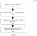
- Method for dewatering solids and/or solid particles e.g ., method 300.
- method 300 for dewatering solids and/or solid particles may comprise receiving liquid mixture 104 (e.g., action 302), as described above and in the present disclosure.
- Liquid mixture 104 may be received in a container 102, or the like.
- Liquid mixture 104 may include solid particles 106.
- the method 300 may be directed to a chemical-free process.
- Method 300 may further comprise suspending one or more filters 112 of one or more filter assemblies 110 in liquid mixture 104 (e.g., action 304), as described above and in the present disclosure.
- One or more filters 112 may be suspended and secured in place at a first location in one or more of a plurality of ways. For example, one or more filters 112 may be secured to a portion of container 102 and/or cover for container 102. One or more filters 112 may also be secured by anchoring assembly 200. One or more filters 112 may also be moved and/or secured to other locations within container 102, and such may also be performed by the anchoring assembly 200 in example embodiments.
- Method 300 may further comprise agglomerating (or flocculating), at one or more filters 112, solid particles 106 in liquid mixture 104 (e.g., action 306).
- agglomerating (or flocculating) e.g., action 306 may be performed by liquid removal assembly 120, as described above and in the present disclosure.
- Agglomerating (or flocculating) may include encouraging or potentiating passage of liquid in liquid mixture 104 through filter 112 and potentiating accumulation of solid particles 106 in liquid mixture 104 to collect and agglomerate (or flocculate) at one or more filters 112 (i.e., at outwardly facing exterior surface 112a of one or more filters 112).
- Agglomerating may include applying a pressure differential to potentiate passage of liquid in liquid mixture 104 through one or more filters 112 and potentiating accumulation of solid particles 106 in liquid mixture 104 to collect and agglomerate (or flocculate) at one or more filters 112 (i.e., at outwardly facing exterior surface 112a of one or more filters 112).
- Agglomerating (or flocculating) may include applying an inwardly-directed suction (or vacuum or suction force) at, in, and/or around the pores 112c of one or more filters 112, as well as in areas 112a' and 112b' and pipes 114 and 116.
- the pressure differential may be applied by liquid removal assembly 120, as described above and in the present disclosure.
- the pressure differential may be applied by introducing a negative pressure between or at an area between one or more filters 112 and the outlet section 140.
- the pressure differential may also be applied by introducing a liquid suction between one or more filters 112 and external liquid outlet section 140.
- the pressure differential may also be applied by introducing a positive pressure into container 102, as illustrated in Figure 1E .
- the pressure differential may be selectively applied based on a consideration of liquid flow through one or more filters 112, one or more filter assemblies 110, liquid removal section 120, and/or outlet section 140. For example, the pressure differential may be selectively applied when the flow rate of liquid passing through one or more filters 112, one or more filter assemblies 110, liquid removal section 120, and/or outlet section 140 exceeds a minimum threshold value.
- the pressure differential may be selectively applied based on a consideration of solid particles 106 agglomerated (or flocculated) at one or more filters 112.
- the consideration may include a consideration of the thickness of solid particles 106 agglomerated (or flocculated) at one or more filters 112.
- the consideration may include a consideration of the consistency of the layer of solid particles 106 agglomerated (or flocculated) at one or more filters 112.
- the pressure differential may also be applied on a periodic, intermittent, scheduled, or random basis, or based on visual inspections.
- Method 300 may further comprise removing the agglomerated (or flocculated) solid particles 106 from one or more filters 112 (e.g., action 308), as described above and in the present disclosure.
- the removing of the agglomerated (or flocculated) solid particles 106 from one or more filters 112 may be performed by applying a shockwave to one or more filters 112.
- Such applying of the shockwave to one or more filters 112 may be performed by shockwave assembly 130.
- the shockwave may be selectively applied based on a consideration of liquid flow through one or more filters 112, one or more filter assemblies 110, liquid removal section 120, and/or outlet section 140.
- the shockwave may be selectively applied when the flow rate of liquid passing through one or more filters 112, one or more filter assemblies 110, liquid removal section 120, and/or outlet section 140 is below a minimum threshold value.
- the shockwave may be selectively applied based on a consideration of solid particles 106 agglomerated (or flocculated) at one or more filters 112.
- the consideration may include a consideration of the thickness of solid particles 106 agglomerated (or flocculated) at one or more filters 112.
- the consideration may include a consideration of the consistency of the layer of solid particles 106 agglomerated (or flocculated) at one or more filters 112.
- the shockwave may also be applied on a periodic, intermittent, scheduled, or random basis, or based on visual inspections.
- the shockwave may be applied when liquid in the liquid mixture is not passing through one or more filters 112, one or more filter assemblies 110, liquid removal section 120, and/or outlet section 140.
- a shockwave may be applied when one or more filters 112 may be suspended in liquid mixture 104 and liquid removal assembly 120 is configured to not perform the pressure differential, inwardly-directed suction, encouraging or potentiating passage of liquid through filter 112, and/or potentiating accumulation of solid particles 106 to collect and agglomerate (or flocculate) at one or more filters 112 when anchor assembly 200 secures one or more filters 112 at the first location.
- the shockwave may be applied when one or more filters 112 is removed from liquid mixture 104.
- the shockwave may be applied when one or more filters 112 is moved from the first location to the second location, and such moving may be performed by anchor assembly 200, as illustrated in Figures 2A and 2B .
- a method for dewatering a solid and/or solid particles may continuously perform dewatering of solids and/or solid particles.
- a method for dewatering a solid and/or solid particles may be a continuous process. Continuous and/or continuously performing may comprise a duration of a method of dewatering a solid and/or solid particles, a duration in which a system for dewatering solids and/or solid particles is operating, a duration in which an assembly that may be used for dewatering solids and/or solid particles is operating, a duration in which a method is not dewatering a solid and/or solid particles, a duration in which a system is not dewatering solids and/or solid particles is operating, a duration in which an assembly that may be used for dewatering solids and/or solid particles is not operating, or combinations thereof.
- advantages of continuously performing dewatering of solids and/or solid particles may comprise increasing productivity, increasing process stability, reducing downtime, increase yield, and lowering the cost
- a method for removing the agglomerated (or flocculated) solid particles 106 from one or more filters 112 may be a continuous process.
- a continuous process may comprise a duration of a method of dewatering a solid and/or solid particles, a duration in which a system for dewatering solids and/or solid particles is operating, a duration in which an assembly that may be used for dewatering solids and/or solid particles is operating, a duration in which a method is not dewatering a solid and/or solid particles, a duration in which a system is not dewatering solids and/or solid particles is operating, a duration in which an assembly that may be used for dewatering solids and/or solid particles is not operating, or combinations thereof.
- Method 400 Method of configuring a system for dewatering solids and/or solid particles (e.g., method 400).
- FIGURE 4 illustrates method 400 of configuring a system, such as system 100, for dewatering solids and/or solid particles.
- Method 400 may comprise configuring one or more filter assemblies 110 in a dead end manner (e.g., action 402), as described above and in the present disclosure.
- One or more filter assemblies 110 may have one or more exposed filters 112 and a body 113 attached to one or more filters 112.
- One or more filters 112 may comprise a plurality of pores 112c.
- Method 400 may further comprise providing an outlet section 140 (e.g., action 404).
- the outlet section 140 may be operable to receive liquid and discharge liquid.
- the outlet section 140 may be operable to receive liquid from one or more filter assemblies 110 and discharge the received liquid to another location or container (not shown).
- method 400 may further comprise connecting a liquid removal assembly 120 to system 100 (e.g., action 406).
- Liquid removal assembly 120 may be connected between one or more filter assemblies 110 and the outlet section 140 in example embodiments.
- Method 400 may further comprise configuring liquid removal assembly 120 to selectively apply an inward suction or inwardly-directed suction (e.g., action 406) at, in, and/or around the pores 112c of one or more filters 112, as well as in areas 112a' and 112b' and pipes 114 and 116.
- Liquid removal assembly 120 may also be configured to create a pressure differential, inwardly-directed suction, encouraging or potentiating passage of liquid through one or more filters 112, and/or potentiating accumulation of solid particles 106 to collect and agglomerate (or flocculate) at one or more filters 112, as described above and in the present disclosure.
- Method 400 may further comprise configuring a shockwave assembly 130 to selectively apply a shockwave (e.g., action 408) to one or more filters 112 of one or more filter assemblies 110, as described above and in the present disclosure.
- a shockwave e.g., action 408
- a method may further comprise configuring a flow meter 150 to measure a liquid flow (e.g., action 410) through one or more filters 112, one or more filter assemblies 110, liquid removal section 120, and/or outlet section 140, as described above and in the present disclosure.
- a flow meter 150 to measure a liquid flow (e.g., action 410) through one or more filters 112, one or more filter assemblies 110, liquid removal section 120, and/or outlet section 140, as described above and in the present disclosure.
- Method 400 may further comprise configuring a controller 160 (e.g., action 412). Controller 160 may be operable to configure liquid removal assembly 120 to selectively apply the inward suction or inwardly-directed suction. Controller 160 may be further operable to configure shockwave assembly 130 to selectively apply the shockwave. Controller 160 may be further operable to communicate with flow meter 140. Controller 160 may be further operable to configure liquid removal assembly 120 to selectively apply the inwardly-directed suction when the measured liquid flow exceeds a minimum threshold value. Controller 160 may be further operable to configure shockwave assembly 130 to selectively apply the shockwave when the measured liquid flow is below a minimum threshold value. Controller 160 may be any controller, computing device, and/or communication device, and may include a virtual machine, computer, node, instance, host, and/or machine in a networked computing environment. In some embodiments, method 400 may comprise a continuous process.
- a device and/or system may be scaled up (e.g., to be used for high throughput commercial or municipal fluid filtration applications) or down (e.g., to be used for lower throughput household or research applications) to suit the needs and/or desires of a practitioner.
- Each disclosed method and method step may be performed in association with any other disclosed method or method step and in any order according to some embodiments.
- the verb "may” appears it is intended to convey an optional and/or permissive condition, but its use is not intended to suggest any lack of operability unless otherwise indicated. Persons skilled in the art may make various changes in methods of preparing and using a composition, device, and/or system of the disclosure.
- compositions, device, and/or system may be prepared and or used as appropriate for animals and/or humans (e.g., with regard to sanitary, infectivity, safety, toxicity, biometric, and other considerations). Elements, compositions, devices, systems, methods, and method steps not recited may be included or excluded as desired or required.
- a range endpoint of about 50 in the context of a range of about 5 to about 50 may include 50.5, but not 52.5 or 55 and, on the other hand, a range endpoint of about 50 in the context of a range of about 0.5 to about 50 may include 55, but not 60 or 75.
- each figure disclosed may form the basis of a range (e.g., depicted value +/- about 10%, depicted value +/- about 50%, depicted value +/- about 100%) and/or a range endpoint.
- a value of 50 depicted in an example, table, and/or drawing may form the basis of a range of, for example, about 45 to about 55, about 25 to about 100, and/or about 0 to about 100.
- Disclosed percentages are weight percentages except where indicated otherwise.
- EXAMPLE 1 Dewatering solids on a plate filter
- An example embodiment of a filtration system was constructed with a flat sheet silicon carbide membrane.
- An air actuated diaphragm pump was included to pull a vacuum.
- Suspended solids consisted of coagulated tannins and lignins from groundwater.
- the flat sheet membrane was placed into the bucket with the suspended solid mixture and the vacuum pump was turned on. After 1-2 minutes, the flat sheet membrane was removed from the bucket, and held in the air.
- the vacuum pump continued to pump for nominally 10-12 seconds, at which point the cake on the membrane dewatered further (slightly), and water from the permeate (inside membrane) was exhausted out. After this was performed, the vacuum was stopped by isolating a valve, and then a shockwave was applied.
- the shockwave was nominally 0.5 - 1 second in duration with a pressure of 10 psi.
Landscapes
- Chemical & Material Sciences (AREA)
- Chemical Kinetics & Catalysis (AREA)
- Life Sciences & Earth Sciences (AREA)
- Hydrology & Water Resources (AREA)
- Engineering & Computer Science (AREA)
- Environmental & Geological Engineering (AREA)
- Water Supply & Treatment (AREA)
- Organic Chemistry (AREA)
- Filtration Of Liquid (AREA)
- Separation Using Semi-Permeable Membranes (AREA)
- Solid-Sorbent Or Filter-Aiding Compositions (AREA)
- Treatment Of Sludge (AREA)
Claims (8)
- Système (100) de déshydratation de solides contenus dans un mélange liquide (104), le système (100) comprenant :un ensemble de filtre (110) configuré en cul-de-sac, l'ensemble de filtre (110) présentant un filtre (112) doté d'une surface externe (112a) tournée vers l'extérieur et une surface interne (112b) opposée tournée vers l'intérieur, le filtre (112) présentant une pluralité de pores (112c) pouvant être utilisés pour permettre au liquide de passer à travers le filtre (112) et empêcher une ou plusieurs particules solides (106) de passer à travers le filtre (112) ;un ensemble d'élimination de liquide (120) pouvant être configuré pour créer une aspiration dirigée vers l'intérieur au niveau des pores du filtre (112) ;un ensemble d'onde de choc (130) en communication avec le filtre (112), l'ensemble d'onde de choc pouvant être configuré pour appliquer une onde de choc au filtre (112) pour éliminer les particules solides agglomérées (106) de la surface externe (112a) du filtre (112) ;un débitmètre de liquide (150) pouvant être utilisé pour mesurer un débit de liquide traversant l'ensemble de filtre (110) ; etun dispositif de commande (160) pouvant être utilisé pour configurer l'ensemble d'élimination de liquide (120) pour créer l'aspiration dirigée vers l'intérieur et configurer l'ensemble d'onde de choc (130) pour appliquer l'onde de choc ; dans lequelle dispositif de commande (160) est en communication avec le débitmètre de liquide (150) ; dans lequelle dispositif de commande (160) peut être utilisé pour configurer l'ensemble d'onde de choc (130) pour appliquer l'onde de choc lorsque le débit de liquide mesuré à travers l'ensemble de filtre (110) est inférieur à une valeur seuil minimale.
- Système (100) selon la revendication 1, dans lequel le dispositif de commande (160) est en outre configuré pour démarrer, arrêter et ajuster les performances de l'ensemble d'onde de choc (130).
- Système (100) selon la revendication 1, comprenant en outre une section de sortie de liquide (140) reliée à l'ensemble de filtre (110) en cul-de-sac, dans lequel la section de sortie de liquide reçoit le liquide passant à travers la pluralité de pores (112c) pour générer un liquide reçu.
- Système (100) selon la revendication 3, dans lequel la section de sortie de liquide (140) est configurée pour évacuer le liquide reçu du système (100).
- Système (100) selon la revendication 1, dans lequel le dispositif de commande peut être utilisé pour configurer l'ensemble d'élimination de liquide (120) pour créer l'aspiration dirigée vers l'intérieur lorsque le débit de liquide dépasse une valeur de seuil minimale.
- Système (100) selon la revendication 1, comprenant en outre un récipient (102) destiné à contenir le mélange liquide (104).
- Système (100) selon la revendication 6, comprenant en outre un ensemble d'ancrage (200) configuré pour fixer l'ensemble de filtre (110) en cul-de-sac au niveau d'un premier emplacement, le premier emplacement étant un emplacement à l'intérieur du récipient (102) ; dans lequel
le dispositif de commande (160) peut être utilisé pour configurer l'ensemble d'élimination de liquide (120) pour créer l'aspiration dirigée vers l'intérieur lorsque l'ensemble d'ancrage (200) fixe l'ensemble de filtre (110) en cul-de-sac au niveau du premier emplacement. - Système (100) selon la revendication 7, dans lequel le dispositif de commande (160) est configuré pour activer l'ensemble d'ancrage (200) pour déplacer l'ensemble de filtre (110) en cul-de-sac entre le premier emplacement et un second emplacement, le second emplacement étant un emplacement à l'extérieur du récipient (102), et
dans lequel le dispositif de commande (160) est configuré pour activer l'ensemble d'onde de choc (130) pour appliquer l'onde de choc à l'ensemble de filtre (110) en cul-de-sac lorsque l'ensemble d'ancrage (200) fixe l'ensemble de filtre (110) en cul-de-sac au niveau du second emplacement.
Applications Claiming Priority (2)
| Application Number | Priority Date | Filing Date | Title |
|---|---|---|---|
| US201562216972P | 2015-09-10 | 2015-09-10 | |
| PCT/IB2016/001406 WO2017042630A1 (fr) | 2015-09-10 | 2016-09-09 | Procédés et systèmes de déshydratation de particules solides dans un mélange liquide contaminé |
Publications (4)
| Publication Number | Publication Date |
|---|---|
| EP3347312A1 EP3347312A1 (fr) | 2018-07-18 |
| EP3347312A4 EP3347312A4 (fr) | 2019-05-22 |
| EP3347312B1 true EP3347312B1 (fr) | 2025-02-26 |
| EP3347312C0 EP3347312C0 (fr) | 2025-02-26 |
Family
ID=58239136
Family Applications (1)
| Application Number | Title | Priority Date | Filing Date |
|---|---|---|---|
| EP16843735.8A Active EP3347312B1 (fr) | 2015-09-10 | 2016-09-09 | Procédés et systèmes de déshydratation de particules solides dans un mélange liquide contaminé |
Country Status (7)
| Country | Link |
|---|---|
| US (3) | US20170072344A1 (fr) |
| EP (1) | EP3347312B1 (fr) |
| JP (3) | JP2018530427A (fr) |
| KR (2) | KR20180049077A (fr) |
| AU (3) | AU2016320582A1 (fr) |
| CA (1) | CA2998285C (fr) |
| WO (1) | WO2017042630A1 (fr) |
Families Citing this family (14)
| Publication number | Priority date | Publication date | Assignee | Title |
|---|---|---|---|---|
| US20170072344A1 (en) * | 2015-09-10 | 2017-03-16 | 19346124 Ontario Inc. | Methods and systems for dewatering solid particles in a contaminated liquid mixture |
| JP6647453B2 (ja) * | 2017-11-06 | 2020-02-14 | 長瀬フィルター株式会社 | フィルター洗浄方法およびフィルター洗浄装置 |
| US10406458B1 (en) * | 2018-03-23 | 2019-09-10 | Blue Skies Global LLC | Regenerative media filtration |
| JP6588185B1 (ja) * | 2018-05-28 | 2019-10-09 | 長瀬フィルター株式会社 | フィルター洗浄方法およびフィルター洗浄装置 |
| KR20200032239A (ko) * | 2018-05-28 | 2020-03-25 | 나가세 필터 가부시키가이샤 | 필터 세정 방법 및 필터 세정 장치 |
| MX2020012040A (es) * | 2018-06-13 | 2021-01-29 | Cargill Inc | Filtro de descarga de liquido y su uso. |
| CN109200649B (zh) * | 2018-11-07 | 2021-03-26 | 广东省岭南工商第一技师学院 | 一种污水处理系统及其处理方法 |
| US20200384388A1 (en) * | 2019-06-05 | 2020-12-10 | Ceco Environmental Ip Inc. | Self-cleaning filter |
| US12168190B2 (en) * | 2019-06-05 | 2024-12-17 | Ceco Environmental Ip Inc. | Self-cleaning filter |
| GB2592267A (en) * | 2020-02-24 | 2021-08-25 | Altair Uk Ltd | Pulse nozzle for filter cleaning systems |
| US20230271113A1 (en) * | 2020-07-13 | 2023-08-31 | Evoqua Water Technologies Llc | Regenerative media filter with flow diffuser |
| US12320087B2 (en) * | 2021-07-14 | 2025-06-03 | The United States Of America As Represented By The Secretary Of Agriculture | Submerged liquid intake strainers |
| CN115193810A (zh) * | 2022-05-30 | 2022-10-18 | 江苏力赛柯环保材料科技有限公司 | 一种pet瓶片加工用的离心式除杂装置 |
| US12215555B2 (en) * | 2023-03-21 | 2025-02-04 | Saudi Arabian Oil Company | Systems and methods for operating candle filters to recover glycols from drilling operations |
Family Cites Families (231)
| Publication number | Priority date | Publication date | Assignee | Title |
|---|---|---|---|---|
| US1305317A (en) * | 1919-06-03 | Ments | ||
| US2475561A (en) * | 1949-07-05 | Filter strainer | ||
| US502511A (en) * | 1893-08-01 | Bag filter | ||
| US656908A (en) * | 1899-12-22 | 1900-08-28 | Lauren J Taylor | Centrifugal machine. |
| US717912A (en) * | 1901-09-26 | 1903-01-06 | Newburgh Reduction Company | Drainer for garbage-digesters. |
| US709616A (en) * | 1902-06-30 | 1902-09-23 | Rougier Thorne | Apparatus for the treatment of garbage or similar material. |
| US748088A (en) * | 1902-10-30 | 1903-12-29 | George Moore | Filtering system. |
| US808924A (en) * | 1904-07-02 | 1906-01-02 | Henry L Hollis | Filtering system. |
| US956366A (en) * | 1908-07-22 | 1910-04-26 | George Knock | Filter. |
| US1051620A (en) * | 1912-04-10 | 1913-01-28 | James Millar Neil | Filtering apparatus. |
| US1271925A (en) * | 1914-10-31 | 1918-07-09 | Chemical Process Company | Water-purifier. |
| US1207776A (en) * | 1916-02-17 | 1916-12-12 | Donald Mcdonald | Aquatic screen. |
| US1404667A (en) * | 1920-09-22 | 1922-01-24 | Naulbert A Gilbert | Filter for cane sirup |
| US1724436A (en) * | 1924-01-24 | 1929-08-13 | Oliver United Filters Inc | Thickener |
| US1667465A (en) * | 1925-03-10 | 1928-04-24 | Justin F Wait | Filter and filtering method |
| US1678704A (en) * | 1927-02-17 | 1928-07-31 | American Smelting Refining | Filtering device |
| US1794281A (en) * | 1929-06-12 | 1931-02-24 | Anton L Dorfner | Liquid filter |
| US2032140A (en) * | 1933-10-21 | 1936-02-25 | Lewis E Mallory | Filter device |
| US2081009A (en) * | 1935-05-13 | 1937-05-18 | Kelley Blaine | Pressure filter |
| US2354623A (en) * | 1941-08-06 | 1944-07-25 | Tietig Chester | Solution feeding or decanting apparatus |
| US2523793A (en) * | 1943-10-06 | 1950-09-26 | Bendix Aviat Corp | Compound filter |
| US2442818A (en) * | 1945-11-26 | 1948-06-08 | William E Lyman | Strainer |
| US2562699A (en) * | 1949-06-17 | 1951-07-31 | Permutit Co | Filter and method of backwashing same |
| US2693882A (en) * | 1951-01-03 | 1954-11-09 | Olson Filtration Engineers Inc | Backwash filter |
| US2654482A (en) * | 1952-09-20 | 1953-10-06 | Fram Corp | Filter for removing ice crystals from hydrocarbon liquids and the like |
| US2780363A (en) * | 1952-12-22 | 1957-02-05 | Infilco Inc | Apparatus and process for washing diatomite type filters |
| US2848112A (en) * | 1953-03-31 | 1958-08-19 | Ernst A Hass | Filter apparatus |
| US2784846A (en) * | 1953-07-01 | 1957-03-12 | American Laundry Mach Co | Filters |
| US2731107A (en) * | 1954-05-07 | 1956-01-17 | Jr Henry J Hersey | Filter |
| US2874848A (en) * | 1955-04-05 | 1959-02-24 | Berkshire Mfg Company | Pressure leaf filter with pneumatic vibrator for residue removal |
| US2872044A (en) * | 1955-06-22 | 1959-02-03 | Bendix Aviat Corp | Filter element supporting plate and ferrule assembly |
| US2862622A (en) * | 1955-08-10 | 1958-12-02 | Detrex Chem Ind | Filters |
| US2909285A (en) * | 1956-03-29 | 1959-10-20 | Frederick C Besler | Filter |
| US2921686A (en) * | 1956-12-03 | 1960-01-19 | Alpha Tank Company Inc | Fluid filtering apparatus with removable filter holder |
| US2901115A (en) * | 1957-05-24 | 1959-08-25 | Industrial Filter Pump Mfg Co | Filtering apparatus |
| US3034652A (en) * | 1958-05-20 | 1962-05-15 | Per Corporation | Pressure filter shell and tube assembly |
| US3042214A (en) * | 1958-12-16 | 1962-07-03 | Arvan Products Inc | Filter apparatus |
| US3055290A (en) * | 1960-05-19 | 1962-09-25 | Arvan Products Inc | Filter system |
| US3155613A (en) * | 1960-06-29 | 1964-11-03 | Laval Turbine | Filtering apparatus |
| US3100190A (en) * | 1961-02-01 | 1963-08-06 | Per Corporation | Pressure filter and filter tube therefor |
| US3204766A (en) * | 1961-07-17 | 1965-09-07 | Industrial Filter Pump Mfg Co | Filter cake thickness detector |
| US3240338A (en) * | 1961-08-30 | 1966-03-15 | Jr Henry Schmidt | Filter apparatus |
| US3169109A (en) * | 1962-04-16 | 1965-02-09 | Hirs Gene | Filter apparatus |
| US3212643A (en) * | 1962-08-31 | 1965-10-19 | Jr Henry Schmidt | Filtering apparatus |
| GB1041760A (en) * | 1963-11-21 | 1966-09-07 | Mc Graw Edison Co | Filter |
| US3262568A (en) * | 1963-12-23 | 1966-07-26 | Westinghouse Electric Corp | Automatic filter mechanism for drycleaner |
| US3280978A (en) * | 1964-02-05 | 1966-10-25 | Laval Turbine | Filtering process |
| US3356215A (en) * | 1965-04-22 | 1967-12-05 | Dorr Oliver Inc | Apparatus and method for the filtration-thickening of suspensions of solids |
| US3399777A (en) * | 1965-05-06 | 1968-09-03 | Industrial Filter Pump Mfg Co | Filter cake stabilizing and cleaning means |
| US3447690A (en) * | 1966-05-25 | 1969-06-03 | Sparkler Mfg Co | Apparatus for removal of filter cake |
| GB1234595A (fr) * | 1967-01-09 | 1971-06-03 | ||
| US3499535A (en) * | 1967-01-25 | 1970-03-10 | Industrial Filter Pump Mfg Co | Filter leaf |
| US3416669A (en) * | 1967-04-07 | 1968-12-17 | Dorr Oliver Inc | Filter backwash means |
| US3422958A (en) * | 1967-09-26 | 1969-01-21 | Ajem Lab Inc | Precoat filter |
| US3482700A (en) * | 1968-06-17 | 1969-12-09 | Michael J Bebech | Multiple filter element cleaning means |
| US3642141A (en) * | 1970-07-21 | 1972-02-15 | Per Corp. | Filter tube and connection thereof to tube sheet |
| US3726066A (en) * | 1970-12-14 | 1973-04-10 | Wheelabrator Frye Inc | Dust collector |
| US3796316A (en) * | 1972-07-07 | 1974-03-12 | A Matz | Water filtering apparatus |
| US3867291A (en) * | 1973-01-12 | 1975-02-18 | Industrial Filter Pump Mfg Co | Apparatus for cleaning filters |
| US3853509A (en) * | 1973-05-04 | 1974-12-10 | R Leliaert | Bag type filter device |
| US3891551A (en) * | 1973-09-14 | 1975-06-24 | Sibtec Ab | Method of cleaning a liquid filter, and filter for performing the method |
| US3890233A (en) * | 1974-04-25 | 1975-06-17 | Edwin H Gischel | Apparatus for filtering radioactive fluids |
| US3935105A (en) * | 1974-11-12 | 1976-01-27 | Henry Manufacturing Co., Inc. | Tubular filter in settler |
| US3970564A (en) * | 1974-12-03 | 1976-07-20 | Shamsutdinov Ural Gilyazitdino | Vertical vibratory liquid filter |
| US4237011A (en) * | 1977-02-10 | 1980-12-02 | Acosta William A | Quick change cartridge filter |
| NL176146C (nl) * | 1977-04-28 | 1985-03-01 | Mueller Drm Ag | Cilindervormig filterorgaan. |
| US4116838A (en) * | 1977-07-27 | 1978-09-26 | Thomas Frank Lazzarotto | Sludge filter |
| US4153552A (en) * | 1977-08-05 | 1979-05-08 | Environmental Industrial Products | Method for regenerating filters |
| DE2752906A1 (de) * | 1977-11-26 | 1979-05-31 | Holstein & Kappert Maschf | Verfahren und vorrichtung zum reinigen von innerhalb eines kesselfilters angeordneten spaltfilterelementen |
| CH627089A5 (fr) * | 1977-12-16 | 1981-12-31 | Chemap Ag | |
| FI55937C (fi) * | 1978-03-13 | 1979-11-12 | Enso Gutzeit Oy | Tryckfilter |
| DE2828976C2 (de) * | 1978-07-01 | 1983-06-01 | Bergwerksverband Gmbh, 4300 Essen | Anschwemmkerzenfilter-Vorrichtung für Trockenaustrag und Verfahren zur Reinigung der Vorrichtung |
| US4251244A (en) * | 1979-03-12 | 1981-02-17 | Wheelabrator-Frye Inc. | Jet pulse bag type collector |
| US4278454A (en) * | 1979-05-29 | 1981-07-14 | Wehr Corporation | Filter apparatus with reverse flow cleaning |
| CH642559A5 (de) * | 1979-08-08 | 1984-04-30 | Mueller Hans Drm Dr Ag | Verfahren zur reinigung von filterelementen. |
| US4289630A (en) * | 1979-12-10 | 1981-09-15 | Industrial Filter & Pump Mfg. Co. | Filter cake removal method and apparatus |
| JPS57190615A (en) * | 1981-05-20 | 1982-11-24 | Industrial Filter Pump Mfg Co | Removal of filtered cake and filtering machine |
| US4436633A (en) * | 1981-08-14 | 1984-03-13 | Robinsky Eli I | Filtration thickening method and apparatus |
| US4419234A (en) * | 1981-09-24 | 1983-12-06 | Pall Corporation | Multiple cartridge filter assembly with removable filter cartridge array |
| US4526688A (en) * | 1981-10-05 | 1985-07-02 | Industrial Filter & Pump Mfg. Co. | Pressure filter with vibratory impactor |
| DE3212316C2 (de) * | 1982-04-02 | 1988-11-10 | Bergwerksverband Gmbh, 4300 Essen | Filtrationsapparat |
| DE3371288D1 (en) * | 1982-09-13 | 1987-06-11 | Drm, Dr. Muller Ag | Filter candle and process for its manufacture |
| US4507130A (en) * | 1983-03-21 | 1985-03-26 | General Electric Environmental Services, Inc. | Staggered method cleaning cycle for fabric filter system including multiple-baghouses |
| US4552669A (en) * | 1983-04-18 | 1985-11-12 | Mott Metallurgical Corporation | Pneumatic hydro-pulse filter system and method of operation |
| EP0155347B1 (fr) * | 1983-08-08 | 1989-05-03 | DrM.Dr. Hans Müller AG | Procédé et dispositif de filtration |
| US4547296A (en) * | 1983-09-15 | 1985-10-15 | Croll-Reynolds Engineering Co., Inc. | Heel recovery filtration process and apparatus |
| ATE27407T1 (de) * | 1984-03-08 | 1987-06-15 | Heinz Schumacher | Verfahren und vorrichtung zur reinigung von filterelementen, insbesondere filterkerzen. |
| US4525274A (en) * | 1984-04-06 | 1985-06-25 | Dorr-Oliver Incorporated | Filtrate discharge system for pressure filter |
| US4560483A (en) * | 1984-05-04 | 1985-12-24 | Warning Theodore J | Process and apparatus for filtration of oil and gas well fluids |
| US4649760A (en) * | 1985-04-18 | 1987-03-17 | Wedding James B | Method and apparatus for controlling flow volume through an aerosol sampler |
| JPS6219217A (ja) * | 1985-07-17 | 1987-01-28 | Nippon Shiyuumatsuhaa Kk | 濾過装置における濾過エレメント |
| US4874533A (en) * | 1986-03-25 | 1989-10-17 | Boze Ronald A | Apparatus and process for filtering fluids |
| US4704210A (en) * | 1986-03-25 | 1987-11-03 | L'eau Claire Systems, Inc. | Process and apparatus for filtering fluids |
| US4741841A (en) * | 1986-06-16 | 1988-05-03 | Industrial Filter & Pump Mfg. Co. | Method and apparatus for particle separation |
| DE3727277A1 (de) * | 1986-08-20 | 1988-02-25 | Toshiba Ceramics Co | Verfahren und vorrichtung zum filtern einer fluessigkeit |
| US4830747A (en) * | 1986-08-28 | 1989-05-16 | Totoku Electric Co., Ltd. | Filter apparatus for removing plankton |
| DE3631399A1 (de) * | 1986-09-16 | 1988-03-17 | Boll & Kirch Filter | Filter, insbesondere anschwemmfilter |
| DE3729268A1 (de) * | 1987-09-02 | 1989-03-16 | Henkel Kgaa | Verfahren und anlage zur abtrennung und reinigung von celluloseethern und anderen cellulosederivaten |
| US4781825A (en) * | 1987-12-14 | 1988-11-01 | Conoco Inc. | Filter with self-actuating rotating backwash selector |
| US4872981A (en) * | 1988-01-07 | 1989-10-10 | Hobson Jr Russell | Split inlet for filter |
| US4919801A (en) * | 1988-01-07 | 1990-04-24 | Hobson Jr Russell | Control system for pump cycling |
| US4872988A (en) * | 1988-02-02 | 1989-10-10 | Culkin Joseph B | Method and device for separation of colloidal suspensions |
| US4944887A (en) * | 1989-01-13 | 1990-07-31 | Essef | Regenerative diatomaceous earth filter |
| US4952317A (en) * | 1989-03-10 | 1990-08-28 | Bradley Culkin | Device and method for filtering a colloidal suspension |
| US5176826A (en) * | 1989-03-14 | 1993-01-05 | Rosedale Products, Inc. | Purge construction for a vibrating sieve filter |
| US4969937A (en) * | 1989-05-30 | 1990-11-13 | Electric Power Research Institute | Vertically tiered particle filtering apparatus |
| US4909813A (en) * | 1989-05-30 | 1990-03-20 | Industrial Filter & Pump Mfg. Co. | Jet pulse extender |
| US5008009A (en) * | 1989-07-17 | 1991-04-16 | Baker Hughes Incorporated | Mechanism for filter cake removal |
| US5084176A (en) * | 1990-03-09 | 1992-01-28 | Delaware Capital Formation, Inc. | Vibrating filter |
| US5223155A (en) * | 1990-06-04 | 1993-06-29 | Ecc International Inc. | Method for filtering mineral slurries |
| US5213687A (en) * | 1990-06-04 | 1993-05-25 | Ecc International Inc. | Apparatus for filtering mineral slurries |
| US5114596A (en) * | 1990-10-16 | 1992-05-19 | The Graver Company | Backwash method and apparatus |
| EP0510328B1 (fr) * | 1991-03-07 | 1995-10-04 | Kubota Corporation | Appareil de traitement de boue activée |
| SE506930C2 (sv) * | 1991-03-25 | 1998-03-02 | Svedala Pumps & Process Ab | Förfarande och anordning för förtjockning av finpartikulära suspensioner |
| US5085771A (en) * | 1991-05-15 | 1992-02-04 | Huang Tien Hung | Centrifugal filter casing |
| US5207930A (en) * | 1991-07-30 | 1993-05-04 | Crane Company | Filtration system with helical filter cartridge |
| US5230131A (en) * | 1991-08-28 | 1993-07-27 | Hobson Jr Russell | Recyclable flexible filter tube and method for recycling filter tubes |
| FI943437L (fi) * | 1992-01-22 | 1994-09-21 | Eec Int Inc | Laite mineraalilietteen suodattamiseksi |
| SE470227C (sv) * | 1992-05-15 | 2001-10-08 | Caustec Ab | Anordning för separering av fasta partiklar från en vätskeblandning |
| CH685860A5 (de) * | 1992-07-30 | 1995-10-31 | Christ Ag | Reinigung von Anschwemmfiltern |
| US5441633A (en) * | 1992-09-25 | 1995-08-15 | Schewitz; Jonathan | Liquid filter using filtration aid |
| US6409929B2 (en) * | 1992-11-11 | 2002-06-25 | Bokela Ingenieurgesellschaft Fur Mechanische Verfahrenstechnik Mbh | Steam drying of rotary filter cakes without crack formation |
| JP3119006B2 (ja) * | 1993-01-07 | 2000-12-18 | 富士電機株式会社 | 濾過濃縮装置と濾過濃縮方法 |
| US5498349A (en) * | 1993-02-08 | 1996-03-12 | Kabushiki Kaisha Sanshin Seisakusho | Filtration concentration apparatus and method |
| US5397465A (en) * | 1993-04-27 | 1995-03-14 | Jacuzzi Inc. | Diatomaceous swimming pool filter with regenerative plates |
| US5421845A (en) * | 1993-09-16 | 1995-06-06 | Hosokawa Micron International Inc. | Low pressure pulse jet dust collector |
| US5800580A (en) * | 1993-10-27 | 1998-09-01 | Feldt; Klas-Goran | Support cage for glass fiber bag filter for gas filtration |
| FI97695C (fi) * | 1993-11-02 | 2000-05-03 | Ahlstrom Machinery Oy | Suodatusmenetelmä ja -laite |
| US5437788A (en) * | 1994-01-10 | 1995-08-01 | Pall Corporation | Backwashing filter assembly |
| US5462674A (en) * | 1994-03-03 | 1995-10-31 | Purific Environmental Technologies, Inc. | Method and system for photocatalytic decontamination |
| CA2197545A1 (fr) * | 1994-08-17 | 1996-02-22 | Donald B. Stevens | Methode et appareil pour filtrer des huiles comestibles |
| SE504574C2 (sv) * | 1994-09-13 | 1997-03-10 | Caustec Ab | Förfarande och anordning för filtrering av en suspension i diskontinuerligt arbetande tryckfilter |
| SE9403179L (sv) * | 1994-09-22 | 1996-03-11 | Sala International Ab | Förfarande och anordning vid pressfilter |
| DE9417636U1 (de) * | 1994-11-03 | 1995-02-02 | Anton Steinecker Entwicklungs Gmbh & Co, 85356 Freising | Kerzenfiltervorrichtung mit Spritzvorrichtung |
| SE506010C2 (sv) * | 1995-03-10 | 1997-11-03 | Vattenfall Ab | Metod och anläggning för omhändertagande av radioaktivt avfall |
| US5618443A (en) * | 1995-05-04 | 1997-04-08 | Ahlstrom Machinery Oy | Clarification of green liquor by falling film cross-flow filtration |
| US5589078A (en) | 1995-06-07 | 1996-12-31 | Butters; Brian E. | Advanced filtration technique for fluid purification |
| US5653889A (en) * | 1995-06-07 | 1997-08-05 | Basf Corporation | Process for filtering polyamide oligomers from aqueous streams containing the same |
| US5925258A (en) * | 1995-07-05 | 1999-07-20 | Water Research Commission | Upright tubular filter unit and method of separation using the filter unit |
| WO1997004852A2 (fr) * | 1995-07-27 | 1997-02-13 | Pall Corporation | Systeme de filtre hybride et procede de filtrage des fluides industriels |
| DE19528360C2 (de) * | 1995-08-02 | 1998-09-10 | Mavag Verfahrenstech Ag | Rohr-Spiralkerze |
| AUPN585795A0 (en) * | 1995-10-06 | 1995-11-02 | Tox Free Systems Inc. | Volatile materials treatment system |
| SE507239C2 (sv) * | 1996-01-23 | 1998-04-27 | Flaekt Ab | Anordning för rensning av filterelement |
| IT1282718B1 (it) * | 1996-02-29 | 1998-03-31 | Movengineering S R L | Procedimento ed apparecchiatura per la pulizia in situ,senza rimozione degli elementi filtranti,di filtri sporchi di polimeri |
| US5792353A (en) * | 1996-05-31 | 1998-08-11 | Filtrox-Werk Ag | Helical filter candle including evenly spaced turns and compressed ends and method of its manufacture |
| US6070739A (en) * | 1998-01-23 | 2000-06-06 | Nagaoka; Tadayoshi | Filtering device |
| US6177006B1 (en) * | 1998-03-30 | 2001-01-23 | Tadayoshi Nagaoka | Filtering device |
| US5944998A (en) * | 1998-04-21 | 1999-08-31 | Membrex, Inc. | Rotary filtration device with flow-through inner member |
| US6051138A (en) * | 1998-05-05 | 2000-04-18 | Hobson, Jr.; Russell B. | Slack filter tube with tensioning means |
| US6309552B1 (en) * | 1998-05-05 | 2001-10-30 | Russell B. Hobson, Jr. | Slack filter tube having an internal resilient support extending there through |
| FI105322B (fi) * | 1998-06-25 | 2000-07-31 | Outokumpu Oy | Menetelmä suodatuskakun muodostamiseksi |
| DE19837569B4 (de) * | 1998-08-19 | 2006-07-06 | Khs Ag | Verfahren zur Reinigung von Filterkerzen eines Kerzenfilters |
| US6365054B1 (en) * | 1998-09-22 | 2002-04-02 | Khs Maschinen- Und Anlagenbau Ag | Plant for filling containers and a method for operating a plant for filling containers |
| JP2002530188A (ja) * | 1998-11-23 | 2002-09-17 | ゼノン、エンバイロンメンタル、インコーポレーテッド | 浸漬型薄膜を用いる水の濾過 |
| US6616843B1 (en) * | 1998-12-18 | 2003-09-09 | Omnium De Traitement Et De Valorisation | Submerged membrane bioreactor for treatment of nitrogen containing water |
| US6004470A (en) * | 1999-01-04 | 1999-12-21 | Abril; Tim | Apparatus and method for coolant/tramp oil separation |
| US6746309B2 (en) * | 1999-05-27 | 2004-06-08 | Sanyo Electric Co., Ltd. | Method of fabricating a semiconductor device |
| US6254774B1 (en) * | 1999-10-25 | 2001-07-03 | James R. Henderson | Apparatus for radioactive particulate filtration |
| DE10010778A1 (de) * | 2000-03-04 | 2001-09-06 | Boll & Kirch Filter | Anschwemmfilter |
| US6495037B1 (en) * | 2000-11-08 | 2002-12-17 | Pall Corporation | Caged filter cartridge assembly and filtration systems employing the same |
| US6706182B2 (en) * | 2001-10-23 | 2004-03-16 | Pall Corporation | Caged pleated filter cartridge assemblies and filtration systems employing the same |
| JP3634792B2 (ja) * | 2001-10-31 | 2005-03-30 | 三洋電機株式会社 | 被除去物の除去方法 |
| JP3634791B2 (ja) * | 2001-10-31 | 2005-03-30 | 三洋電機株式会社 | 被除去物の除去方法 |
| JP4353665B2 (ja) * | 2001-10-31 | 2009-10-28 | 三洋アクアテクノ株式会社 | 濾過装置 |
| FI112780B (fi) * | 2001-11-29 | 2004-01-15 | Parker Hannifin Oy | Menetelmä suodatustilassa olevan suodatinelementin puhdistamiseksi sekä menetelmää soveltava suodatin |
| JP4413622B2 (ja) * | 2002-01-31 | 2010-02-10 | 東亜エンジニアリング株式会社 | 流体処理方法及び流体処理装置 |
| US20030155289A1 (en) * | 2002-02-21 | 2003-08-21 | Lapoint Industries | Integrated filtration and media management system |
| US6709586B2 (en) * | 2002-03-04 | 2004-03-23 | Studsvik, Inc. | Dewatering method and device |
| TW593167B (en) * | 2002-10-25 | 2004-06-21 | Ind Tech Res Inst | Method for treating wastewater/water with membrane bioreactor |
| US20040262209A1 (en) * | 2003-04-25 | 2004-12-30 | Hiroyuki Umezawa | Filtration apparatus |
| JP4544831B2 (ja) * | 2003-04-25 | 2010-09-15 | 三洋アクアテクノ株式会社 | 濾過装置 |
| US7282147B2 (en) * | 2003-10-07 | 2007-10-16 | Phase Inc. | Cleaning hollow core membrane fibers using vibration |
| US7445716B2 (en) * | 2004-01-05 | 2008-11-04 | Eaton Lp | Crossflow pressure liquid filtration with ultrasonic enhancement |
| US7572373B2 (en) * | 2004-02-11 | 2009-08-11 | Filtertech Inc. | Oil filtration vessel |
| JP4746300B2 (ja) * | 2004-10-01 | 2011-08-10 | 株式会社ニクニ | 濾過方法および濾過装置 |
| US7297278B2 (en) * | 2004-10-20 | 2007-11-20 | Baker Hughes Incorporated | Methods for removing metals from water |
| US7297279B2 (en) * | 2005-01-21 | 2007-11-20 | Amcol International Corporation | Method for removing oil from water coalescing in a polymer particle/fiber media |
| US20060266705A1 (en) * | 2005-04-22 | 2006-11-30 | Arnold Janson | Refreshing chemicals during membrane cleaning |
| KR100650136B1 (ko) | 2005-08-30 | 2006-11-28 | 주식회사 엘지화학 | 필터 지지구조 |
| US8054932B2 (en) * | 2005-10-05 | 2011-11-08 | Enercon Services, Inc. | Filter medium for strainers used in nuclear reactor emergency core cooling systems |
| US20070084782A1 (en) * | 2005-10-05 | 2007-04-19 | Enercon Services, Inc. | Filter medium for strainers used in nuclear reactor emergency core cooling systems |
| CN100475310C (zh) * | 2005-10-11 | 2009-04-08 | 塞巴斯蒂安·崔玛 | 一种气体过滤器滤料的净化工艺及装置 |
| DE102006010843A1 (de) * | 2006-03-09 | 2007-09-13 | Dürr Ecoclean GmbH | Filtervorrichtung und Filterverfahren |
| DE102006010842A1 (de) * | 2006-03-09 | 2007-09-13 | Dürr Ecoclean GmbH | Vorrichtung und Verfahren zum Aufbereiten von rückgespültem Fluid |
| WO2007140302A2 (fr) * | 2006-05-26 | 2007-12-06 | Propex Inc. | Tissus de filtration de gaz chaud à fibres de silice et ininflammables |
| UA99718C2 (ru) * | 2006-12-07 | 2012-09-25 | Инбев С.А. | Способ фильтрации и/или стабилизации напитков |
| US7833329B2 (en) * | 2007-05-03 | 2010-11-16 | Mott Corporation | Plenum based high pressure blowback gas delivery system in a continuous process flow filtration system |
| US8029680B2 (en) * | 2007-08-30 | 2011-10-04 | Kyushu University, National University Corporation | Filtration apparatus and filtration method |
| US7488426B1 (en) * | 2008-01-23 | 2009-02-10 | Sohail Zaiter | Scalable immersed-filtration method and apparatus |
| CN101284213B (zh) | 2008-05-30 | 2011-08-03 | 北京汉青天朗水处理科技有限公司 | 一种清洗膜分离设备的方法及装置 |
| AT507524B1 (de) * | 2008-10-23 | 2010-10-15 | Siemens Vai Metals Tech Gmbh | Verfahren und vorrichtung zum abtrennen von partikelförmigen feststoffen von einem gasstrom |
| US7981293B2 (en) * | 2008-11-21 | 2011-07-19 | Scott W. Powell | Method and apparatus for treatment of contaminated liquid |
| US7981301B2 (en) * | 2008-11-21 | 2011-07-19 | Scott W. Powell | Method and apparatus for treatment of contaminated liquid |
| JP5371145B2 (ja) * | 2008-12-25 | 2013-12-18 | 志摩環境事業協業組合 | 浸漬型膜分離装置 |
| US8333893B2 (en) * | 2009-07-31 | 2012-12-18 | Institute Of Nuclear Energy Research | Filtration separation method for waste resin containing highly radioactive uranium powder and device thereof |
| US8309711B2 (en) * | 2009-08-07 | 2012-11-13 | Corn Products Development Inc. | Filtration of corn starch followed by washing and collection of the resultant corn starch cake |
| WO2011024726A1 (fr) * | 2009-08-25 | 2011-03-03 | 旭化成ケミカルズ株式会社 | Procédé de nettoyage d'un appareil à membrane immergée et appareil à membrane immergée |
| US9133047B2 (en) * | 2011-04-05 | 2015-09-15 | Brian E. Butters | Decontamination system with insoluble additives |
| FI20115350A0 (fi) * | 2011-04-12 | 2011-04-12 | Steris Europe Inc | Laite kiintoaineen erottamiseksi biojätesuspensiosta |
| US8882926B2 (en) * | 2011-05-20 | 2014-11-11 | Energy & Environmental Research Center Foundation | Removal of residual particulate matter from filter media |
| KR101080812B1 (ko) | 2011-06-23 | 2011-11-07 | 우광재 | 고도수처리용 부상식필터모듈 |
| US20140116957A1 (en) * | 2011-06-23 | 2014-05-01 | Daewoong Ecosystems And Solution | Floating filter module and water treatment apparatus and method using the same |
| US8771509B2 (en) * | 2012-04-03 | 2014-07-08 | Institute Of Nuclear Energy Research | Purifying device for sludge under water and method for operating the same |
| KR102080539B1 (ko) * | 2012-06-11 | 2020-02-24 | 브라이언 이. 부터스 | 유체 여과용 장치, 시스템 및 방법 |
| US9318227B2 (en) * | 2013-01-15 | 2016-04-19 | Westinghouse Electric Company Llc | Apparatus and method for removing the upper internals from a nuclear reactor pressurized vessel |
| US20150183660A1 (en) * | 2013-12-27 | 2015-07-02 | ClearCove Systems, Inc. | Apparatus and method for removal of floatables and scum in a waste water treatment system |
| WO2015171687A1 (fr) * | 2014-05-08 | 2015-11-12 | Georgia Tech Research Corporation | Système de filtration cyclique |
| US20160083265A1 (en) * | 2014-09-19 | 2016-03-24 | ClearCove Systems, Inc. | System and method using sensors to control a vertical lift decanter in a waste liquid treatment system |
| US20160367929A1 (en) * | 2015-06-17 | 2016-12-22 | Alstom Technology Ltd | Fabric filter and method for cleaning a fabric filter |
| US20170072344A1 (en) * | 2015-09-10 | 2017-03-16 | 19346124 Ontario Inc. | Methods and systems for dewatering solid particles in a contaminated liquid mixture |
| WO2017092777A1 (fr) * | 2015-12-03 | 2017-06-08 | Kronos International, Inc. | Procédé et dispositif de filtration solide-liquide améliorée de gâteaux de filtre |
| US10434444B2 (en) * | 2015-12-11 | 2019-10-08 | Enhanced Equipment Llc | Vacuum filter system for solid-liquid separation and process for filtering solid particles |
| DE102016113440A1 (de) * | 2016-07-21 | 2018-01-25 | Putsch Gmbh & Co. Kg | Filter |
| US11092980B2 (en) * | 2016-11-16 | 2021-08-17 | General Electric Technology Gmbh | Pulse valve with pressure vessel penetration |
| US10675724B2 (en) * | 2017-05-07 | 2020-06-09 | Justin Edmondson | Swarf and lubricant recovery system |
| US11034605B2 (en) * | 2018-03-29 | 2021-06-15 | Katz Water Tech, Llc | Apparatus system and method to extract minerals and metals from water |
| US11713258B2 (en) * | 2017-08-24 | 2023-08-01 | Katz Water Tech, Llc | Apparatus system and method to extract minerals and metals from water |
| US11679348B2 (en) * | 2017-12-29 | 2023-06-20 | Enercorp Engineered Solutions Inc. | Horizontal sand separator assembly |
| US11572286B2 (en) * | 2018-02-23 | 2023-02-07 | 1934612 Ontario Inc. | Systems and methods for a low environmental impact treatment of contaminated fluid |
| US10406458B1 (en) * | 2018-03-23 | 2019-09-10 | Blue Skies Global LLC | Regenerative media filtration |
| US11065566B2 (en) * | 2018-03-23 | 2021-07-20 | Blue Skies Global LLC | Regenerative media filtration |
| US11167226B2 (en) * | 2018-03-23 | 2021-11-09 | Blue Skies Global LLC | Regenerative media filtration |
| MX2020012040A (es) * | 2018-06-13 | 2021-01-29 | Cargill Inc | Filtro de descarga de liquido y su uso. |
| US11745220B2 (en) * | 2018-10-26 | 2023-09-05 | Schlumberger Technology Corporation | Filter extractor tool and methods thereof |
| JP7033248B2 (ja) * | 2018-11-05 | 2022-03-10 | 株式会社石垣 | フィルタープレスのろ布洗浄方法 |
| US20200384388A1 (en) * | 2019-06-05 | 2020-12-10 | Ceco Environmental Ip Inc. | Self-cleaning filter |
| US12168190B2 (en) * | 2019-06-05 | 2024-12-17 | Ceco Environmental Ip Inc. | Self-cleaning filter |
| CA3143544C (fr) * | 2019-07-16 | 2023-06-27 | Daniel Hunzeker | Ensemble cage pour deloger une accumulation de materiau dans des systemes de transport pneumatique et procedes associes |
| GB2592267A (en) * | 2020-02-24 | 2021-08-25 | Altair Uk Ltd | Pulse nozzle for filter cleaning systems |
| US11559757B2 (en) * | 2020-03-02 | 2023-01-24 | Marclara, LLC | Water filtration apparatus |
| US11471798B2 (en) * | 2020-11-10 | 2022-10-18 | Regfilter, S.L. | Liquid filtration system |
-
2016
- 2016-09-09 US US15/261,481 patent/US20170072344A1/en not_active Abandoned
- 2016-09-09 KR KR1020187010115A patent/KR20180049077A/ko not_active Ceased
- 2016-09-09 WO PCT/IB2016/001406 patent/WO2017042630A1/fr not_active Ceased
- 2016-09-09 EP EP16843735.8A patent/EP3347312B1/fr active Active
- 2016-09-09 AU AU2016320582A patent/AU2016320582A1/en not_active Abandoned
- 2016-09-09 CA CA2998285A patent/CA2998285C/fr active Active
- 2016-09-09 JP JP2018532837A patent/JP2018530427A/ja active Pending
- 2016-09-09 KR KR1020257000355A patent/KR20250009016A/ko active Pending
-
2022
- 2022-06-20 JP JP2022098746A patent/JP2022126756A/ja active Pending
- 2022-08-04 AU AU2022211866A patent/AU2022211866B2/en active Active
- 2022-09-09 US US17/941,647 patent/US12083453B2/en active Active
-
2024
- 2024-04-12 JP JP2024064703A patent/JP2024096869A/ja active Pending
- 2024-08-01 US US18/791,677 patent/US20240390825A1/en active Pending
- 2024-09-10 AU AU2024219565A patent/AU2024219565A1/en active Pending
Also Published As
| Publication number | Publication date |
|---|---|
| AU2024219565A1 (en) | 2024-10-03 |
| US20230001335A1 (en) | 2023-01-05 |
| KR20250009016A (ko) | 2025-01-16 |
| US20240390825A1 (en) | 2024-11-28 |
| AU2022211866A1 (en) | 2022-09-01 |
| AU2016320582A1 (en) | 2018-04-26 |
| JP2024096869A (ja) | 2024-07-17 |
| US12083453B2 (en) | 2024-09-10 |
| EP3347312C0 (fr) | 2025-02-26 |
| EP3347312A4 (fr) | 2019-05-22 |
| JP2018530427A (ja) | 2018-10-18 |
| WO2017042630A1 (fr) | 2017-03-16 |
| CA2998285A1 (fr) | 2017-03-16 |
| EP3347312A1 (fr) | 2018-07-18 |
| KR20180049077A (ko) | 2018-05-10 |
| CA2998285C (fr) | 2023-11-14 |
| AU2022211866B2 (en) | 2024-07-18 |
| US20170072344A1 (en) | 2017-03-16 |
| JP2022126756A (ja) | 2022-08-30 |
Similar Documents
| Publication | Publication Date | Title |
|---|---|---|
| EP3347312B1 (fr) | Procédés et systèmes de déshydratation de particules solides dans un mélange liquide contaminé | |
| CN101484227A (zh) | 用于浆料脱水的装置和方法 | |
| EP4035756A1 (fr) | Appareil, systèmes et procédés pour la filtration de fluides | |
| KR20120047198A (ko) | 자동 역세척 사이클을 구비하는 물 여과 장치 | |
| CN101998874A (zh) | 液体提取过滤器及其清洁方法 | |
| CN119191404B (zh) | 一种水洗磷石膏废水净化处理系统 | |
| CN107487887A (zh) | 一种微絮凝‑超滤水处理装置及方法 | |
| CN103691320B (zh) | 高频振动金属膜煤泥水过滤装置 | |
| JP2014000559A (ja) | 濁水処理システムおよび濁水処理方法 | |
| KR101109551B1 (ko) | 반도체 오염폐수 처리장치 | |
| US20150225273A1 (en) | Sludge conditioning apparatus | |
| JP6088360B2 (ja) | 濾過装置 | |
| CN208440374U (zh) | 厨房垃圾废水处理装置 | |
| CN104203834A (zh) | 嫌气性处理液的处理系统及处理方法 | |
| CN202170256U (zh) | 新型浮渣过滤式气浮滤池设备 | |
| KR100985064B1 (ko) | 이동식 실시간 수질정화장치 | |
| JP2009241043A (ja) | 膜濾過装置の逆洗方法 | |
| KR101272800B1 (ko) | 필터 폐색 방지 기능을 갖는 하, 폐수 정화시스템 | |
| GB1601380A (en) | Process and apparatus for purification of effluents | |
| KR20170101490A (ko) | 해수의 여과시스템 | |
| CN108275797A (zh) | 厨房垃圾废水处理装置 | |
| JP2003170144A (ja) | 生ゴミ処理システム | |
| JP6088359B2 (ja) | 濾過装置 | |
| RU159454U1 (ru) | Фильтр для очистки нефтесодержащих вод | |
| CN104556489A (zh) | 一种高效过滤涡凹气浮沉一体机 |
Legal Events
| Date | Code | Title | Description |
|---|---|---|---|
| STAA | Information on the status of an ep patent application or granted ep patent |
Free format text: STATUS: THE INTERNATIONAL PUBLICATION HAS BEEN MADE |
|
| PUAI | Public reference made under article 153(3) epc to a published international application that has entered the european phase |
Free format text: ORIGINAL CODE: 0009012 |
|
| STAA | Information on the status of an ep patent application or granted ep patent |
Free format text: STATUS: REQUEST FOR EXAMINATION WAS MADE |
|
| 17P | Request for examination filed |
Effective date: 20180405 |
|
| AK | Designated contracting states |
Kind code of ref document: A1 Designated state(s): AL AT BE BG CH CY CZ DE DK EE ES FI FR GB GR HR HU IE IS IT LI LT LU LV MC MK MT NL NO PL PT RO RS SE SI SK SM TR |
|
| AX | Request for extension of the european patent |
Extension state: BA ME |
|
| DAV | Request for validation of the european patent (deleted) | ||
| DAX | Request for extension of the european patent (deleted) | ||
| A4 | Supplementary search report drawn up and despatched |
Effective date: 20190425 |
|
| RIC1 | Information provided on ipc code assigned before grant |
Ipc: B01D 41/04 20060101ALI20190417BHEP Ipc: B01D 29/62 20060101ALI20190417BHEP Ipc: B01D 29/60 20060101ALI20190417BHEP Ipc: C02F 9/08 20060101AFI20190417BHEP Ipc: C02F 1/00 20060101ALI20190417BHEP Ipc: B08B 7/02 20060101ALI20190417BHEP Ipc: B01D 29/66 20060101ALI20190417BHEP Ipc: B01D 29/72 20060101ALI20190417BHEP Ipc: C02F 1/34 20060101ALI20190417BHEP Ipc: B01D 29/96 20060101ALI20190417BHEP Ipc: B01D 29/11 20060101ALI20190417BHEP Ipc: B01D 29/52 20060101ALI20190417BHEP |
|
| STAA | Information on the status of an ep patent application or granted ep patent |
Free format text: STATUS: EXAMINATION IS IN PROGRESS |
|
| 17Q | First examination report despatched |
Effective date: 20200708 |
|
| P01 | Opt-out of the competence of the unified patent court (upc) registered |
Effective date: 20230603 |
|
| REG | Reference to a national code |
Ref country code: DE Ref legal event code: R079 Free format text: PREVIOUS MAIN CLASS: C02F0009080000 Ipc: C02F0009000000 Ref country code: DE Ref legal event code: R079 Ref document number: 602016091388 Country of ref document: DE Free format text: PREVIOUS MAIN CLASS: C02F0009080000 Ipc: C02F0009000000 |
|
| RIC1 | Information provided on ipc code assigned before grant |
Ipc: B01D 29/96 20060101ALI20240827BHEP Ipc: B01D 29/52 20060101ALI20240827BHEP Ipc: C02F 1/00 20060101ALI20240827BHEP Ipc: B08B 7/02 20060101ALI20240827BHEP Ipc: B01D 29/66 20060101ALI20240827BHEP Ipc: B01D 29/60 20060101ALI20240827BHEP Ipc: B01D 29/11 20060101ALI20240827BHEP Ipc: B01D 41/04 20060101ALI20240827BHEP Ipc: B01D 29/72 20060101ALI20240827BHEP Ipc: C02F 9/00 20060101AFI20240827BHEP |
|
| GRAP | Despatch of communication of intention to grant a patent |
Free format text: ORIGINAL CODE: EPIDOSNIGR1 |
|
| STAA | Information on the status of an ep patent application or granted ep patent |
Free format text: STATUS: GRANT OF PATENT IS INTENDED |
|
| INTG | Intention to grant announced |
Effective date: 20241009 |
|
| GRAS | Grant fee paid |
Free format text: ORIGINAL CODE: EPIDOSNIGR3 |
|
| GRAA | (expected) grant |
Free format text: ORIGINAL CODE: 0009210 |
|
| STAA | Information on the status of an ep patent application or granted ep patent |
Free format text: STATUS: THE PATENT HAS BEEN GRANTED |
|
| AK | Designated contracting states |
Kind code of ref document: B1 Designated state(s): AL AT BE BG CH CY CZ DE DK EE ES FI FR GB GR HR HU IE IS IT LI LT LU LV MC MK MT NL NO PL PT RO RS SE SI SK SM TR |
|
| REG | Reference to a national code |
Ref country code: GB Ref legal event code: FG4D |
|
| REG | Reference to a national code |
Ref country code: CH Ref legal event code: EP |
|
| REG | Reference to a national code |
Ref country code: DE Ref legal event code: R096 Ref document number: 602016091388 Country of ref document: DE |
|
| REG | Reference to a national code |
Ref country code: IE Ref legal event code: FG4D |
|
| U01 | Request for unitary effect filed |
Effective date: 20250313 |
|
| P04 | Withdrawal of opt-out of the competence of the unified patent court (upc) registered |
Free format text: CASE NUMBER: APP_13438/2025 Effective date: 20250318 |
|
| U07 | Unitary effect registered |
Designated state(s): AT BE BG DE DK EE FI FR IT LT LU LV MT NL PT RO SE SI Effective date: 20250321 |
|
| PG25 | Lapsed in a contracting state [announced via postgrant information from national office to epo] |
Ref country code: RS Free format text: LAPSE BECAUSE OF FAILURE TO SUBMIT A TRANSLATION OF THE DESCRIPTION OR TO PAY THE FEE WITHIN THE PRESCRIBED TIME-LIMIT Effective date: 20250526 |
|
| PGFP | Annual fee paid to national office [announced via postgrant information from national office to epo] |
Ref country code: FI Payment date: 20250626 Year of fee payment: 10 |
|
| PG25 | Lapsed in a contracting state [announced via postgrant information from national office to epo] |
Ref country code: PL Free format text: LAPSE BECAUSE OF FAILURE TO SUBMIT A TRANSLATION OF THE DESCRIPTION OR TO PAY THE FEE WITHIN THE PRESCRIBED TIME-LIMIT Effective date: 20250226 |
|
| PG25 | Lapsed in a contracting state [announced via postgrant information from national office to epo] |
Ref country code: ES Free format text: LAPSE BECAUSE OF FAILURE TO SUBMIT A TRANSLATION OF THE DESCRIPTION OR TO PAY THE FEE WITHIN THE PRESCRIBED TIME-LIMIT Effective date: 20250226 |
|
| PG25 | Lapsed in a contracting state [announced via postgrant information from national office to epo] |
Ref country code: NO Free format text: LAPSE BECAUSE OF FAILURE TO SUBMIT A TRANSLATION OF THE DESCRIPTION OR TO PAY THE FEE WITHIN THE PRESCRIBED TIME-LIMIT Effective date: 20250526 Ref country code: IS Free format text: LAPSE BECAUSE OF FAILURE TO SUBMIT A TRANSLATION OF THE DESCRIPTION OR TO PAY THE FEE WITHIN THE PRESCRIBED TIME-LIMIT Effective date: 20250626 |
|
| PG25 | Lapsed in a contracting state [announced via postgrant information from national office to epo] |
Ref country code: HR Free format text: LAPSE BECAUSE OF FAILURE TO SUBMIT A TRANSLATION OF THE DESCRIPTION OR TO PAY THE FEE WITHIN THE PRESCRIBED TIME-LIMIT Effective date: 20250226 |
|
| PG25 | Lapsed in a contracting state [announced via postgrant information from national office to epo] |
Ref country code: GR Free format text: LAPSE BECAUSE OF FAILURE TO SUBMIT A TRANSLATION OF THE DESCRIPTION OR TO PAY THE FEE WITHIN THE PRESCRIBED TIME-LIMIT Effective date: 20250527 |
|
| U20 | Renewal fee for the european patent with unitary effect paid |
Year of fee payment: 10 Effective date: 20250827 |
|
| PG25 | Lapsed in a contracting state [announced via postgrant information from national office to epo] |
Ref country code: SM Free format text: LAPSE BECAUSE OF FAILURE TO SUBMIT A TRANSLATION OF THE DESCRIPTION OR TO PAY THE FEE WITHIN THE PRESCRIBED TIME-LIMIT Effective date: 20250226 |
|
| PGFP | Annual fee paid to national office [announced via postgrant information from national office to epo] |
Ref country code: GB Payment date: 20250710 Year of fee payment: 10 |
|
| PGFP | Annual fee paid to national office [announced via postgrant information from national office to epo] |
Ref country code: SE Payment date: 20250708 Year of fee payment: 10 |
|
| PG25 | Lapsed in a contracting state [announced via postgrant information from national office to epo] |
Ref country code: CZ Free format text: LAPSE BECAUSE OF FAILURE TO SUBMIT A TRANSLATION OF THE DESCRIPTION OR TO PAY THE FEE WITHIN THE PRESCRIBED TIME-LIMIT Effective date: 20250226 |
|
| PG25 | Lapsed in a contracting state [announced via postgrant information from national office to epo] |
Ref country code: SK Free format text: LAPSE BECAUSE OF FAILURE TO SUBMIT A TRANSLATION OF THE DESCRIPTION OR TO PAY THE FEE WITHIN THE PRESCRIBED TIME-LIMIT Effective date: 20250226 |
|
| PLBE | No opposition filed within time limit |
Free format text: ORIGINAL CODE: 0009261 |
|
| STAA | Information on the status of an ep patent application or granted ep patent |
Free format text: STATUS: NO OPPOSITION FILED WITHIN TIME LIMIT |
|
| 26N | No opposition filed |
Effective date: 20251127 |