EP3347534B1 - Système de paroi porte-charge destiné à des balles de paille - Google Patents
Système de paroi porte-charge destiné à des balles de paille Download PDFInfo
- Publication number
- EP3347534B1 EP3347534B1 EP16790755.9A EP16790755A EP3347534B1 EP 3347534 B1 EP3347534 B1 EP 3347534B1 EP 16790755 A EP16790755 A EP 16790755A EP 3347534 B1 EP3347534 B1 EP 3347534B1
- Authority
- EP
- European Patent Office
- Prior art keywords
- straw
- bales
- connection member
- foundation
- bale
- Prior art date
- Legal status (The legal status is an assumption and is not a legal conclusion. Google has not performed a legal analysis and makes no representation as to the accuracy of the status listed.)
- Active
Links
- 238000007906 compression Methods 0.000 claims description 28
- 230000006835 compression Effects 0.000 claims description 26
- 238000010276 construction Methods 0.000 claims description 11
- 230000003014 reinforcing effect Effects 0.000 claims description 11
- 239000011150 reinforced concrete Substances 0.000 claims description 9
- 239000000463 material Substances 0.000 claims description 6
- -1 polypropylene Polymers 0.000 claims description 3
- 239000004743 Polypropylene Substances 0.000 claims description 2
- 239000007769 metal material Substances 0.000 claims description 2
- 229920001155 polypropylene Polymers 0.000 claims description 2
- 239000010902 straw Substances 0.000 description 17
- 238000000034 method Methods 0.000 description 9
- XEEYBQQBJWHFJM-UHFFFAOYSA-N Iron Chemical compound [Fe] XEEYBQQBJWHFJM-UHFFFAOYSA-N 0.000 description 4
- 241000209094 Oryza Species 0.000 description 4
- 235000007164 Oryza sativa Nutrition 0.000 description 4
- 235000009566 rice Nutrition 0.000 description 4
- 239000002131 composite material Substances 0.000 description 3
- 229910000831 Steel Inorganic materials 0.000 description 2
- 239000004566 building material Substances 0.000 description 2
- 239000004568 cement Substances 0.000 description 2
- 238000005034 decoration Methods 0.000 description 2
- 230000005489 elastic deformation Effects 0.000 description 2
- 239000010440 gypsum Substances 0.000 description 2
- 229910052602 gypsum Inorganic materials 0.000 description 2
- 229910052742 iron Inorganic materials 0.000 description 2
- 238000004519 manufacturing process Methods 0.000 description 2
- 239000004745 nonwoven fabric Substances 0.000 description 2
- 239000010959 steel Substances 0.000 description 2
- 239000002023 wood Substances 0.000 description 2
- 230000004888 barrier function Effects 0.000 description 1
- 239000011449 brick Substances 0.000 description 1
- 238000009435 building construction Methods 0.000 description 1
- RKTYLMNFRDHKIL-UHFFFAOYSA-N copper;5,10,15,20-tetraphenylporphyrin-22,24-diide Chemical compound [Cu+2].C1=CC(C(=C2C=CC([N-]2)=C(C=2C=CC=CC=2)C=2C=CC(N=2)=C(C=2C=CC=CC=2)C2=CC=C3[N-]2)C=2C=CC=CC=2)=NC1=C3C1=CC=CC=C1 RKTYLMNFRDHKIL-UHFFFAOYSA-N 0.000 description 1
- 230000000694 effects Effects 0.000 description 1
- 239000000835 fiber Substances 0.000 description 1
- 238000009413 insulation Methods 0.000 description 1
- 230000000149 penetrating effect Effects 0.000 description 1
- 238000009877 rendering Methods 0.000 description 1
Images


Classifications
-
- E—FIXED CONSTRUCTIONS
- E04—BUILDING
- E04B—GENERAL BUILDING CONSTRUCTIONS; WALLS, e.g. PARTITIONS; ROOFS; FLOORS; CEILINGS; INSULATION OR OTHER PROTECTION OF BUILDINGS
- E04B1/00—Constructions in general; Structures which are not restricted either to walls, e.g. partitions, or floors or ceilings or roofs
- E04B1/35—Extraordinary methods of construction, e.g. lift-slab, jack-block
- E04B1/3555—Constructions using straw bales
Definitions
- the present invention relates to a single-storey load-bearing straw-bale wall system which can be used in house, office and educational buildings to be constructed in particularly rural areas.
- Straw-bales providing sound, heat and fire insulation and being relatively cheap are used in single-storey house, office and educational buildings being constructed in rural areas.
- the construction techniques are used in two different categories, namely load-bearing with straw-bale and post-and-beam, today.
- first category load-bearing system straw-bales are bonded by being laid on top of one another or lapped and they also create the structural system of the building. Dead and live loads (loads such as roof, wall, snow, wind, etc.) are transferred to the foundation by means of straw walls. Difference of a straw-bale than other building materials is that it has no physical stability against load and it is subjected to elastic deformation. The most important design problem of load-bearing straw buildings that should be solved is the wall height getting shorter upon the load imposed on thereof. This problem is solved by two methods. The first method is threaded rods system.
- Iron bar passing through straw walls starting from the foundation in this system is connected by bolt over the roof plate which is located on the wall and continues throughout the whole straw wall and usually consists of wood. Straw walls are compressed and wall size shortens as the bolt is tightened. By means of the compression provided, the wall is not subjected to elastic deformation anymore against loads imposed onto the wall afterwards such as roof and snow and carrying integrity and physical stability of walls are ensured.
- the process of compressing the walls is carried out by means of strappings which again start from the foundation and are connected to the upper roof plate from the outer and inner periphery of the wall. The compression process is created by compressing the strappings. In both methods, resistance to lateral loads is aimed by penetrating down through wooden pins to the bales.
- the building system is completed after roughcasting and final plastering upon.
- the structure is completed upon the plastering makes the straw building system composite and monolithic.
- the plastering also protects the walls from external conditions and fire.
- the said systems are far from being economic and practical due to extensive use of wood.
- Another disadvantage of both systems is that it becomes difficult to level the alignment of the top wall in door and window openings and the pressure adjustment may differ inside the surface due to the fact that the compression process is carried out from the floor to the roof. This obstructs levelling of both on the surface and on the upper roof plate and it leads to curves.
- the second category is known as post-and beam straw-bale system and the straw-bales are only used as infill not as load-bearing infill in this system.
- the bales have no load carrying characteristic. Reinforced-concrete, steel, wooden post and beam system compose the load-bearing structure.
- the said system is more expensive because the materials used and the labour expended increase compared to the load-bearing system.
- the regulation allows only the category of post and beam infill straw bale construction structurally in building construction regulations of many countries.
- the Chinese patent document no. CN203716285 discloses a self-supporting straw-bale housing.
- the said housing comprises a foundation, a straw-bale wall body, cement or gypsum surfaces and a roof.
- the straw-bale wall body is vertically arranged on the building foundation, the cement or gypsum surfaces are arranged on two sides of the straw-bale wall body, and the roof is arranged on the straw-bale wall body.
- the Korean patent document no. KR20120131465 discloses a straw bale wall structure and a construction method of this structure.
- the said straw bale wall structure comprises structural members, connectors, rice straws, decoration portions, and non-woven fabrics.
- the structural members are fixed to portions where walls are to be formed.
- the connectors are connected to the inner and outer sides of the structural members to form a filling space.
- the filling space is filled with the rice straws.
- the decoration portions cover the rice straws and the connectors.
- the nonwoven fabrics are installed between the connectors and the rice straws.
- the international patent application WO9812399 discloses a composite structural system that uses fiber bales in conjunction with a skeletal framework to form various structurally stable building components.
- the invention provides a recipe for the fabrication of composite structures or structural modules for use as or in buildings, as free standing wall systems such as fences or sound barriers, or any other structure where the use of straw bales is desired.
- the structures can be fabricated in place on the building site or off site in transportable sizes for relocation to the building site.
- An objective of the present invention is to realize a load-bearing straw-bale wall system which ensures that single-storey house, office and educational buildings to be built particularly in rural areas are constructed in an economic and practical way.
- Another objective of the present invention is to realize a load-bearing straw-bale wall system which ensures that house, office and educational buildings are constructed such that they will be environmentally friendly.
- Another objective of the present invention is to realize a load-bearing straw-bale wall system which is structurally durable by means of its reinforced configuration.
- Another objective of the present invention is to realize a load-bearing straw-bale wall system which enables the straw bales used to be compressed completely or locally as a wall in desired amount.
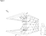
- the inventive load-bearing straw-bale wall system (1) comprises:
- the inventive system (1) also comprises at least one reinforcing member (10) which is fixed to the foundation (2) and the beam (9), placed onto at least one of the surfaces of the straw-bales (4) facing into the building or outside the building, and provides resistance of the straw-bales (4) to lateral loads.
- the reinforcing member (10) extends on the surface crosswise such that it will be connect to the compression members (8).
- the reinforcing member (10) is a reinforced-concrete construction rebar.
- the inventive system (1) also comprises at least one locking member (not shown in the figures) which is placed onto the reinforcing member (10) and prevents the compression member (8) from moving involuntarily by being locked after the straw-bale (4) is compressed in desired amount.
- the foundation (2) and the beam (9) included in the inventive system (1) preferably have a prism form such as rectangular prism, tetragonal prism made of reinforced-concrete.
- the foundation (2) and the beam (9) form structural tensioning system by being connected to one another indirectly via the connection member (5), the support member (6), the tension ring (7) and the compression member (8).
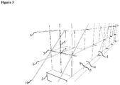
- the fixing member (3) included in the inventive system (1) is placed onto the foundation (2) and it enables the connection member (5) that is passed through the straw-bales (4) located on the foundation (2) to be fixed to the foundation (2).
- the fixing member (3) is placed on the lower surface of the beam (9) and it enables the connection member (5) that is passed through the straw-bales (4) located under the beam (9) to be fixed to the beam (9).
- the fixing member (3) is a hook made of a strong material such as iron, steel.
- the straw-bales (4) included in the inventive system (1) are placed on top of one another starting from the top of the foundation (2) until the desired height of the building being constructed is achieved.
- the straw-bales (4) are placed on top of one another such that they are lapped.
- connection member (5) included in the inventive system (1) is passed through the straw-bales (4) placed one after the other.
- the connection member (5) is passed through the straw-bales (4) by using straw-bale needle.
- the straw-bales (4) are compressed in order that they can carry loads such as roof load, snow load imposed onto the straw-bales (4) and they are not deformed under the load.
- connection member (5) passed through the straw-bales (4) ensures that the connection member (5) remains at a tension enabling to compress the straw-bales (4) upon it is connected to the fixing members (3) located on the foundation (2) and under the beam (9) and the tension rings (7) located on the pre-determined support members (6) after it is passed through the tension ring (7). Also, at least part of the connection member (5) passed through the straw-bales (4) projects from at least one of the surfaces of the straw-bales (4) facing into the building or outside the building. The compression member (8) is placed onto the said projecting part of the connection member (5).
- the connection member (5) is a rope made of a polypropylene material.
- the support member (6) included in the inventive system (1) is placed such that it will extend in a horizontal plane among the straw-bales (4) placed onto one another in order to compress the straw-bales (4).
- the support member (6) is a reinforced-concrete rebar being used in constructions frequently.
- the tension ring (7) included in the inventive system (1) is placed such that the pre-determined support members (6) will pass through the tension ring (7).
- the tension ring (7) enables to stretch the connection member (5) in order that the connection member (5) can compress the straw-bales (4).
- the tension ring (7) is a collar made of a metal material.
- the compression member (8) included in the inventive system (1) is placed into the part projecting from at least one of the surfaces of the connection member (5), which is passed through the straw-bales (4), facing into the building or outside the building.
- the compression member (8) ensures that the straw-bales (4) where the connection member (5) projects are compressed to a desired extend upon the compression member (8) is moved by being preferably rotated after it holds the projecting part of the connection member (5).
- the straw-bales (4) located in areas wherein there are openings such as window openings, door openings where the straw-bales (4) are subjected to different loads or wherein there are no openings such as building corner are compressed upon the compression member (8) stretches the connection member (5).
- the foundation (2) is placed onto the floor at first. Then, the first straw-bales (4) are placed onto the foundation (2).
- the connection member (5) By passing the connection member (5) through the first row straw-bales (4) via preferably a straw-bale needle while placing the first row straw-bales (4), the said connection member (5) is connected to the fixing member (3) located on the foundation (2) upon being passed through the tension rings (7) located on certain support members (6).
- connection member (5) laterally wraps the two straw-bales (4) one after the other by the compression member (8) projecting from between two straw-bales (4) from the upper region where the support member (6) is located, the lower region where the fixing member (3) is located.
- connection members (5) are also applied for other row straw-bales (4) in a way and line such as in the first two rows.
- the straw-bales (4) located in regions wherein different load will be imposed on the straw-bale (4) such as door openings and window openings in the building obtained enables to compress the connection member (5) whereto the compression member (8) is connected is compressed to a desired extend by compressing it more or less.
- strength of the building obtained is increased by placing crosswise and/or vertical reinforcing members (10) onto at least one of the surfaces of the straw-bales (4) facing into the building or outside the building.
- connection member (5) is prevented from effecting the compression amount of the related straw-bale (4) such by getting free from the compression member (8) involuntarily upon fixing the compression member (8) in a desired position by means of the locking member placed onto the said reinforcing member (10).
- the beam (9) enabling to close the upper surfaces of the said straw-bales (4), which are open outwards, onto the straw-bales (4) located on the top in the building obtained is placed.
- the beam (9) holds and compresses the straw-bales (4), which are located on the upper row, from above by means of the connection member (5) connected to the fixing member (3) located on the lower surface of thereof as such in the foundation (2).
- connection members (5) at different rows coincide with the support members (6) at different rows, a continuous connection is created from the foundation (2) to the beam (9) from top to bottom.
- accessories operate with traction whereas straw-bales (4) operate with pressure.
- the inventive wall system (1) is assembled, the system (1) is made monolithic by applying rough cast and final rendering onto the wire lath applied in the state of the art to the inner and outer surfaces of the straw-bales (4).
- inventive system (1) compression levels of the straw-bales (4) can be adjusted as a whole wall or locally in part.
- problems arising from the fact that the straw-bales known in the state of the art cannot be compressed adequately or they are compressed too much are overcome.
- inventive system (1) it is enabled to build a durable load-bearing straw-bale wall system (1) with less material and labour for less and quickly.
Landscapes
- Engineering & Computer Science (AREA)
- Architecture (AREA)
- Physics & Mathematics (AREA)
- Electromagnetism (AREA)
- Civil Engineering (AREA)
- Structural Engineering (AREA)
- Building Environments (AREA)
- Finishing Walls (AREA)
Claims (15)
- Un système (1) de paroi porteuse à bottes de paille utilisé dans la construction de bâtiments, permettant de séparer les bâtiments de l'environnement extérieur, comprenant :au moins une fondation (2) en béton armé qui est située sur le sol ;au moins un élément de fixation (3) qui est fixé sur la fondation (2) ;une pluralité de bottes de paille (4) qui sont placées sur la fondation (2) et qui sont agencées les unes et les autres de telle sorte qu'elles recouvrent entièrement la fondation (2) et qu'elles s'étendent sur une certaine hauteur ;au moins un élément de liaison (5) qui passe à travers les bottes de paille (4) placées sur la fondation (2) et qui est tel, avec celles-ci, qu'au moins une partie de lui dépasse des bottes de paille (4), procure une résistance des bottes de paille (4) aux charges imposées à celles-ci par compression, et est relié à l'élément de fixation (3) après son passage à travers les bottes de paille (4) placées sur la fondation (2) ;au moins un élément de support (6) qui est placé sur les bottes de paille (4) de telle sorte qu'il s'étende entre les bottes de paille (4) placées les unes sur les autres ;au moins une poutre (9) qui est placée sur lesdites bottes de paille (4) de telle sorte qu'elle recouvre la dernière rangée de bottes de paille (4) située sur le dessus ;au moins un élément de compression (8), auquel l'élément de liaison (5) faisant saillie des bottes de paille (4) est fixé et qui permet de comprimer les bottes de paille (4), l'élément de liaison (5) s'étendant selon un degré souhaité après que l'élément de liaison (5) soit fixé sur celui-ci ;caractérisé en ce qu'il comprend en outre :
au moins un anneau de tension (7) dans lequel les éléments de support (6) passent et qui tente de tirer l'élément de liaison (5) passant au travers de lui. - Un système (1) selon la revendication 1, caractérisé par au moins un élément de renforcement (10) qui est fixé à la fondation (2) et à la poutre (9), placé sur au moins une des surfaces des bottes de paille (4) orientées vers l'intérieur ou l'extérieur du bâtiment, et qui procure une résistance des bottes de paille (4) aux charges latérales.
- Un système (1) selon la revendication 2, caractérisé par au moins un élément de renforcement (10) qui s'étend sur la surface transversalement de manière à être relié aux éléments de compression (8).
- Un système (1) selon la revendication 2 ou la revendication 3, caractérisé par au moins un élément de renforcement (10) qui est une barre de construction en béton armé.
- Un système (1) selon l'une quelconque des revendications 2 à 4, caractérisé par au moins un élément de verrouillage qui est placé sur l'élément de renforcement (10) et empêche l'élément de compression (8) de se déplacer involontairement en étant verrouillé après compression de la botte de paille (4) selon un degré souhaité.
- Un système (1) selon l'une quelconque des revendications précédentes, caractérisé par l'élément de fixation (3) qui est placé sur la surface inférieure de la poutre (9) et qui permet à l'élément de liaison (5), qui passe à travers les bottes de paille (4) situées sous la poutre (9), d'être fixé à la poutre (9).
- Un système (1) selon l'une quelconque des revendications précédentes, caractérisé par le fait que l'élément de fixation (3) est un crochet.
- Un système (1) selon l'une quelconque des revendications précédentes, caractérisé par le fait que les bottes de paille (4) sont placées les unes sur les autres de manière à être en chevauchement.
- Un système (1) selon l'une quelconque des revendications précédentes, caractérisé par le fait que l'élément de liaison (5) qui assure qu'il reste sous une tension permettant de comprimer les bottes de paille (4) lorsqu'il est relié aux éléments de fixation (3) situés sur la fondation (2) et sous la poutre (9) et les anneaux de tension (7) situés sur les éléments de support (6) prédéterminés après qu'il soit passé au travers de l'anneau de tension (7).
- Un système (1) selon l'une quelconque des revendications précédentes, caractérisé par le fait que l'élément de connexion (5) est un cordage fait d'un matériau polypropylène.
- Un système (1) selon l'une quelconque des revendications précédentes, caractérisé par le fait que l'anneau de tension (7) traverse des éléments de support prédéterminés (6) de telle sorte qu'il saisit les éléments de support (6).
- Un système (1) selon l'une quelconque des revendications précédentes, caractérisé par le fait que l'anneau de tension (7) assure que l'élément de liaison (5) est fixé de telle sorte que l'élément de liaison (5) ait une tension suffisante pour comprimer les bottes de paille (4).
- Un système (1) selon la revendication 11 ou la revendication 12, caractérisé par le fait que l'anneau de tension (7) est un collier fait en un matériau métallique.
- Un système (1) selon l'une quelconque des revendications précédentes, caractérisé par le fait que l'élément de compression (8) est placé dans la partie dépassant d'au moins une des surfaces de l'élément de liaison (5), qui passe à travers les bottes de paille (4), tournée vers le bâtiment ou vers l'extérieur du bâtiment.
- Un système (1) selon la revendication 14, caractérisé par le fait que l'élément de compression (8) assure que les bottes de paille (4) dans lesquelles l'élément de liaison (5) reste, sont comprimées jusqu'à un degré souhaitée lorsqu'il est étiré en étant tourné après qu'il soit placé sur la partie en saillie de l'élément de liaison (5).
Applications Claiming Priority (2)
| Application Number | Priority Date | Filing Date | Title |
|---|---|---|---|
| TR2015/11158A TR201511158A2 (tr) | 2015-09-08 | 2015-09-08 | Bi̇r yiğma saman balyasi duvar si̇stemi̇ |
| PCT/TR2016/000124 WO2017044056A1 (fr) | 2015-09-08 | 2016-09-07 | Système de paroi porte-charge destiné à des balles de paille |
Publications (2)
| Publication Number | Publication Date |
|---|---|
| EP3347534A1 EP3347534A1 (fr) | 2018-07-18 |
| EP3347534B1 true EP3347534B1 (fr) | 2019-11-20 |
Family
ID=57227065
Family Applications (1)
| Application Number | Title | Priority Date | Filing Date |
|---|---|---|---|
| EP16790755.9A Active EP3347534B1 (fr) | 2015-09-08 | 2016-09-07 | Système de paroi porte-charge destiné à des balles de paille |
Country Status (3)
| Country | Link |
|---|---|
| EP (1) | EP3347534B1 (fr) |
| TR (1) | TR201511158A2 (fr) |
| WO (1) | WO2017044056A1 (fr) |
Families Citing this family (1)
| Publication number | Priority date | Publication date | Assignee | Title |
|---|---|---|---|---|
| TR201809089A2 (tr) * | 2018-06-27 | 2018-07-23 | T C Istanbul Kueltuer Ueniversitesi | Diş etkenlere dayanikli bi̇r yiğma saman balyasi duvar si̇stemi̇ |
Family Cites Families (4)
| Publication number | Priority date | Publication date | Assignee | Title |
|---|---|---|---|---|
| US5749199A (en) * | 1996-09-19 | 1998-05-12 | Bale Built, Inc. | Fiber bale composite structural building system |
| US6061986A (en) * | 1998-05-06 | 2000-05-16 | Canada; Larry | Reinforced stucco panel and straw insulator wall assembly |
| KR20120131465A (ko) | 2011-05-25 | 2012-12-05 | 이용식 | 스트로베일 벽체 구조 및 이를 이용한 시공 방법 |
| CN203716285U (zh) | 2014-01-17 | 2014-07-16 | 天津乡景建筑工程有限公司 | 一种自承重型草砖房 |
-
2015
- 2015-09-08 TR TR2015/11158A patent/TR201511158A2/tr unknown
-
2016
- 2016-09-07 WO PCT/TR2016/000124 patent/WO2017044056A1/fr not_active Ceased
- 2016-09-07 EP EP16790755.9A patent/EP3347534B1/fr active Active
Non-Patent Citations (1)
| Title |
|---|
| None * |
Also Published As
| Publication number | Publication date |
|---|---|
| EP3347534A1 (fr) | 2018-07-18 |
| TR201511158A2 (tr) | 2016-08-22 |
| WO2017044056A1 (fr) | 2017-03-16 |
Similar Documents
| Publication | Publication Date | Title |
|---|---|---|
| US7073306B1 (en) | Method of building | |
| US20110167749A1 (en) | flexible interlocking mortarless wall unit and construction method | |
| CN102245529B (zh) | 利用灰泥建造的轻质房屋结构及其生产方法 | |
| BG100624A (bg) | Противоземетръсен,ветроустойчив,пожароустойчив,полуготов строителен панел и изградени с него конструкции | |
| WO2013064150A1 (fr) | Unité de construction servant d'abri immédiat ou permanent | |
| CN107130757A (zh) | 蒸压轻质加气混凝土大板组件 | |
| US5305576A (en) | Method of constructing curvilinear structures | |
| WO2017219063A1 (fr) | Procédé de construction d'un plancher en béton dans un bâtiment à plusieurs étages | |
| KR101286278B1 (ko) | 한옥지붕구조 | |
| US10640970B2 (en) | Concrete building elements and assemblies thereof, and related methods | |
| JP2008231904A (ja) | 高床式建築物の基礎・基礎柱・土台の施工法 | |
| US5566520A (en) | Integrated precast concrete forming system | |
| US1259698A (en) | Reinforced concrete. | |
| US4161852A (en) | Adobe wall construction | |
| RU2552506C1 (ru) | Способ возведения монолитных конструкций зданий и несъёмная универсальная модульная опалубочная система | |
| WO2017044056A1 (fr) | Système de paroi porte-charge destiné à des balles de paille | |
| US6557830B2 (en) | Prefabricated masonry fence system and method for constructing same | |
| WO2020040714A2 (fr) | Système de paroi porte-charge destiné à des balles de paille et résistant à des conditions extérieures | |
| JP5508566B2 (ja) | コンクリート・コンテナハウスの建築施工方法 | |
| JP2018135703A (ja) | 塀構造、塀材及び塀の構築方法 | |
| KR20120035617A (ko) | 이동식 목조건축물 | |
| JP6767552B1 (ja) | ウッドフェンスのストレートピン工法 | |
| KR20160030029A (ko) | 이동식 가옥 | |
| JP2008223461A (ja) | 高床式建築物の基礎・基礎柱・土台の施工法 | |
| CN211007033U (zh) | 一种竖向墙全部现浇和水平结构预制的建筑结构 |
Legal Events
| Date | Code | Title | Description |
|---|---|---|---|
| STAA | Information on the status of an ep patent application or granted ep patent |
Free format text: STATUS: UNKNOWN |
|
| STAA | Information on the status of an ep patent application or granted ep patent |
Free format text: STATUS: THE INTERNATIONAL PUBLICATION HAS BEEN MADE |
|
| PUAI | Public reference made under article 153(3) epc to a published international application that has entered the european phase |
Free format text: ORIGINAL CODE: 0009012 |
|
| STAA | Information on the status of an ep patent application or granted ep patent |
Free format text: STATUS: REQUEST FOR EXAMINATION WAS MADE |
|
| 17P | Request for examination filed |
Effective date: 20180409 |
|
| AK | Designated contracting states |
Kind code of ref document: A1 Designated state(s): AL AT BE BG CH CY CZ DE DK EE ES FI FR GB GR HR HU IE IS IT LI LT LU LV MC MK MT NL NO PL PT RO RS SE SI SK SM TR |
|
| AX | Request for extension of the european patent |
Extension state: BA ME |
|
| DAV | Request for validation of the european patent (deleted) | ||
| DAX | Request for extension of the european patent (deleted) | ||
| STAA | Information on the status of an ep patent application or granted ep patent |
Free format text: STATUS: EXAMINATION IS IN PROGRESS |
|
| 17Q | First examination report despatched |
Effective date: 20190104 |
|
| GRAP | Despatch of communication of intention to grant a patent |
Free format text: ORIGINAL CODE: EPIDOSNIGR1 |
|
| STAA | Information on the status of an ep patent application or granted ep patent |
Free format text: STATUS: GRANT OF PATENT IS INTENDED |
|
| INTG | Intention to grant announced |
Effective date: 20190703 |
|
| GRAS | Grant fee paid |
Free format text: ORIGINAL CODE: EPIDOSNIGR3 |
|
| GRAA | (expected) grant |
Free format text: ORIGINAL CODE: 0009210 |
|
| STAA | Information on the status of an ep patent application or granted ep patent |
Free format text: STATUS: THE PATENT HAS BEEN GRANTED |
|
| AK | Designated contracting states |
Kind code of ref document: B1 Designated state(s): AL AT BE BG CH CY CZ DE DK EE ES FI FR GB GR HR HU IE IS IT LI LT LU LV MC MK MT NL NO PL PT RO RS SE SI SK SM TR |
|
| REG | Reference to a national code |
Ref country code: GB Ref legal event code: FG4D |
|
| REG | Reference to a national code |
Ref country code: CH Ref legal event code: EP |
|
| REG | Reference to a national code |
Ref country code: IE Ref legal event code: FG4D |
|
| REG | Reference to a national code |
Ref country code: DE Ref legal event code: R096 Ref document number: 602016024783 Country of ref document: DE |
|
| REG | Reference to a national code |
Ref country code: AT Ref legal event code: REF Ref document number: 1204337 Country of ref document: AT Kind code of ref document: T Effective date: 20191215 |
|
| REG | Reference to a national code |
Ref country code: NL Ref legal event code: FP |
|
| REG | Reference to a national code |
Ref country code: LT Ref legal event code: MG4D |
|
| PG25 | Lapsed in a contracting state [announced via postgrant information from national office to epo] |
Ref country code: SE Free format text: LAPSE BECAUSE OF FAILURE TO SUBMIT A TRANSLATION OF THE DESCRIPTION OR TO PAY THE FEE WITHIN THE PRESCRIBED TIME-LIMIT Effective date: 20191120 Ref country code: LV Free format text: LAPSE BECAUSE OF FAILURE TO SUBMIT A TRANSLATION OF THE DESCRIPTION OR TO PAY THE FEE WITHIN THE PRESCRIBED TIME-LIMIT Effective date: 20191120 Ref country code: LT Free format text: LAPSE BECAUSE OF FAILURE TO SUBMIT A TRANSLATION OF THE DESCRIPTION OR TO PAY THE FEE WITHIN THE PRESCRIBED TIME-LIMIT Effective date: 20191120 Ref country code: NO Free format text: LAPSE BECAUSE OF FAILURE TO SUBMIT A TRANSLATION OF THE DESCRIPTION OR TO PAY THE FEE WITHIN THE PRESCRIBED TIME-LIMIT Effective date: 20200220 Ref country code: GR Free format text: LAPSE BECAUSE OF FAILURE TO SUBMIT A TRANSLATION OF THE DESCRIPTION OR TO PAY THE FEE WITHIN THE PRESCRIBED TIME-LIMIT Effective date: 20200221 Ref country code: BG Free format text: LAPSE BECAUSE OF FAILURE TO SUBMIT A TRANSLATION OF THE DESCRIPTION OR TO PAY THE FEE WITHIN THE PRESCRIBED TIME-LIMIT Effective date: 20200220 Ref country code: FI Free format text: LAPSE BECAUSE OF FAILURE TO SUBMIT A TRANSLATION OF THE DESCRIPTION OR TO PAY THE FEE WITHIN THE PRESCRIBED TIME-LIMIT Effective date: 20191120 |
|
| PG25 | Lapsed in a contracting state [announced via postgrant information from national office to epo] |
Ref country code: HR Free format text: LAPSE BECAUSE OF FAILURE TO SUBMIT A TRANSLATION OF THE DESCRIPTION OR TO PAY THE FEE WITHIN THE PRESCRIBED TIME-LIMIT Effective date: 20191120 Ref country code: RS Free format text: LAPSE BECAUSE OF FAILURE TO SUBMIT A TRANSLATION OF THE DESCRIPTION OR TO PAY THE FEE WITHIN THE PRESCRIBED TIME-LIMIT Effective date: 20191120 Ref country code: IS Free format text: LAPSE BECAUSE OF FAILURE TO SUBMIT A TRANSLATION OF THE DESCRIPTION OR TO PAY THE FEE WITHIN THE PRESCRIBED TIME-LIMIT Effective date: 20200320 |
|
| PG25 | Lapsed in a contracting state [announced via postgrant information from national office to epo] |
Ref country code: AL Free format text: LAPSE BECAUSE OF FAILURE TO SUBMIT A TRANSLATION OF THE DESCRIPTION OR TO PAY THE FEE WITHIN THE PRESCRIBED TIME-LIMIT Effective date: 20191120 |
|
| PG25 | Lapsed in a contracting state [announced via postgrant information from national office to epo] |
Ref country code: CZ Free format text: LAPSE BECAUSE OF FAILURE TO SUBMIT A TRANSLATION OF THE DESCRIPTION OR TO PAY THE FEE WITHIN THE PRESCRIBED TIME-LIMIT Effective date: 20191120 Ref country code: RO Free format text: LAPSE BECAUSE OF FAILURE TO SUBMIT A TRANSLATION OF THE DESCRIPTION OR TO PAY THE FEE WITHIN THE PRESCRIBED TIME-LIMIT Effective date: 20191120 Ref country code: DK Free format text: LAPSE BECAUSE OF FAILURE TO SUBMIT A TRANSLATION OF THE DESCRIPTION OR TO PAY THE FEE WITHIN THE PRESCRIBED TIME-LIMIT Effective date: 20191120 Ref country code: EE Free format text: LAPSE BECAUSE OF FAILURE TO SUBMIT A TRANSLATION OF THE DESCRIPTION OR TO PAY THE FEE WITHIN THE PRESCRIBED TIME-LIMIT Effective date: 20191120 Ref country code: PT Free format text: LAPSE BECAUSE OF FAILURE TO SUBMIT A TRANSLATION OF THE DESCRIPTION OR TO PAY THE FEE WITHIN THE PRESCRIBED TIME-LIMIT Effective date: 20200412 Ref country code: ES Free format text: LAPSE BECAUSE OF FAILURE TO SUBMIT A TRANSLATION OF THE DESCRIPTION OR TO PAY THE FEE WITHIN THE PRESCRIBED TIME-LIMIT Effective date: 20191120 |
|
| REG | Reference to a national code |
Ref country code: AT Ref legal event code: MK05 Ref document number: 1204337 Country of ref document: AT Kind code of ref document: T Effective date: 20191120 |
|
| REG | Reference to a national code |
Ref country code: DE Ref legal event code: R097 Ref document number: 602016024783 Country of ref document: DE |
|
| PG25 | Lapsed in a contracting state [announced via postgrant information from national office to epo] |
Ref country code: SK Free format text: LAPSE BECAUSE OF FAILURE TO SUBMIT A TRANSLATION OF THE DESCRIPTION OR TO PAY THE FEE WITHIN THE PRESCRIBED TIME-LIMIT Effective date: 20191120 Ref country code: SM Free format text: LAPSE BECAUSE OF FAILURE TO SUBMIT A TRANSLATION OF THE DESCRIPTION OR TO PAY THE FEE WITHIN THE PRESCRIBED TIME-LIMIT Effective date: 20191120 |
|
| PLBE | No opposition filed within time limit |
Free format text: ORIGINAL CODE: 0009261 |
|
| STAA | Information on the status of an ep patent application or granted ep patent |
Free format text: STATUS: NO OPPOSITION FILED WITHIN TIME LIMIT |
|
| 26N | No opposition filed |
Effective date: 20200821 |
|
| PG25 | Lapsed in a contracting state [announced via postgrant information from national office to epo] |
Ref country code: PL Free format text: LAPSE BECAUSE OF FAILURE TO SUBMIT A TRANSLATION OF THE DESCRIPTION OR TO PAY THE FEE WITHIN THE PRESCRIBED TIME-LIMIT Effective date: 20191120 Ref country code: SI Free format text: LAPSE BECAUSE OF FAILURE TO SUBMIT A TRANSLATION OF THE DESCRIPTION OR TO PAY THE FEE WITHIN THE PRESCRIBED TIME-LIMIT Effective date: 20191120 Ref country code: AT Free format text: LAPSE BECAUSE OF FAILURE TO SUBMIT A TRANSLATION OF THE DESCRIPTION OR TO PAY THE FEE WITHIN THE PRESCRIBED TIME-LIMIT Effective date: 20191120 |
|
| PG25 | Lapsed in a contracting state [announced via postgrant information from national office to epo] |
Ref country code: IT Free format text: LAPSE BECAUSE OF FAILURE TO SUBMIT A TRANSLATION OF THE DESCRIPTION OR TO PAY THE FEE WITHIN THE PRESCRIBED TIME-LIMIT Effective date: 20191120 |
|
| REG | Reference to a national code |
Ref country code: DE Ref legal event code: R119 Ref document number: 602016024783 Country of ref document: DE |
|
| REG | Reference to a national code |
Ref country code: CH Ref legal event code: PL |
|
| GBPC | Gb: european patent ceased through non-payment of renewal fee |
Effective date: 20200907 |
|
| REG | Reference to a national code |
Ref country code: BE Ref legal event code: MM Effective date: 20200930 |
|
| PG25 | Lapsed in a contracting state [announced via postgrant information from national office to epo] |
Ref country code: LU Free format text: LAPSE BECAUSE OF NON-PAYMENT OF DUE FEES Effective date: 20200907 |
|
| PG25 | Lapsed in a contracting state [announced via postgrant information from national office to epo] |
Ref country code: DE Free format text: LAPSE BECAUSE OF NON-PAYMENT OF DUE FEES Effective date: 20210401 Ref country code: FR Free format text: LAPSE BECAUSE OF NON-PAYMENT OF DUE FEES Effective date: 20200930 |
|
| PG25 | Lapsed in a contracting state [announced via postgrant information from national office to epo] |
Ref country code: CH Free format text: LAPSE BECAUSE OF NON-PAYMENT OF DUE FEES Effective date: 20200930 Ref country code: BE Free format text: LAPSE BECAUSE OF NON-PAYMENT OF DUE FEES Effective date: 20200930 Ref country code: LI Free format text: LAPSE BECAUSE OF NON-PAYMENT OF DUE FEES Effective date: 20200930 Ref country code: GB Free format text: LAPSE BECAUSE OF NON-PAYMENT OF DUE FEES Effective date: 20200907 Ref country code: IE Free format text: LAPSE BECAUSE OF NON-PAYMENT OF DUE FEES Effective date: 20200907 |
|
| PG25 | Lapsed in a contracting state [announced via postgrant information from national office to epo] |
Ref country code: TR Free format text: LAPSE BECAUSE OF FAILURE TO SUBMIT A TRANSLATION OF THE DESCRIPTION OR TO PAY THE FEE WITHIN THE PRESCRIBED TIME-LIMIT Effective date: 20191120 Ref country code: MT Free format text: LAPSE BECAUSE OF FAILURE TO SUBMIT A TRANSLATION OF THE DESCRIPTION OR TO PAY THE FEE WITHIN THE PRESCRIBED TIME-LIMIT Effective date: 20191120 Ref country code: CY Free format text: LAPSE BECAUSE OF FAILURE TO SUBMIT A TRANSLATION OF THE DESCRIPTION OR TO PAY THE FEE WITHIN THE PRESCRIBED TIME-LIMIT Effective date: 20191120 |
|
| PG25 | Lapsed in a contracting state [announced via postgrant information from national office to epo] |
Ref country code: MK Free format text: LAPSE BECAUSE OF FAILURE TO SUBMIT A TRANSLATION OF THE DESCRIPTION OR TO PAY THE FEE WITHIN THE PRESCRIBED TIME-LIMIT Effective date: 20191120 Ref country code: MC Free format text: LAPSE BECAUSE OF FAILURE TO SUBMIT A TRANSLATION OF THE DESCRIPTION OR TO PAY THE FEE WITHIN THE PRESCRIBED TIME-LIMIT Effective date: 20191120 |
|
| PGFP | Annual fee paid to national office [announced via postgrant information from national office to epo] |
Ref country code: NL Payment date: 20220920 Year of fee payment: 7 |
|
| REG | Reference to a national code |
Ref country code: NL Ref legal event code: MM Effective date: 20231001 |
|
| PG25 | Lapsed in a contracting state [announced via postgrant information from national office to epo] |
Ref country code: NL Free format text: LAPSE BECAUSE OF NON-PAYMENT OF DUE FEES Effective date: 20231001 |
|
| PG25 | Lapsed in a contracting state [announced via postgrant information from national office to epo] |
Ref country code: NL Free format text: LAPSE BECAUSE OF NON-PAYMENT OF DUE FEES Effective date: 20231001 |