EP3348010B1 - Accès multiple dans un système de communication spatial temporel-fréquentiel orthogonal - Google Patents
Accès multiple dans un système de communication spatial temporel-fréquentiel orthogonal Download PDFInfo
- Publication number
- EP3348010B1 EP3348010B1 EP16845070.8A EP16845070A EP3348010B1 EP 3348010 B1 EP3348010 B1 EP 3348010B1 EP 16845070 A EP16845070 A EP 16845070A EP 3348010 B1 EP3348010 B1 EP 3348010B1
- Authority
- EP
- European Patent Office
- Prior art keywords
- time
- otfs
- symbols
- frequency
- grid
- Prior art date
- Legal status (The legal status is an assumption and is not a legal conclusion. Google has not performed a legal analysis and makes no representation as to the accuracy of the status listed.)
- Active
Links
Images

























Classifications
-
- H—ELECTRICITY
- H04—ELECTRIC COMMUNICATION TECHNIQUE
- H04L—TRANSMISSION OF DIGITAL INFORMATION, e.g. TELEGRAPHIC COMMUNICATION
- H04L27/00—Modulated-carrier systems
- H04L27/26—Systems using multi-frequency codes
- H04L27/2601—Multicarrier modulation systems
- H04L27/2697—Multicarrier modulation systems in combination with other modulation techniques
-
- H—ELECTRICITY
- H04—ELECTRIC COMMUNICATION TECHNIQUE
- H04L—TRANSMISSION OF DIGITAL INFORMATION, e.g. TELEGRAPHIC COMMUNICATION
- H04L1/00—Arrangements for detecting or preventing errors in the information received
- H04L1/0001—Systems modifying transmission characteristics according to link quality, e.g. power backoff
- H04L1/0023—Systems modifying transmission characteristics according to link quality, e.g. power backoff characterised by the signalling
-
- H—ELECTRICITY
- H04—ELECTRIC COMMUNICATION TECHNIQUE
- H04L—TRANSMISSION OF DIGITAL INFORMATION, e.g. TELEGRAPHIC COMMUNICATION
- H04L1/00—Arrangements for detecting or preventing errors in the information received
- H04L1/004—Arrangements for detecting or preventing errors in the information received by using forward error control
- H04L1/0056—Systems characterized by the type of code used
- H04L1/0071—Use of interleaving
-
- H—ELECTRICITY
- H04—ELECTRIC COMMUNICATION TECHNIQUE
- H04L—TRANSMISSION OF DIGITAL INFORMATION, e.g. TELEGRAPHIC COMMUNICATION
- H04L27/00—Modulated-carrier systems
- H04L27/26—Systems using multi-frequency codes
- H04L27/2601—Multicarrier modulation systems
- H04L27/2626—Arrangements specific to the transmitter only
- H04L27/2627—Modulators
- H04L27/2639—Modulators using other transforms, e.g. discrete cosine transforms, Orthogonal Time Frequency and Space [OTFS] or hermetic transforms
-
- H—ELECTRICITY
- H04—ELECTRIC COMMUNICATION TECHNIQUE
- H04L—TRANSMISSION OF DIGITAL INFORMATION, e.g. TELEGRAPHIC COMMUNICATION
- H04L5/00—Arrangements affording multiple use of the transmission path
- H04L5/0001—Arrangements for dividing the transmission path
- H04L5/0003—Two-dimensional division
- H04L5/0005—Time-frequency
-
- H—ELECTRICITY
- H04—ELECTRIC COMMUNICATION TECHNIQUE
- H04J—MULTIPLEX COMMUNICATION
- H04J11/00—Orthogonal multiplex systems, e.g. using WALSH codes
Definitions
- This disclosure generally relates to communications protocols and methods, and more particularly relates to methods for modulation and related processing of signals used for wireless and other forms of communication.
- next generation systems will need to improve the quality of data delivery in order to support desired future applications.
- the public is increasingly coming to expect that wireless networks provide a near "wireline" experience to the untethered user. This may translate to, for example, a requirement of 50+ Mbps throughout coverage areas (i.e., even at cell edges), which will require advanced interference mitigation technologies to be realized.
- US2014/161154 discloses a method for modulating data for transmission within a communication system.
- the method includes establishing a time-frequency shifting matrix of dimension N ⁇ N, wherein N is greater than one.
- the method further includes combining the time-frequency shifting matrix with a data frame to provide an intermediate data frame.
- a transformed data matrix is provided by permuting elements of the intermediate data frame.
- a modulated signal is generated in accordance with elements of the transformed data matrix.
- a signal modulation method as defined in claim 1.
- a signal demodulation method as defined in claim 8.
- a communication device as defined in claim 9.
- a communication device as defined in claim 14.
- the disclosure is directed to a signal modulation method.
- the method includes receiving a first set of data symbols and a second set of data symbols defined with respect to a lattice in a two-dimensional information domain wherein the first set of data symbols is associated with a first user and the second set of data symbols is associated with a second user.
- the method further includes spreading each first data symbol of the first set of data symbols onto a first set of grid points in a time-frequency domain wherein each first data symbol is spread by a two-dimensional basis function uniquely associated with a position on the lattice corresponding to the first data symbol, thereby transforming the first set of data symbols into a first set of transformed symbols.
- Each second data symbol of the second set of data symbols is also spread onto a second set of grid points in the time-frequency domain wherein the first set of grid points are different from the second set of grid points .
- each second data symbol is spread by a two-dimensional basis function uniquely associated with a position on the lattice corresponding to the second data symbol, thereby transforming the second set of data symbols into a second set of transformed symbols.
- a modulated signal is then generated using the first set of transformed symbols and the second set of transformed symbols.
- the two-dimensional information domain corresponds to a delay-Doppler domain.
- the first set of grid points may be interleaved with the second set of grid points in the time-frequency domain.
- the first set of grid points may form a first window within the time-frequency domain and the second set of grid points may form a second window within the time-frequency domain contiguous with the first window.
- one or both of the first and second windows may be divided into multiple components and arranged non-contiguously in a time-frequency window within the time-frequency domain.
- the first set of grid points may form a first subsampled grid of a time-frequency frame within the time-frequency domain and the second set of grid points may form a second subsampled grid of the time frequency frame.
- the first subsampled grid and the second subsampled grid may be of substantially the same time and frequency span as the time-frequency frame.
- the method may include receiving first channel state information associated with the first user and positioning a first window containing the first set of grid points within the time-frequency domain based upon the first channel state information.
- the disclosure is also directed to a signal demodulation method.
- the method includes receiving a modulated signal generated using a first set of transformed symbols corresponding to a first user and a second set of transformed symbols corresponding to a second user.
- the first set of transformed symbols may be associated with a first set of grid points in a time-frequency domain and the second set of transformed symbols may be associated with a second set of grid points in the time-frequency domain, the first set of grid points being different from the second set of grid points.
- the method further includes despreading the first set of transformed symbols into a first set of data symbols using a first plurality of two-dimensional basis functions, each two-dimensional basis function of the first plurality of two-dimensional basis functions being uniquely associated with one data symbol of the first set of data symbols and with a position on a lattice in a two-dimensional information domain.
- the signal demodulation method may further include despreading the second set of transformed symbols into a second set of data symbols using a second plurality of two-dimensional basis functions, each two-dimensional basis function of the second plurality of two-dimensional basis functions being uniquely associated with one data symbol of the second set of data symbols and with a different position on the lattice.
- the disclosure also pertains to a communication device including a wireless transmitter, a processor, and a memory including program code executable by the processor.
- the program code includes code for causing the processor to receive a first set of data symbols and a second set of data symbols defined with respect to a lattice in a two-dimensional information domain wherein the first set of data symbols is associated with a first user and the second set of data symbols is associated with a second user.
- the code may further cause the processor to spread each first data symbol of the first set of data symbols onto a first set of grid points in a time-frequency domain wherein each first data symbol is spread by a two-dimensional basis function uniquely associated with a position on the lattice corresponding to the first data symbol, thereby transforming the first set of data symbols into a first set of transformed symbols.
- the processor may also be configured by the code to spread each second data symbol of the second set of data symbols onto a second set of grid points in the time-frequency domain wherein the first set of grid points are different from the second set of grid points.
- each second data symbol is spread by a two-dimensional basis function uniquely associated with a position on the lattice corresponding to the second data symbol, thereby transforming the second set of data symbols into a second set of transformed symbols.
- the processor may provide the first set of transformed symbols and the second set of transformed symbols to the transmitter, wherein the transmitter is configured to generate a modulated signal using the first set of transformed symbols and the second set of transformed symbol.
- the disclosure pertains to a communication device including a wireless receiver, a processor, and a memory including program code executable by the processor.
- the program code includes code for causing the processor to receive, from the wireless receiver, a modulated signal received by the wireless receiver, the modulated signal having been generated using a first set of transformed symbols corresponding to a first user and a second set of transformed symbols corresponding to a second user.
- the first set of transformed symbols are associated with a first set of grid points in a time-frequency domain and wherein the second set of transformed symbols are associated with a second set of grid points in the time-frequency domain, the first set of grid points being different from the second set of grid points.
- the processor is further configured by the code to despread the first set of transformed symbols into a first set of data symbols using a first plurality of two-dimensional basis functions, each two-dimensional basis function of the first plurality of two-dimensional basis functions being uniquely associated with one data symbol of the first set of data symbols and with a position on a lattice in a two-dimensional information domain.
- the disclosure is directed to a method of transmitting data over a communication channel.
- the method includes receiving a plurality of information symbols.
- the method further includes encoding an NxM array containing the plurality of information symbols into a two-dimensional array of modulation symbols by spreading each of the plurality of information symbols with respect to both time and frequency.
- the two-dimensional array of modulation symbols is then transmitted using M mutually orthogonal waveforms included within M frequency sub-bands
- the encoding may further include transforming the NxM array into an array of filtered OFDM symbols using at least one Fourier transform and a filtering process and transforming the array of filtered OFDM symbols into an array of OTFS symbols using at least one two-dimensional Fourier transform.
- the disclosure pertains to a communication device including a wireless receiver configured to receive one or more modulated waveforms, a processor and a memory including program code executable by the processor.
- the program code includes code for causing the processor to receive, from the wireless receiver, samples of one or more modulated waveforms.
- the code further includes code for causing the processor to matched filter samples of the one or more modulated waveforms with respect to a receive pulse to produce estimated time-frequency modulation symbols.
- Each of the estimated time-frequency modulation symbols corresponds to modulation of one of a plurality of orthogonal two-dimensional basis functions by one of a plurality of information symbols.
- the program code further includes code for causing the processor to project the estimated time-frequency modulation symbols on the plurality of orthogonal two-dimensional basis functions in order to obtain estimates of the plurality of information symbols.
- the program code may further include code for performing windowing and periodization operations with respect to the estimated time-frequency modulation symbols.
- the code may include code for causing the processor to perform a symplectic Fourier transform operation with respect to a periodic sequence comprised of the estimated time-frequency modulation symbols.
- the disclosure is also directed to a method of transmitting data over a communication channel.
- the method includes receiving a plurality of information symbols and encoding an NxM array containing the plurality of information symbols into a two-dimensional array of OTFS modulation symbols by spreading each of the plurality of information symbols with respect to both time and frequency.
- the array of OTFS modulation symbols is arranged in a time frequency frame along with one or more OFDM symbols.
- the method further includes transmitting the two-dimensional array of OTFS modulation symbols using M narrowband subcarriers.
- the one or more OFDM symbols are then transmitted using at least one OFDM subcarrier.
- the disclosure further pertains to a communication device including a wireless transmitter, a processor and a memory including program code executable by the processor.
- the program code includes code for causing the processor to receive a plurality of information symbols; and encode an NxM array containing the plurality of information symbols into a two-dimensional array of OTFS modulation symbols by spreading each of the plurality of information symbols with respect to both time and frequency.
- the array of OTFS modulation symbols is arranged in a time frequency frame along with one or more OFDM symbols.
- the program code further includes code for transmitting the two-dimensional array of OTFS modulation symbols using M narrowband subcarriers and for transmitting the one or more OFDM symbols using at least one OFDM subcarrier.
- the disclosure relates to a method of receiving data transmitted over a communication channel.
- the method includes receiving M mutually orthogonal waveforms included within M frequency sub-bands and receiving at least one OFDM pilot symbol included within a frequency sub-band.
- the method further includes demodulating the M mutually orthogonal waveforms to recover an estimate of a two-dimensional array of OTFS symbols.
- a two-dimensional equalizer is then configured based at least in part upon the at least one OFDM pilot symbol.
- the method further includes decoding the two-dimensional array of OTFS symbols in order to generate an estimate of an NxM array containing a plurality of information symbols, the NxM array having been encoded prior to transmission of the data by spreading each of the plurality of information symbols with respect to both time and frequency.
- the estimate of the NxM array may then be processed using the two-dimensional equalizer in order to obtain an equalized estimate of the NxM array.
- the disclosure is further directed to a method of providing a modulated signal useable in a signal transmission system.
- the method includes performing a two dimensional time-frequency transformation of a data frame including a plurality of information symbols to generate a frame of OTFS modulation symbols arranged within a time-frequency plane wherein a plurality of OFDM symbols are also arranged within the time-frequency plane.
- the method further includes generating, using an OFDM modulator, the modulated signal based upon the frame of OTFS modulation symbols and the plurality of OFDM symbols.
- the method includes receiving a plurality of signal components of the modulated signal and generating, by performing an OFDM demodulation operation using the plurality of signal components, a plane of estimated time-frequency modulation symbols.
- the method further includes providing an estimated OTFS data frame by performing an inverse of a two dimensional time-frequency transformation with respect to ones of the estimated time-frequency modulation symbols wherein other of the estimated time-frequency modulation symbols are OFDM symbols.
- the disclosure also pertains to a receiver apparatus including a receiver front end.
- Thee receiver front end is configured to receive a plurality of signal components of a modulated signal.
- An OFDM demodulator is configured to generate a plane of estimated time-frequency modulation symbols based upon the plurality of signal components.
- An OTFS post-processing unit is operative to provide an estimated OTFS data frame, the OTFS post-processing unit performing an inverse of a two dimensional time-frequency transformation with respect to ones of the estimated time-frequency modulation symbols wherein other of the estimated time-frequency modulation symbols are OFDM symbols.
- embodiments of orthogonal time frequency space (OTFS) modulation involve transmitting each information symbol by modulating a two-dimensional (2D) basis function on the time-frequency plane.
- the modulation basis function set is specifically derived to best represent the dynamics of the time varying multipath channel.
- OTFS transforms the time-varying multipath channel into a time invariant delay-Doppler two dimensional convolution channel. This effectively eliminates the difficulties in tracking time-varying fading in, for example, communications involving high speed vehicles.
- OTFS increases the coherence time of the channel by orders of magnitude. It simplifies signaling over the channel using well studied AWGN codes over the average channel SNR. More importantly, it enables linear scaling of throughput with the number of antennas in moving vehicle applications due to the inherently accurate and efficient estimation of channel state information (CSI). In addition, since the delay-Doppler channel representation is very compact, OTFS enables massive MIMO and beamforming with CSI at the transmitter for four, eight, and more antennas in moving vehicle applications. The CSI information needed in OTFS is a fraction of what is needed to track a time varying channel.
- OTFS OTFS domain
- a single QAM symbol may be spread over multiple time and/or frequency points. This is a key technique to increase processing gain and in building penetration capabilities for IoT deployment and PSTN replacement applications. Spreading in the OTFS domain allows spreading over wider bandwidth and time durations while maintaining a stationary channel that does not need to be tracked over time.
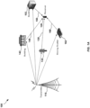
- FIG. 1A illustrates an example of a wireless communication system 100 that may exhibit time/frequency selective fading.
- the system 100 includes a transmitter 110 (e.g., a cell phone tower) and a receiver 120 (e.g., a cell phone).
- the scenario illustrated in FIG. 1 includes multiple pathways (multi-path) that the signal transmitted from the transmitter 100 travels through before arriving at the receiver 100.
- a first pathway 130 reflects through a tree 132
- second pathway 140 reflects off of a building 142
- a third pathway 150 reflects off of a second building 152.
- a fourth pathway 160 reflects off of a moving car 162.
- each of the pathways 130, 140, 150 and 160 travels a different distance, and is attenuated or faded at a different level and at a different frequency, when conventionally configured the receiver 120 may drop a call or at least suffer low throughput due to destructive interference of the multi-path signals.
- the transceiver 200 could, for example, operate in accordance with established protocols for time-division multiple access (TDMA), code-division multiple access (CDMA) or orthogonal frequency-division multiple access (OFDM) systems.
- TDMA time-division multiple access
- CDMA code-division multiple access
- OFDM orthogonal frequency-division multiple access
- the multipath communication channel 210 between a transmitter 204 and a receiver 208 is represented by a one-dimensional model.
- channel distortion is characterized using a one-dimensional representation of the impulse response of the communication channel.
- the transceiver 200 may include a one-dimensional equalizer 220 configured to at least partially remove this estimated channel distortion from the one-dimensional output data stream 230 produced by the receiver 208.
- one-dimensional channel model presents a number of fundamental problems.
- the one-dimensional channel models employed in existing communication systems are non-stationary; that is, the symbol-distorting influence of the communication channel changes from symbol to symbol.
- the channel state information appears random and much of it is estimated by interpolating between channel measurements taken at specific points, thus rendering the information inherently inaccurate.
- MIMO multi-antenna
- the received signal is a superposition of reflected copies of the transmitted signal, where each copy is delayed by the path delay ⁇ , frequency shifted by the Doppler shift v and weighted by the time-independent delay-Doppler impulse response h ( ⁇ ,v ) for that ⁇ and v.
- FIG. 2A shows the time-varying impulse response for an accelerating reflector in the ( ⁇ , t) coordinate system
- FIG. 2B shows the same channel represented as a time invariant impulse response in the ( ⁇ ,v) coordinate system.
- the disclosed modulation scheme contemplates an appropriate choice of orthogonal basis functions that render the effects of this channel to become truly time-independent in the domain defined by those basis functions.
- the proposed scheme has the following high level outline.
- Eq. ( 8 ) One important point of Eq. ( 8 ) is that the operator ⁇ h ( ⁇ ) can be compactly parametrized by a two dimensional function h( ⁇ ,v), providing an efficient, time-independent description of the channel. Typical channel delay spreads and Doppler spreads are a very small fraction of the symbol duration and subcarrier spacing of multicarrier systems.
- Equation ( 2 ) and ( 8 ) may be characterized as a Heisenberg representation. In this regard it may be shown that every linear operator (eq. ( 8 )) can be parameterized by some impulse response as in equation ( 2 ).
- the time variation of the channel introduces significant difficulties in wireless communications related to channel acquisition, tracking, equalization and transmission of channel state information (CSI) to the transmit side for beamforming and MIMO processing.
- CSI channel state information
- We herein develop a modulation domain based on a set of orthonormal basis functions over which we can transmit the information symbols, and over which the information symbols experience a static, time invariant, two dimensional channel for the duration of the packet or burst transmission.
- the channel coherence time is increased by orders of magnitude and the issues associated with channel fading in the time or frequency domain in SISO or MIMO systems are significantly reduced.
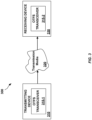
- FIG. 3 is a block diagram of components of an exemplary OTFS communication system 300.
- the system 300 includes a transmitter 310 and a receiver 330.
- the transmitting device 310 and the receiving device 330 include first and second OTFS transceivers 315-1 and 315-2, respectively.
- the OTFS transceivers 315-1 and 315-2 communicate, either unidirectionally or bidirectionally, via communication channel 320 in the manner described herein.
- the system 300 may comprise a wireless communication system, in other embodiments the communication channel may comprise a wired communication channel such as, for example, a communication channel within a fiber optic or coaxial cable.
- the communication channel 320 may include multiple pathways and be characterized by time/frequency selective fading.
- the components of the OTFS transceiver may be implemented in hardware, software, or a combination thereof.
- the processing units may be implemented within one or more application specific integrated circuits (ASICs), digital signal processors (DSPs), digital signal processing devices (DSPDs), programmable logic devices (PLDs), field programmable gate arrays (FPGAs), processors, controllers, micro-controllers, microprocessors, other electronic units designed to perform the functions described above, and/or a combination thereof.
- ASICs application specific integrated circuits
- DSPs digital signal processors
- DSPDs digital signal processing devices
- PLDs programmable logic devices
- FPGAs field programmable gate arrays
- processors controllers, micro-controllers, microprocessors, other electronic units designed to perform the functions described above, and/or a combination thereof.
- FIG. 3B there is provided a pictorial view of the two transformations that constitute an exemplary form of OTFS modulation. It shows at a high level the signal processing steps that are required at a transmitter, such as the transmitter 310, and a receiver, such as the receiver 330. It also includes the parameters that define each step, which will become apparent as we further expose each step. Further, FIG. 3C shows a block diagram of the different processing stages at the transmitter and receiver and establishes the notation that will be used for the various signals.
- x ⁇ X g tr : g tr t ⁇ H ⁇ ⁇ X ⁇ y t ⁇ H
- ⁇ X ( ⁇ ) the "discrete" Heisenberg operator, parameterized by discrete values X[n,m].
- the sampling rate in the time-frequency domain is related to the bandwidth and time duration of the pulse g tr (t); namely, its time-frequency localization.
- the time spacing In order for the orthogonality condition of ( 10 ) to hold for a frequency spacing ⁇ f, the time spacing must be T ⁇ 1 / ⁇ f .
- Proposition 1 Let two Heisenberg transforms as defined by Eqs. ( 8 ), ( 2 ) be parametrized by impulse responses h 1 ( ⁇ ,v), h 2 ( ⁇ ,v) and be applied in cascade to a waveform g(t) ⁇ .
- This result can be considered an extension of the single carrier modulation case, where the received signal through a time invariant channel is given by the convolution of the QAM symbols with a composite pulse, that pulse being the convolution of the transmitter pulse and the channel impulse response.
- Typical communication system design generally requires that the receiver perform a matched filtering operation, taking the inner product of the received waveform with the transmitter pulse, appropriately delayed or otherwise distorted by the channel.
- a matched filtering operation is typically performed with respect to each one of them.
- FIG. 4 provides a conceptual view of this processing.
- On the transmitter we modulate a set of M subcarriers for each symbol we transmit, while on the receiver we perform matched filtering on each of those subcarrier pulses.
- the receiver pulse g r (t) is in many cases identical to the transmitter pulse, but we keep the separate notation to cover some cases where it is not (most notably in OFDM where the CP samples have to be discarded).
- the sufficient statistics for symbol detection are obtained by matched filtering with the channel-distorted, information-carrying pulses (assuming that the additive noise is white and Gaussian).
- the channel distorted version of each subcarrier signal is only a scalar version of the transmitted signal, allowing for a matched filter design that is independent of the channel and uses the original transmitted subcarrier pulse. We will make these statements more precise shortly and examine the required conditions for this to be true.
- this matched filtering may be implemented in the digital domain using an FFT or a polyphase transform for OFDM and MCFB respectively.
- FFT Fast Fourier transform
- MCFB Polyphase transform
- the ambiguity function is related to the inverse of the Heisenberg transform, namely the Wigner transform.
- V( ⁇ ,v) A g r ,v ( ⁇ ,v).
- the first term on the right hand side is the matched filter output to the (noiseless) input comprising of a superposition of delayed and modulated versions of the transmit pulse.
- this term can be expressed as the twisted convolution of the two dimensional impulse response f( ⁇ ,v) with the cross-ambiguity function (or two dimensional cross correlation) of the transmit and receive pulses.
- the matched filter output at any time and frequency point ( ⁇ ,v) is given by the delay-Doppler impulse response of the channel twist-convolved with the impulse response of the modulation operator twist-convolved with the cross-ambiguity (or two dimensional cross correlation) function of the transmit and receive pulses.
- Eq. ( 30 ) is a fundamental equation that describes the channel behavior in the time-frequency domain. It is the basis for understanding the nature of the channel and its variations along the time and frequency dimensions.
- Example 3 (OFDM modulation).
- Example 4 (MCFB modulation).
- g(t) g(t).
- T is much larger than the support of the channel in the time dimension, then each subchannel sees a flat channel and the bi-orthogonality property holds approximately.
- time-frequency response H[n, m] in ( 30 ) is related to the channel delay-Doppler response h ( ⁇ , v) by an expression that resembles a Fourier transform.
- the transform is two dimensional (along delay and Doppler) and (ii) the exponentials defining the transforms for the two dimensions have opposing signs.
- Eq. ( 30 ) points in the direction of using complex exponentials as basis functions on which to modulate the information symbols; and only transmit on the time-frequency domain the superposition of those modulated complex exponential bases.
- this approach exploits Fourier transform properties and effectively translates a multiplicative channel in one Fourier domain to a convolution channel in the other Fourier domain.
- the resulting x ( ⁇ ,v) is periodic with periods (1 / ⁇ f, 1 /T) .
- This transform defines a new two dimensional plane, which we will call the delay-Doppler plane, and which can represent a max delay of 1 / ⁇ f and a max Doppler of 1 / T.
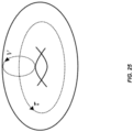
- a one dimensional periodic function is also called a function on a circle, while a 2D periodic function is called a function on a torus (or donut).
- x( ⁇ , v) is defined on a torus Z with circumferences (dimensions) (1 / ⁇ f, 1 / T).
- the points on the reciprocal lattice have the property of making the exponent in ( 34 ), an integer multiple of 2 ⁇ .
- x p [ m,n] is also periodic with period [M,N] or, equivalently, it is defined on the discrete torus Z 0 ⁇ .
- the SFFT(X[n, m]) is a linear transformation from C Z 0 ⁇ C Z 0 ⁇ .
- the SDFT is termed “discrete” because it represents a signal using a discrete set of exponentials, while the SFFT is called “finite” because it represents a signal using a finite set of exponentials.
- the first equation in ( 45 ) describes the OTFS transform, which combines an inverse symplectic transform with a windowing operation.
- the second equation describes the transmission of the modulation symbols X [ n, m] via a Heisenberg transform of g tr (t) parameterized by X[n, m]. More explicit formulas for the modulation steps are given by Equations ( 42 ) and ( 11 ).
- the first step of the demodulation operation can be interpreted as a matched filtering operation on the time-frequency domain as we discussed earlier.
- the second step is there to ensure that the input to the SFFT is a periodic sequence. If the trivial window is used, this step can be skipped.
- the discrete OTFS modulation defined above points to efficient implementation via discrete-and-periodic FFT type processing. However, it potentially does not provide insight into the time and bandwidth resolution of these operations in the context of two dimensional Fourier sampling theory.
- Continuous OTFS modulation Consider a two dimensional periodic function x( ⁇ , v) with period [ 1 / ⁇ f, 1 / T] that we wish to transmit. The choice of the period may seem arbitrary at this point, but the rationale for its choice will become apparent after the discussion below. Further, assume a multicarrier modulation system defined by
- the first equation describes the inverse discrete time-frequency symplectic Fourier transform [c.f. Eq. ( 36 )] and the windowing function, while the second equation describes the transmission of the modulation symbols via a Heisenberg transform [c.f. Eq. ( 11 )].
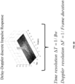
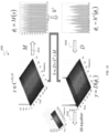
- FIG. 5A illustratively represents operations involved in OTFS-based communication, including the transformation of the time-frequency plane to the Doppler-delay plane.
- FIGS. 5A and 5B indicates relationships between sampling rate, delay resolution and time resolution.
- a Heisenberg transform translates a time-varying convolution channel in the waveform domain to an orthogonal but still time varying channel in the time frequency domain.
- a SFFT transform translates the time-varying channel in the time-frequency domain to a time invariant one in the delay-Doppler domain.
- the Doppler resolution is 1 / T f and the delay resolution is 1 / BW, with the Doppler and delay resolutions being mutually decoupled.
- the choice of window can provide a tradeoff between main lobe width (resolution) and side lobe suppression, as in classical spectral analysis.
- FIG. 5C an illustration is provided of signaling between various domains in an OTFS communication system. Specifically, FIG.5C illustrates signaling over: the (i) actual physical channel with a signaling waveform, (ii) the time-frequency domain, and (iii) the delay-Doppler domain.
- FIG. 5D illustrates exemplary notations used in denoting signals present at various stages of processing (e.g., encoding, modulation, decoding, demodulation) in an OTFS transmitter and receiver.
- Proposition 3 Consider a set of NM QAM information symbols arranged in a 2D periodic sequence x [ l,k] with period [M,N]. The sequence x[k,l] undergoes the following transformations:
- the window w( ⁇ ,v) is circularly convolved with a slightly modified version of the channel impulse response e -j2 ⁇ v ⁇ h ( ⁇ ,v) (by a complex exponential) as can be seen in the equation.
- W n m W tr n m W r n m
- the system can be designed with a window function aimed at randomizing the phases of the transmitted symbols. This randomization may be more important for pilot symbols than data carrying symbols. For example, if neighboring cells use different window functions, the problem of pilot contamination is avoided.
- a straightforward way to perform channel estimation entails transmitting a soudning OTFS frame containing a discrete delta function in the OTFS domain or, equivalently, a set of unmodulated carriers in the time frequency domain.
- the carriers may be modulated with known, say BPSK, symbols which are removed at the receiver, as is common in many OFDM systems.
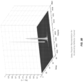
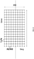
- FIG. 6 shows a discrete impulse 610 in the OTFS domain which may be used for purposes of channel estimation, e.g., as a form of pilot signal.
- the remainder of MXN delay-Doppler plane includes information symbols 620 arranged in a grid.
- MxN could be, for example, 1024X256 or 512x16.
- a series of clear regions 630 or zero symbols occupy positions proximate the discrete impulse 610.
- the delay-Doppler plane may be alternatively characterized herein as the "OTFS information domain" or the "delay-Doppler frame.”
- each UE can have its own channel estimation subframe positioned in different parts of the OTFS frame.
- channel estimation symbols are limited to a small part of the OTFS frame, they actually sound the whole time-frequency domain via the corresponding two-dimensional time-frequency basis functions associated with these symbols.
- a different approach to channel estimation is to devote pilot symbols on a subgrid in the time-frequency domain.
- the key question in this approach is the determination of the density of pilots that is sufficient for channel estimation without introducing aliasing. Assume that the pilots occupy the subgrid (n 0 T, m 0 ⁇ f) for some integers n 0 , m 0 . Recall that for this grid the SDFT will be periodic with period (1 / n 0 T, 1 / m 0 ⁇ f ).
- FIGS. 7A and 7B illustrates a pair of different exemplary basis functions capable of being used in OTFS communiations.
- a small subframe or resource block in the OTFS domain will be transmitted over the whole time-frequency frame via two-dimensional basis functions and will experience the average channel response.
- FIGS. 7A and 7B illustrate this point by showing two different basis functions belonging to different users. Because of this, there is no compromise on channel resolution for each user, regardless of the resource block or subframe size.
- FIGS. 7C and 7D collectively illustrate two-dimensional spreading with respect to both time and frequency in an OTFS communciation system.
- one or more QAM symbols 710 may be placed within the two-dimensional information domain or, equivalently, the two-dimensional delay-Doppler domain.
- Each QAM symbol within the information domain multiples a two-dimensional (i.e., time and freqeuncy domain) basis function 720.
- the trasnmitted signal is comprised of a set of QAM symbols spread across both time and frequency by a correspodning set of two-dimensional basis functions which are mutually orthogonal with respect to both time and frequency. That is, the transmitted signal is a superposition of multiple QAM signals weighting the two-dimensional basis functions. This superposition may be termed a "wave aggregate".
- FIG. 7E illustrates members of one potential set of such mutually orthogonal two-dimensional basis functions.
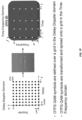
- FIG. 7F illustrates a process of transforming and spreading OTFS data symbols (e.g., QAM symbols) defined on a grid in a delay-Doppler domain onto a grid in the time-frequency domain.
- the data symbol at each frame location is used to modulate a unique 2D basis wave function selected from a set of mutually orthogonal 2D basis wave functions operating over a 2D OTFS time-frequency frame.
- the transformation involves spreading each data symbol, in a lossless and invertible manner, throughout substantially all of the 2D OTFS time-frequency frame. In this way the transforamtion creates a 2D OTFS time-frequency frame based wave aggregate.
- FIG. 7G illustrates the spreading of an OTFS QAM symbol defined in the delay-Doppler domain onto a set of grid points in the time-freqeuncy domain as a result of a two-dimensional OTFS transform using a two-dimensional basis function.
- each OTFS QAM symbol may be represented as a multiplication of two linear phases.
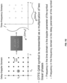
- FIG. 8 illustrates this for a three user case. As shown in FIG. 8 , a first user (U1) occupies the whole frame length but only half the available subcarriers. A second user (U2) and a third user (U3) occupy the other half subcarriers, and divide the total length of the frame between them.
- each user employs a slightly different version of the OTFS modulation described.
- One difference is that each user i performs an SFFT on a subframe (N i ,M i ), N i ⁇ N, M i ⁇ M. This reduces the resolution of the channel, or in other words reduces the extent of the time-frequency plane in which each user will experience its channel variation. On the other side, this also gives the scheduler the opportunity to schedule users in parts of the time-frequency plane where their channel is best.
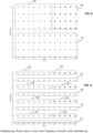
- FIG. 9 shows the same three users as in FIG. 8 , but interleaved on the subcarrier dimension.
- interleaving is possible in the time dimension as well, and/or in both dimensions.
- the degree of interleaving, or subsampling the grid per user is only limited by the spread of the channel that must be accommodated.
- OTFS can support such a system by assigning each user a different two-dimensional window function that is designed as a randomizer.
- the windows of different users are designed to be nearly orthogonal to each other and nearly orthogonal to time and frequency shifts.
- Each user then only transmits on one or a few basis functions and uses the window as a means to randomize interference and provide processing gain. This can result in a much simplified system that may be attractive for low cost, short burst type of IoT applications.
- a multi-antenna OTFS system can support multiple users transmitting on the same basis functions across the whole time-frequency frame. The users are separated by appropriate transmitter and receiver beamforming operations.
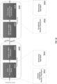
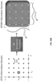
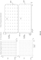
- FIG. 38 illustrates a multiple access scheme in which a first user (UE1) is allocated a first window 3810 and a second user (UE2) is allocated a second window 3820 in the time-frequency domain.
- UE1 first user
- UE2 second user
- the window 3820 in the time-frequency domain corresponding to UE2 is shifted in frequency.
- each of UE1 and UE2 are allocated half of the available subcarriers over the entire frame length.
- each of UE1 and UE2 use a sparser lattice than the original lattice and use every other point in the delay ( ⁇ ) domain.
- each of UE1 and UE2 are accorded only half of the resolution in the delay dimension but both UE1 and UE2 have full resolution in the Doppler dimension.
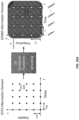
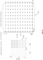
- both UE1 and UE2 cover the full span of both delay and Doppler Attention is now directed to FIG. 39 , which illustrate a multiple access scheme in which a first user (UE1), a second user (UE2) and a third user (UE3) are each allocated a window (3910, 3920, 3930) in the time-frequency domain.
- UE1 first user
- UE2 a second user
- UE3 third user
- Each of UE1, UE2 and UE3 use a sparser lattice than the original lattice and UE1 uses every other point in the delay ( ⁇ ) domain.
- UE2 and UE3 use every other point in both the delay ( ⁇ ) and Doppler (v) domains
- UE1 has half of the resolution in the delay dimension and full resolution in the Doppler dimension.
- Both UE2 and UE3 have half of the resolution in both delay and Doppler dimensions.
- Each of UE1, UE2 and UE3 cover the full span of both delay and Doppler.
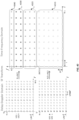
- FIG. 40 an illustration is provided of a multiple access scheme in which a first user (UE1) is allocated a split window (4010A, 4010B) in the time-frequency domain.
- windows 4020, 4030 in the time-frequency domain for a second user (UE2) and a third user (UE3) are located between the portions of the split window associated with UE1.
- the windows 4020, 4030 for UE2 and UE3 are shifted in frequency, and the window 4030 for UE3 is also shifted in time.
- each of UE1, UE2 and UE3 use a sparser lattice than the original lattice.
- UE1 uses every other point in the delay ( ⁇ ) domain.
- UE2 and UE3 use every other point in both the delay ( ⁇ ) and Doppler (v) domains. It is notes that the lines above M/2 are copies of lines 0 to (M/4 - 1).
- each UE will experience a different channel in each of these embodiments since they will use different frequencies in each embodiment.
- FIG. 41 an illustration is provided of a multiple access scheme in which each of a first user (UE1) and a second user (UE2) utilize different halves of the original lattice. Specifically, UE1 uses the left half 4110 of the original lattice but does not allocate any power to resources in the right half 4120 of the original lattice. Similarly, UE2 uses the right half 4120 of the original lattice but does not allocate any power to resources in the left half 4110 of the original lattice. As shown, the time-frequency windows (shown as a single window 4130) for both UE1 and UE2 are contiguous on the full lattice.
- both UE1 and UE2 have full resolution in both the delay and Doppler dimensions. Similarly, both UE1 and UE2 cover the full Doppler span and half of the delay span. When this approach is employed on the uplink, the receiver experiences a different channel from each of UE1 and UE2.
- FIG. 42 illustrates an alternative multiple access scheme which is similar to that depicted in FIG. 41 .
- UE1 uses the left half 4210 of the original lattice but does not allocate any power to resources in the right half 4220 of the original lattice.
- UE2 uses the right bottom quarter 4230 of the original lattice but does not allocate any power to resources in the remaining 3 ⁇ 4 of the original lattice.
- UE3 uses the right top quarter of the original lattice but does not allocate any power to resources in the remaining 3 ⁇ 4 of the original lattice.
- the time-frequency windows shown as a single window 4240 for UE1, UE2 and UE3 are the same and contiguous.
- UE1 covers the full Doppler span and half of the delay span.
- UE2 and UE3 cover half of the Doppler span and half of the delay span. Again, when this approach is employed on the uplink the receiver will experience a different channel from each of UE1, UE2 and UE3.
- FIG. 43 illustrates yet another multiple access scheme in which each of four UEs are allocated windows (4310, 4320, 4330, 4340) in the time-frequency domain.
- FIG. 44 illustrates a multiple access scheme for a set of five UEs in which three of the UEs, i.e., UE2, UE3 and UE4, are allocated contiguous windows (4410, 4420, 4430) in the time-frequency domain. As shown in FIG. 44 , the two remaining UEs, i.e., UE1 and UE5, are allocated interleaved subcarriers within a fourth window 4440 in the time-frequency domain.
- embodiments of Orthogonal Time Frequency Space (OTFS) modulation are comprised of a cascade of two transformations.
- the first transformation maps the two dimensional plane where the information symbols reside (and which may be termed the delay-Doppler plane) to the time frequency plane.
- the second transformation transforms the time frequency domain to the waveform time domain where the transmitted signal is actually constructed. This transform can be thought of as a generalization of multicarrier modulation schemes.
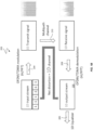
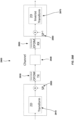
- FIG. 10 illustrates components of an exemplary OTFS transceiver 1000.
- the OTFS transceiver 1000 can be used as one or both of the exemplary OTFS transceivers 315 illustrated in the communication system 300 of FIG. 3 .
- the OTFS transceiver 1000 includes a transmitter module 1005 that includes a pre-equalizer 1010, an OTFS encoder 1020 and an OTFS modulator 1030.
- the OTFS transceiver 1000 also includes a receiver module 1055 that includes a post-equalizer 1080, an OTFS decoder 1070 and an OTFS demodulator 1060.
- the components of the OTFS transceiver may be implemented in hardware, software, or a combination thereof.
- the processing units may be implemented within one or more application specific integrated circuits (ASICs), digital signal processors (DSPs), digital signal processing devices (DSPDs), programmable logic devices (PLDs), field programmable gate arrays (FPGAs), processors, controllers, micro-controllers, microprocessors, other electronic units designed to perform the functions described above, and/or a combination thereof.
- ASICs application specific integrated circuits
- DSPs digital signal processors
- DSPDs digital signal processing devices
- PLDs programmable logic devices
- FPGAs field programmable gate arrays
- processors controllers, micro-controllers, microprocessors, other electronic units designed to perform the functions described above, and/or a combination thereof.
- the disclosed OTFS methods will be described in view of the various components of the transceiver 1000.
- a method of OTFS communication involves transmitting at least one frame of data ([D]) from the transmitting device 310 to the receiving device 330 through the communication channel 320, such frame of data comprising a matrix of up to N 2 data elements, N being greater than 1.
- the method comprises convolving, within the OTFS transceiver 315-1, the data elements of the data frame so that the value of each data element, when transmitted, is spread over a plurality of wireless waveforms, each waveform having a characteristic frequency, and each waveform carrying the convolved results from a plurality of said data elements from the data frame [D].
- the OTFS transceiver 315-2 receives and deconvolves these wireless waveforms thereby reconstructing a replica of said at least one frame of data [D].
- the convolution process is such that an arbitrary data element of an arbitrary frame of data ([D]) cannot be guaranteed to be reconstructed with full accuracy until substantially all of these wireless waveforms have been transmitted and received.
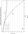
- FIG. 11 illustrates a comparison of bit error rates (BER) predicted by a simulation of a TDMA system and an OTFS system. Both systems utilize a 16 QAM constellation. The simulation modeled a Doppler spread of 100Hz and a delay spread of 3 microsec. As can be seen from the graphs, the OTFS system offers much lower BER than the TDMA system for the same signal-to-noise ratio (SNR).
- SNR signal-to-noise ratio
- FIG. 12 is a flowchart representative of the operations performed by an OTFS transceiver 1200 which may be implemented as, for example, the OTFS transceiver 1000 ( FIG. 10 ).
- the OTFS transceiver 1200 includes a transmitter including a modulator 1210 and a receiver including a demodulator 1220 and two-dimensional equalizer 1230.
- a transmitter of the OTFS transceiver 1200 receives a two-dimensional symbol stream in the form of an N ⁇ N matrix of symbols, which may hereinafter be referred to as a TF matrix: x ⁇ C N ⁇ N
- the modulator 1210 functions as an orthogonal map disposed to transform the two-dimensional TF matrix to the following transmitted waveform:
- the demodulator 1220 transforms the received waveform to a two-dimensional TF matrix in accordance with an orthogonal map in order to generate an output stream 1420:
- the OTFS transceiver 1200 may be characterized by a number of variable parameters including, for example, delay resolution (i.e., digital time "tick” or clock increment) , Doppler resolution, processing gain factor (block size) and orthonormal basis function.
- delay resolution i.e., digital time "tick” or clock increment
- Doppler resolution i.e., Doppler resolution
- processing gain factor block size
- the modulator 1210 takes a TF matrix x ⁇ C N ⁇ N and transforms it into a pulse waveform.
- L t and M w are respectively representative of cyclic time and frequency shifts and may be represented as:
- the equalizer 1230 may be implemented as a two-dimensional decision feedback equalizer configured to perform a least means square (LMS) equalization procedure such that: y ⁇ x ⁇
- LMS least means square
- OTFS pilot symbols may be used to configure a 2D OTFS equalizer.
- one or more pilot symbols may be associated with one or more defined pilot symbol locations within a delay-Doppler frame.
- a plurality of data symbols may also be included within the delay-Doppler frame.
- the pilot and data symbols may then be transformed, by a transmitter processor, into a 2D OTFS time-frequency frame based wave aggregate. In this manner the one or more pilot symbols are spread, in a lossless manner, throughout substantially all of the 2D OTFS time-frequency frame based wave aggregate.
- the transmitted frequency filtered portions of the 2D OTFS time-frequency frame based wave aggregate are channel distorted according to the delay and Doppler characteristics of said channel.
- the receiver since the receiver is aware of the location of the pilot symbol is located within the delay-Doppler frame, it may configure the 2D equalizer based upon this knowledge the manner in which the pilot symbol is distorted during transit through the channel.
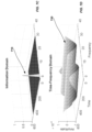
- time-frequency response characteristics 1610 of an exemplary 2D OTFS equalizer By configuring the 2D equalizer to implement an inverse of the known delay-Doppler impulse response, distortions within the channel-distorted replica of a 2D OTFS delay Doppler frame within a demodulator output stream 1620 may be removed. The result is a frame comprised of replica data symbols 1640 corresponding to very high fidelity replicas of the original data symbols.
- the 2D OTFS equalizer is capable of operation without use of OFDM cyclic prefixes or use of OFDM subcarrier or symbol time localized pilot symbols.
- FIGS. 17A-17D depict an OTFS transmitter 102 and receiver 104 to which reference will be made in describing the transmission and reception of OTFS waveforms. More specifically, FIGS. 17B-17D illustrate the transmission and reception of OTFS waveforms relative to a time-frequency transmitter grid or series of bins and a corresponding time-frequency receiver grid or series of bins. As will be discussed below, the receiver 104 will generally operate with respect to a time-frequency receive grid of a finer mesh than that of the time-frequency transmit grid associated with the transmitter 102.
- the transmitter 102 and receiver 104 are separated by an impaired wireless data channel 100 including one or more reflectors 106.
- the reflectors 106 may reflect or otherwise impair waveforms (112, 114a, 114b) as they travel through the data channel 100.
- These reflectors may be inherently represented by the two-dimensional (2D) channel state of the channel 100 (see, e.g., the finite channel h eqv,f of FIG. 18 ).
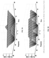
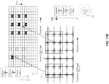
- FIGS. 18A and 18B illustratively represent OTFS communication over a communication channel characterized by a two-dimensional delay-Doppler impulse response.
- the set of bar diagrams of FIGS. 18A and 18B may represent a two-dimensional impulse response realizing a finite modulation equivalent channel, a transmitted information vector x comprised of OTFS QAM symbols and a received information vector y comprised of received OTFS symbols.
- the various QAM symbols in the original 2D OTFS delay-Doppler frame end up being smeared or otherwise distorted over multiple bins.
- FIGS. 18A and 18B One advantage of embodiments of OTFS communication systems suggested by FIGS.
- the two-dimensional channel model is stationary and all symbols experience the same distortion.
- the OTFS channel model is non-fading and every symbol may be spread across the full duration and bandwidth and experiences all diversity branches of the channel.
- the deterministic nature of the two-dimensional OTFS channel reflects the geometry of the channel reflectors (distance and velocity). This enables a 2D OTFS equalizer to remove distortions from this smeared signals and thereby produce an equalized 2D OTFS delay-Doppler frame (not shown) having much greater fidelity to the transmitted OTFS frame.
- the transmitter 102 includes a transmitter processor 102p to package input data into at least one NxM array of data symbols. An encoding process is then used to transmit this array of data symbols in accordance with the OTFS modulation techniques described herein.
- the transmitted OTFS waveforms are received by a receiver 104, which includes a receiver processor 104p.
- the receiver processor 104p utilizes information pertaining to the 2D state of the channel 100 to enable these OTFS waveforms to be decoded and recover the transmitted data symbols.
- the receiver processor 104p may use an inverse of the OTFS encoding process to decode and extract this plurality of data symbols. Alternatively the correction of signals for data channel impairments can be done after the receiver has decoded and extracted the plurality of data symbols.
- OTFS data transmission may be implemented by transforming the input NxM array of data symbols into at least one block or array of filtered OFDM symbols. This can be done, for example, using one dimensional Fourier transforms and a filtering process or algorithm. This block or array of filtered OFDM symbols may then be transformed into at least one block or array of OTFS symbols using various types of two dimensional Fourier transforms. These results will typically be stored in transmitter memory 102m. The stored results can then be communicated over wireless frequency sub-bands by various methods. For example, in one embodiment a transmitter 102c that employs a series of M narrow-band filter banks may be utilized. In this implementation the transmitter 102c produces a series of M mutually orthogonal waveforms transmitted over at least N time intervals.
- gaps or "guard bands" in both time and frequency may be imposed to minimize the possibility of inadvertent cross talk between the various narrow-band filters and time intervals prior to transmission.
- any such gaps or guard bands can be increased or decreased or set to zero as situations warrant.
- the OTFS encoding process may encode the NxM array of data symbols onto a manifold compatible with symplectic analysis.
- the symbols may be distributed over a column time axis of length T and row frequency axis of length F, thereby producing at least one information manifold for storage in transmitter memory 102m.
- the information manifold effectively holds information corresponding to the input data symbols in a form enabling them to be subsequently transformed in accordance with the desired OTFS transformation operation such as, for example, a symplectic 2D Fourier transform, a discrete symplectic 2D Fourier transform, a finite symplectic Fourier transform, and the like.
- the data symbols may also be spread prior to being held within an information manifold.
- the OTFS processor 102p may then transform the information manifold according to a 2D symplectic Fourier transform.
- This transformation may be effected using any of the previously discussed symplectic 2D Fourier transforms, discrete symplectic 2D Fourier transforms, and finite symplectic Fourier transforms.
- This operation produces at least one 2D Fourier transformed information manifold, which may be stored in transmitter memory 102m.
- the OTFS transmitter 102c will typically transmit this at least one 2D Fourier transformed information manifold as a series of "M" simultaneous narrow band waveforms, each series over consecutive time intervals, until the entire 2D Fourier transformed information manifold has been transmitted.
- the transmitter processor 102p can operate, often on a one column at a time basis, over all frequencies and times of this 2D Fourier transformed information manifold.
- Those frequencies in the column slice of this 2D Fourier transformed information manifold e.g.
- frequencies corresponding to this transmitting time slice may then be passed through a bank of at least M different, nonoverlapping, narrow-band frequency filters. This produces M mutually orthogonal waveforms.
- the processor 102p can then cause these resulting filtered waveforms to be transmitted, over different transmitted time intervals (e.g. one column at a time), as a plurality of at least M mutually orthogonal waveforms until an entire 2D Fourier transformed information manifold has been transmitted.
- gaps or "guard bands" in both time and frequency may be imposed to minimize the possibility of inadvertent cross talk between the various narrow-band filters and time intervals prior to transmission.
- any such gaps or guard bands can be increased or decreased or set to zero as situations warrant.
- Each OTFS receiver 104 may then receive a channel-convoluted version of the 2D Fourier transformed information manifold transmitted by the transmitter 102. Due to distortions introduced by the channel 100, the M narrow band waveforms originally transmitted at M original frequencies may now comprise more than M narrow band waveforms at a different range of frequencies. Moreover, due to transmitted OTFS waveforms impinging various reflectors 106, the originally transmitted signals and reflections thereof may be received at different times. As a consequence, each receiver 104 will generally supersample or oversample the various received waveforms on a time-frequency grid having a finer mesh than that associated with the transmitter 102. This oversampling process is represented by FIGS. 17B-17D , which depict a receiver time-frequency grid having smaller time and frequency increments than the transmitter OTFS grid.
- Each OTFS receiver 104 operates to receive the transmitted 2D Fourier transformed information manifold over time slices having durations that are generally less than or equal to the transmission time intervals employed by the transmitter 102.
- the receiver 104 analyzes the received waveforms using a receiving bank of at least M different, non-overlapping, narrow-band frequency filters. The receiver will then generally store the resoling approximation (channel convoluted version) of the originally transmitted 2D Fourier transformed information manifold in receiver memory 104m.
- the receiver 104 then corrects for the convolution effect of the channel 100 in order to facilitate recovery of an estimate of the originally transmitted data symbols.
- the receiver 104 may effect these corrections in a number of ways.
- the receiver 104 may use an inverse of the 2D symplectic Fourier transform used by the transmitter 102 to transform the received waveforms into an initial approximation of the information manifold originally transmitted.
- the receiver 104 may first use information pertaining to the 2D channel state to correct the channel-convoluted approximation of the transmitted 2D Fourier transformed information manifold (stored in receiver memory). Following this correction the receiver 104 may then use the inverse of the 2D symplectic Fourier transform employed at the transmitter 102 to generate a received information manifold and subsequently extract estimated data symbols.
- the OTFS methods described herein inherently spread any given data symbol over the entire time-frequency plane associated with a transmitter, in some embodiments it may be useful to implement an additional spreading operation to insure that the transmitted data symbols are uniformly distributed.
- This spreading operation may be carried out by the transmitter processor 102p either prior to or after encoding the input NxM 2D array of data symbols onto the symplectic analysis compatible manifold.
- a number of spreading functions such as, for example, a 2D chirp operation, may be used for this purpose.
- the receiver 104 will utilize an inverse of this spreading operation in order to decode and extract the data symbols from the various received information manifolds.
- FIG. 19 illustrates transmission of a 2D Fourier transformed information manifold represented by an NxM structure over M frequency bands during N time periods of duration T ⁇ .
- each of the M frequency bands is represented by a given row and each different time period is represented by a given column.
- the OTFS transmitter is configured to transmit OTFS signals during without guard intervals over the allocated bandwidth, which encompasses the M frequency bands.
- the bandwidth ( ⁇ 0 ) of each of the M frequency bands is, is 1/T ⁇ .
- M must have a bandwidth no larger than 1/T ⁇ and the bandwidth used by all M filtered OTFS frequency bands cannot exceed M/T, where T is the total amount of time used to transmit all N columns of the 2D Fourier transformed information manifold.
- the various 2D Fourier transformed information manifolds may be received using banks of different, nonoverlapping, narrow-band frequency filters that are generally similar to those used by the transmitter 102.
- the receiver time slices and receiving banks of filters will generally operate with finer granularity; that is, the receiver will typically operate over smaller frequency bandwidths, and shorter time slices, but over a typically broader total range of frequencies and times.
- the receiver bin structure will preferably oversample the corresponding transmitting time slices and transmitting banks of different, non-overlapping, narrow-band frequency filters previously used by the transmitter.
- the OTFS transmitter will typically transmit the resulting filtered waveforms (in this example over all rows and successive columns), until the entire 2D Fourier transformed information manifold has been transmitted.
- the transmitter can either transmit the successive columns (time slices) continuously and contiguously - that is without any time gaps in-between, as more of a series of continuous longer duration waveforms, or alternatively the transmitter can put some time spacing between the various successive columns, thus creating a more obvious series of waveform bursts.
- the transmitter can transmit the resulting filtered waveforms as either: 1) a plurality of at least M simultaneously transmitted mutually orthogonal waveforms over either different consecutive transmitted time intervals; or 2) a plurality OTFS data or OTFS pilot bursts comprising at least M simultaneously transmitted mutually orthogonal waveform bursts over different transmitted intervals separated by at least one spacer time interval.
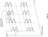
- FIG. 20 shows an example of the M filtered OTFS frequency bands being simultaneously transmitted according to various smaller time slices T ⁇ .
- the repeating curved shapes show the center frequency for each filtered band according to g ( t ⁇ e jk ⁇ 0 ).
- the OTFS receiver will use oversampling, and thus use finer granularity bins that nonetheless may extend over a broader range of times and frequencies so as to catch signals with high degrees of delay or Doppler frequency shift.
- the non-overlapping, narrow-band frequency filters used at the transmitter may be configured to pass frequencies from the various 2D Fourier transformed Information manifolds that are proportional to a filter function g ( t ⁇ e jk ⁇ 0 ) , where j is the square root of -1, t corresponds to a given time slice of duration T ⁇ chosen from a 2D Fourier transformed information manifold, and k corresponds to a given row position in a given 2D Fourier transformed information manifold, where k varies between 1 and M.
- the various 2D Fourier transformed information manifolds can have overall dimensions NT ⁇ according to a time axis and M/T according to a frequency axis, and each "cell" or “bin” in the various 2D Fourier transformed information manifold may have overall dimensions proportional to T ⁇ according to a time axis and 1/T according to a frequency axis.
- FIG. 21 provides another example of OTFS waveforms being transmitted according to various smaller time slices T ⁇ .
- T ⁇ time slices
- the amplitude or extent of modulation of the various waveforms as a function of time is also shown.
- grid, bin, or lattice locations of the originally transmitted OTFS waveforms may be distinguished by determining time and frequency related parameters of the received waveforms.
- the "k ⁇ 0 " term may enable the receiver to distinguish any given incoming OTFS waveform by its originating "column" location "t".
- the receiver should also be able to determine the bin (grid, lattice) location of the various received waveforms by determining both the t (time related) and k (frequency related) values of the various received waveforms. These values may then be used during subsequent deconvolution of the received signals.
- an additional time and/or frequency varying modulation scheme may also be imposed on the OTFS signals, prior to transmission, to allow the OTFS receiver to further distinguish the bin (grid, lattice ) origin of the various received signals.
- either the information manifold or the 2D Fourier transformed information manifolds may be sampled and modulated using Dirac comb methods.
- the Dirac combs utilized by these methods may be, for example, a periodic tempered distribution constructed from Dirac delta functions.
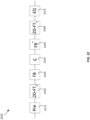
- FIG. 22 provides a block diagrammatic representation of an exemplary process 2200 of OTFS transmission and reception in accordance with the present disclosure.
- the process 2200 begins with the packaging of data for transmission and its optional precoding to correct for known channel impairments (stage 2210). This material is then processed by a 2D Fourier Transform (such as a symplectic Fourier transform, discrete symplectic Fourier transform, or finite symplectic Fourier transform) (stage 2220). Following this processing the results are then passed through a filter bank (FB) and transmitted over a series of time intervals T ⁇ (stage 2230).
- FB filter bank
- the transmitted wireless OTFS waveforms then pass through the communications or data channel (C), where they are subject to various distortions and signal impairments (stage 2240).
- the received waveforms are received according to a filter bank at various time intervals (stage 2250).
- the receiver filter bank (FB*) may be an oversampled filter bank (FB*) operating according to oversampled time durations that may be a fraction of the original time intervals T ⁇ . This oversampling enables the received signals to be better analyzed for channel caused time delays and frequency shifts at a high degree of resolution.
- stage 2260 the received material is analyzed by an inverse 2D Fourier Transform (2D-FT s ) (which again may be an inverse symplectic Fourier transform, inverse discrete symplectic Fourier transform, or inverse finite symplectic Fourier transform).
- 2D-FT s 2D Fourier Transform
- stage 2270 may precede stage 2260.
- Orrthogonal time frequency space is a novel modulation scheme capable of being implemeneted by communication transceivers that converts the dynamic one dimensional wireless medium into a static two dimensional local ISI channel by putting the time and frequency dimensions on an equal footing.
- OTFS transceiver relative to a conventional transceiver are the following:
- the OTFS transceiver establishes a virtual wire through a communiation medium, thus allowing the application of conventional wired DSP technologies in the wireless domain.
- Embodiments of the OTFS transceiver are based on principles from representation theory, generalizing constructions from classical Fourier theory. On the operational level, OTFS may be roughly characterized as an application of the two dimensional Fourier transform to a block of filtered OFDM symbols.
- OTFS is a true two dimensional time-frequency modulation, and may incorporate both two dimensional time-frequency filtering and two dimensional equalization techniques. In what follows we provide a formal mathematical development of the OTFS transceiver, focusing on a rigorous derivation of the two dimensional channel model.
- undersampled time-frequency lattice that is, a two dimensional lattice of density smaller or equal than 1.
- the undersampling condition is essential for perfect reconstruction, however, it seems to limit the delay-Doppler resolution of the channel acquisition.
- radar theory amounts to choosing an oversampled time frequency lattice of density greater or equal than 1 where the oversampling condition is essential for maximizing the delay-Doppler resolution of target measurement.
- the symplectic (two dimensional) Fourier transform intertwines between communication and radar lattices.
- the OTFS communication paradigm is to multiplex information symbols on an oversampled high resolution radar lattice and use the symplectic Fourier transform together with two dimensional filtering to convert back to communication coordinates. This allows OTFS to reap the benefits of both worlds - high resolution delay-Doppler channel state measurement without sacrificing spectral efficiency.
- the OTFS channel model may be thought of as a high resolution delay-Doppler radar image of the wireless medium.
- H L 2 (R) denote the vector space of "physical" waveforms defined on the time domain.
- the physics of the wireless medium is governed by the phenomena of multipath reflection, that is, the transmitted signal is propagating through the atmosphere and reflected from various objects in the surrounding. Some of the objects, possibly including the transmitter and the receiver, are moving at a non-zero velocity.
- the received signal is a superposition of time delays and Doppler shifts of the transmitted signal where the delay in time is caused by the excess distance transversed by the reflected waveform and the Doppler shift is caused by the relative velocity between the reflector and the transmitting and/or receiving antennas.
- the channel C is determined by the function h that depends on two variables ⁇ and v, referred to as delay and Doppler.
- this terminology is misleading since the action of h given by (0.1) is not a convolution action.
- the phenomena of fading corresponds to local attenuation in the energy profile of the received signal as measured over a specific dimension. It is customary to consider two kind of fadings: time selective fading and frequency selective fading. The first is caused by destructive superposition of Doppler shifts and the second is caused by destructive superposition of time delays. Since the wireless channel consists of combination of both time delays and Doppler shifts it exhibits both types of fading. Mitigating the fading phenomena is a significant motivation behind the development of the OTFS transceiver.
- Equation (0.1) the delay Doppler channel representation given in Equation (0.1) is the application of a fundamental mathematical transform, called the Heisenberg representation, transforming between functions on the delay Doppler plane V and linear operators on the signal space H .
- the wireless channel is an application of the Heisenberg representation to a specific function h on the delay Doppler plane.
- This higher level of abstraction establishes the map ⁇ as the fundamental object underlying wireless communication.
- the correspondence a ⁇ ⁇ ( a ) generalizes the classical correspondence between a stationary linear system and a one dimensional impulse response to the case of arbitrary time varying systems (also known as linear operators).
- the main property of the Heisenberg representation is that it translates between composition of linear operators and an operation of twisted convolution between the corresponding impulse responses.
- Equation (0.4) is key to the derivation of the two dimensional channel model - the characteristic property of the OTFS transceiver.
- the OTFS transceiver provides a mathematical transformation having the effect of converting the fading wireless channel into a stationary two dimensional convolution channel. We refer to this property as the two dimensional channel model.
- the OTFS transceiver may be characterized as a pair of linear transformations ( M , D ) where M is termed a modulation map and D is termed a demodulation map and is the inverse of M .
- M is termed a modulation map
- D is termed a demodulation map and is the inverse of M .
- the information bits are encoded as a complex valued function on V which periodic with respect to a lattice ⁇ ⁇ ⁇ V called the reciprocal communication lattice.
- the term "reciprocal” is used to suggest a type of duality relation between ⁇ ⁇ and a more conventional lattice A, called the primal communication lattice. If we denote by C( V ) ⁇ ⁇ the vector space of ⁇ ⁇ -periodic functions on V then the OTFS modulation is a linear transformation: M : C V ⁇ ⁇ ⁇ H .
- the demodulation map is a linear transformation acting in the opposite direction, namely: D : H ⁇ C V ⁇ ⁇ .
- Equations (0.7) and (0.8) encodes the precise manner of interaction between the OTFS transceiver and the wireless channel.
- the delay Doppler plane is equipped with an intrinsic geometric structure encoded by a symplectic form (also called symplectic inner product or symplectic pairing).
- C( V ) the vector space of complex valued functions on V .
- * the operation of linear convolution of functions on V .
- g ⁇ 2 ⁇ ⁇ ′ ⁇ V f ⁇ ′ g ⁇ ⁇ ⁇ ′ d ⁇ ′ , for every v ⁇ V .
- vol( ⁇ T, ⁇ ) ⁇ .
- ⁇ T, ⁇ the standard communication lattice.
- ⁇ ⁇ consists of all vectors in V such that their symplectic pairing with every vector in A is integral.
- ⁇ ⁇ is indeed a lattice.
- ⁇ ⁇ is the reciprocal lattice of A .
- vol ⁇ ⁇ 1 / vol ⁇ , which implies that A is undersampled if and only if ⁇ ⁇ is oversampled. This means that reciprocity interchanges between coarse (undersampled) lattices and fine (oversampled) lattices. Another attribute concerns how lattice inclusion behaves under reciprocity.
- C(A) the vector space of complex valued functions on the lattice.
- * the convolution operations between functions on ⁇ .
- Tori A torus Z is a two dimensional periodic domain that constitutes the geometric dual of a lattice ⁇ .
- An alternative, albeit less canonical, way to construct Z is to glue opposite faces of a fundamental domain of A.
- Z has the shape of a "donut" obtained by folding the plane V with respect to the lattice A.
- Z has the shape of a "donut" obtained by folding the plane V with respect to the lattice A.
- Z is the torus associated with A or sometimes also as the dual of A.
- a torus is the two dimensional counterpart of a circle, where the second is obtained by folding the line R with respect to a one dimensional lattice ZT ⁇ R.
- Example 1.3 (standard communication torus).
- Z T, ⁇ is the Cartesian product of two circles; one of diameter T ⁇ and the other of diameter 1/ T .
- Z T , ⁇ as the standard communication torus.
- Z 0 is a domain associated with a pair consisting of a lattice A ⁇ V and a sublattice ⁇ 0 ⁇ ⁇ .
- Example 1.4 The standard communication finite torus.
- ⁇ T, ⁇ Fix positive integers n,m ⁇ N ⁇ 1 .
- the finite torus Z T , ⁇ m , n is isomorphic to the Cartesian product of two cyclic groups; one of order n and the other of order m.
- Z T , ⁇ m , n as the standard communication finite torus.
- a function on Z 0 is naturally equivalent to a function f :
- Z 0 ⁇ as the reciprocal finite torus. Although different as sets, one can show that, in fact, Z 0 and Z 0 ⁇ are isomorphic as finite groups.
- Example 1.5 Consider the pair consisting of the standard communication lattice ⁇ T, ⁇ and the sublattice ( ⁇ T, ⁇ ) m,n ⁇ ⁇ T, ⁇ .
- the finite torus associated with ( ⁇ T, ⁇ ) n,m ⁇ ⁇ T, ⁇ is isomorphic to: Z 0 ; Z / Z n ⁇ Z / Z m .
- Z 0 and Z 0 ⁇ are isomorphic as finite groups as both groups are isomorphic to the Cartesian product (albeit in different order) of two cyclic groups, one of order n and the other of order m .
- the symplectic Fourier transform is a variant of the two dimensional Fourier transform that is associated with the symplectic form ⁇ .
- the interchanging property follows from a more fundamental property that concerns the operations of two dimensional translation and symplectic modulation.
- the discrete symplectic Fourier transform relates between functions of two discrete variables and functions of two continuos periodic variables.
- the formal definition assumes a choice of a lattice A ⁇ V .
- Equation (2.11) provides that taking the continuos Fourier transform of a function f and than periodizing with respect to translations by the reciprocal lattice ⁇ ⁇ is the same as first restricting f to the lattice A and then taking the discrete Fourier transform.
- the finite symplectic Fourier transform relates functions of two finite periodic variables.
- the formal definition assumes a pair consisting of a lattice A ⁇ V and a sublattice ⁇ 0 ⁇ A .
- ⁇ ⁇ and ⁇ 0 ⁇ be the corresponding reciprocal lattices.
- Equation (2.17) states that taking the discrete symplectic Fourier transform of a function f on a lattice A and than restricting to the reciprocal lattice ⁇ 0 ⁇ is the same as first periodizing f with respect to translations by the sublattice ⁇ 0 and than taking the finite Fourier transform.
- Example 2.7 Consider the standard communication lattice ⁇ T, ⁇ and the sublattice ( ⁇ T, ⁇ ) n,m . We have the following isomorphisms: Z 0 ; Z / n Z ⁇ Z / m Z , Z 0 ⁇ ; Z / m Z ⁇ Z / n Z .
- H denote the Hilbert space of square integrable complex functions on the real line R .
- t the parameter of the line
- f g f x ⁇ x ⁇ R g x dx ,
- H the signal space and to functions in the signal space as waveforms.
- Heisenberg theory concerns the mathematical structures underlying the intricate interaction between the time and frequency dimensions. In a nutshell, the theory study the algebraic relations between two basic operations on functions: time delay and Doppler shift.
- the Heisenberg representation is a mathematical structure unifying the two operations of time delay and Doppler shift.
- ⁇ ⁇ ⁇ L ⁇ M ⁇ , for every pair of real parameters ⁇ , v ⁇ R .
- the ordered pair ( ⁇ , v ) is considered as a point in the delay Doppler plane V .
- ⁇ ( ⁇ , v) is a Unitary transformation as composition of such.
- the map ⁇ takes a function on the delay Doppler plane and send it to the linear transformation given by weighted superposition of delay-Doppler transformations where the weights are specified by the values of the function.
- the map ⁇ is called the Heisenberg representation.
- map ⁇ is essentially an isomorphism of vector spaces. Hence it admits an inverse ⁇ -1 : Hom(H, H) ⁇ C( V ) called the Wigner transform.
- the Heisenberg representation and the Wigner transform should be thought of as a "change of coordinates" converting between functions on the delay Doppler plane and linear transformations on the signal space (which may be represented using matrices).
- a linear transformation A ⁇ Hom(H, H) admits a unique expansion as a superposition of delay-Doppler transformations.
- the function a is refereed to as the delay-Doppler impulse response of the transformation A .
- the Heisenberg formalism generalizes the classical framework of time invarinat linear systems to time varying linear systems. Note that in the former, a time invariant linear transformation admits a unique expansion as a superposition of time delays and the coefficients in the expansion constitute the classical impulse response.
- a g ⁇ - 1 ( P g ) and refer to this function as the ambiguity function of g .
- ⁇ A g P g .
- the cross ambiguity function is a generalization of the ambiguity function to the case of two waveforms g 1 , g 2 ⁇ H where g 1 is assumed to be of unit norm.
- a g 1 ,g 2 ⁇ -1 ( P g 1 ,g 2 ) and refer to this function as the cross ambiguity function of g 1 and g 2 .
- ⁇ A g 1 , g 2 P g 1 , g 2 .
- the cross-ambiguity function is the coefficients in the delay-Doppler expansion of the operator P g 1 , g 2 .
- twisted convolution operation differs from the usual convolution operation, Equation (1.2), by the multiplicative factor ⁇ ( ⁇ ( v 1 , v 2 )).
- twisted convolution is a non-commutative operation in contrast with conventional convolution.
- This non-commutativity is intrinsic to the fabric of time and frequency.
- the Heisenberg interchanging property is formulated in the following Theorem.
- the parameter T is called the symbol time.
- the real numbers n ⁇ T and m / T are the latency and bandwidth of the communication packet respectively.
- ⁇ 1 (critical sampling)
- g 1 (critical sampling)
- g 1 0 T .
- a g r , g t ⁇ 0 , for every ⁇ ⁇ ⁇ ⁇ .
- FIG. 27 illustrates an exemplary structure of the OTFS modulation map. Note that FIG. 27 includes an additional spreading transformation given by convolution with a specifically designed function ⁇ ⁇ C( Z ⁇ ). The effect of this convolution is to spread the energy of each informaiton symbol uniformaly along the torus Z ⁇ achieving a balanced power profile of the transmit waveform depending only on the total energy of the information vector x .
- D ⁇ SF ⁇ W ⁇ ⁇ R ⁇ A g , ⁇ , for every ⁇ ⁇ H .
- the continuos OTFS demodulation map is the composition of the discrete symplectic Fourier transform with the Wigner transform.
- the wireless channel is a combination of multipath moving reflectors that induce a distortion on the transmitted signal.
- This distortion arises due to superposition of time delay and Doppler shifts.
- Such a general distortion appears in standard physical coordinates as a fading non-stationary inter-symbol interference pattern.
- the distortion becomes a static two dimensional local ISI distortion. This is a novel and characteristic attribute of the OTFS transceiver. In what follows we provide a rigorous derivation of this characteristic.
- H ⁇ H H that is already a combination of time delay and Doppler shift.
- the vector is small compared with the dimensions of the lattice. Note, that this assumption holds for most relevant scenarios in wireless applications.
- Equation (4.8) states that the modulation equivalent channel is a periodic convolution with a periodic blurred version of q ( v 0 ) ⁇ v 0 where the blurring pulse is given by the symplectic Fourier transform of the discrete pulse
- Theorem (Two dimensional channel model).
- the modulation equivalent channel is a periodic convolution with a periodic blurred version of q ⁇ h where the blurring pulse is given by the discrete symplectic Fourier transform of the discrete pulse
- ⁇ K ⁇ L W K L / T X K L / T M L / T g .
- the waveform ⁇ K is called the K th modulation block.
- Equation (4.19) can be interpreted as feeding the weighted sequence W K X K into a uniform filterbank with each subcarrier shaped by the filter G . See FIG. 28 .
- w K and x K denote the inverse discrete Fourier transform of the discrete waveforms W K and X K respectively. Both waveforms are periodic with period T .
- ⁇ K ⁇ w K ⁇ x K ⁇ g where * stands for periodic convolution.
- the waveform x K can be expressed in terms of the information vector x as follows: x K t ⁇ ⁇ ⁇ ⁇ KT ⁇ x t ⁇ d ⁇ , In words, x K ( t ) is proportional to the K th component of the inverse discrete Fourier transform of x along the Doppler dimension.
- the real numbers n ⁇ T and m / T are the latency and bandwidth of the communication packet respectively.
- M f x ⁇ W ⁇ SF Z 0 ⁇ 1 x g , for every information vector x ⁇ C Z 0 ⁇ .
- the normalization coefficient c vol(A) .
- H ⁇ ( h ) be the channel transformation where h ⁇ C(V) is assumed to have small support compared with the dimensions of the communication lattice.
- q ⁇ ⁇ ⁇ ⁇ ⁇ ⁇ .
- Theorem 5.2 (Finite 2D channel model).
- FIG. 18 demonstrates the statement of this theorem.
- the bar diagram 1810 represents the transmitted information vector x.
- the bar diagram 1820 represents the received information vector y .
- the bar diagram 1830 represents the 2D impulse response realizing the finite modulation equivalent channel.
- the received vector is related to the transmit vector by 2D cyclic convolution with the 2D impulse response.
- ⁇ K ⁇ L W K L / T X K L / T M L / T g
- the waveform ⁇ K is called the K th modulation block.
- Equation (5.6) can be interpreted as feeding the sequence W K X K into a uniform filterbank with each subcarrier shaped by the filter G .
- FIGS. 29A and 29B illustrate one manner in which symplectic OTFS methods can operate in a transmitter and receiver system 2900.
- the data on the information plane (which may be optionally subjected to predistortion 2904) may be then two-dimensionally transformed using an inverse 2D Fourier Transform 2910 (and also usually a 2D spreading function 2920) before passing through a filter bank 2930 (which may be an OFDM compatible filter bank).
- the various waveforms pass through the channel (C) 2940 , where they are received by a filter bank 2950 (which may be an OFDM compatible filter bank), subjected to an inverse spreading function 2960, inverse 2D Fourier Transform 2970 (inverse of the previous IFFT 2910), and then equalized 2980 as needed.
- a filter bank 2950 which may be an OFDM compatible filter bank
- channel interference such as Doppler effects will distort or transform the symplectic plane along the frequency axis as a function according to the frequency shift due to Doppler effects
- channel interference such as time delays will distort or transform the symplectic plane along the time axis as a function according to the speed of light time delays.
- the net effect is that on the symplectic OTFS coordinate system, channel interference time delays shows up as phase gradients in one axis, while Doppler shifts show up as amplitude modulation effects along the other axis.
- channel convolutions are much easier to deal with, because channel convolutions show up as multiplication functions, which are easier to handle.
- One approach is simply to sample the signals finely enough in time and frequency so as to be able to detect these channel distortion caused phase gradients and amplitude modulation effects. Once these can be detected, they can be corrected for and eliminated.
- FIG. 30 shows the impact of channel caused Doppler and time delays on the image domain and transform domain dual grids.
- the symplectic OTFS filter banks can be set up to, for example, be compatible with previous OFDM standards such as the popular cellular 4G/LTE standards.
- previous OFDM standards such as 4G/LTE
- MAC medium access control
- interleaving is for example, only sending a certain column time width of the entire symplectic field over a range of frequency bands during a first time interval, sending something else, and then sending another column time width of the entire symplectic field over a range of frequency bands over a later time interval.
- Other forms of interleaving such as interleaving on a frequency basis, are also possible.
- FIG. 31 shows one example of interleaving.
- FIG. 32 shows another example of interleaving, in which same size frames are interleaved on a frequency staggered basis.
- FIG. 33 shows another example of interleaving, in which variable size frames are interleaved on a time basis.
- symplectic OFDM methods can both co-exist with legacy OFDM methods on the same frequencies and times, and indeed may even be used to improve the efficiency of legacy OFDM methods.
- symplectic OTFS methods may be viewed as feeding signals to an OFDM modulator or as otherwise pre-encoding signals which are subsequently provided to an OFDM modulator. With interleaving, this same OFTM modulator may be driven using legacy OFDM symbols during some time intervals, and OTFS signals during other time intervals.
- symplectic OFTS methods may be viewed as being (on the transmitting side) an improved front-end for OFDM modulators.
- an OFTS transceiver or transmitter may be characterized and implemented as a signal pre-processing module inserted in front of an OFDM modulator within signal transmission system.
- an OTFS receiver may positioned after the OFDM receiver in order to effect signal post-processing.
- This approach advantageously enables compatibility with popular legacy OFDM methods such as 4G/LTE to be preserved while simultaneously facilitating the use of OTFS techniques to correct for channel distortion. This makes for an easy transition from, for example a legacy 4G/LTE system to a new higher capability "5G" system based on the OTFS methods described herein.
- OTFS is a novel modulation technique with numerous benefits and a strong mathematical foundation. From an implementation standpoint, its added benefit is the compatibility with OFDM and the need for only incremental change in the transmitter and receiver architecture.
- OTFS consists of two steps.
- the Heisenberg transform (which takes the time-frequency domain to the waveform domain) is already implemented in today's systems in the form of OFDM/OFDMA. In the formulation used herein, this corresponds to a prototype filter g(t) which is a square pulse.
- Other filtered OFDM and filter bank variations have been proposed for 5G, which can also be accommodated in this general framework with different choices of g(t).
- the second step in this embodiment of OTFS is based upon a two dimensional Fourier transform (SFFT). As is illustrated in FIGS. 34 , this may be implemented by a pre-processing block 3410 within a transmitter module 3420 and a post-processing block 3430 within a receiver module 3440. As discussed above, the OTFS pre-processing block 3410 may perform an inverse symplectic Fourier transform 3412 and a windowing operation 3414. Similarly, the OTFS post-processing block 3430 may perform a symplectic Fourier transform 3432 and another windowing operation 3434.
- SFFT two dimensional Fourier transform
- the output produced by the OTFS pre-processing block 3410 may be provided to a conventional OFDM or FBMC modulator 3450 to generate a modulated signal that becomes the basis of a waveform transmitted to the receiver module 3430.
- a conventional OFDM or FBMC demodulator 3460 may precede the post-processing unit 3430.
- the OTFS methods described herein may be implemented to be compatible with legacy OFDM methods, such as legacy 4G/LTE methods.
- legacy OFDM methods such as legacy 4G/LTE methods.
- legacy 4G/LTE methods Assuming that the system will retain the same type M narrow band subcarriers with similar frequencies and bandwidths (and optionally also underlying tones) as legacy OFDM systems, then at both the transmitter and receiver side, a substantial amount of legacy type OFDM circuitry may be retained. Indeed, when desired, this legacy type OFDM circuitry may be used to transmit legacy OFDM symbols whenever desired. Assuming suitable choice of M subcarriers, subcarrier frequencies, and subcarrier bandwidths, such legacy OFDM symbols could be received by legacy OFDM receivers as desired. Alternatively the systems described herein could also be configured to receive legacy OFDM symbols from legacy OFDM transmitters.
- the OTFS methods described herein can be viewed as providing a unique type of pre-processor for this legacy type OFDM circuitry.
- this "OTFS pre-processing block" can create the more complex OTFS waveforms (waveform packets) that can then be transmitted over M narrow band subcarriers at the same frequencies and bandwidths as legacy OFDM systems (if desired), or at alternate frequencies and bandwidths also as desired.
- the OTFS methods described herein may be viewed as being a "next generation" version of OFDM.
- FIG. 35A illustrates characteristics of OTFS pre-processing enabling compatibility with OFDM modulation systems.
- OTFS QAM symbols may be defined over a grid in the delay-Doppler domain.
- these OTFS QAM symbols are transformed and spread onto a grid in the time-frequency domain, which is the same domain in which OFDM QAM symbols are defined.
- the narrow-band subcarriers will be narrow-band OFDM subcarriers, with numbers, frequencies and bandwidths comparable with legacy systems, such as 4G LTE systems. It may also be useful in some embodiments to interleave some legacy OFDM symbols, such as legacy 4G/LTE symbols, in some time intervals during transmission. In the exemplary case of FIG. 35A , certain OFDM symbols may be transmitted between transmitting time portions of an OTFS frame.
- FIG. 35A also shows that the characteristics of the method and the various frames can also be altered or configured according to the various wireless channel delay and Doppler effects.
- the OTFS delay resolution e.g. ability to distinguish between various wireless transmission delays over the wireless channel
- M number of narrow-band OFDM subcarriers
- T the time duration of each transmitted time interval
- T the time duration of each transmitted time interval
- the number of subcarriers M may be fixed. However, both the duration of each time interval T, and the number of time intervals used to transmit a given frame, may be modified. For example, in applications in which it is anticipated that distortion due to Doppler frequency shifts will pose difficulties, the system may be configured to have higher Doppler shift resolution by adjusting the number of time intervals N and the duration of teach time interval T used to transmit a given frame.
- the anticipated wireless time delay and anticipated wireless Doppler shift of the channel can be used to configure parameters of either the 2D OTFS time-frequency frame or the 2D OTFS delay-Doppler frame.
- FIG. 35B illustrates further details of an OTFS pre-processing operation compatible with OFDM modulation systems.
- an OTFS QAM symbol may be represented as a multiplication of two linear phases.
- frequency in the time domain corresponds to the Doppler parameter of the OTFS QAM symbol.
- frequency in the frequency domain corresponds to the delay parameter of the symbol.
- the transmitter 3600 includes a digital processor 3604, which may be a microprocessor, digital signal processor, or other similar device.
- the digital processor accepts as input a data frame 3608 that is processed by an OTFS pre-processing block 3616 in the manner discussed above in order to yield a matrix of time-frequency modulation symbols. These time-frequency modulation symbols are then provided to an OFDM or MCFB modulator 3620 and the resulting waveform is filtered by a transmitter filter 3624. The filtered results are then accepted by a digital to analog converter (DAC) 3630.
- DAC digital to analog converter
- the baseband output of the DAC 3630 is upconverted to a radio band within an RF unit 3640 in order to produce an analog radio waveform. This waveform then travels to an OTFS receiver where it is received and demodulated as will be described below with reference to FIG. 37 .
- FIG. 37 depicts an OTFS receiver 3700 configured to demodulate OTFS-modulated data received over a wireless link.
- Received signals (not shown) corresponding to channel-impaired versions of radio signals transmitted by the OTFS transmitter 3600 may be received by, for example, an antenna of the OTFS receiver 3700.
- the received signals will generally not comprise exact copies of the transmitted signals because of the signal artifacts, impairments, or distortions engendered by the communication channel.
- the received signals are amplified and downconverted from a radio band to baseband by an RF unit 3704.
- the baseband signals are then digitized within an analog to digital converter (ADC) 3708 and filtered within a receiver filter 3712.
- ADC analog to digital converter
- the receiver includes a digital processor 3720, which may be a microprocessor, digital signal processor, or other similar device.
- the digital processor 3720 includes an OFDM or MCFB modulator 3728 which accepts the digitized waveform from the receiver filter 3712 and produces estimated time-frequency modulation symbols.
- the digital processor 3720 further includes an OTFS post-processing block 3736 operative to generate an estimated data frame 3750 in the manner discussed above.
- OTFS pre-processing may precede and OFDM modulator in a transmitter unit and OTFS post-processing may precede an OFDM demodulator in a receiver unit.
- the transmitter unit can transmit, over a plurality of time intervals, frequency filtered portions of 2D OTFS time-frequency frame based wave aggregates over a plurality of narrow-band OFDM subcarriers,. This can be done in various ways. In particular, in some embodiments, it may be useful to employ various types of interleaving techniques. This can be done either within a given OTFS frame (see, FIG. 35A ) or outside of the frame (e.g.
- data symbols may be packaged into frames at a transmitter and transformed into a wave aggregate (stage 2910). Selected portions from this wave aggregate may then be frequency filtered (often using a filter bank 2930, where each narrow band subcarrier, such as a narrow band OFDM subcarrier, may have its own filter), and transmitted over a plurality of narrow-band subcarriers, such as narrow band OTDM subcarriers. These wireless signals then pass through the wireless channel, where they encounter various distortions (e.g. delayed by echo reflections, subject to frequency Doppler shifts). At the receiver, and inverse of this process occurs (including 2D equalization).
- w a is an optional scrambling operation such as a 2D chirp function, here d k,l are the data symbols
- b k,l (m,n) are the unique 2D basis wave functions.
- the g m term controls the sequence in which filtered portions of the wave aggregate are transmitted and the time intervals over which such transmissions occur
- the exponential term defines the underlying tone of the various narrow band subcarriers
- the s a term determines how a particular portion of the 2D OTFS time-frequency frame based wave aggregate modulates the underlying tone of the various narrow band subcarriers.
- the double summation indicates that the modulation scheme operates over the entire 2D OTFS time-frequency frame.
- other schemes such as various types of frame or legacy interleaving schemes, and optionally also different partitioning methods, may also be used.
- the system may be configured to transmit legacy compatible 4G/LTE symbols.
- at least one of said OFDM transmitter or said OFDM receiver can be configured to operate according to any of OTFS and 4G/LTE methods, or other legacy OFDM method.
- OTFS methods disclosed herein can function without using any legacy OFDM pilot symbols or other legacy OFDM channel compensation methods
- the ubiquity of 4G/LTE in developed markets has enabled cellular carriers to obtain a substantial amount of information pertaining to channel state at locations throughout the world using conventional OFDM pilot methods.
- OTFS channel state characterization may be facilitated by leveraging this information in the manner described herein.
- some types of data such as telephone conversations
- other types of data such as video broadcast data
- longer latency may be less of a problem, but artifacts due to video compression may be a bigger issue. Accordingly, transmission of different types of data in a satisfactory manner requires adherence to different requirements.
- an OTFS system may accommodate different latency and efficiency needs, as well as other needs, by packaging data to be transmitted into different types.
- different types of data may be arranged in 2D OTFS delay-Doppler frames having differing sizes (e.g., different MxN dimensions).
- it may be useful to interleave frames during transmission, such as to interrupt video frame time intervals with more latency sensitive audio frames of data.
- a transmitter or receiver processor can distributes this plurality of data symbols over a plurality of different sized frames by using different sized 2D delay-Doppler frames, thereby creating a plurality of different sized 2D OTFS time-frequency frame based wave aggregates.
- the transmitter can further transmit frequency filtered portions of the resulting different sized 2D OTFS time-frequency frame based wave aggregates, in any of a time or frequency interleaved manner, either within the different sized frames or outside (e.g. between) the different sized frames.
- a processor can be configured to distinguish, on a different sized frame basis, between the various channel distorted replicas of these frequency filtered portions of the different sized 2D OTFS time-frequency frame based wave aggregates.
- the receiver (or transceiver) processor(s) can then be configured to extract the plurality of replica data symbols from the appropriate channel deconvoluted different sized 2D delay-Doppler frames.
- these methods are useful because at least some of the different sized 2D delay-Doppler frames and corresponding different sized 2D OTFS time-frequency frame based wave aggregates may be chosen for at least one of reduced latency, increased rate of data symbol transmission, increased tolerance to channel Doppler shifts and increased tolerance to channel multi-path delay effects.
- the 2D equalizer may also be configured by using OTFS pilot symbols distributed over the 2D OTFS delay-Doppler frame. See, e.g., FIGS. 12 and 13 .
- OTFS modulation results in wireless signals experiencing stationary, deterministic and non-fading channel interaction. Specifically, all symbols experience the same channel and the two-dimensional channel impulse response reveals a deterministic channel geometry. The permits coherence and assembly of multipath channel energy so as to enable full exploitation of all diversity branches. Importantly, the deterministic nature of the channel is substantially invariant to, and highly tolerant of, mobility of transmitters and receivers within the channel.
- OTFS In contrast to many conventional modulation techniques, OTFS requires only loose time and frequency synchronization. This is in part because time and/or frequency misalignment is captured from the acquired channel state information and may be compensated for using equalization.
- OTFS systems may be efficient scaled for use with high-order MIMO techniques. This is possible in part because of the timely, precise, and compact nature of the OTFS channel state information and the low overhead required for its acquisition.
- OTFS is also highly suitable to high frequency (e.g., millimeter wave) spectrum of the type contemplated for use in 5G systems. For example, OTFS is insensitive to the higher relative Doppler spread and frequency offset associated with these higher frequencies.
- OTFS also offers interleaved variable latency with adjustable frame sizes and cooperative multipoint arrangements enabled through the acquisition of accurate channel state information. Moreover, interference mitigation may be distributed rather than centralized.
- the disclosure pertains to a method of transmitting and receiving, on a per-frame basis, a plurality of data symbols over an impaired wireless channel comprising a plurality of narrow-band subcarriers.
- the method includes, for each frame, using at least one processor to distribute the plurality of data symbols over a 2D OTFS delay-Doppler frame by assigning each data symbol to its own unique 2D OTFS delay-Doppler frame location.
- the method further includes transforming the data symbols on the 2D OTFS delay-Doppler frame by using each data symbol and frame location to modulate a unique 2D basis wave function, selected from a set of mutually orthogonal 2D basis wave functions operating over a 2D OTFS time-frequency frame.
- the transformation also spreads each data symbol, in a lossless and invertible manner, throughout substantially all of the 2D OTFS time-frequency frame, thereby creating a 2D OTFS time-frequency frame based wave aggregate.
- a wireless transmitter transmits the 2D OTFS time-frequency frame based wave aggregate over the channel by transmitting frequency filtered portions of the 2D OTFS time-frequency frame based wave aggregate over the plurality of narrow-band subcarriers, over a plurality of time intervals.
- a granularity and extent of the frequency filtered portions, the plurality of narrow-band subcarriers, and the time intervals are chosen to accurately characterize the 2D OTFS time-frequency frame based wave aggregate.
- the method may also include using a wireless receiver to receive, over the channel, channel distorted portions of the 2D OTFS time-frequency frame based wave aggregate, over the plurality of narrow-band subcarriers, over the plurality of time intervals, until the wireless transmitter has transmitted all portions of said 2D OTFS time-frequency frame based wave aggregate, thereby receiving a channel distorted replica of said 2D OTFS time-frequency frame based wave aggregate.
- at least one processor and an inverse of the transform may be used to demodulate the channel distorted replica of the 2D OTFS time-frequency frame based wave aggregate, thereby producing, once substantially all of the portions have been received, a channel distorted replica of the 2D OTFS delay-Doppler frame.
- a 2D equalizer may be used to correct the channel distorted replica of the 2D OTFS delay-Doppler frame, thereby producing a channel deconvoluted 2D OTFS delay-Doppler frame.
- the method may further include extracting a plurality of replica data symbols from the channel deconvoluted 2D OTFS delay-Doppler frame.
- the mutually orthogonal 2D basis wave functions may be 2D Fourier basis functions, and the transformation and the inverse of the transformation may be any of an Inverse Fast Fourier like Transform and a Fast Fourier like Transform.
- the transformation may further include an additional scrambling operation, and the inverse of the transformation may further include an additional inverse scrambling operation.
- any of an anticipated wireless time delay and anticipated wireless Doppler shift of a channel are used to configure parameters of either the 2D OTFS time-frequency frame or the 2D OTFS delay-Doppler frame.
- the transmitter may be an OFDM transmitter and the receiver may be an OFDM receiver and the plurality of narrow band subcarriers are a plurality of narrow-band OFDM subcarriers.
- the OFDM transmitter transmits the frequency filtered portions of the 2D OTFS time-frequency frame based wave aggregates, over the plurality of narrow-band OFDM subcarriers, over a plurality of time intervals, in a manner that is further interleaved, either within said frame, or outside of the frame, with legacy OFDM symbols over at least some narrow-band OFDM subcarriers and/or over at least some time intervals.
- the legacy OFDM symbols may comprise 4G/LTE symbols and the 4G/LTE symbols may be transmitted along with a plurality of OFDM subcarrier and symbol time localized 4G/LTE legacy pilot symbols.
- the OFDM receiver may receive the plurality of legacy 4G/LTE pilot symbols as channel distorted legacy 4G/LTE pilot symbols and use the channel distorted 4G/LTE pilot symbols to configure the 2D equalizer.
- a transmitter processor may distributes the plurality of data symbols over a plurality of different sized frames by using different sized 2D delay-Doppler frames, thereby creating a plurality of different sized 2D OTFS time-frequency frame based wave aggregates.
- the frequency filtered portions of the different sized 2D OTFS time-frequency frame based wave aggregates may be transmitted, in any of a time or frequency interleaved manner, either within the different sized frames or outside of said different sized frames.
- the wireless receiver may be used to distinguish, on a different sized frame basis, between channel distorted replicas of the frequency filtered portions of the different sized 2D OTFS time-frequency frame based wave aggregates.
- the receiver may also extract the plurality of replica data symbols from appropriate channel deconvoluted different sized 2D delay-Doppler frames. At least some of the different sized 2D delay-Doppler frames and corresponding different sized 2D OTFS time-frequency frame based wave aggregates may be chosen for at least one of reduced latency, increased rate of data symbol transmission, increased tolerance to channel Doppler shifts and increased tolerance to channel multi-path delay effects.
- the various methods or processes outlined herein may be coded as software that is executable on one or more processors that employ any one of a variety of operating systems or platforms. Additionally, such software may be written using any of a number of suitable programming languages and/or programming or scripting tools, and also may be compiled as executable machine language code or intermediate code that is executed on a framework or virtual machine.
- Examples of computer code include, but are not limited to, micro-code or micro-instructions, machine instructions, such as produced by a compiler, code used to produce a web service, and files containing higher-level instructions that are executed by a computer using an interpreter.
- embodiments may be implemented using imperative programming languages (e.g., C, Fortran, etc.), functional programming languages (Haskell, Erlang, etc.), logical programming languages (e.g., Prolog), object-oriented programming languages (e.g., Java, C++, etc.) or other suitable programming languages and/or development tools.
- Additional examples of computer code include, but are not limited to, control signals, encrypted code, and compressed code.
- inventive concepts may be embodied as a computer readable storage medium (or multiple computer readable storage media) (e.g., a computer memory, one or more floppy discs, compact discs, optical discs, magnetic tapes, flash memories, circuit configurations in Field Programmable Gate Arrays or other semiconductor devices, or other non-transitory medium or tangible computer storage medium) encoded with one or more programs that, when executed on one or more computers or other processors, perform methods that implement the various embodiments of the invention discussed above.
- the computer readable medium or media can be transportable, such that the program or programs stored thereon can be loaded into one or more different computers or other processors to implement various aspects of the present invention as discussed above.
- program or “software” are used herein in a generic sense to refer to any type of computer code or set of computer-executable instructions that can be employed to program a computer or other processor to implement various aspects of embodiments as discussed above. Additionally, it should be appreciated that according to one aspect, one or more computer programs that when executed perform methods of the present invention need not reside on a single computer or processor, but may be distributed in a modular fashion amongst a number of different computers or processors to implement various aspects of the present invention.
- Computer-executable instructions may be in many forms, such as program modules, executed by one or more computers or other devices.
- program modules include routines, programs, objects, components, data structures, etc. that perform particular tasks or implement particular abstract data types.
- functionality of the program modules may be combined or distributed as desired in various embodiments.
- data structures may be stored in computer-readable media in any suitable form.
- data structures may be shown to have fields that are related through location in the data structure. Such relationships may likewise be achieved by assigning storage for the fields with locations in a computer-readable medium that convey relationship between the fields.
- any suitable mechanism may be used to establish a relationship between information in fields of a data structure, including through the use of pointers, tags or other mechanisms that establish relationship between data elements.
- inventive concepts may be embodied as one or more methods, of which an example has been provided.
- the acts performed as part of the method may be ordered in any suitable way. Accordingly, embodiments may be constructed in which acts are performed in an order different than illustrated, which may include performing some acts simultaneously, even though shown as sequential acts in illustrative embodiments.
- a reference to "A and/or B", when used in conjunction with open-ended language such as “comprising” can refer, in one embodiment, to A only (optionally including elements other than B); in another embodiment, to B only (optionally including elements other than A); in yet another embodiment, to both A and B ( optionally including other elements); etc.
- the phrase "at least one,” in reference to a list of one or more elements, should be understood to mean at least one element selected from any one or more of the elements in the list of elements, but not necessarily including at least one of each and every element specifically listed within the list of elements and not excluding any combinations of elements in the list of elements.
- This definition also allows that elements may optionally be present other than the elements specifically identified within the list of elements to which the phrase "at least one" refers, whether related or unrelated to those elements specifically identified.
- At least one of A and B can refer, in one embodiment, to at least one, optionally including more than one, A, with no B present (and optionally including elements other than B); in another embodiment, to at least one, optionally including more than one, B, with no A present (and optionally including elements other than A); in yet another embodiment, to at least one, optionally including more than one, A, and at least one, optionally including more than one, B (and optionally including other elements); etc.
Landscapes
- Engineering & Computer Science (AREA)
- Signal Processing (AREA)
- Computer Networks & Wireless Communication (AREA)
- Physics & Mathematics (AREA)
- Discrete Mathematics (AREA)
- General Physics & Mathematics (AREA)
- Quality & Reliability (AREA)
- Digital Transmission Methods That Use Modulated Carrier Waves (AREA)
- Mobile Radio Communication Systems (AREA)
Claims (14)
- Procédé de modulation de signaux réalisé sur un dispositif de communication (310), le procédé comprenant :la réception d'un premier ensemble de symboles de données et d'un deuxième ensemble de symboles de données définis par rapport à un maillage d'un domaine d'informations bidimensionnel, dans lequel le premier ensemble de symboles de données est associé à un premier utilisateur (UE1) et le deuxième ensemble de symboles de données est associé à un deuxième utilisateur (UE2), dans lequel le maillage est défini par échantillonnage sur une dimension de retard du domaine d'informations bidimensionnel et par échantillonnage d'une dimension Doppler du domaine d'informations bidimensionnel ;la transformation et l'étalement du premier ensemble de symboles de données sur un premier ensemble de points de grille d'une grille dans un domaine temps-fréquence par application d'une transformée d'OTFS [Orthogonal Time Frequency Space - d'espace temps-fréquence orthogonale] sur le premier ensemble de symboles de données en transformant ainsi le premier ensemble de symboles de données en un premier ensemble de symboles transformés, dans lequel la grille est définie par échantillonnage d'un axe de temps dans le domaine de temps-fréquence avec un échantillonnage de période T et un échantillonnage d'un axe de fréquence dans le domaine de temps-fréquence avec un échantillonnage de période Δf et dans lequel la transformée d'OTFS est données par :
 où x[k,l] sont des symboles de données,où X[n, m],n = 0, ..., N - 1, m = 0, ..., M - 1 sont des symboles transformés résultant des symboles de données, etoù
 où Wtr [n,m] est une fonction de sommabilité au carré de fenêtrage de transmission ;la transformation et l'étalement du deuxième ensemble de symboles de données sur un deuxième ensemble de points de grille de la grille dans le domaine de temps-fréquence par application de la transformée d'OTFS sur le deuxième ensemble de symboles de données, en transformant ainsi le deuxième ensemble de symboles de données en un deuxième ensemble de symboles transformés ; etle mappage du premier ensemble de symboles transformés et du deuxième ensemble de symboles transformés sur une forme d'onde transmise s(t) par l'intermédiaire d'une superposition d'opérations de retard et de modulation sur une forme d'onde d'impulsion gtr(t), la forme d'onde transmise s(t) étant définie par :
 dans lequel X[n, m] sont le premier ensemble de symboles transformés et le deuxième ensemble de symboles transformés ;dans lequel la forme d'onde d'impulsion de transmission gtr(t) répond à la propriété suivante de biorthogonalité avec une forme d'onde d'impulsion de réception gr(t) :
 dans lequel le premier ensemble de points de grille est différent du deuxième ensemble de points de grille.
 - Procédé selon la revendication 1, dans lequel le domaine d'informations bidimensionnel correspond à un domaine de retard-Doppler.
- Procédé selon la revendication 1, dans lequel le premier ensemble de points de grille est entrelacé avec le deuxième ensemble de points de grille dans le domaine de temps-fréquence.
- Procédé selon la revendication 1, dans lequel le premier ensemble de points de grille forme une première grille sous-échantillonnée d'une trame de temps-fréquence dans le domaine de temps-fréquence et le deuxième ensemble de points de grille forme une deuxième grille sous-échantillonnée de la trame de temps-fréquence, la première grille sous-échantillonnée et la deuxième grille sous-échantillonnée étant du même intervalle de temps et de fréquence que la trame de temps-fréquence.
- Procédé selon la revendication 1, dans lequel le premier ensemble de points de grille et le deuxième ensemble de points de grille sont entrelacés sur une dimension de sous-porteuse d'une trame de temps-fréquence dans le domaine de temps-fréquence.
- Procédé selon la revendication 1, dans lequel le premier ensemble de points de grille et le deuxième ensemble de points de grille sont entrelacés sur une dimension de temps d'une trame de temps-fréquence dans le domaine de temps-fréquence.
- Procédé selon la revendication 1, dans lequel le premier ensemble de points de grille et le deuxième ensemble de points de grille sont entrelacés à la fois sur une dimension de temps et une dimension de sous-porteuse d'une trame de temps-fréquence dans le domaine de temps-fréquence.
- Procédé de démodulation de signaux réalisé sur un dispositif de communication (330), le procédé comprenant :la réception d'une forme d'onde transmise s(t) générée par le mappage d'un premier ensemble de symboles transformés correspondant à un premier utilisateur et d'un deuxième ensemble de symboles transformés correspondant à un deuxième utilisateur par l'intermédiaire d'une superposition d'opérations de retard et de modulation sur une forme d'onde d'impulsion de transmission gtr(t), la forme d'onde transmise s(t) étant définie par :
 dans lequel X[n, m] sont le premier ensemble de symboles transformés et le deuxième ensemble de symboles transformés ;dans lequel le premier ensemble de symboles transformés sont générés par application d'une transformée d'OTFS sur un premier ensemble de symboles de données et sont associés à un premier ensemble de points de grille d'une grille dans un domaine de temps-fréquence et dans lequel le deuxième ensemble de symboles transformés sont générés par application de la transformée d'OTFS sur un deuxième ensemble de symboles de données et sont associés à un deuxième ensemble de points de grille de la grille dans le domaine de temps-fréquence, dans lequel la grille est définie par échantillonnage d'un axe de temps dans le domaine de temps-fréquence avec un échantillonnage de période T et un échantillonnage d'un axe de fréquence dans le domaine de temps-fréquence avec échantillonnage de la période Δf, le premier ensemble de points de grille étant différent du deuxième ensemble de points de grille, et dans lequel la transformée d'OTFS est donnée par :
 où x[k,l] sont des symboles de données,où X[n, m],n = 0, ..., N - 1, m = 0, ..., M - 1 sont des symboles transformés résultant des symboles de données, etoù
 où Wtr [n,m] est une fonction de sommabilité au carré de fenêtrage de transmission ; etle désétalement du premier ensemble de symboles transformés en un premier ensemble de symboles de données en utilisant l'inverse de la transformée d'OTFS, le premier ensemble de symboles de données occupant des positions sur un maillage dans un domaine d'informations bidimensionnel, dans lequel le maillage est défini par échantillonnage sur une dimension de retard du domaine d'informations bidimensionnel et par échantillonnage sur une dimension Doppler du domaine d'informations bidimensionnel et dans lequel le désétalement comporte le filtrage correspondant avec une forme d'onde d'impulsion de réception gr(t) où la forme d'onde d'impulsion de transmission gtr(t) et la forme d'onde d'impulsion de réception gr(t) répondent à la propriété suivante de biorthogonalité :
- Dispositif de communication (310), comprenant :un émetteur sans fil (3600) ;un processeur (102p) ; etune mémoire (102m) comportant un code de programme pouvant être exécuté par le processeur (102p), le code de programme comportant un code pour amener le processeur à :recevoir un premier ensemble de symboles de données et un deuxième ensemble de symboles de données définis par rapport à un maillage dans un domaine d'informations bidimensionnel, dans lequel le premier ensemble de symboles de données est associé à un premier utilisateur (UE1) et le deuxième ensemble de symboles de données est associé à un deuxième utilisateur (UE2), dans lequel le maillage est défini par échantillonnage d'une dimension de retard du domaine d'informations bidimensionnel et par échantillonnage d'une dimension Doppler du domaine d'informations bidimensionnel ;étaler le premier ensemble de symboles de données sur un premier ensemble de points de grille dans un domaine de temps-fréquence par application d'une transformée d'OTFS sur le premier ensemble de symboles de données en transformant ainsi le premier ensemble de symboles de données en un premier ensemble de symboles transformés, dans lequel la grille est définie par échantillonnage d'un axe de temps dans le domaine de temps-fréquence avec un échantillonnage d'une période T et un échantillonnage d'un axe de fréquence dans le domaine de temps-fréquence avec un échantillonnage de période Δf et dans lequel la transformée d'OTFS est donnée par :
 où x[k,l] sont des symboles de données,où X[n, m],n = 0, ..., N - 1, m = 0, ..., M sont des symboles transformés résultant des symboles de données, etoù
 où Wtr [n,m] est une fonction de sommabilité au carré de fenêtrage de transmission ;étaler le deuxième ensemble de symboles de données sur un deuxième ensemble de points de grille de la grille dans le domaine de temps-fréquence par application de la transformée d'OTFS sur le deuxième ensemble de symboles de données, en transformant ainsi le deuxième ensemble de symboles de données en un deuxième ensemble de symboles transformés ;
etfournir le premier ensemble de symboles transformés et le deuxième ensemble de symboles transformés à l'émetteur (3600) ;dans lequel l'émetteur est configuré pour mapper le premier ensemble de symboles transformés et le deuxième ensemble de symboles transformés sur une forme d'onde transmise s(t) par l'intermédiaire d'une superposition d'opérations de retard et de modulation sur une forme d'onde d'impulsion gtr(t), la forme d'onde transmise s(t) étant définie par : dans lequel X[n, m] sont le premier ensemble de symboles transformés et le deuxième ensemble de symboles transformés ;dans lequel la forme d'onde d'impulsion de transmission gtr(t) répond à la propriété suivante de biorthogonalité avec une forme d'onde d'impulsion de réception gr(t) :
 dans lequel le premier ensemble de points de grille est différent du deuxième ensemble de points de grille.
 - Dispositif de communication selon la revendication 9,
dans lequel le domaine d'informations bidimensionnel correspond à un domaine de retard-Doppler. - Dispositif de communication selon la revendication 9,
dans lequel le premier ensemble de points de grille est entrelacé avec le deuxième ensemble de points de grille dans le domaine de temps-fréquence. - Dispositif de communication selon la revendication 9,
dans lequel le premier ensemble de points de grille forme une première grille sous-échantillonnée d'une trame de temps-fréquence dans le domaine de temps-fréquence et le deuxième ensemble de points de grille forme une deuxième grille sous-échantillonnée de la trame de temps-fréquence, la première grille sous-échantillonnée et la deuxième grille sous-échantillonnée étant du même intervalle de temps et de fréquence que la trame de temps-fréquence. - Dispositif de communication selon la revendication 9,
dans lequel le premier ensemble de points de grille et le deuxième ensemble de points de grille sont entrelacés à la fois sur une dimension de temps et une dimension de sous-porteuse d'une trame de temps-fréquence dans le domaine de temps-fréquence. - Dispositif de communication (330), comprenant :un récepteur sans fil (3700) ;un processeur (104p) ; etune mémoire (104m) comportant un code de programme pouvant être exécuté par le processeur, le code de programme comportant un code pour amener le processeur (104p) à :
recevoir, du récepteur sans fil (3700), une forme d'onde transmise s(t) générée par le mappage d'un premier ensemble de symboles transformés correspondant à un premier utilisateur et d'un deuxième ensemble de symboles transformés correspondant à un deuxième utilisateur par l'intermédiaire de la superposition d'opérations de retard et de modulation sur une forme d'onde d'impulsion de transmission gtr(t), la forme d'onde transmise s(t) étant définie par : dans lequel X[n, m] sont le premier ensemble de symboles transformés et le deuxième ensemble de symboles transformés ;dans lequel le premier ensemble de symboles transformés sont générés par application d'une transformée d'OTFS sur un premier ensemble de symboles de données et sont associés à un premier ensemble de points de grille d'une grille dans un domaine de temps-fréquence et dans lequel le deuxième ensemble de symboles transformés sont générés par application de la transformée d'OTFS sur un deuxième ensemble de symboles de données et sont associés à un deuxième ensemble de points de grille de la grille dans le domaine de temps-fréquence, dans lequel la grille est définie par échantillonnage d'un axe de temps dans le domaine de temps-fréquence avec échantillonnage de la période T et un échantillonnage d'un axe de fréquence dans le domaine de temps-fréquence avec échantillonnage de la période Δf, le premier ensemble de points de grille étant différent du deuxième ensemble de points de grille, et dans lequel la transformée d'OTFS est donnée par :
 où x[k,l] sont des symboles de données,où X[n, m],n = 0, ..., N - 1, m = 0, ..., M - 1 sont des symboles transformés résultant des symboles de données, etoù
 où Wtr [n,m] est une fonction de sommabilité au carré de fenêtrage de transmission ; etdésétaler le premier ensemble de symboles transmis en un premier ensemble de symboles de données en utilisant l'inverse d'une transformée d'OTFS, le premier ensemble de symboles de données occupant des positions sur un maillage dans le domaine d'informations bidimensionnel, dans lequel le maillage est défini par échantillonnage sur une dimension de retard du domaine d'informations bidimensionnel et par échantillonnage sur une dimension Doppler du domaine d'informations bidimensionnel et dans lequel le désétalement comporte un filtrage correspondant avec une forme d'onde d'impulsion de réception gr(t), où la forme d'onde d'impulsion de transmission gtr(t) et la forme d'onde d'impulsion de réception gr(t) répondent à la propriété suivante de biorthogonalité :
Applications Claiming Priority (4)
| Application Number | Priority Date | Filing Date | Title |
|---|---|---|---|
| US201562215665P | 2015-09-08 | 2015-09-08 | |
| US201562215219P | 2015-09-08 | 2015-09-08 | |
| US201562215663P | 2015-09-08 | 2015-09-08 | |
| PCT/US2016/050825 WO2017044660A1 (fr) | 2015-09-08 | 2016-09-08 | Accès multiple dans un système de communication spatial temporel-fréquentiel orthogonal |
Publications (3)
| Publication Number | Publication Date |
|---|---|
| EP3348010A1 EP3348010A1 (fr) | 2018-07-18 |
| EP3348010A4 EP3348010A4 (fr) | 2019-04-17 |
| EP3348010B1 true EP3348010B1 (fr) | 2025-05-14 |
Family
ID=58240057
Family Applications (1)
| Application Number | Title | Priority Date | Filing Date |
|---|---|---|---|
| EP16845070.8A Active EP3348010B1 (fr) | 2015-09-08 | 2016-09-08 | Accès multiple dans un système de communication spatial temporel-fréquentiel orthogonal |
Country Status (4)
| Country | Link |
|---|---|
| EP (1) | EP3348010B1 (fr) |
| KR (2) | KR102554811B1 (fr) |
| CN (1) | CN108283025B (fr) |
| WO (1) | WO2017044660A1 (fr) |
Families Citing this family (20)
| Publication number | Priority date | Publication date | Assignee | Title |
|---|---|---|---|---|
| CN111052692B (zh) * | 2017-07-12 | 2022-10-11 | 凝聚技术公司 | 基于zak变换的数据调制方法 |
| EP3761583B1 (fr) | 2019-07-04 | 2022-09-07 | Volkswagen Aktiengesellschaft | Agencement de symboles d'émetteur adaptatif pour l'estimation de canal otfs dans le domaine doppler à retard |
| JP7510498B2 (ja) * | 2019-09-05 | 2024-07-03 | 中興通訊股▲ふん▼有限公司 | 低ピーク平均電力比(papr)に関する変調スキーム |
| EP3809655B1 (fr) * | 2019-10-14 | 2023-10-04 | Volkswagen AG | Dispositif de communication sans fil et appareil correspondant, procédé et programme informatique |
| EP3826254B1 (fr) * | 2019-11-19 | 2022-06-15 | Volkswagen AG | Analyse de puissance différentielle pour détection d'interférences de pilotes otfs |
| EP3826253A1 (fr) * | 2019-11-19 | 2021-05-26 | Volkswagen AG | Extension d'estimation de pilote embarquée otfs |
| US11563608B2 (en) | 2020-12-08 | 2023-01-24 | Electronics And Telecommunications Research Institute | Method and apparatus for signal modulation and demodulation in wireless communication system |
| KR102463661B1 (ko) * | 2020-12-08 | 2022-11-04 | 한국전자통신연구원 | 무선 통신 시스템에서의 변조 및 복조 방법 및 장치 |
| CN114915530B (zh) * | 2021-02-10 | 2024-05-14 | 维沃移动通信有限公司 | 数据发送处理方法、接收处理方法、装置及设备 |
| CN112953877B (zh) * | 2021-02-18 | 2022-09-13 | 西北工业大学 | 一种基于循环前缀的隐蔽通信同步方法 |
| CN113189546B (zh) * | 2021-04-02 | 2024-08-09 | 深圳成谷科技有限公司 | 一种防止雷达干扰的方法、系统及设备 |
| CN113193935B (zh) * | 2021-04-26 | 2022-07-15 | 北京信息科技大学 | 用于无线通信的装置和方法 |
| CN113904906B (zh) * | 2021-09-30 | 2023-08-01 | 电子科技大学 | 一种频域非线性连续干扰抑制的实现方法 |
| KR102576863B1 (ko) * | 2021-12-20 | 2023-09-11 | 한국전자통신연구원 | 통신 시스템에서 신호의 변조 및 복조를 위한 방법 및 장치 |
| US11792667B2 (en) | 2021-12-20 | 2023-10-17 | Electronics And Telecommunications Research Institute | Method and apparatus for modulation and demodulation of signal in communication system |
| CN115087110B (zh) * | 2022-04-28 | 2025-04-04 | 北京邮电大学 | 基于正交时频空系统的资源分配方法及相关设备 |
| CN118157828A (zh) * | 2022-12-06 | 2024-06-07 | 维沃移动通信有限公司 | 通信方法、装置及通信设备 |
| WO2025042036A1 (fr) * | 2023-08-19 | 2025-02-27 | 삼성전자주식회사 | Dispositif électronique et procédé pour une transformée de fourier rapide |
| CN117692292B (zh) * | 2023-11-08 | 2026-01-02 | 北京邮电大学 | 一种抗高多普勒正交频分多普勒复用波形设计方法 |
| CN118655792B (zh) * | 2024-08-09 | 2024-12-17 | 北京思保科技有限公司 | 基于物联网的楼宇能耗实时监控系统与智能调节方法 |
Family Cites Families (9)
| Publication number | Priority date | Publication date | Assignee | Title |
|---|---|---|---|---|
| US7248559B2 (en) * | 2001-10-17 | 2007-07-24 | Nortel Networks Limited | Scattered pilot pattern and channel estimation method for MIMO-OFDM systems |
| JP5012797B2 (ja) * | 2006-06-27 | 2012-08-29 | 日本電気株式会社 | 通信システム、送信装置、受信装置及び多重アクセス方法 |
| US8767872B2 (en) * | 2007-05-18 | 2014-07-01 | Qualcomm Incorporated | Pilot structures for ACK and CQI in a wireless communication system |
| US8009750B2 (en) * | 2007-12-21 | 2011-08-30 | Qualcomm, Incorporated | Receiver window shaping in OFDM to mitigate narrowband interference |
| US20100098042A1 (en) * | 2008-10-21 | 2010-04-22 | Paul Wilkinson Dent | Using the same multiplexed radio resource for pilot and information signals |
| US9130638B2 (en) * | 2011-05-26 | 2015-09-08 | Cohere Technologies, Inc. | Modulation and equalization in an orthonormal time-frequency shifting communications system |
| US9031141B2 (en) | 2011-05-26 | 2015-05-12 | Cohere Technologies, Inc. | Modulation and equalization in an orthonormal time-frequency shifting communications system |
| US10404514B2 (en) | 2015-06-27 | 2019-09-03 | Cohere Technologies, Inc. | Orthogonal time frequency space communication system compatible with OFDM |
| US11038733B2 (en) * | 2015-11-18 | 2021-06-15 | Cohere Technologies, Inc. | Orthogonal time frequency space modulation techniques |
-
2016
- 2016-09-08 KR KR1020187009874A patent/KR102554811B1/ko active Active
- 2016-09-08 CN CN201680064226.5A patent/CN108283025B/zh active Active
- 2016-09-08 KR KR1020237022985A patent/KR102724554B1/ko active Active
- 2016-09-08 WO PCT/US2016/050825 patent/WO2017044660A1/fr not_active Ceased
- 2016-09-08 EP EP16845070.8A patent/EP3348010B1/fr active Active
Also Published As
| Publication number | Publication date |
|---|---|
| WO2017044660A1 (fr) | 2017-03-16 |
| CN108283025B (zh) | 2020-10-09 |
| EP3348010A4 (fr) | 2019-04-17 |
| CN108283025A (zh) | 2018-07-13 |
| KR102554811B1 (ko) | 2023-07-11 |
| EP3348010A1 (fr) | 2018-07-18 |
| KR102724554B1 (ko) | 2024-10-31 |
| KR20230106753A (ko) | 2023-07-13 |
| KR20180066080A (ko) | 2018-06-18 |
Similar Documents
| Publication | Publication Date | Title |
|---|---|---|
| US11456908B2 (en) | Orthogonal time frequency space communication system compatible with OFDM | |
| EP3320631B1 (fr) | Système de communication sur l'espace temps-fréquence orthogonal compatible avec ofdm | |
| EP3348010B1 (fr) | Accès multiple dans un système de communication spatial temporel-fréquentiel orthogonal | |
| US10411843B2 (en) | Orthogonal time frequency space communication system compatible with OFDM | |
| US9967758B2 (en) | Multiple access in an orthogonal time frequency space communication system | |
| EP3311541B1 (fr) | Système de modulation de l'espace temps-fréquence orthogonal symplectique | |
| EP3751808B1 (fr) | Système de modulation d'espace temps-fréquence orthogonal | |
| US10090973B2 (en) | Multiple access in an orthogonal time frequency space communication system | |
| US9893922B2 (en) | System and method for implementing orthogonal time frequency space communications using OFDM | |
| US10090972B2 (en) | System and method for two-dimensional equalization in an orthogonal time frequency space communication system | |
| US10003487B2 (en) | Symplectic orthogonal time frequency space modulation system | |
| US9929783B2 (en) | Orthogonal time frequency space modulation system | |
| EP3437197B1 (fr) | Précodage de tomlinson-harashima dans un système de communication otfs | |
| WO2017049303A1 (fr) | Utilisation compatible de modulation d'espace temps-fréquence orthogonale dans un système de communication lte |
Legal Events
| Date | Code | Title | Description |
|---|---|---|---|
| STAA | Information on the status of an ep patent application or granted ep patent |
Free format text: STATUS: THE INTERNATIONAL PUBLICATION HAS BEEN MADE |
|
| PUAI | Public reference made under article 153(3) epc to a published international application that has entered the european phase |
Free format text: ORIGINAL CODE: 0009012 |
|
| STAA | Information on the status of an ep patent application or granted ep patent |
Free format text: STATUS: REQUEST FOR EXAMINATION WAS MADE |
|
| 17P | Request for examination filed |
Effective date: 20180329 |
|
| AK | Designated contracting states |
Kind code of ref document: A1 Designated state(s): AL AT BE BG CH CY CZ DE DK EE ES FI FR GB GR HR HU IE IS IT LI LT LU LV MC MK MT NL NO PL PT RO RS SE SI SK SM TR |
|
| AX | Request for extension of the european patent |
Extension state: BA ME |
|
| DAV | Request for validation of the european patent (deleted) | ||
| DAX | Request for extension of the european patent (deleted) | ||
| REG | Reference to a national code |
Ref country code: DE Ref legal event code: R079 Free format text: PREVIOUS MAIN CLASS: H04J0011000000 Ipc: H04L0001000000 |
|
| A4 | Supplementary search report drawn up and despatched |
Effective date: 20190318 |
|
| RIC1 | Information provided on ipc code assigned before grant |
Ipc: H04L 27/26 20060101ALI20190312BHEP Ipc: H04B 7/06 20060101ALI20190312BHEP Ipc: H04L 27/01 20060101ALI20190312BHEP Ipc: H04L 1/00 20060101AFI20190312BHEP |
|
| STAA | Information on the status of an ep patent application or granted ep patent |
Free format text: STATUS: EXAMINATION IS IN PROGRESS |
|
| 17Q | First examination report despatched |
Effective date: 20200429 |
|
| RAP3 | Party data changed (applicant data changed or rights of an application transferred) |
Owner name: COHERE TECHNOLOGIES, INC. |
|
| GRAP | Despatch of communication of intention to grant a patent |
Free format text: ORIGINAL CODE: EPIDOSNIGR1 |
|
| STAA | Information on the status of an ep patent application or granted ep patent |
Free format text: STATUS: GRANT OF PATENT IS INTENDED |
|
| INTG | Intention to grant announced |
Effective date: 20241204 |
|
| GRAS | Grant fee paid |
Free format text: ORIGINAL CODE: EPIDOSNIGR3 |
|
| GRAA | (expected) grant |
Free format text: ORIGINAL CODE: 0009210 |
|
| STAA | Information on the status of an ep patent application or granted ep patent |
Free format text: STATUS: THE PATENT HAS BEEN GRANTED |
|
| AK | Designated contracting states |
Kind code of ref document: B1 Designated state(s): AL AT BE BG CH CY CZ DE DK EE ES FI FR GB GR HR HU IE IS IT LI LT LU LV MC MK MT NL NO PL PT RO RS SE SI SK SM TR |
|
| REG | Reference to a national code |
Ref country code: GB Ref legal event code: FG4D |
|
| REG | Reference to a national code |
Ref country code: CH Ref legal event code: EP |
|
| REG | Reference to a national code |
Ref country code: NL Ref legal event code: FP Ref country code: IE Ref legal event code: FG4D |
|
| REG | Reference to a national code |
Ref country code: DE Ref legal event code: R096 Ref document number: 602016092259 Country of ref document: DE |
|
| PG25 | Lapsed in a contracting state [announced via postgrant information from national office to epo] |
Ref country code: FI Free format text: LAPSE BECAUSE OF FAILURE TO SUBMIT A TRANSLATION OF THE DESCRIPTION OR TO PAY THE FEE WITHIN THE PRESCRIBED TIME-LIMIT Effective date: 20250514 Ref country code: ES Free format text: LAPSE BECAUSE OF FAILURE TO SUBMIT A TRANSLATION OF THE DESCRIPTION OR TO PAY THE FEE WITHIN THE PRESCRIBED TIME-LIMIT Effective date: 20250514 Ref country code: PT Free format text: LAPSE BECAUSE OF FAILURE TO SUBMIT A TRANSLATION OF THE DESCRIPTION OR TO PAY THE FEE WITHIN THE PRESCRIBED TIME-LIMIT Effective date: 20250915 |
|
| PGFP | Annual fee paid to national office [announced via postgrant information from national office to epo] |
Ref country code: DE Payment date: 20250919 Year of fee payment: 10 |
|
| REG | Reference to a national code |
Ref country code: LT Ref legal event code: MG9D |
|
| PG25 | Lapsed in a contracting state [announced via postgrant information from national office to epo] |
Ref country code: NO Free format text: LAPSE BECAUSE OF FAILURE TO SUBMIT A TRANSLATION OF THE DESCRIPTION OR TO PAY THE FEE WITHIN THE PRESCRIBED TIME-LIMIT Effective date: 20250814 Ref country code: GR Free format text: LAPSE BECAUSE OF FAILURE TO SUBMIT A TRANSLATION OF THE DESCRIPTION OR TO PAY THE FEE WITHIN THE PRESCRIBED TIME-LIMIT Effective date: 20250815 |
|
| PG25 | Lapsed in a contracting state [announced via postgrant information from national office to epo] |
Ref country code: PL Free format text: LAPSE BECAUSE OF FAILURE TO SUBMIT A TRANSLATION OF THE DESCRIPTION OR TO PAY THE FEE WITHIN THE PRESCRIBED TIME-LIMIT Effective date: 20250514 |
|
| PGFP | Annual fee paid to national office [announced via postgrant information from national office to epo] |
Ref country code: NL Payment date: 20250918 Year of fee payment: 10 |
|
| REG | Reference to a national code |
Ref country code: AT Ref legal event code: MK05 Ref document number: 1795717 Country of ref document: AT Kind code of ref document: T Effective date: 20250514 |
|
| PG25 | Lapsed in a contracting state [announced via postgrant information from national office to epo] |
Ref country code: BG Free format text: LAPSE BECAUSE OF FAILURE TO SUBMIT A TRANSLATION OF THE DESCRIPTION OR TO PAY THE FEE WITHIN THE PRESCRIBED TIME-LIMIT Effective date: 20250514 |
|
| PGFP | Annual fee paid to national office [announced via postgrant information from national office to epo] |
Ref country code: GB Payment date: 20250919 Year of fee payment: 10 |
|
| PG25 | Lapsed in a contracting state [announced via postgrant information from national office to epo] |
Ref country code: HR Free format text: LAPSE BECAUSE OF FAILURE TO SUBMIT A TRANSLATION OF THE DESCRIPTION OR TO PAY THE FEE WITHIN THE PRESCRIBED TIME-LIMIT Effective date: 20250514 |
|
| PG25 | Lapsed in a contracting state [announced via postgrant information from national office to epo] |
Ref country code: AT Free format text: LAPSE BECAUSE OF FAILURE TO SUBMIT A TRANSLATION OF THE DESCRIPTION OR TO PAY THE FEE WITHIN THE PRESCRIBED TIME-LIMIT Effective date: 20250514 |
|
| PGFP | Annual fee paid to national office [announced via postgrant information from national office to epo] |
Ref country code: FR Payment date: 20250919 Year of fee payment: 10 |
|
| PG25 | Lapsed in a contracting state [announced via postgrant information from national office to epo] |
Ref country code: RS Free format text: LAPSE BECAUSE OF FAILURE TO SUBMIT A TRANSLATION OF THE DESCRIPTION OR TO PAY THE FEE WITHIN THE PRESCRIBED TIME-LIMIT Effective date: 20250814 |
|
| PG25 | Lapsed in a contracting state [announced via postgrant information from national office to epo] |
Ref country code: IS Free format text: LAPSE BECAUSE OF FAILURE TO SUBMIT A TRANSLATION OF THE DESCRIPTION OR TO PAY THE FEE WITHIN THE PRESCRIBED TIME-LIMIT Effective date: 20250914 |
|
| PG25 | Lapsed in a contracting state [announced via postgrant information from national office to epo] |
Ref country code: LV Free format text: LAPSE BECAUSE OF FAILURE TO SUBMIT A TRANSLATION OF THE DESCRIPTION OR TO PAY THE FEE WITHIN THE PRESCRIBED TIME-LIMIT Effective date: 20250514 |
|
| PG25 | Lapsed in a contracting state [announced via postgrant information from national office to epo] |
Ref country code: DK Free format text: LAPSE BECAUSE OF FAILURE TO SUBMIT A TRANSLATION OF THE DESCRIPTION OR TO PAY THE FEE WITHIN THE PRESCRIBED TIME-LIMIT Effective date: 20250514 Ref country code: SM Free format text: LAPSE BECAUSE OF FAILURE TO SUBMIT A TRANSLATION OF THE DESCRIPTION OR TO PAY THE FEE WITHIN THE PRESCRIBED TIME-LIMIT Effective date: 20250514 |
|
| PG25 | Lapsed in a contracting state [announced via postgrant information from national office to epo] |
Ref country code: CZ Free format text: LAPSE BECAUSE OF FAILURE TO SUBMIT A TRANSLATION OF THE DESCRIPTION OR TO PAY THE FEE WITHIN THE PRESCRIBED TIME-LIMIT Effective date: 20250514 |
|
| PG25 | Lapsed in a contracting state [announced via postgrant information from national office to epo] |
Ref country code: EE Free format text: LAPSE BECAUSE OF FAILURE TO SUBMIT A TRANSLATION OF THE DESCRIPTION OR TO PAY THE FEE WITHIN THE PRESCRIBED TIME-LIMIT Effective date: 20250514 |
|
| PG25 | Lapsed in a contracting state [announced via postgrant information from national office to epo] |
Ref country code: SK Free format text: LAPSE BECAUSE OF FAILURE TO SUBMIT A TRANSLATION OF THE DESCRIPTION OR TO PAY THE FEE WITHIN THE PRESCRIBED TIME-LIMIT Effective date: 20250514 Ref country code: RO Free format text: LAPSE BECAUSE OF FAILURE TO SUBMIT A TRANSLATION OF THE DESCRIPTION OR TO PAY THE FEE WITHIN THE PRESCRIBED TIME-LIMIT Effective date: 20250514 |
|
| PG25 | Lapsed in a contracting state [announced via postgrant information from national office to epo] |
Ref country code: IT Free format text: LAPSE BECAUSE OF FAILURE TO SUBMIT A TRANSLATION OF THE DESCRIPTION OR TO PAY THE FEE WITHIN THE PRESCRIBED TIME-LIMIT Effective date: 20250514 |
|
| REG | Reference to a national code |
Ref country code: DE Ref legal event code: R097 Ref document number: 602016092259 Country of ref document: DE |
|
| PLBE | No opposition filed within time limit |
Free format text: ORIGINAL CODE: 0009261 |
|
| STAA | Information on the status of an ep patent application or granted ep patent |
Free format text: STATUS: NO OPPOSITION FILED WITHIN TIME LIMIT |
|
| REG | Reference to a national code |
Ref country code: CH Ref legal event code: L10 Free format text: ST27 STATUS EVENT CODE: U-0-0-L10-L00 (AS PROVIDED BY THE NATIONAL OFFICE) Effective date: 20260325 |
|
| 26N | No opposition filed |
Effective date: 20260217 |