EP3348104B1 - Systeme und verfahren zur kanalübergreifenden planung von rahmenübertragung mit hoher effizienz (hr) und mehreren benutzern (mu) - Google Patents
Systeme und verfahren zur kanalübergreifenden planung von rahmenübertragung mit hoher effizienz (hr) und mehreren benutzern (mu) Download PDFInfo
- Publication number
- EP3348104B1 EP3348104B1 EP16770616.7A EP16770616A EP3348104B1 EP 3348104 B1 EP3348104 B1 EP 3348104B1 EP 16770616 A EP16770616 A EP 16770616A EP 3348104 B1 EP3348104 B1 EP 3348104B1
- Authority
- EP
- European Patent Office
- Prior art keywords
- type
- channel
- data
- channels
- sigb
- Prior art date
- Legal status (The legal status is an assumption and is not a legal conclusion. Google has not performed a legal analysis and makes no representation as to the accuracy of the status listed.)
- Active
Links
Images



Classifications
-
- H—ELECTRICITY
- H04—ELECTRIC COMMUNICATION TECHNIQUE
- H04W—WIRELESS COMMUNICATION NETWORKS
- H04W72/00—Local resource management
- H04W72/20—Control channels or signalling for resource management
-
- H—ELECTRICITY
- H04—ELECTRIC COMMUNICATION TECHNIQUE
- H04L—TRANSMISSION OF DIGITAL INFORMATION, e.g. TELEGRAPHIC COMMUNICATION
- H04L5/00—Arrangements affording multiple use of the transmission path
- H04L5/003—Arrangements for allocating sub-channels of the transmission path
- H04L5/0044—Allocation of payload; Allocation of data channels, e.g. PDSCH or PUSCH
-
- H—ELECTRICITY
- H04—ELECTRIC COMMUNICATION TECHNIQUE
- H04W—WIRELESS COMMUNICATION NETWORKS
- H04W72/00—Local resource management
- H04W72/04—Wireless resource allocation
- H04W72/044—Wireless resource allocation based on the type of the allocated resource
- H04W72/0446—Resources in time domain, e.g. slots or frames
-
- H—ELECTRICITY
- H04—ELECTRIC COMMUNICATION TECHNIQUE
- H04W—WIRELESS COMMUNICATION NETWORKS
- H04W72/00—Local resource management
- H04W72/04—Wireless resource allocation
- H04W72/044—Wireless resource allocation based on the type of the allocated resource
- H04W72/0453—Resources in frequency domain, e.g. a carrier in FDMA
-
- H—ELECTRICITY
- H04—ELECTRIC COMMUNICATION TECHNIQUE
- H04W—WIRELESS COMMUNICATION NETWORKS
- H04W72/00—Local resource management
- H04W72/12—Wireless traffic scheduling
-
- H—ELECTRICITY
- H04—ELECTRIC COMMUNICATION TECHNIQUE
- H04W—WIRELESS COMMUNICATION NETWORKS
- H04W72/00—Local resource management
- H04W72/50—Allocation or scheduling criteria for wireless resources
- H04W72/52—Allocation or scheduling criteria for wireless resources based on load
-
- H—ELECTRICITY
- H04—ELECTRIC COMMUNICATION TECHNIQUE
- H04W—WIRELESS COMMUNICATION NETWORKS
- H04W28/00—Network traffic management; Network resource management
- H04W28/02—Traffic management, e.g. flow control or congestion control
- H04W28/08—Load balancing or load distribution
- H04W28/082—Load balancing or load distribution among bearers or channels
Definitions
- This disclosure relates to a multi-user (MU) data transmission scheduling scheme in a wireless data transmission system; for example, a wireless local area network (WLAN) implementing the IEEE 802.11 standard, which can be used to provide wireless transfer of data in outdoor deployments, outdoor-to-indoor communications, and device-to-device (P2P) networks.
- WLAN wireless local area network
- P2P device-to-device
- wireless local area networks typically include an access point (AP) and one or more client stations. These WLANs operate in either a unicast mode or a multicast mode. In the unicast mode, the AP transmits information to one client station at a time. In the multicast mode, the same information is concurrently transmitted to a group of client stations.
- IEEE Institute for Electrical and Electronics Engineers
- 802.11a, 802.11b, 802.11g, and 802.11n Standards has improved data throughput by allowing transmitting across frequency bandwidth.
- a scheduling mechanism is needed to schedule data frames transmitted between the AP and multiple client stations. For example, the AP and/or the client station needs to know which channel a data frame is being transmitted, how much bandwidth out of a channel is allocated to a specific user, and/or the like.
- US 2014/369276 relates to generating and subsequently transmitting OFDMA packets of various OFDMA packet structures from one communication device to at least one other communication device.
- One example of an OFDMA packet includes common SIG for two or more other wireless communication devices modulated across all sub-carriers of the OFDMA packet. The common SIG is then followed by a first SIG and first data for a first other wireless communication device modulated across a first subset of the sub-carriers of the OFDMA packet and is also followed by a second SIG and a second data for a second other wireless communication device modulated across a second subset of the sub-carriers of the OFDMA packet.
- the novel OFDMA packet structures presented in US 2014/369276 allow for support for a flexible number of OFDMA and MU allocations in downlink (DL) and uplink (UL) packets. Also, efficient signaling allows for a different number of co-scheduled users to be accommodated. Packets that support more users can have a relatively larger SIG, i.e. the number of bits can grow with the number of allocations.
- a wireless network device such as an access point (AP) of a wireless local area network (WLAN) simultaneously transmits data to multiple client stations and/or receives data simultaneously transmitted by multiple client stations.
- data includes header information that provides the channel scheduling information (e.g., which channels are covered by which data fields, etc.) and resource allocation information (e.g., how bandwidth of a channel is shared among client stations transmitting on the respective channel, etc.).
- the header information may signal the schedule information in a specific data field such that, upon decoding header information at a receiver, the receiver (e.g., either the AP or a client station) obtains configuration information of the subsequently transmitted payload data.
- FIG. 1 is a block diagram of an example wireless WLAN 100 that the cross-channel scheduling for MU frames can be operated within, according to some embodiments described herein.
- a wireless access point 110 includes a host processor 105 that may be configured to process or assist in data operation, such as encoding/decoding, encryption/decryption, and/or the like.
- a network interface device 107 is coupled to the host processor 105, which is configured to interface with an outer network.
- the network interface device 107 includes a medium access control (MAC) processing unit 108 and a physical layer (PHY) processing unit 109.
- the PHY processing unit 109 includes a plurality of transceivers 111, and the transceivers 111 are coupled to a plurality of antennas 112.
- the WLAN 100 includes a plurality of client stations 120a-c. Although three client stations 120a-c are illustrated in FIG. 1 , the WLAN 100 can include different numbers (e.g., 1, 2, 3, 5, 6, etc.) of client stations 120a-c in various scenarios and embodiments.
- Each client station, e.g., 120a-c may have a similar structure as that of an AP 110.
- the client station 120c can include a host processor 125 coupled to a network interface device 127.
- the network interface device 127 includes a MAC processing unit 128 and a PHY processing unit 129.
- the PHY processing unit 129 includes a plurality of transceivers 131, and the transceivers 131 are coupled to a plurality of antennas 132 to receive or transmit data from or to the wireless communication channel.
- Two or more of the client stations 120a-c may be configured to receive data, such as an 802.11ax multi-user (MU) frame 130, that are transmitted simultaneously by the AP 110. Additionally, two or more of the client stations 120a-c can be configured to transmit data to the AP 110 such that the AP 110 receives the data. For example, different client stations 120a-c may share available bandwidth and/or communication channels to communicate with the AP 110.
- the header information of data frames being transmitted e.g., the MU frame 130
- scheduling information e.g., which channel to use to transmit data to a specific client, etc.
- resource allocation information e.g., how much bandwidth of the channel is allocated to data transmission to a specific client, etc.
- the AP 110 may thus decode (e.g., via the host processor 105 or 125, respectively) a received data packet to retrieve the scheduling/resource allocation information such that the data payload can be received accordingly, e.g., from which channel data from a specific user is expected, etc.
- transmissions from multiple client stations 120a-c may be scheduled across the frequency bandwidth and/or spatial domain in the 802.11ax MU frame.
- An example data structure of the MU frame is illustrated in FIG. 2 .
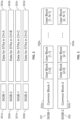
- FIG. 2 provides an example block diagram illustrating an example MU frame at 80MHz, according to some embodiments described herein.
- the MU frame may include a high efficiency (HE) preamble portion containing an HE signal field A (SIGA) and an HE signal field B (HE-SIGB).
- HE high efficiency
- SIGA HE signal field A
- HE-SIGB HE signal field B
- the SIGB is used to signal the resource unit (RU) signaling and physical layer (PHY) configuration for each station.
- RU resource unit
- PHY physical layer
- two SIGBs can be constructed and each carries different scheduling information.
- the two SIGBs e.g., SIGB-1 and SIGB-2, can each be transmitted at a frequency of over 20MHz, and may be duplicated over other channels at 20MHz. As shown in FIG.
- the field SIGB-1 201a can include scheduling information for data for stations on channel A (203a), and another field SIGB-2 202a can include scheduling information for data for stations on channel B (203b).
- the fields SIGB-1 and SIGB-2 can be duplicated (201b and 202b) for scheduling information for data for stations on additional channels, such as channels C and D (203c-d), respectively.
- FIG. 3 provides an example block diagram illustrating exemplary data information carried by two SIGB fields, according to some embodiments described herein.
- Each SIGB 301 or 302 may include a not-fully-duplicated common block 303a or 303b, respectively, e.g., the common block 303a or 303b may each carry RU signaling (resource allocation) information for the channels that the respective SIGB covers.
- common block 303a may carry RU signaling information for channel A (e.g., if there are two client stations on channel A, each may be allocated to 10MHz), and common block 303b may carry RU signaling information for channel B (e.g., if there are two client stations on channel B, one may be allocated 5MHz and the other may be allocated 15MHz, etc.).
- the user blocks 305a and 305b may carry PHY configuration information for each scheduled station that chooses the respective SIGB to carry its information.
- a scheduling mechanism that adopts the two SIGBs needs to provide a SIGB and station mapping scheme that identifies whose information is to be carried in which SIGB.
- FIG. 4 provides an example block diagram illustrating an exemplary SIGB and station mapping scheme for a bandwidth of 40MHz, according to some embodiments described herein.
- the fields SIGB-1 401 and SIGB-2 402 may each cover a 20MHz channel, e.g., SIGB-1 401 carries scheduling information relating to transmitting data 403 for stations on channel A, and SIGB-2 402 carries information relating to transmitting data 404 for stations on channel B.
- Each SIGB 401 or 402 contains a common block 405 including resource allocation information for the respective channel the SIGB is transmitted on, e.g., SIGB-1 401 includes a common block storing information for channel A, and SIGB-2 402 includes a common block storing information for channel B.
- Each common block 405 is followed by the associated user blocks 407 that include user data transmitted to/from the multiple stations on the respective channel.
- FIG. 5 provides an example block diagram illustrating an exemplary SIGB and station mapping scheme for data transmission at a bandwidth greater than 40MHz, according to some embodiments described herein.
- each SIGB may cover a set of channels.
- each SIGB 501 or 502 contains a common block 503 or 504 including RU signaling information for a set of a few channels, and the STAs scheduled on the respective set of channels may have their user blocks 505 or 506 also in the respective SIGB.
- a single SIGB may cover different channels, and thus cross-channel scheduling is realized via the data structure shown in FIG. 5 .
- the channel-to-SIGB mapping is flexible, e.g., the SIGB-1 501 or SIGB-2 502 can be mapped to different channels.
- the numbers of channels covered by each SIGB 501 or 502 may not be necessarily the same, e.g., SIGB-1 501 may cover two channels, and SIGB-2 502 may cover four channels.
- the channel-SIGB mapping information may be signaled in the SIGA field.
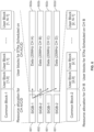
- FIG. 6 provides an example block diagram illustrating an exemplary SIGB and station mapping scheme for data transmission at 80MHz, according to some embodiments described herein.
- the grouping of ⁇ A, C, D ⁇ and ⁇ B ⁇ can have a balanced payload for each SIGB.
- SIGB-1 601 While on PHY the data for channel D 602d is transmitted following a SIGB-2 601 (as SIGB-1 and SIGB-2 fields are transmitted or received alternatively in a sequence), resource allocation information for channel D is carried by SIGB-1 601, and thus the scheduling is cross-channel.
- FIG. 7 provides a logic flow diagram illustrating aspects of cross-channel scheduling mapping and signaling, according to a claimed embodiment.
- the AP e.g., 110 in FIG. 1
- retrieves channel information and user/client information such as the available bandwidth for data transmission (e.g., 20MHz, 40MHz, 80MHz, or more, etc.), the number of available channels (e.g., two 20MHz channels, four 20MHz channels, etc.), the number of clients/stations for data transmission with the AP, client-channel mapping information, and/or the like.
- the AP determines , e.g., via the host processor 105 in FIG. 1 , whether the payload for each SIGB is balanced. For example, if each channel A, B, C and D has two client/stations transmitting thereon, the data load for SIGB-1 and SIGB-2 may be similar, and thus the channel-SIGB mapping is considered balanced. In a different example, if channel A has five clients/stations, but each of the channels B, C and D has only one client/station, the SIGB that carries information for the channel set ⁇ A,C ⁇ may have an unbalanced higher data load compared to the other SIGB that carries information for the channel set ⁇ B,D ⁇ . Rebalancing of the channel-SIGB mapping is performed.
- the AP When the channel-SIGB mapping is balanced at 703, the AP maintains the current channel-SIGB (e.g., the default setting) mapping for data transmission at 705. Otherwise, the AP may re-map the channels to SIGB. For example, for a bandwidth of 80MHz, the number of channels in each channel set covered by each SIGB can be ⁇ 2, 2 ⁇ , ⁇ 1, 3 ⁇ , ⁇ 3, 1 ⁇ .
- one channel may be moved from one SIGB to another SIGB, e.g., the channel sets can be moved from ⁇ A, C ⁇ , ⁇ B, D ⁇ to ⁇ A ⁇ , ⁇ B, C, D ⁇ .
- the updated channel-SIGB mapping information is configured in the SIGA bits, at 706.
- any "1” in the bitmap indicates the corresponding channel to be mapped to another SIGB.
- "10” represents that a first channel from the set is to be moved to the other set
- "01" represents that a second channel from the set is to be moved to the other set.
- a bitmap "00" means that the rebalance is off.
- the order of bits can be arbitrary as long as it is pre-defined.
- the 3 bits of "011" in SIGA may indicate that the second bit "1" represents a move from SIGB-2 to SIGB-1; the first bit "0” represents the first channel of the channel set to be moved from; and the third bit "1" represents that the cross-channel-scheduling is on.
- "011” means channel C is moved from set 2 to set 1 for cross-channel scheduling.
- the order of bits can be arbitrary as long as it is pre-defined.
- the number of channels in channel set 1 and set 2 covered by each SIGB, respectively can be ⁇ 4, 4 ⁇ , ⁇ 3, 5 ⁇ , ⁇ 5, 3 ⁇ , ⁇ 2, 6 ⁇ , ⁇ 6, 2 ⁇ , ⁇ 1, 7 ⁇ , ⁇ 7, 1 ⁇ .
- the numbers of channels in each channel set may change from the default ⁇ 4, 4 ⁇ to ⁇ 4, 4 ⁇ , ⁇ 3, 5 ⁇ or ⁇ 5, 3 ⁇ .
- a codebook or table can be used to list the channel mapping.
- an additional rebalancing method can be incorporated. For example, options with more than one channel to be moved can be added at 704. Or, options with channel swapping can be added.
- the codebook/table can be constructed as shown in Table 1: Table 1.
- Table 1 Example Channel-SIGB Mapping Table for 80MHz, 2 Bits B0B1 CH-to-SIGB Map 00 AC/BD 01 AD/BC 10 AC D /B 11 A/BD C
- "10" and "11” shows the scenarios when only one channel is moved from one SIGB to the other SIGB from "00" (the underlined channel is the channel that has been moved from another SIGB).
- the codebook/table can be constructed as shown in Table 2: Table 2.
- Table 2 Example Channel-SIGB Mapping Table for 80MHz, 3 Bits B0 ⁇ B2 CH-to-SIGB Map 000 AC/BD 001 AB/CD 010 AD/BC 011 ABC/D 100 ACD/B 101 A/BCD 110 rsvd 111 rsvd
- all options of channel sets for 80MHz can be included.
- the codebook/table can be constructed as shown in Table 3: Table 3.
- the underlined channels in Table 4 are the channels that have been moved from another SIGB.
- the channel-SIGB mapping can be designed such that SIGB can cover all the channels.
- the signaling in SIGA can include a bitmap of N bits, where N denotes the number of channels (e.g., four for 80MHz, and eight for 160MHz).
- a "1" in the bitmap in the corresponding channel belongs to one SIGB (e.g., "1" can be designated to denote SIGB-1, and "0" can be designated to denote SIGB-2; or vice versa), and the "0" indicates the corresponding channel belongs to the other SIGB.
- a four-bit string XXXX can be used in the bitmap, e.g., "0101" represents that channels A and C are carried by SIGB-2 and B and D are carried by SIGB-1; and "0001" represents channel A, B, C are carried by SIGB-2, and channel D is carried by SIGB-1, and/or the like.
- a channel identification subfield can be added in each SIGB's common block (e.g., common blocks 303a or 303b in FIG. 3 ).
- the channels in one SIGB can be assigned successively from a predefined order. For example, if three channels are covered by SIGB-1, then they are channels A-C from the four channels of 80MHz. Or the channels can be alternatively assigned to each SIGB.
- SIGB-1 the rest of the unassigned channels go to the unfilled SIGB. For example, if three channels are covered by SIGB-1, then channels A, C and E are covered by SIGB-1, and channels B, D, F, G and H go to SIGB-2.
- the AP transmits data to the multiple stations on the respective channel based on the SIGA and SIGB information.
- the channel condition or client condition changes e.g., available bandwidth changes or more clients are added for transmission
- the AP starts at 701 for possible rebalancing of channel-SIGB mapping again.
- Suitable computer program code residing on a computer-readable medium may be provided for performing one or more functions in relation to performing the processes as described herein.
- the term "computer-readable medium” as used herein refers to any non-transitory or transitory medium that provides or participates in providing instructions to a processor of the computing device (e.g., the BLE device 106a-b, the receiving server 105, or any other processor of a device described herein) for execution.
- a medium may take many forms, including but not limited to non-volatile media and volatile media.
- Nonvolatile media include, for example, optical, magnetic, or opto-magnetic disks, or integrated circuit memory, such as flash memory.
- Volatile media include dynamic random access memory (DRAM), which typically constitutes the main memory.
- Computer-readable media include, for example, a floppy disk, a flexible disk, hard disk, magnetic tape, any other magnetic medium, a CD-ROM, DVD, any other optical medium, punch cards, paper tape, any other physical medium with patterns of holes, a RAM, a PROM, an EPROM or EEPROM (electronically erasable programmable read-only memory), a FLASH-EEPROM, any other memory chip or cartridge, or any other non-transitory medium from which a computer can read.
- a floppy disk a flexible disk, hard disk, magnetic tape, any other magnetic medium, a CD-ROM, DVD, any other optical medium, punch cards, paper tape, any other physical medium with patterns of holes, a RAM, a PROM, an EPROM or EEPROM (electronically erasable programmable read-only memory), a FLASH-EEPROM, any other memory chip or cartridge, or any other non-transitory medium from which a computer can read.
Landscapes
- Engineering & Computer Science (AREA)
- Signal Processing (AREA)
- Computer Networks & Wireless Communication (AREA)
- Mobile Radio Communication Systems (AREA)
Claims (12)
- Verfahren zur kanalübergreifenden Ablaufplanung einer hocheffizienten HE-Mehrbenutzer-MU-Rahmenübertragung, wobei das Verfahren umfasst:Erhalten (701) von Kanalinformationen und Client-Stationsinformationen für die Datenübertragung;Konfigurieren (702) eines MU-Rahmens, der ein Datenfeld eines ersten Typs und zwei Datenfelder eines zweiten Typs enthält, um Planungsinformationen zu tragen, die sich darauf beziehen, welcher Kanal von einem oder mehreren Kanälen für die MU-Rahmenübertragung zu verwenden ist, wobei ein erstes Datenfeld der zwei Datenfelder des zweiten Typs einen ersten Satz von Kanälen von dem einen oder den mehreren Kanälen abdeckt, und ein zweites Datenfeld der zwei Datenfelder des zweiten Typs einen zweiten Satz von Kanälen von dem einen oder den mehreren Kanälen abdeckt;Bestimmen (703), dass eine aktuelle Planungseinstellung der zwei Datenfelder des zweiten Typs zu unausgeglichener Nutzlast zwischen dem einen oder den mehreren Kanälen führt;Anpassen (704) der beiden Datenfelder des zweiten Typs durch Neuzuordnung von Kanälen von dem ersten Datenfeld zu dem zweiten Datenfeld für eine ausgeglichene Kanalzuordnung;Einstellen (706) des Datenfeldes des ersten Typs, um die ausgeglichene Kanalabbildung widerzuspiegeln, indem eine Vielzahl von Bits in dem Datenfeld des ersten Typs bezeichnet wird, um ein sich änderndes Muster von der aktuellen Planungseinstellung darzustellen; undÜbertragen (707) von Daten über den einen oder die mehreren Kanäle, basierend auf dem angepassten Datenfeld des ersten Typs und den angepassten zwei Datenfeldern des zweiten Typs.
- Verfahren nach Anspruch 1, wobei jedes der beiden Datenfelder des zweiten Typs Ressourcenzuweisungsinformationen enthält, die sich auf eine oder mehrere Client-Stationen (120a, 120b, 120c) auf einem Kanal beziehen, den das jeweilige Datenfeld des zweiten Typs abdeckt.
- Verfahren nach einem der Ansprüche 1 oder 2, wobei das Datenfeld des ersten Typs Zuordnungsinformationen zwischen den beiden Datenfeldern des zweiten Typs und dem einen oder den mehreren Kanälen enthält.
- Verfahren nach Anspruch 1, wobei das Anpassen (704) der beiden Datenfelder des zweiten Typs für eine ausgeglichene Kanalabbildung Folgendes umfasst:
Vertauschen eines ersten Kanals aus dem ersten Satz mit einem zweiten Kanal aus dem zweiten Satz. - Verfahren nach einem der Ansprüche 1 bis 4,
wobei die Vielzahl von Bits eine Kanal-Bitmap enthält; oder wobei das Verfahren ferner umfasst:
Abrufen einer zuvor gespeicherten Datentabelle, die die Vielzahl von Bits auf Kanalabbildungsmuster abbildet. - Verfahren nach einem der Ansprüche 1 bis 5, wobei die übertragenen Daten einen neuen MU-Rahmen enthalten, der das angepasste Datenfeld des ersten Typs und die angepassten zwei Datenfelder des zweiten Typs enthält, und
wobei der neue MU-Rahmen an einem Empfänger decodiert wird, damit der Empfänger Kanalabbildungsinformationen und Ressourcenzuordnungsinformationen aus dem angepassten Datenfeld des ersten Typs und den angepassten zwei Datenfeldern des zweiten Typs erhält. - System zur kanalübergreifenden Ablaufplanung einer hocheffizienten HE-Mehrbenutzer-MU-Rahmenübertragung, wobei das System Folgendes umfasst
eine Verarbeitungsschaltung (105, 125), die konfiguriert ist, zum:Erhalten (701) von Kanalinformationen und Client-Stationsinformationen für die Datenübertragung,Konfigurieren (702) eines MU-Rahmens, der ein Datenfeld eines ersten Typs und zwei Datenfelder eines zweiten Typs enthält, um Planungsinformationen zu tragen, die sich darauf beziehen, welcher Kanal von einem oder mehreren Kanälen für die MU-Rahmenübertragung verwendet werden soll, wobei ein erstes Datenfeld der zwei Datenfelder des zweiten Typs einen ersten Satz von Kanälen von dem einen oder den mehreren Kanälen abdeckt, und ein zweites Datenfeld der zwei Datenfelder des zweiten Typs einen zweiten Satz von Kanälen von dem einen oder den mehreren Kanälen abdeckt,Bestimmen (703), dass eine aktuelle Planungseinstellung der zwei Datenfelder des zweiten Typs zu einer unausgewogenen Nutzlast zwischen dem einen oder den mehreren Kanälen führt, Anpassen (704) der beiden Datenfelder des zweiten Typs durch Neuzuordnung von Kanälen von dem ersten Datenfeld zu dem zweiten Datenfeld für eine ausgeglichene Kanalzuordnung, undAnpassen (706) des Datenfeldes des ersten Typs, um die ausgeglichene Kanalabbildung widerzuspiegeln, indem eine Mehrzahl von Bits in dem Datenfeld des ersten Typs bezeichnet wird, um ein sich änderndes Muster von der aktuellen Planungseinstellung darzustellen; undeine Netzwerkschnittstelle (107), die so konfiguriert ist, dass sie über den einen oder die mehreren Kanäle Daten basierend auf dem angepassten Datenfeld des ersten Typs und den angepassten zwei Datenfeldern des zweiten Typs überträgt (707). - System nach Anspruch 7,
wobei jedes der beiden Datenfelder des zweiten Typs Ressourcenzuordnungsinformationen enthält, die sich auf eine oder mehrere Client-Stationen (120a, 120b, 120c) auf einem Kanal beziehen, den das jeweilige Datenfeld des zweiten Typs abdeckt. - System nach Anspruch 7 oder 8, wobei das Datenfeld des ersten Typs Zuordnungsinformationen zwischen den beiden Datenfeldern des zweiten Typs und dem einen oder den mehreren Kanälen enthält.
- System nach Anspruch 7, wobei der Prozessor ferner konfiguriert ist, um:
Vertauschen eines ersten Kanals aus dem ersten Satz mit einem zweiten Kanal aus dem zweiten Satz. - System nach Anspruch 7, wobei die Vielzahl von Bits eine Kanal-Bitmap enthält; oder wobei der Prozessor weiterhin konfiguriert ist, um:
eine zuvor gespeicherte Datentabelle abzurufen, die die Vielzahl von Bits auf Kanalabbildungsmuster abbildet. - System nach einem der Ansprüche 7 bis 11, wobei die übertragenen Daten einen neuen MU-Rahmen enthalten, der das angepasste Datenfeld des ersten Typs und die angepassten zwei Datenfelder des zweiten Typs enthält, und
wobei der neue MU-Rahmen an einem Empfänger decodiert wird, damit der Empfänger Kanalabbildungsinformationen und Ressourcenzuordnungsinformationen aus dem angepassten Datenfeld des ersten Typs und den angepassten zwei Datenfeldern des zweiten Typs erhält.
Applications Claiming Priority (4)
| Application Number | Priority Date | Filing Date | Title |
|---|---|---|---|
| US201562216547P | 2015-09-10 | 2015-09-10 | |
| US201562233823P | 2015-09-28 | 2015-09-28 | |
| US201562246319P | 2015-10-26 | 2015-10-26 | |
| PCT/US2016/051333 WO2017044956A1 (en) | 2015-09-10 | 2016-09-12 | Systems and methods for cross-channel scheduling of high efficiency (he) multi-user (mu) frame transmission |
Publications (2)
| Publication Number | Publication Date |
|---|---|
| EP3348104A1 EP3348104A1 (de) | 2018-07-18 |
| EP3348104B1 true EP3348104B1 (de) | 2024-10-30 |
Family
ID=58237394
Family Applications (1)
| Application Number | Title | Priority Date | Filing Date |
|---|---|---|---|
| EP16770616.7A Active EP3348104B1 (de) | 2015-09-10 | 2016-09-12 | Systeme und verfahren zur kanalübergreifenden planung von rahmenübertragung mit hoher effizienz (hr) und mehreren benutzern (mu) |
Country Status (4)
| Country | Link |
|---|---|
| US (2) | US10164745B2 (de) |
| EP (1) | EP3348104B1 (de) |
| CN (2) | CN114501652A (de) |
| WO (1) | WO2017044956A1 (de) |
Families Citing this family (3)
| Publication number | Priority date | Publication date | Assignee | Title |
|---|---|---|---|---|
| US10063666B2 (en) | 2016-06-14 | 2018-08-28 | Futurewei Technologies, Inc. | Modular telecommunication edge cloud system |
| FR3075549B1 (fr) | 2017-12-19 | 2019-12-27 | Sagemcom Broadband Sas | Procede de transmission de trame par un point d'acces d'un reseau local sans-fil |
| CN111970761B (zh) * | 2019-05-20 | 2025-05-13 | 华为技术有限公司 | 资源分配的指示方法及装置 |
Family Cites Families (8)
| Publication number | Priority date | Publication date | Assignee | Title |
|---|---|---|---|---|
| RU2490829C2 (ru) * | 2008-02-04 | 2013-08-20 | Нокиа Сименс Нетуоркс Ой | Отображение циклического сдвига на индекс канала для назначения ресурсов ack/nack |
| US9089002B2 (en) * | 2010-05-16 | 2015-07-21 | Qualcomm Incorporated | Efficient group ID management for wireless local area networks (WLANs) |
| BR112014019295A8 (pt) * | 2012-02-05 | 2017-07-11 | Lg Electronics Inc | Processo e aparelho para acesso a canal por meio de quadro de pacotes de dados nulos em sistema lan sem fio |
| US9699779B2 (en) * | 2012-08-23 | 2017-07-04 | Interdigital Patent Holdings, Inc. | Physical layer operation for multi-layer operation in a wireless system |
| US10439773B2 (en) * | 2013-04-15 | 2019-10-08 | Qualcomm Incorporated | Systems and methods for backwards-compatible preamble formats for multiple access wireless communication |
| US9729285B2 (en) * | 2013-06-13 | 2017-08-08 | Avago Technologies General Ip (Singapore) Pte. Ltd | Flexible OFDMA packet structure for wireless communications |
| US20150163028A1 (en) * | 2013-12-10 | 2015-06-11 | Qualcomm Incorporated | Methods and apparatus for wireless communication utilizing efficient signal field design in high efficiency wireless packets |
| EP3139532B1 (de) * | 2015-09-07 | 2018-12-12 | MediaTek Inc. | Formate und zuordnung des gemeinsamen feldes von he-sig-b |
-
2016
- 2016-09-12 EP EP16770616.7A patent/EP3348104B1/de active Active
- 2016-09-12 US US15/262,905 patent/US10164745B2/en active Active
- 2016-09-12 WO PCT/US2016/051333 patent/WO2017044956A1/en not_active Ceased
- 2016-09-12 CN CN202210117625.0A patent/CN114501652A/zh active Pending
- 2016-09-12 CN CN201680052577.4A patent/CN108029114B/zh active Active
-
2018
- 2018-12-19 US US16/226,177 patent/US11005617B2/en active Active
Also Published As
| Publication number | Publication date |
|---|---|
| EP3348104A1 (de) | 2018-07-18 |
| CN108029114A (zh) | 2018-05-11 |
| US20190273589A1 (en) | 2019-09-05 |
| CN114501652A (zh) | 2022-05-13 |
| US20170078059A1 (en) | 2017-03-16 |
| WO2017044956A1 (en) | 2017-03-16 |
| US10164745B2 (en) | 2018-12-25 |
| CN108029114B (zh) | 2022-02-18 |
| US11005617B2 (en) | 2021-05-11 |
Similar Documents
| Publication | Publication Date | Title |
|---|---|---|
| JP7059393B2 (ja) | ダウンリンク制御情報伝送方法 | |
| JP5967218B2 (ja) | 下り制御チャネルのサーチ空間のマッピング方法及び装置 | |
| US10959243B2 (en) | Systems and methods for providing resource signaling within a wireless local area network (WLAN) | |
| KR102164280B1 (ko) | Wlan 시스템 자원 지시 방법 및 장치 | |
| US9426793B2 (en) | Apparatus and method for allocating resource using codebook based on resource size and burst size in broadband wireless communication system | |
| CN105846976A (zh) | 无线通信系统中的多用户多输入多输出传输方法和基站 | |
| CN116390250A (zh) | 一种ppdu的传输方法及相关装置 | |
| US11005617B2 (en) | Systems and methods for cross-channel scheduling of high efficiency (HE) multi-user (MU) frame transmission | |
| KR20110124160A (ko) | 복수의 세그먼트 주파수 대역을 이용하는 무선 통신 시스템에서 다중 사용자에게 프레임을 전송하는 방법 및 이의 수신 방법 | |
| US9743393B2 (en) | Dynamic patterned resource allocation in a wireless network | |
| CN110838906B (zh) | Wlan ofdma中的控制信道 | |
| EP4195572B1 (de) | Ressourcenpoolverarbeitungsverfahren, vorrichtung und speichermedium | |
| CN103634802A (zh) | 一种用于分配频率资源的方法和设备 | |
| CN105119851B (zh) | 无线局域网通信方法和设备 | |
| AU2020234382B2 (en) | Communications in spatial streams | |
| CN112399575B (zh) | 通信方法及装置 | |
| JP6401062B2 (ja) | 無線通信装置、無線通信方法およびプログラム |
Legal Events
| Date | Code | Title | Description |
|---|---|---|---|
| STAA | Information on the status of an ep patent application or granted ep patent |
Free format text: STATUS: THE INTERNATIONAL PUBLICATION HAS BEEN MADE |
|
| PUAI | Public reference made under article 153(3) epc to a published international application that has entered the european phase |
Free format text: ORIGINAL CODE: 0009012 |
|
| STAA | Information on the status of an ep patent application or granted ep patent |
Free format text: STATUS: REQUEST FOR EXAMINATION WAS MADE |
|
| 17P | Request for examination filed |
Effective date: 20180227 |
|
| AK | Designated contracting states |
Kind code of ref document: A1 Designated state(s): AL AT BE BG CH CY CZ DE DK EE ES FI FR GB GR HR HU IE IS IT LI LT LU LV MC MK MT NL NO PL PT RO RS SE SI SK SM TR |
|
| AX | Request for extension of the european patent |
Extension state: BA ME |
|
| DAV | Request for validation of the european patent (deleted) | ||
| DAX | Request for extension of the european patent (deleted) | ||
| STAA | Information on the status of an ep patent application or granted ep patent |
Free format text: STATUS: EXAMINATION IS IN PROGRESS |
|
| 17Q | First examination report despatched |
Effective date: 20190412 |
|
| RAP1 | Party data changed (applicant data changed or rights of an application transferred) |
Owner name: MARVELL ASIA PTE, LTD. |
|
| P01 | Opt-out of the competence of the unified patent court (upc) registered |
Effective date: 20230509 |
|
| GRAP | Despatch of communication of intention to grant a patent |
Free format text: ORIGINAL CODE: EPIDOSNIGR1 |
|
| STAA | Information on the status of an ep patent application or granted ep patent |
Free format text: STATUS: GRANT OF PATENT IS INTENDED |
|
| INTG | Intention to grant announced |
Effective date: 20240604 |
|
| GRAS | Grant fee paid |
Free format text: ORIGINAL CODE: EPIDOSNIGR3 |
|
| GRAA | (expected) grant |
Free format text: ORIGINAL CODE: 0009210 |
|
| STAA | Information on the status of an ep patent application or granted ep patent |
Free format text: STATUS: THE PATENT HAS BEEN GRANTED |
|
| AK | Designated contracting states |
Kind code of ref document: B1 Designated state(s): AL AT BE BG CH CY CZ DE DK EE ES FI FR GB GR HR HU IE IS IT LI LT LU LV MC MK MT NL NO PL PT RO RS SE SI SK SM TR |
|
| REG | Reference to a national code |
Ref country code: GB Ref legal event code: FG4D |
|
| REG | Reference to a national code |
Ref country code: CH Ref legal event code: EP |
|
| REG | Reference to a national code |
Ref country code: IE Ref legal event code: FG4D |
|
| REG | Reference to a national code |
Ref country code: DE Ref legal event code: R096 Ref document number: 602016090042 Country of ref document: DE |
|
| REG | Reference to a national code |
Ref country code: LT Ref legal event code: MG9D |
|
| REG | Reference to a national code |
Ref country code: NL Ref legal event code: MP Effective date: 20241030 |
|
| PG25 | Lapsed in a contracting state [announced via postgrant information from national office to epo] |
Ref country code: IS Free format text: LAPSE BECAUSE OF FAILURE TO SUBMIT A TRANSLATION OF THE DESCRIPTION OR TO PAY THE FEE WITHIN THE PRESCRIBED TIME-LIMIT Effective date: 20250228 Ref country code: PT Free format text: LAPSE BECAUSE OF FAILURE TO SUBMIT A TRANSLATION OF THE DESCRIPTION OR TO PAY THE FEE WITHIN THE PRESCRIBED TIME-LIMIT Effective date: 20250228 Ref country code: HR Free format text: LAPSE BECAUSE OF FAILURE TO SUBMIT A TRANSLATION OF THE DESCRIPTION OR TO PAY THE FEE WITHIN THE PRESCRIBED TIME-LIMIT Effective date: 20241030 |
|
| PG25 | Lapsed in a contracting state [announced via postgrant information from national office to epo] |
Ref country code: FI Free format text: LAPSE BECAUSE OF FAILURE TO SUBMIT A TRANSLATION OF THE DESCRIPTION OR TO PAY THE FEE WITHIN THE PRESCRIBED TIME-LIMIT Effective date: 20241030 Ref country code: NL Free format text: LAPSE BECAUSE OF FAILURE TO SUBMIT A TRANSLATION OF THE DESCRIPTION OR TO PAY THE FEE WITHIN THE PRESCRIBED TIME-LIMIT Effective date: 20241030 |
|
| REG | Reference to a national code |
Ref country code: AT Ref legal event code: MK05 Ref document number: 1738176 Country of ref document: AT Kind code of ref document: T Effective date: 20241030 |
|
| PG25 | Lapsed in a contracting state [announced via postgrant information from national office to epo] |
Ref country code: BG Free format text: LAPSE BECAUSE OF FAILURE TO SUBMIT A TRANSLATION OF THE DESCRIPTION OR TO PAY THE FEE WITHIN THE PRESCRIBED TIME-LIMIT Effective date: 20241030 |
|
| PG25 | Lapsed in a contracting state [announced via postgrant information from national office to epo] |
Ref country code: ES Free format text: LAPSE BECAUSE OF FAILURE TO SUBMIT A TRANSLATION OF THE DESCRIPTION OR TO PAY THE FEE WITHIN THE PRESCRIBED TIME-LIMIT Effective date: 20241030 |
|
| PG25 | Lapsed in a contracting state [announced via postgrant information from national office to epo] |
Ref country code: NO Free format text: LAPSE BECAUSE OF FAILURE TO SUBMIT A TRANSLATION OF THE DESCRIPTION OR TO PAY THE FEE WITHIN THE PRESCRIBED TIME-LIMIT Effective date: 20250130 |
|
| PG25 | Lapsed in a contracting state [announced via postgrant information from national office to epo] |
Ref country code: GR Free format text: LAPSE BECAUSE OF FAILURE TO SUBMIT A TRANSLATION OF THE DESCRIPTION OR TO PAY THE FEE WITHIN THE PRESCRIBED TIME-LIMIT Effective date: 20250131 Ref country code: AT Free format text: LAPSE BECAUSE OF FAILURE TO SUBMIT A TRANSLATION OF THE DESCRIPTION OR TO PAY THE FEE WITHIN THE PRESCRIBED TIME-LIMIT Effective date: 20241030 Ref country code: LV Free format text: LAPSE BECAUSE OF FAILURE TO SUBMIT A TRANSLATION OF THE DESCRIPTION OR TO PAY THE FEE WITHIN THE PRESCRIBED TIME-LIMIT Effective date: 20241030 |
|
| PG25 | Lapsed in a contracting state [announced via postgrant information from national office to epo] |
Ref country code: PL Free format text: LAPSE BECAUSE OF FAILURE TO SUBMIT A TRANSLATION OF THE DESCRIPTION OR TO PAY THE FEE WITHIN THE PRESCRIBED TIME-LIMIT Effective date: 20241030 |
|
| PG25 | Lapsed in a contracting state [announced via postgrant information from national office to epo] |
Ref country code: RS Free format text: LAPSE BECAUSE OF FAILURE TO SUBMIT A TRANSLATION OF THE DESCRIPTION OR TO PAY THE FEE WITHIN THE PRESCRIBED TIME-LIMIT Effective date: 20250130 |
|
| PG25 | Lapsed in a contracting state [announced via postgrant information from national office to epo] |
Ref country code: SM Free format text: LAPSE BECAUSE OF FAILURE TO SUBMIT A TRANSLATION OF THE DESCRIPTION OR TO PAY THE FEE WITHIN THE PRESCRIBED TIME-LIMIT Effective date: 20241030 |
|
| PG25 | Lapsed in a contracting state [announced via postgrant information from national office to epo] |
Ref country code: DK Free format text: LAPSE BECAUSE OF FAILURE TO SUBMIT A TRANSLATION OF THE DESCRIPTION OR TO PAY THE FEE WITHIN THE PRESCRIBED TIME-LIMIT Effective date: 20241030 |
|
| PG25 | Lapsed in a contracting state [announced via postgrant information from national office to epo] |
Ref country code: EE Free format text: LAPSE BECAUSE OF FAILURE TO SUBMIT A TRANSLATION OF THE DESCRIPTION OR TO PAY THE FEE WITHIN THE PRESCRIBED TIME-LIMIT Effective date: 20241030 |
|
| PG25 | Lapsed in a contracting state [announced via postgrant information from national office to epo] |
Ref country code: RO Free format text: LAPSE BECAUSE OF FAILURE TO SUBMIT A TRANSLATION OF THE DESCRIPTION OR TO PAY THE FEE WITHIN THE PRESCRIBED TIME-LIMIT Effective date: 20241030 |
|
| PG25 | Lapsed in a contracting state [announced via postgrant information from national office to epo] |
Ref country code: SK Free format text: LAPSE BECAUSE OF FAILURE TO SUBMIT A TRANSLATION OF THE DESCRIPTION OR TO PAY THE FEE WITHIN THE PRESCRIBED TIME-LIMIT Effective date: 20241030 |
|
| PG25 | Lapsed in a contracting state [announced via postgrant information from national office to epo] |
Ref country code: CZ Free format text: LAPSE BECAUSE OF FAILURE TO SUBMIT A TRANSLATION OF THE DESCRIPTION OR TO PAY THE FEE WITHIN THE PRESCRIBED TIME-LIMIT Effective date: 20241030 |
|
| PG25 | Lapsed in a contracting state [announced via postgrant information from national office to epo] |
Ref country code: IT Free format text: LAPSE BECAUSE OF FAILURE TO SUBMIT A TRANSLATION OF THE DESCRIPTION OR TO PAY THE FEE WITHIN THE PRESCRIBED TIME-LIMIT Effective date: 20241030 |
|
| REG | Reference to a national code |
Ref country code: DE Ref legal event code: R097 Ref document number: 602016090042 Country of ref document: DE |
|
| PLBE | No opposition filed within time limit |
Free format text: ORIGINAL CODE: 0009261 |
|
| STAA | Information on the status of an ep patent application or granted ep patent |
Free format text: STATUS: NO OPPOSITION FILED WITHIN TIME LIMIT |
|
| PG25 | Lapsed in a contracting state [announced via postgrant information from national office to epo] |
Ref country code: SE Free format text: LAPSE BECAUSE OF FAILURE TO SUBMIT A TRANSLATION OF THE DESCRIPTION OR TO PAY THE FEE WITHIN THE PRESCRIBED TIME-LIMIT Effective date: 20241030 |
|
| 26N | No opposition filed |
Effective date: 20250731 |
|
| PGFP | Annual fee paid to national office [announced via postgrant information from national office to epo] |
Ref country code: DE Payment date: 20250926 Year of fee payment: 10 |
|
| PGFP | Annual fee paid to national office [announced via postgrant information from national office to epo] |
Ref country code: GB Payment date: 20250923 Year of fee payment: 10 |
|
| PGFP | Annual fee paid to national office [announced via postgrant information from national office to epo] |
Ref country code: FR Payment date: 20250925 Year of fee payment: 10 |
|
| REG | Reference to a national code |
Ref country code: CH Ref legal event code: H13 Free format text: ST27 STATUS EVENT CODE: U-0-0-H10-H13 (AS PROVIDED BY THE NATIONAL OFFICE) Effective date: 20260504 |
|
| PG25 | Lapsed in a contracting state [announced via postgrant information from national office to epo] |
Ref country code: LU Free format text: LAPSE BECAUSE OF NON-PAYMENT OF DUE FEES Effective date: 20250912 |
|
| REG | Reference to a national code |
Ref country code: BE Ref legal event code: MM Effective date: 20250930 |
|
| PG25 | Lapsed in a contracting state [announced via postgrant information from national office to epo] |
Ref country code: LT Free format text: LAPSE BECAUSE OF FAILURE TO SUBMIT A TRANSLATION OF THE DESCRIPTION OR TO PAY THE FEE WITHIN THE PRESCRIBED TIME-LIMIT Effective date: 20241030 |
|
| PG25 | Lapsed in a contracting state [announced via postgrant information from national office to epo] |
Ref country code: MC Free format text: LAPSE BECAUSE OF FAILURE TO SUBMIT A TRANSLATION OF THE DESCRIPTION OR TO PAY THE FEE WITHIN THE PRESCRIBED TIME-LIMIT Effective date: 20241030 |
|
| PG25 | Lapsed in a contracting state [announced via postgrant information from national office to epo] |
Ref country code: IE Free format text: LAPSE BECAUSE OF NON-PAYMENT OF DUE FEES Effective date: 20250912 Ref country code: BE Free format text: LAPSE BECAUSE OF NON-PAYMENT OF DUE FEES Effective date: 20250930 Ref country code: CH Free format text: LAPSE BECAUSE OF NON-PAYMENT OF DUE FEES Effective date: 20250930 |