EP3348127A1 - Bodenbearbeitungsvorrichtung einer ackerbaumaschine - Google Patents
Bodenbearbeitungsvorrichtung einer ackerbaumaschine Download PDFInfo
- Publication number
- EP3348127A1 EP3348127A1 EP16844019.6A EP16844019A EP3348127A1 EP 3348127 A1 EP3348127 A1 EP 3348127A1 EP 16844019 A EP16844019 A EP 16844019A EP 3348127 A1 EP3348127 A1 EP 3348127A1
- Authority
- EP
- European Patent Office
- Prior art keywords
- tilling
- support member
- claws
- row
- tilling claws
- Prior art date
- Legal status (The legal status is an assumption and is not a legal conclusion. Google has not performed a legal analysis and makes no representation as to the accuracy of the status listed.)
- Withdrawn
Links
Images





Classifications
-
- A—HUMAN NECESSITIES
- A01—AGRICULTURE; FORESTRY; ANIMAL HUSBANDRY; HUNTING; TRAPPING; FISHING
- A01B—SOIL WORKING IN AGRICULTURE OR FORESTRY; PARTS, DETAILS, OR ACCESSORIES OF AGRICULTURAL MACHINES OR IMPLEMENTS, IN GENERAL
- A01B33/00—Tilling implements with rotary driven tools, e.g. in combination with fertiliser distributors or seeders, with grubbing chains, with sloping axles, with driven discs
- A01B33/08—Tools; Details, e.g. adaptations of transmissions or gearings
- A01B33/10—Structural or functional features of the tools ; Theoretical aspects of the cutting action
- A01B33/103—Structural or functional features of the tools ; Theoretical aspects of the cutting action the rotating shaft being oriented horizontally
-
- A—HUMAN NECESSITIES
- A01—AGRICULTURE; FORESTRY; ANIMAL HUSBANDRY; HUNTING; TRAPPING; FISHING
- A01B—SOIL WORKING IN AGRICULTURE OR FORESTRY; PARTS, DETAILS, OR ACCESSORIES OF AGRICULTURAL MACHINES OR IMPLEMENTS, IN GENERAL
- A01B33/00—Tilling implements with rotary driven tools, e.g. in combination with fertiliser distributors or seeders, with grubbing chains, with sloping axles, with driven discs
- A01B33/02—Tilling implements with rotary driven tools, e.g. in combination with fertiliser distributors or seeders, with grubbing chains, with sloping axles, with driven discs with tools on horizontal shaft transverse to direction of travel
- A01B33/021—Tilling implements with rotary driven tools, e.g. in combination with fertiliser distributors or seeders, with grubbing chains, with sloping axles, with driven discs with tools on horizontal shaft transverse to direction of travel with rigid tools
- A01B33/022—Tilling implements with rotary driven tools, e.g. in combination with fertiliser distributors or seeders, with grubbing chains, with sloping axles, with driven discs with tools on horizontal shaft transverse to direction of travel with rigid tools with helicoidal tools
-
- A—HUMAN NECESSITIES
- A01—AGRICULTURE; FORESTRY; ANIMAL HUSBANDRY; HUNTING; TRAPPING; FISHING
- A01B—SOIL WORKING IN AGRICULTURE OR FORESTRY; PARTS, DETAILS, OR ACCESSORIES OF AGRICULTURAL MACHINES OR IMPLEMENTS, IN GENERAL
- A01B33/00—Tilling implements with rotary driven tools, e.g. in combination with fertiliser distributors or seeders, with grubbing chains, with sloping axles, with driven discs
- A01B33/08—Tools; Details, e.g. adaptations of transmissions or gearings
- A01B33/10—Structural or functional features of the tools ; Theoretical aspects of the cutting action
-
- A—HUMAN NECESSITIES
- A01—AGRICULTURE; FORESTRY; ANIMAL HUSBANDRY; HUNTING; TRAPPING; FISHING
- A01B—SOIL WORKING IN AGRICULTURE OR FORESTRY; PARTS, DETAILS, OR ACCESSORIES OF AGRICULTURAL MACHINES OR IMPLEMENTS, IN GENERAL
- A01B33/00—Tilling implements with rotary driven tools, e.g. in combination with fertiliser distributors or seeders, with grubbing chains, with sloping axles, with driven discs
- A01B33/08—Tools; Details, e.g. adaptations of transmissions or gearings
- A01B33/12—Arrangement of the tools; Screening of the tools
-
- A—HUMAN NECESSITIES
- A01—AGRICULTURE; FORESTRY; ANIMAL HUSBANDRY; HUNTING; TRAPPING; FISHING
- A01B—SOIL WORKING IN AGRICULTURE OR FORESTRY; PARTS, DETAILS, OR ACCESSORIES OF AGRICULTURAL MACHINES OR IMPLEMENTS, IN GENERAL
- A01B33/00—Tilling implements with rotary driven tools, e.g. in combination with fertiliser distributors or seeders, with grubbing chains, with sloping axles, with driven discs
- A01B33/02—Tilling implements with rotary driven tools, e.g. in combination with fertiliser distributors or seeders, with grubbing chains, with sloping axles, with driven discs with tools on horizontal shaft transverse to direction of travel
- A01B33/028—Tilling implements with rotary driven tools, e.g. in combination with fertiliser distributors or seeders, with grubbing chains, with sloping axles, with driven discs with tools on horizontal shaft transverse to direction of travel of the walk-behind type
Definitions
- the present invention relates to a technique for increasing a tilling efficiency by improving an arrangement of tilling claws in a walking-type husbandry machine in which tilling claws are disposed on an axle such that traveling and tilling can be simultaneously performed.
- an engine is disposed on a machine body frame which is provided at the center of a machine body of a husbandry machine; a transmission case is vertically disposed at the rear of the engine; a tilling shaft serving also as an axle is pivotally supported below the transmission case in a laterally horizontal direction; a plurality of tilling claws are fixed to the tilling shaft; and the tilling shaft is rotationally driven by power of the engine, to perform a tilling work (for example, Patent Literature 1 (PTL 1)).
- PTL 1 Patent Literature 1
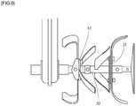
- central portions of two support plates 31, 32 which are outer and inner ones are fixed at a predetermined interval onto a tilling shaft 30 on one side with respect to the lateral direction, and a pair of tilling claws is fixed to each of an outside surface and an inside surface of each of the outer and inner support plates 31, 32 in such a manner that eight tilling claws in total are fixed with the phase shifted by 180 degrees.
- first-row tilling claws AIR, A2R which are the outermost are fixed with bolts to the outside surface of the support plate 31 with their distal ends being bent outward and with the phase shifted by 180 degrees.
- Second-row tilling claws B1L, B2L which are the second outermost are fixed with bolts to the inside surface of the support plate 31 with their distal ends being bent inward and with the phase shifted by 180 degrees.
- the tilling claws B1L, B2L are arranged with the phase shifted by 90 degrees relative to the first-row tilling claws AIR, A2R.
- Third-row tilling claws C1R, C2R which are the third outermost are fixed with bolts to the outside surface of the support plate 32 with their distal ends being bent outward and with the phase shifted by 180 degrees.
- the tilling claws C1R, C2R are arranged with the phase shifted by 45 degrees relative to the second-row tilling claws B1L, B2L.
- Fourth-row tilling claws D1L, D2L which are the fourth outermost are fixed with bolts to the inside surface of the support plate 32 with their distal ends being bent inward and with the phase shifted by 180 degrees.
- the tilling claws D1L, D2L are arranged with the phase shifted by 90 degrees relative to the third-row tilling claws C1R, C2R.
- the tilling claws are fixed respectively to the support plates 31, 32 such that the distal ends of the tilling claws protrude alternately leftward and rightward, and the tilling claws are fixed while being arranged with the phase shifted by 45 degrees so as not to overlap in a side view.
- the areas where the third-row tilling claws C1R and C2R which are the third outermost are placed are smaller than the areas where the other tilling claws are placed.
- the work volume of the third-row tilling claws C1R, C2R which are the third outermost is smaller.
- the wear of the third-row tilling claws C1R, C2R which are the third outermost is smaller, and different from the wear of the other tilling claws, which causes a variation in the time for replacement.
- a large torque variation occurs in the work, and thus the behavior is unstable.
- the tilling claws are attached such that they are bent alternately leftward and rightward on the respective support plates 31, 32.
- the bending direction of the tilling claws is AIR (right) ⁇ D1L (left) ⁇ B1L (left) ⁇ C1R (right) ⁇ A2R (right) ⁇ D2L (left) ⁇ B2L (left) ⁇ C2R (right) ⁇ AIR (right) in this order starting from the tilling claw AIR. That is, the tilling claws are not always placed so as to be bent alternately leftward and rightward. Thus, the lateral swing is not stabilized, which causes vibrations.
- a tilling apparatus of a husbandry machine includes: a tilling shaft that horizontally extends in a direction perpendicular to a traveling direction of a machine body, the tilling shaft being coupled to a driving unit and rotationally driven by the driving unit; a plurality of support members fixed onto the tilling shaft, and including a first support member, a second support member, and a third support member arranged in this order from the machine body outer side to the machine body inner side; and a pair of tilling claw s attached to each of the plurality of support members so as to be oriented toward the machine body outer side or the machine body inner side, the pair of tilling claws being arranged with the phase shifted by 180 degrees in a side view, wherein four rows each including the pair of tilling claws are provided such that first-row tilling claws, second-row tilling claws, third-row tilling claws, and fourth-row tilling claws are arranged in this order from the machine body outer side to the inner side, with the phase shifted
- the second support member includes a first flange to which the one tilling claw of the second-row tilling claws is attached and a second flange to which the other tilling claw of the third-row tilling claws is attached; and the first flange and the second flange are fixed to the tilling shaft with the phase shifted by 45 degrees in a side view.
- the tilling shaft is separable at a middle position with respect to the axial direction thereof, the separation being made with the first support member and the first flange integrated.
- the tilling apparatus of the husbandry machine allows the plurality of tilling claws attached to the tilling shaft to be worn substantially evenly, which can make the claws long-lasting.
- a torque variation is small, and thus an efficient use of the engine horsepower is enabled, so that the fuel consumption can be improved.
- the behavior is stabilized, and fatigue of a work operator can be reduced.
- the husbandry machine 1 is capable of power transmission by a configuration in which: an engine 3 is mounted on a machine body frame 2; a transmission case 4 stands at the rear of the engine 3 and in a central region of the machine body frame 2 with respect to a lateral (left-right) direction; and a transfer case 5 is arranged between the engine 3 and a region above the transmission case 4.
- a tilling shaft 6 is horizontally laid in the laterally direction, and in other words, the tilling shaft 6 is disposed perpendicularly to the F direction which is a traveling direction, and onto the tilling shaft 6, tilling claws 7, 7, ... are fixed in a radial fashion, to constitute the tilling apparatus 10.
- a proximal portion of the steering part 8 is secured to an upper portion of the transmission case 4.
- the steering part 8 protrudes obliquely upward to the rear, and the steering part 8 has, in a rear portion thereof, a grip in which a clutch lever, an acceleration lever, and the like, are arranged.
- a fuel tank 9 is disposed above the engine 3. Behind the machine body frame 2, a resistance rod 11 is attached with its vertical height adjustable.
- the tilling apparatus 10 which is a principal part of the present invention will be detailed.
- the tilling apparatus 10 is laterally symmetric, and thus a right part thereof will be described.
- an output shaft 12 horizontally protrudes in the lateral direction from a lower side surface of the transmission case 4, and laterally one end of the tilling shaft 6 is fixed to the output shaft 12.
- the tilling claws 7, 7, ... are secured onto the tilling shaft 6 with interposition of a support part 20, and a gauge wheel 14 is fixed to the laterally other end of the tilling shaft 6.
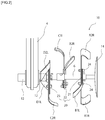
- the support part 20 includes a first support member 21, a second support member 22, and a third support member 23, which are arranged on the tilling shaft 6 in parallel and at predetermined intervals sequentially from the outer side.
- Each of the first support member 21 and the third support member 23 has three tilling claws 7, 7, 7 attached, and the second support member 22 has two tilling claws 7, 7 attached.
- eight tilling claws 7, 7, ... are attached onto the tilling shaft 6 on one side with respect to the lateral direction, with the phase shifted by 45 degrees in a side view.
- the first support member 21 is formed of a substantially square plate member, whose central portion is fixed to the tilling shaft 6, and fixing holes 21a, 21a, ... are opened respectively in the four vertexes (corner portions) on the outer periphery of the first support member 21.
- the fixing holes 21a, 21a, ... are arranged with the phase shifted by 90 degrees about the shaft center of the tilling shaft 6.
- Fixing holes which are opened in a proximal portion of the tilling claw 7 are positioned to two adjacent fixing holes 21a, 21a, and fixed with bolts 24, 24.
- how to fix is not limited, and the fixing may be made by using, for example, pins.
- the second support member 22 has two plate members (first flange 22a, second flange 22b), and each of the plate members has the same configuration as that of the first support member 21.
- the third support member 23 also has the same configuration as that of the first support member 21, and thus descriptions of their configurations are omitted.
- the tilling claws 7 are claws having machete-like shapes, with their distal ends being bent rightward or leftward. That is, there are two types of the tilling claws 7, namely, the type bent rightward and the type bent leftward, and the number of each type of tilling claws 7 arranged on the tilling shaft 6 is the same.
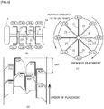
- An arranging configuration (arrangement) of the tilling claws 7, 7, ... will be described with FIG. 3, FIG. 4 , and FIG. 5 . From the right side, the first row is defined as A, the second row is defined as B, the third row is defined as C, and the fourth row is defined as D.
- Two tilling claws included in the same row are sequentially numbered 1, 2.
- a tilling claw whose distal end is bent rightward is labeled R
- a tilling claw whose distal end is bent leftward is labeled L.
- the tilling claw AIR and the tilling claw A2R included in the first row are attached to one side surface (in this embodiment, a left side surface) of the first support member 21 with the bolts 24, 24, 24, 24 with the phase shifted by 180 degrees.
- the tilling claw B1L included in the second row whose distal end is bent inward (leftward), is attached to the other side surface of the first support member 21 at a location between the tilling claw AIR and the tilling claw A2R, with the bolts 24, 24 with the phase shifted by 90 degrees.
- the second support member 22 (the first flange 22a and the second flange 22b) are fixed onto the tilling shaft 6, and the tilling claw B2R whose distal end is bent outward (rightward) is fixed to the outer first flange 22a with bolts with the phase shifted by 180 degrees relative to the tilling claw B1L included in the second row.
- the first flange 22a is arranged on the tilling shaft 6 such that its fixing holes have the same phase as the phase of the fixing holes 21a of the first support member 21.
- the second flange 22b is arranged with the phase shifted by 45 degrees relative to the first flange 22a about the tilling shaft 6. In this manner, the tilling claw C1L included in the third row, whose distal end is bent inward (leftward), is attached to the second flange 22b with the phase shifted by 45 degrees relative to the tilling claw B2R.
- the third support member 23 is fixed onto the tilling shaft 6, and the tilling claw C2R included in the third row, whose distal end is bent outward (rightward), is fixed to one side surface of the third support member 23 with bolts with the phase shifted by 180 degrees relative to the tilling claw C1L.
- the tilling claws D1L, D2L included in the fourth row, whose distal ends are bent inward (leftward), are fixed to the other side surface of the third support member 23 with bolts with the phase shifted by 90 degrees relative to the tilling claw C2R.
- the tilling claw D1L and the tilling claw D2L are fixed with the phase shifted by 180 degrees.
- Fixing holes of the third support member 23 have the same phase as the phase of the fixing holes of the second flange 22b.
- the shape of the support part 20 is not limited to a square but may be a circle, as long as the fixing holes are phase-shifted by 90 degrees (or 45 degrees) around a concentric circle.
- the tilling apparatus 10 having such a configuration performs a tilling work, as shown in FIG. 5(b) , the areas where the respective tilling claws 7, 7, ... are placed are substantially equal, so that their respective work volumes are substantially equal, which enables the work to be performed efficiently, and the tilling claws 7, 7, ... are worn evenly. As shown in FIG. 5(b) , the areas where the respective tilling claws 7, 7, ... are placed are substantially equal, so that their respective work volumes are substantially equal, which enables the work to be performed efficiently, and the tilling claws 7, 7, ... are worn evenly. As shown in FIG.
- the leftward or rightward bending direction of the tilling claws 7 with respect to the order in which the tilling claws 7 are placed is AIR (right) ⁇ D1L (left) ⁇ B2R (right) ⁇ C1L (left) ⁇ A2R (right) ⁇ D2L (left) ⁇ B1L (left) ⁇ C2R (right) ⁇ AIR (right).
- the number of times of alternate placement of right and left is increased as compared with the conventional. In other words, the number of times of consecutive placement of right and right or left and left is reduced, so that a torque variation decreases, which can reduce vibrations and fatigue.
- the tilling claws 7, by being arranged, can provide the same effects as described above.
- FIG. 6(a) As for the arrangement of the tilling claws 7, there are a second embodiment shown in FIG. 6(a) , a third embodiment shown in FIG. 6(b) , and a fourth embodiment shown in FIG. 6(c) .
- eight tilling claws 7, 7, ... in total are arranged on the tilling shaft 6 at intervals of 45 degrees.
- the embodiments can make the placement areas substantially equal while being identical in terms of the number of tilling claws 7 attached to the first support member 21, the second support member 22, and the third support member 23, the leftward or rightward direction in which the distal ends are bent, and the phase (180 degrees) of attachment of the tilling claws 7 in each row while being different in terms of the angle of attachment in each support member 21, 22, 23, and the order of placement into a field plane.
- an arrangement is a laterally inverted version of the arrangement of the first embodiment.
- the first support member 21 and the first flange 22a of the second support member 22 are rotated clockwise by 90 degrees relative to the third support member 23 and the second flange 22b of the second support member 22, and fixed.
- the arrangement is made such that the tilling claws 7 are placed in the order of D1L ⁇ A1R ⁇ C1L ⁇ B2R ⁇ D2L ⁇ A2R ⁇ C2R ⁇ B1L ⁇ D1L.
- the tilling claw B1L and the tilling claw B2R are attached are shifted by 180 degrees relative to the first embodiment. Therefore, as compared with the state of the first embodiment, the tilling claw B1L is attached on the first support member 21 with the phase shifted by 180 degrees, and the tilling claw B2R is attached on the second support member 22 with the phase shifted by 180 degrees. In this manner, the arrangement is made such that the tilling claws 7 are placed in the order of A1R ⁇ D1L ⁇ B1L ⁇ C1L ⁇ A2R ⁇ D2L ⁇ B2R ⁇ C2R ⁇ A1R.
- an arrangement is a laterally inverted version of the arrangement of the third embodiment.
- the positions where the tilling claw B1L and the tilling claw B2R are attached are shifted by 180 degrees.
- the arrangement is made such that the tilling claws 7 are placed in the order of D1L ⁇ A1R ⁇ C1L ⁇ B1L ⁇ D2L ⁇ A2R ⁇ C2R ⁇ B2R ⁇ D1L.
- the tilling shaft 6 is separable in the lateral direction, and capable of an intertillage work by removing an outside part. That is, the tilling shaft 6 is separable into an outside tilling shaft 6a and an inside tilling shaft 6b, and the inner end of the inside tilling shaft 6b is fixed to the output shaft 12 of the transmission case 4 while the inner end of the outside tilling shaft 6a is inserted into the outer end of the inside tilling shaft 6b such that they can be fixed while being fitted to each other with a pin 25.
- how to fix is not limited, and the fixing may be made by using, for example, a bolt.
- the first support member 21 is fixed onto the outer end of the outside tilling shaft 6a, and the tilling claws AIR, A2R, B1L are attached onto the first support member 21 in the above-described manner.
- the first flange 22a of the second support member 22 is fixed onto the inner end of the outside tilling shaft 6a, and the tilling claw B2R is fixed onto the first flange 22a.
- the second flange 22b is fixed onto the outer end of the inside tilling shaft 6b, and the tilling claw C1L is attached onto the second flange 22b in the above-described manner.
- the third support member 23 is fixed onto the inner end of the inside tilling shaft 6b, and the tilling claws C2R, D1L, D2L are fixed in the above-described manner.
- the tilling apparatus 10 includes: the tilling shaft 6 that horizontally extends in a direction perpendicular to the traveling direction of the machine body, the tilling shaft 6 being coupled to the engine 3 serving as a driving unit and rotationally driven by the driving unit; the first support member 21, the second support member 22, and the third support member 23 fixed onto the tilling shaft 6, and arranged in this order from the outer side with respect to the lateral direction of the machine body; and four pairs of tilling claws 7, 7, ... provided in each of left and right parts of the tilling apparatus 10, the pairs of tilling claws 7, 7, ... being attached to the support member 21, 22, 23 so as to be oriented toward the outer side or the inner side, each of the pairs of tilling claws 7, 7, ...
- the amounts by which the plurality of tilling claws 7, 7, ... attached to the tilling shaft 6 function are substantially equal, and thus the wears of the respective tilling claws 7, 7, ... are also substantially equal, which can make the tilling claws 7 long-lasting.
- a torque variation is small, and thus an efficient use of the engine horsepower is enabled, so that the fuel consumption can be improved.
- the behavior is stabilized, and fatigue of a work operator can be reduced.
- the second support member 22 includes the first flange 22a to which the tilling claw (B2R) is attached and the second flange 22b to which the tilling claw (C1L) is attached, and the first flange 22a and the second flange 22b are fixed to the tilling shaft 6 with the phase shifted by 45 degrees in a side view. This makes it easy to divide the tilling apparatus 10 in the middle thereof, and four tilling claws 7 can be arranged in a balanced manner on each of the tilling shafts 6a, 6b obtained after separation.
- the tilling shaft 6 is separable at a middle position with respect to the axial direction thereof, the separation being made such that the first support member 21 and the first flange 22a are integrated while the second flange 22b and the third support member 23 are integrated. Accordingly, by separating the tilling shaft 6 and removing the outer parts thereof, the tilling width can be easily narrowed, and works in a furrow, etc. can be easily performed.
- the present invention is applicable to a tilling apparatus of a husbandry machine.
Landscapes
- Life Sciences & Earth Sciences (AREA)
- Engineering & Computer Science (AREA)
- Mechanical Engineering (AREA)
- Soil Sciences (AREA)
- Environmental Sciences (AREA)
- Soil Working Implements (AREA)
Applications Claiming Priority (2)
| Application Number | Priority Date | Filing Date | Title |
|---|---|---|---|
| JP2015178009A JP6648903B2 (ja) | 2015-09-09 | 2015-09-09 | 管理機の耕耘装置 |
| PCT/JP2016/068840 WO2017043153A1 (ja) | 2015-09-09 | 2016-06-24 | 管理機の耕耘装置 |
Publications (2)
| Publication Number | Publication Date |
|---|---|
| EP3348127A1 true EP3348127A1 (de) | 2018-07-18 |
| EP3348127A4 EP3348127A4 (de) | 2018-09-26 |
Family
ID=58239663
Family Applications (1)
| Application Number | Title | Priority Date | Filing Date |
|---|---|---|---|
| EP16844019.6A Withdrawn EP3348127A4 (de) | 2015-09-09 | 2016-06-24 | Bodenbearbeitungsvorrichtung einer ackerbaumaschine |
Country Status (4)
| Country | Link |
|---|---|
| EP (1) | EP3348127A4 (de) |
| JP (1) | JP6648903B2 (de) |
| KR (1) | KR102071153B1 (de) |
| WO (1) | WO2017043153A1 (de) |
Families Citing this family (2)
| Publication number | Priority date | Publication date | Assignee | Title |
|---|---|---|---|---|
| KR20200060125A (ko) | 2018-11-22 | 2020-05-29 | 주식회사 이안이엔지 | 경운 작업을 위한 궤도 차량 |
| KR102724128B1 (ko) * | 2024-03-18 | 2024-10-30 | 주식회사 삼원농기계 | 이중 로터리를 구비한 로터베이터 |
Family Cites Families (19)
| Publication number | Priority date | Publication date | Assignee | Title |
|---|---|---|---|---|
| JPS587501U (ja) * | 1981-07-07 | 1983-01-18 | 旭陽工業株式会 | 中耕除草ロ−タ |
| JPS61207104U (de) * | 1985-06-18 | 1986-12-27 | ||
| JPH0190303U (de) * | 1987-12-10 | 1989-06-14 | ||
| US5048616A (en) * | 1990-03-05 | 1991-09-17 | Hoffco, Inc. | Garden tiller tine assembly |
| JPH0633402U (ja) * | 1992-10-13 | 1994-05-06 | マメトラ農機株式会社 | 耕耘ロータ |
| JP2657747B2 (ja) * | 1992-12-28 | 1997-09-24 | 本田技研工業株式会社 | 耕耘機 |
| JPH0779602A (ja) * | 1993-09-14 | 1995-03-28 | Kanzaki Kokyukoki Mfg Co Ltd | ロータリー耕耘装置 |
| JP3420358B2 (ja) * | 1994-11-11 | 2003-06-23 | 本田技研工業株式会社 | 正逆転作業機 |
| JP3565937B2 (ja) * | 1995-03-13 | 2004-09-15 | 本田技研工業株式会社 | 同軸正逆転作業機 |
| JPH09182502A (ja) * | 1995-12-30 | 1997-07-15 | Shigeki Sano | 耕耘機の耕耘作業体 |
| JP2001320902A (ja) | 2000-05-17 | 2001-11-20 | Mitsubishi Agricult Mach Co Ltd | 歩行型移動農機 |
| JP2005237344A (ja) * | 2004-02-27 | 2005-09-08 | Iseki & Co Ltd | 歩行型耕耘機 |
| JP2005318819A (ja) * | 2004-05-07 | 2005-11-17 | Kobashi Kogyo Co Ltd | 耕耘装置 |
| WO2010100758A1 (ja) * | 2009-03-06 | 2010-09-10 | ヤンマー株式会社 | 耕耘爪及びこの耕耘爪を備えるロータリ |
| JP2010273579A (ja) * | 2009-05-27 | 2010-12-09 | Iseki & Co Ltd | 電動管理機 |
| ES2544633T3 (es) * | 2011-11-11 | 2015-09-02 | Kongskilde Industries A/S | Sistema de montaje rápido para montar una cuchilla en una máquina agrícola y máquina agrícola correspondiente |
| ITPD20120293A1 (it) * | 2012-10-09 | 2014-04-10 | Valentini Antonio S R L | Gruppo fresa per macchina zappatrice rotativa |
| ITPD20120324A1 (it) * | 2012-10-31 | 2014-05-01 | Valentini Antonio S R L | Gruppo fresa per macchina zappatrice rotativa |
| WO2015064291A1 (ja) * | 2013-10-31 | 2015-05-07 | ヤンマー株式会社 | ロータリ耕耘装置の草藁巻付防止構造 |
-
2015
- 2015-09-09 JP JP2015178009A patent/JP6648903B2/ja active Active
-
2016
- 2016-06-24 WO PCT/JP2016/068840 patent/WO2017043153A1/ja not_active Ceased
- 2016-06-24 KR KR1020187007957A patent/KR102071153B1/ko active Active
- 2016-06-24 EP EP16844019.6A patent/EP3348127A4/de not_active Withdrawn
Also Published As
| Publication number | Publication date |
|---|---|
| WO2017043153A1 (ja) | 2017-03-16 |
| JP6648903B2 (ja) | 2020-02-14 |
| JP2017051136A (ja) | 2017-03-16 |
| KR102071153B1 (ko) | 2020-01-29 |
| EP3348127A4 (de) | 2018-09-26 |
| KR20180042364A (ko) | 2018-04-25 |
Similar Documents
| Publication | Publication Date | Title |
|---|---|---|
| CN106061237B (zh) | 农用接地链条 | |
| CN110089274A (zh) | 用于农业系统的拉茎辊组件 | |
| JP6648903B2 (ja) | 管理機の耕耘装置 | |
| JP2017013759A (ja) | 水田作業機 | |
| CN110062576A (zh) | 作业车辆 | |
| US7331402B2 (en) | Device for attaching blades to rings connected to a rotating shaft for an agricultural machine | |
| JP6785688B2 (ja) | 作業車 | |
| US9506502B2 (en) | Elastic shaft coupling | |
| JP5168270B2 (ja) | ロータリ耕耘装置 | |
| JP4921735B2 (ja) | 一輪管理機の走行車輪 | |
| JP6240257B2 (ja) | 自転車の後輪クイックリリース構造 | |
| KR102376524B1 (ko) | 자전거용 농기구 | |
| CN104541706B (zh) | 手扶式行距可调插秧机的分插机构 | |
| JP2006262715A5 (de) | ||
| JP6815644B2 (ja) | 除草装置 | |
| JP2006262715A (ja) | 歩行型耕耘機 | |
| JP4474374B2 (ja) | 歩行型管理機 | |
| CN105409449A (zh) | 收割机 | |
| US2383282A (en) | Traction unit | |
| KR101916308B1 (ko) | 트랙터의 hst 트랜스미션 | |
| JP6066842B2 (ja) | 耕耘爪 | |
| JP2013013346A (ja) | 耕耘ロータ | |
| EP3000293B1 (de) | Kreiselegge mit verbesserter festigkeit | |
| JP6278393B2 (ja) | 除草機 | |
| JP5973339B2 (ja) | 歩行型管理機 |
Legal Events
| Date | Code | Title | Description |
|---|---|---|---|
| STAA | Information on the status of an ep patent application or granted ep patent |
Free format text: STATUS: THE INTERNATIONAL PUBLICATION HAS BEEN MADE |
|
| PUAI | Public reference made under article 153(3) epc to a published international application that has entered the european phase |
Free format text: ORIGINAL CODE: 0009012 |
|
| STAA | Information on the status of an ep patent application or granted ep patent |
Free format text: STATUS: REQUEST FOR EXAMINATION WAS MADE |
|
| 17P | Request for examination filed |
Effective date: 20180409 |
|
| AK | Designated contracting states |
Kind code of ref document: A1 Designated state(s): AL AT BE BG CH CY CZ DE DK EE ES FI FR GB GR HR HU IE IS IT LI LT LU LV MC MK MT NL NO PL PT RO RS SE SI SK SM TR |
|
| AX | Request for extension of the european patent |
Extension state: BA ME |
|
| A4 | Supplementary search report drawn up and despatched |
Effective date: 20180824 |
|
| RIC1 | Information provided on ipc code assigned before grant |
Ipc: A01B 33/08 20060101AFI20180820BHEP Ipc: A01B 33/02 20060101ALI20180820BHEP Ipc: A01B 33/12 20060101ALI20180820BHEP Ipc: A01B 33/10 20060101ALI20180820BHEP |
|
| DAV | Request for validation of the european patent (deleted) | ||
| DAX | Request for extension of the european patent (deleted) | ||
| STAA | Information on the status of an ep patent application or granted ep patent |
Free format text: STATUS: EXAMINATION IS IN PROGRESS |
|
| 17Q | First examination report despatched |
Effective date: 20200226 |
|
| RAP1 | Party data changed (applicant data changed or rights of an application transferred) |
Owner name: YANMAR POWER TECHNOLOGY CO., LTD. |
|
| GRAP | Despatch of communication of intention to grant a patent |
Free format text: ORIGINAL CODE: EPIDOSNIGR1 |
|
| STAA | Information on the status of an ep patent application or granted ep patent |
Free format text: STATUS: GRANT OF PATENT IS INTENDED |
|
| INTG | Intention to grant announced |
Effective date: 20210920 |
|
| STAA | Information on the status of an ep patent application or granted ep patent |
Free format text: STATUS: THE APPLICATION IS DEEMED TO BE WITHDRAWN |
|
| 18D | Application deemed to be withdrawn |
Effective date: 20220201 |