EP3348154A1 - Verbrennungsfreie aromainhalations- und zerstäubungseinheit - Google Patents
Verbrennungsfreie aromainhalations- und zerstäubungseinheit Download PDFInfo
- Publication number
- EP3348154A1 EP3348154A1 EP16851457.8A EP16851457A EP3348154A1 EP 3348154 A1 EP3348154 A1 EP 3348154A1 EP 16851457 A EP16851457 A EP 16851457A EP 3348154 A1 EP3348154 A1 EP 3348154A1
- Authority
- EP
- European Patent Office
- Prior art keywords
- heating element
- resistance heating
- aerosol source
- controller
- expressed
- Prior art date
- Legal status (The legal status is an assumption and is not a legal conclusion. Google has not performed a legal analysis and makes no representation as to the accuracy of the status listed.)
- Granted
Links
Images


Classifications
-
- A—HUMAN NECESSITIES
- A24—TOBACCO; CIGARS; CIGARETTES; SIMULATED SMOKING DEVICES; SMOKERS' REQUISITES
- A24F—SMOKERS' REQUISITES; MATCH BOXES; SIMULATED SMOKING DEVICES
- A24F40/00—Electrically operated smoking devices; Component parts thereof; Manufacture thereof; Maintenance or testing thereof; Charging means specially adapted therefor
- A24F40/50—Control or monitoring
- A24F40/53—Monitoring, e.g. fault detection
-
- A—HUMAN NECESSITIES
- A24—TOBACCO; CIGARS; CIGARETTES; SIMULATED SMOKING DEVICES; SMOKERS' REQUISITES
- A24B—MANUFACTURE OR PREPARATION OF TOBACCO FOR SMOKING OR CHEWING; TOBACCO; SNUFF
- A24B15/00—Chemical features or treatment of tobacco; Tobacco substitutes, e.g. in liquid form
- A24B15/10—Chemical features of tobacco products or tobacco substitutes
- A24B15/16—Chemical features of tobacco products or tobacco substitutes of tobacco substitutes
- A24B15/167—Chemical features of tobacco products or tobacco substitutes of tobacco substitutes in liquid or vaporisable form, e.g. liquid compositions for electronic cigarettes
-
- A—HUMAN NECESSITIES
- A24—TOBACCO; CIGARS; CIGARETTES; SIMULATED SMOKING DEVICES; SMOKERS' REQUISITES
- A24B—MANUFACTURE OR PREPARATION OF TOBACCO FOR SMOKING OR CHEWING; TOBACCO; SNUFF
- A24B15/00—Chemical features or treatment of tobacco; Tobacco substitutes, e.g. in liquid form
- A24B15/18—Treatment of tobacco products or tobacco substitutes
-
- A—HUMAN NECESSITIES
- A24—TOBACCO; CIGARS; CIGARETTES; SIMULATED SMOKING DEVICES; SMOKERS' REQUISITES
- A24F—SMOKERS' REQUISITES; MATCH BOXES; SIMULATED SMOKING DEVICES
- A24F40/00—Electrically operated smoking devices; Component parts thereof; Manufacture thereof; Maintenance or testing thereof; Charging means specially adapted therefor
- A24F40/40—Constructional details, e.g. connection of cartridges and battery parts
- A24F40/42—Cartridges or containers for inhalable precursors
-
- A—HUMAN NECESSITIES
- A24—TOBACCO; CIGARS; CIGARETTES; SIMULATED SMOKING DEVICES; SMOKERS' REQUISITES
- A24F—SMOKERS' REQUISITES; MATCH BOXES; SIMULATED SMOKING DEVICES
- A24F40/00—Electrically operated smoking devices; Component parts thereof; Manufacture thereof; Maintenance or testing thereof; Charging means specially adapted therefor
- A24F40/50—Control or monitoring
- A24F40/51—Arrangement of sensors
-
- A—HUMAN NECESSITIES
- A24—TOBACCO; CIGARS; CIGARETTES; SIMULATED SMOKING DEVICES; SMOKERS' REQUISITES
- A24F—SMOKERS' REQUISITES; MATCH BOXES; SIMULATED SMOKING DEVICES
- A24F40/00—Electrically operated smoking devices; Component parts thereof; Manufacture thereof; Maintenance or testing thereof; Charging means specially adapted therefor
- A24F40/50—Control or monitoring
- A24F40/57—Temperature control
-
- A—HUMAN NECESSITIES
- A24—TOBACCO; CIGARS; CIGARETTES; SIMULATED SMOKING DEVICES; SMOKERS' REQUISITES
- A24F—SMOKERS' REQUISITES; MATCH BOXES; SIMULATED SMOKING DEVICES
- A24F40/00—Electrically operated smoking devices; Component parts thereof; Manufacture thereof; Maintenance or testing thereof; Charging means specially adapted therefor
- A24F40/65—Devices with integrated communication means, e.g. wireless communication means
-
- H—ELECTRICITY
- H05—ELECTRIC TECHNIQUES NOT OTHERWISE PROVIDED FOR
- H05B—ELECTRIC HEATING; ELECTRIC LIGHT SOURCES NOT OTHERWISE PROVIDED FOR; CIRCUIT ARRANGEMENTS FOR ELECTRIC LIGHT SOURCES, IN GENERAL
- H05B3/00—Ohmic-resistance heating
- H05B3/40—Heating elements having the shape of rods or tubes
- H05B3/42—Heating elements having the shape of rods or tubes non-flexible
- H05B3/44—Heating elements having the shape of rods or tubes non-flexible heating conductor arranged within rods or tubes of insulating material
-
- A—HUMAN NECESSITIES
- A24—TOBACCO; CIGARS; CIGARETTES; SIMULATED SMOKING DEVICES; SMOKERS' REQUISITES
- A24F—SMOKERS' REQUISITES; MATCH BOXES; SIMULATED SMOKING DEVICES
- A24F40/00—Electrically operated smoking devices; Component parts thereof; Manufacture thereof; Maintenance or testing thereof; Charging means specially adapted therefor
- A24F40/10—Devices using liquid inhalable precursors
-
- A—HUMAN NECESSITIES
- A24—TOBACCO; CIGARS; CIGARETTES; SIMULATED SMOKING DEVICES; SMOKERS' REQUISITES
- A24F—SMOKERS' REQUISITES; MATCH BOXES; SIMULATED SMOKING DEVICES
- A24F40/00—Electrically operated smoking devices; Component parts thereof; Manufacture thereof; Maintenance or testing thereof; Charging means specially adapted therefor
- A24F40/20—Devices using solid inhalable precursors
Definitions
- the present invention relates to a non-burning type flavor inhaler including a resistance heating element configured to atomize an aerosol source by resistance electric heating, and also relates to an atomizing unit.
- the non-burning type flavor inhaler includes a heater configured to atomize an aerosol source without burning (for example, Patent Literature 1).
- Patent Literature 1 a non-burning type flavor inhaler
- Patent Literature 2 proposes a technique for always monitoring a temperature of a heater and estimating an amount of the aerosol source consumed during a puff action, based on a relation between the temperature of a heater and a vaporization rate of the aerosol source (for example, Patent Literature 2).
- a second feature according to the first feature is summarized as that the non-burning type flavor inhaler comprising: an information source including the specific parameter or identification information associated with the specific parameter, wherein the controller is configured to calculate the L, based on information included in the information source.
- a third feature according to the second feature is summarized as that the non-burning type flavor inhaler comprising: a control unit including the controller, wherein the atomizing unit includes the information source, in addition to the aerosol source and the resistance heating element.
- a fourth feature according to any one of the first to third features is summarized as that the atomizing unit includes a holding member configured to hold the aerosol source, in addition to the aerosol source and the resistance heating element,
- a fifth feature according to any one of the first to fourth features is summarized as that a temperature coefficient ⁇ of a resistance value of the resistance heating element is 0.8 x 10 -3 [°C -1 ] or less.
- a sixth feature according to any one of the first to fourth features is summarized as that a temperature coefficient ⁇ of a resistance value of the resistance heating element is 0.4 x 10 -3 [°C -1 ] or less.
- a seventh feature according to any one of the first to sixth features is summarized as the non-burning type flavor inhaler comprising: a battery configured to accumulate power supplied to the resistance heating element, wherein an output voltage value of the battery is expressed by V A , a reference voltage value of the battery is expressed by V C , a correction term of the E is expressed by D, and the controller is configured to calculate the D based on the V A and the V C , and is configured to calculate the E based on the D or configured to control the E based on the D.
- a ninth feature according to the seventh feature or the eighth feature is summarized as that the controller is configured to control the power amount supplied to the resistance heating element, according to a power amount corrected based on the D.
- a tenth feature according to any one of the first to ninth features is summarized as the non-burning type flavor inhaler comprising: an information source including a resistance value of the resistance heating element or identification information associated with the resistance value of the resistance heating element, wherein the controller is configured to calculate the E, based on the information included in the information source.
- a twelfth feature according to the eleventh feature is summarized as that the controller uses a predetermined value T 0 as T, if controlling the E.
- a fourteenth feature according to any one of the first to twelfth features is summarized as that an upper limit threshold value of the power amount supplied to the resistance heating element during one puff action is expressed by E MAX , and the controller is configured to control the power amount supplied to the resistance heating element so that the E does not exceed the E MAX .
- a sixteenth feature according to the fourteenth feature is summarized as the non-burning type flavor inhaler comprising: an information source including the specific parameter or identification information associated with the specific parameter, wherein the specific parameter includes information for specifying the E MAX .
- a seventeenth feature according to the fourteenth feature is summarized as the non-burning type flavor inhaler comprising: an information source including the specific parameter or identification information associated with the specific parameter, wherein the specific parameter includes information for specifying the E MIN .
- controller is configured to estimate a remaining amount of the aerosol source, based on the L.
- a nineteenth feature according to the eighteenth feature is summarized as the non-burning type flavor inhaler comprising: an information source including remaining amount information indicating the remaining amount of the aerosol source or identification information associated with the remaining amount information.
- a twentieth feature according to the eighteenth feature or the nineteenth feature is summarized as that if the remaining amount of the aerosol source falls below a threshold value, the controller is configured to prohibit power supply to the resistance heating element or configured to notify a user that the remaining amount of the aerosol source falls below the threshold value.
- a twenty-first feature according to the twentieth feature is summarized as that if the remaining amount information cannot be acquired, the controller is configured to prohibit the power supply to the resistance heating element or configured to notify a user that the remaining amount information cannot be acquired.
- Patent Literature 1 it is necessary always to monitor the temperature of the heater to estimate the amount of the aerosol source consumed by a puff action.
- the temperature of the heater can be detected by using a temperature sensor or calculated by using a resistor provided separately from the heater.
- an additional component for monitoring the temperature of the heater is necessary, and thus, an increase in cost and size of the non-burning type flavor inhaler ensues.
- E denotes the power amount supplied to the resistance heating element during one puff action
- a and b denote specific parameters of the atomizing unit
- L denotes an amount of the aerosol source consumed during one puff action.
- Fig. 1 is a diagram illustrating a non-combustion type flavor inhaler 100 according to the embodiment.
- the non-combustion type flavor inhaler 100 is an instrument configured to suck a flavor component without combustion, and has a shape extending in a predetermined direction A which is a direction from a non-mouthpiece end to a mouthpiece end.
- Fig. 2 is a diagram illustrating an atomizing unit 111 according to the embodiment.
- the non-combustion type flavor inhaler 100 is simply referred to as a flavor inhaler 100.
- the flavor inhaler 100 includes an inhaler main body 110 and a cartridge 130.
- the inhaler main body 110 forms the main body of the flavor inhaler 100, and has a shape connectable to the cartridge 130. Specifically, the inhaler main body 110 has a tubular body 110X, and the cartridge 130 is connected to the mouthpiece end of the tubular body 110X.
- the inhaler main body 110 includes the atomizing unit 111 which atomizes an aerosol source without combustion and an electrical unit 112.
- the atomizing unit 111 includes a tubular body 111X that forms a part of the tubular body 110X. As illustrated in Fig. 2 , the atomizing unit 111 includes a reservoir 111P, a wick 111Q, and a resistance heating element 111R. The reservoir 111P, the wick 111Q, and the resistance heating element 111R are housed in the tubular body 111X.
- the reservoir 111P stores the aerosol source.
- the reservoir 111P is a porous body made of a material such as a resin web.
- the wick 111Q is an example of a holding member that holds the aerosol source supplied from the reservoir 111P.
- the wick 111Q is made of glass fibers.
- the resistance heating element 111R atomizes the aerosol source sucked up by the wick 111Q.
- the resistance heating element 111R is configured using, for example, a resistive heating element (for example, a heating wire) wound around the wick 111Q at a predetermined pitch.
- the resistance heating element 111R is a resistance heating element configured to atomize the aerosol source by resistance electric heating.
- R (T) is a resistance value at a temperature Temp
- R 0 is a resistance value at a temperature Temp 0
- ⁇ is a temperature coefficient.
- the temperature coefficient ⁇ varies depending on the temperature Temp, but can be approximately a constant under manufacturing and using conditions of the flavor inhaler 100 according to the embodiment.
- the temperature coefficient ⁇ of the resistance value of the resistance heating element 111R be a value that allows a change in the resistance value between a measurement temperature and a use temperature to fall within a predetermined range.
- the measurement temperature is a temperature of the resistance heating element 111R at the time of measuring the resistance value of the resistance heating element 111R in manufacturing the flavor inhaler 100.
- the measurement temperature is preferably lower than the use temperature of the resistance heating element 111R. Further, the measurement temperature is preferably a normal temperature (in a range of 20°C ⁇ 15°C).
- the use temperature is a temperature of the resistance heating element 111R at the time of using the flavor inhaler 100 and is in a range of 100°C to 400°C.
- any temperature coefficient ⁇ can be set, and the coefficient is, but not limited to, preferably 0.8 x 10 -3 [°C -1 ] or less, for example.
- the temperature coefficient ⁇ is preferably 0.4 x 10 -3 [°C -1 ] or less, for example.
- the temperature coefficient ⁇ is strongly affected by a composition of the resistance heating element.
- the resistance heater is preferably an alloy.
- the temperature coefficient ⁇ can be changed by adjusting the content ratio of elements contained in the alloy. By searching materials and designing with the above point of view, a substance having a different temperature coefficient ⁇ can be obtained.
- the embodiment uses a resistance heater that is made of an alloy (nichrome) of nickel and chromium, and has a temperature coefficient ⁇ of 0.4 x 10 -3 [°C -1 ] or less.
- the aerosol source is a liquid such as glycerin or propylene glycol.
- the aerosol source is held, for example, by the porous body made of the material such as the resin web as described above.
- the porous body may be made of a non-tobacco material or may be made of a tobacco material.
- the aerosol source may include a flavor source containing a nicotine component or the like.
- the aerosol source does not necessarily include the flavor source containing the nicotine component or the like.
- the aerosol source may include a flavor source containing components other than the nicotine component.
- the aerosol source does not necessarily include the flavor source containing components other than the nicotine component.
- the electrical unit 112 has a tubular body 112X that forms a part of the tubular body 110X.
- the electrical unit 112 includes a battery accumulating power to drive the flavor inhaler 100 and a control circuit to control the flavor inhaler 100.
- the battery and the control circuit are housed in the tubular body 112X.
- the battery is, for example, a lithium-ion battery.
- the control circuit is configured of, for example, a CPU and a memory. Details of the control circuit will be described later (see Fig. 3 ).
- the electrical unit 112 includes a vent hole 112A. As illustrated in Fig. 2 , air introduced from the vent hole 112A is guided to the atomizing unit 111 (the resistance heating element 111R).
- the cartridge 130 is configured to be connectable to the inhaler main body 110 forming the flavor inhaler 100.
- the cartridge 130 is provided to be closer to the mouthpiece side than the atomizing unit 111 on a flow path of a gas (hereinafter, air) sucked from the mouthpiece.
- a gas hereinafter, air
- the cartridge 130 is not necessarily provided to be closer to the mouthpiece side than the atomizing unit 111 in terms of a physical space, but may be provided to be closer to the mouthpiece side than the atomizing unit 111 on an aerosol flow path guiding the aerosol generated from the atomizing unit 111 to the mouthpiece side.
- the cartridge 130 includes a cartridge main body 131, a flavor source 132, a mesh 133A, and a filter 133B.
- the cartridge main body 131 has a tubular shape extending in the predetermined direction A.
- the cartridge main body 131 houses the flavor source 132.
- the flavor source 132 is provided to be closer to the mouthpiece side than the atomizing unit 111 on the flow path of the air sucked from the mouthpiece.
- the flavor source 132 gives the flavor component to the aerosol generated from the aerosol source. In other words, the flavor imparted to the aerosol by the flavor source 132 is conveyed to the mouthpiece.
- the flavor source 132 is configured using a raw material piece that gives the flavor component to the aerosol generated from the atomizing unit 111.
- the size of the raw material piece is preferably 0.2 mm or more and 1.2 mm or less. Further, the size of the raw material piece is preferably 0.2 mm or more and 0.7 mm or less. As the size of the raw material piece forming the flavor source 132 decreases, its specific surface area increases, and therefore the flavor component is easily released from the raw material pieces forming the flavor source 132. Accordingly, it is possible to suppress the amount of the raw material piece when giving a desired amount of the flavoring component to the aerosol.
- a shredded tobacco or a molded body obtained by molding a tobacco raw material into a granular shape can be used as the raw material piece forming the flavor source 132.
- the flavor source 132 may be a molded body obtained by molding the tobacco raw material into a sheet shape.
- the raw material piece forming the flavor source 132 may be made of plants (for example, mint, herbs, or the like) other than the tobacco.
- a flavor such as menthol may be given to the flavor source 132.
- the raw material piece forming the flavor source 132 is obtained by sieving according to JIS Z 8815, for example, using a stainless sieve according to JIS Z 8801.
- raw material pieces are sieved for 20 minutes by a dry type mechanical shaking method using a stainless sieve having a mesh size of 0.71 mm, thereby obtaining raw material pieces passing through the stainless sieve having the mesh size of 0.71 mm.
- the raw material pieces are sieved for 20 minutes by the dry type mechanical shaking method using a stainless steel sieve having a mesh size of 0.212 mm, thereby removing raw material pieces passing through the stainless sieve having the mesh size of 0.212 mm.
- the lower limit of the size of the raw material piece forming the flavor source 132 is defined by the mesh size of the stainless sieve defining the lower limit in the embodiment.
- an upper limit of the size of the raw material piece forming the flavor source 132 is defined by the mesh size of the stainless sieve defining the upper limit.
- the flavor source 132 is a tobacco source.
- the tobacco source may be a one including a basic substance.
- pH of an aqueous solution including the tobacco source and water of 10 times weight ratio is preferably greater than 7, and more preferably 8 or more. Accordingly, it is possible to efficiently take out the flavor component generated from the tobacco source by the aerosol. Accordingly, it is possible to suppress the amount of the tobacco source when giving the desired amount of the flavoring component to the aerosol.
- the pH of the aqueous solution including the tobacco source and water of 10 times weight ratio is preferably 14 or less, and more preferably 10 or less. Accordingly, it is possible to suppress damage (such as corrosion) to the flavor inhaler 100 (for example, the cartridge 130 or the inhaler main body 110).
- the flavor component generated from the flavor source 132 is conveyed by the aerosol, and it is unnecessary to heat the flavor source 132 itself.
- the mesh 133A is provided so as to close an opening of the cartridge main body 131 on the non-mouthpiece side with respect to the flavor source 132
- the filter 133B is provided so as to close an opening of the cartridge main body 131 on the mouthpiece side with respect to the flavor source 132.
- the mesh 133A has a roughness of a degree that prevents passage of the raw material piece forming the flavor source 132.
- the roughness of the mesh 133A has a mesh size of, for example, 0.077 mm or more and 0.198 mm or less.
- the filter 133B is made of a substance having air permeability.
- the filter 133B is preferably an acetate filter, for example.
- the filter 133B has a roughness of a degree that prevents passage of the raw material piece forming the flavor source 132.
- FIG. 3 is a diagram illustrating the block configuration of the non-combustion type flavor inhaler 100 according to the embodiment.
- the above-described atomizing unit 111 includes a memory 111M in addition to the resistance heating element 111R, etc.
- the control circuit 50 provided in the electrical unit 112 described above includes a controller 51.
- the control circuit 50 is an example of a control unit which includes a controller configured to control a power amount supplied to the resistance heating element 111R.
- the memory 111M is an example of an information source which has a specific parameter of the atomizing unit 111 (the wick 111Q, the resistance heating element 111R, etc.) or identification information associated with the specific parameter.
- the memory 111M stores the specific parameter of the atomizing unit 111.
- the memory 111M may store the resistance value of the resistance heating element 111R or identification information associated with the resistance value of the resistance heating element 111R. In the embodiment, the memory 111M stores the resistance value of the resistance heating element 111R.
- the memory 111M may store remaining amount information indicating the remaining amount of the aerosol source retained in the reservoir 111P or identification information associated with the remaining amount information. In the embodiment, the memory 111M stores the remaining amount information.
- the resistance value of the resistance heating element 111R may be an actually measured value of the resistance value or an estimated value of the resistance value. Specifically, when the resistance value of the resistance heating element 111R is measured by connecting terminals of a measurement device to both ends of the resistance heating element 111R, it is possible to use the actually measured value as the resistance value of the resistance heating element 111R. Alternatively, it is necessary to consider a resistance value of a part (such as an electrode) other than the resistance heating element 111R when the resistance value of the resistance heating element 111R is measured by connecting a terminal of a measurement device to an electrode connected to the resistance heating element 111R in a state where the electrode for connection with the power source provided in the flavor inhaler 100 is connected to the resistance heating element 111R. In such a case, it is preferable to use an estimated value in consideration of the resistance value of the part (such as the electrode) other than the resistance heating element 111R as the resistance value of the resistance heating element 111R.
- a magnitude of the power amount supplied to the resistance heating element 111R is defined by a value of a voltage to be applied to the resistance heating element 111R and a time during which the voltage is applied to the resistance heating element 111R. For example, in a case where the voltage is continuously applied to the resistance heating element 111R, the magnitude of the power amount supplied to the resistance heating element 111R is changed depending on a change in the value of the voltage to be applied to the resistance heating element 111R.
- the magnitude of the power amount supplied to the resistance heating element 111R is changed depending on a change in the value of the voltage to be applied to the resistance heating element 111R or a duty ratio (that is, a pulse width and a pulse interval).
- the controller 51 controls the power amount supplied to the resistance heating element 111R.
- E the power amount supplied to the resistance heating element 111R during one puff action a
- b specific parameters of the atomizing unit 111
- L the amount of the aerosol source consumed during one puff action
- E and L have a linear relationship and such a linear relationship differs for each atomizing unit 111.
- a vertical axis is L [mg/puff]
- E [J/puff] a horizontal axis
- E and L have the linear relationship if E is within the range from E MIN (A) to E MAX (A), and specific parameters of the atomizing unit A are a A and b A .
- E and L have the linear relationship if E is within the range from E MIN (B) to E MAX (B), and specific parameters of the atomizing unit B are a B and b B .
- the parameters a, b that define the linear relationship between E and L differ for each atomizing unit 111, and thus, are specific parameters of the atomizing unit 111.
- parameters E MIN and E MAX that define a range in which E and L have the linear relationship also differ for each atomizing unit 111, and thus, can be considered as specific parameters of the atomizing unit 111.
- the specific parameters of the atomizing unit 111 depend on a composition of the wick 111Q, a composition of the resistance heating element 111R, a composition of the aerosol source, a structure of the atomizing unit 111 (the wick 111Q and the resistance heating element 111R), and the like. Therefore, it should be noted that the specific parameters differ for each atomizing unit 111.
- the above-described memory 111M may store, in addition to the parameters a, b, the parameters E MIN and E MAX or identification information associated with these specific parameters.
- E is affected by a voltage Vs to be applied to the resistance heating element 111R and an application time T of the voltage Vs, and thus, E MIN and E MAX may be specified by the voltage Vs, T MIN , and T MAX .
- the above-described memory 111M may store, in addition to the parameters a, b, the parameters voltage Vs, T MIN , and T MAX or identification information associated with these specific parameters.
- the voltage Vs is a parameter used for replacing E MIN and E MAX with T MIN and T MAX , and may be a constant value. If the voltage Vs is a constant value, the voltage Vs may not need to be stored in the memory 111M. In the embodiment, the voltage Vs corresponds to a reference voltage value Vc described later, and the memory 111M stores the parameters T MIN and T MAX .
- the controller 51 estimates, based on L, the remaining amount (mg) of the aerosol source. Specifically, the controller 51 calculates L (mg) for each puff action, subtracts L from the remaining amount of the aerosol source indicated by the remaining amount information stored in the memory 111M, and updates the remaining amount information stored in the memory 111M.
- the controller 51 may prohibit the power supply to the resistance heating element 111R or may notify a user that the remaining amount of the aerosol source falls below the threshold value. If not possible to acquire the remaining amount information, the controller 51 may prohibit the power supply to the resistance heating element 111R or may notify the user that the remaining amount information cannot be acquired.
- the notification to the user may be performed by light emission of a light-emitting element provided in the flavor inhaler 100, for example.
- E A the power amount in a case where V A is applied to the resistance heating element 111R
- V A the output voltage value of a battery T: time during which voltage is applied to the resistance heating element 111R R: a resistance value of the resistance heating element 111R
- V A and T are values detectable by the controller 51
- R is a value acquirable by the controller 51 as a result of reading out from the memory 111M. Note that, R may be estimated by the controller 51.
- the controller 51 preferably corrects the above-described E, based on a correction term D.
- D is calculated based on the output voltage value V A of the battery and the reference voltage value V C of the battery.
- V C is a value predetermined depending on a type, etc. of the battery, and is a voltage higher than at least a final voltage of the battery. If the battery is a lithium-ion battery, the reference voltage value V C can be 3.2 V, for example.
- a level of the power amount supplied to the resistance heating element 111R can be set in a plurality of levels, that is, in a case where the flavor inhaler 100 has a plurality of modes having different amount of aerosol generated during one puff action, a plurality of reference voltage values V C may be set.
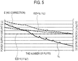
- the output voltage value V A of the battery decreases along with an increase in the number of times of puff actions (hereinafter, the number of puffs). Therefore, upon E not being corrected by D, even if the voltage application time T is assumed to be constant, E also decreases along with the increase in the number of puffs. As a result, the amount (L) of the aerosol source consumed during one puff action changes.
- E A is a power amount supplied to the resistance heating element 111R in a case where a correction using D is not performed, and is a power amount in a case where the voltage V A is not corrected and applied to the resistance heating element 111R.
- the controller 51 may control the power amount supplied to the resistance heating element 111R, based on the power amount corrected based on D (that is, D x E A ). Note that, D used for correcting the power amount supplied to the resistance heating element 111R is same as D used for correcting E that is calculated for estimating the remaining amount of the aerosol source.
- a method of correcting E by using D may include correcting the voltage to be applied to the resistance heating element 111R (for example, D x V A ) or correcting the duty ratio (that is, the pulse width and the pulse interval) (for example, D x T).
- the correcting the voltage to be applied to the resistance heating element 111R is achieved by using a DC/DC converter.
- the DC/DC converter may be a step-down converter or a step-up converter.
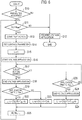
- Fig. 6 is a flow diagram for describing the control method according to the embodiment.
- a flow illustrated in Fig. 6 is started by a connection of the atomizing unit 111 to the electrical unit 112, for example.
- step S10 the controller 51 determines whether or not various types of parameters have been acquired from the memory 111M.
- the various types of parameters include: specific parameters (a, b, T MIN , T MAX ) of the atomizing unit 111; the resistance value (R) of the resistance heating element 111R; and the remaining amount information indicating the remaining amount (M i ) of the aerosol source. If the determination result is YES, the controller 51 performs a process of step S11. If the determination result is NO, the controller 51 performs a process of step S12.
- step S11 the controller 51 determines whether or not the remaining amount (Mi) of the aerosol source is larger than a minimum remaining amount (M MIN ).
- the minimum remaining amount (M MIN ) is a threshold value for determining whether or not the aerosol source consumed during one puff action remains. If the determination result is YES, the controller 51 performs a process of step S13. If the determination result is NO, the controller 51 performs the process of step S12.
- step S12 the controller 51 prohibits the power supply to the resistance heating element 111R.
- the controller 51 may notify a user that the remaining amount of the aerosol source falls below the threshold value, or may notify the user that the remaining amount information cannot be acquired.
- step S13 the controller 51 detects a start of a puff action.
- the start of the puff action can be detected by using an inhalation sensor, for example.
- step S14 the controller 51 sets a control parameter for controlling the power amount supplied to the resistance heating element 111R. Specifically, the controller 51 sets a correction term D for correcting the power amount supplied to the resistance heating element 111R. As described above, D may be used for the correction of the voltage to be applied to the resistance heating element 111R, or may be used for the correction of the duty ratio (that is, the pulse width and the pulse interval). In step S14, the controller 51 may set the voltage corrected based on D, or may set the duty ratio corrected based on D. Further, the controller 51 may set the voltage and duty ratio corrected based on D. D is preferably V C 2 /V A 2 .
- step S14 may be performed before starting voltage application (step S16) to the resistance heating element 111R. Further, the output voltage value VA of the battery may be acquired at the same timing as step S14, or before step S14. The output voltage value VA of the battery is preferably acquired after step S13.
- step S15 the controller 51 increments a counter (i) of the number of puffs.
- step S16 the controller 51 starts the voltage application to the resistance heating element 111R.
- step S17 the controller 51 determines whether or not the puff action has ended.
- the end of the puff action can be detected by using the inhalation sensor, for example. If the determination result is YES, the controller 51 performs a process of step S18. If the determination result is NO, the controller 51 performs a process of step S20.
- step S18 the controller 51 ends the voltage application to the resistance heating element 111R.
- step S19 the controller 51 determines whether or not a time Ti during which the voltage is applied to the resistance heating element 111R is T MIN or below. If the determination result is YES, the controller 51 performs a process of step S22. If the determination result is NO, the controller 51 performs a process of step S23.
- step S20 the controller 51 determines whether or not the time Ti during which the voltage is applied to the resistance heating element 111R is T MAX or above. If the determination result is YES, the controller 51 performs a process of step S21. If the determination result is NO, the controller 51 returns to the process of step S17.
- step S21 the controller 51 ends the voltage application to the resistance heating element 111R.
- D is preferably V C 2 /V A 2 .
- D is preferably V C 2 /V A 2 .
- D is preferably V C 2 /V A 2 .
- E denotes the power amount supplied to the resistance heating element 111R during one puff action
- a and b denote specific parameters of the atomizing unit 111
- L denotes the amount of the aerosol source consumed during one puff action.
- the information stored in the memory 111M includes: specific parameters (a, b, T MIN , T MAX ) of the atomizing unit 111; the resistance value (R) of the resistance heating element 111R; and the remaining amount information indicating the remaining amount (M i ) of the aerosol source.
- the information stored in the memory 111M is identification information associated with the above-described information.
- FIG. 7 is a diagram illustrating the block configuration of the flavor inhaler 100 according to the first modification. It should be noted that in Fig. 7 , same reference numerals are applied to the same configurations as that in Fig. 3 .
- a communication terminal 200 is a terminal having a function of communicating with a server 300.
- the communication terminal 200 includes, for example, a personal computer, a smartphone, and a tablet.
- the server 300 is an example of an external storage medium configured to store specific parameters (a, b, T MIN , T MAX ) of the atomizing unit 111, the resistance value (R) of the resistance heating element 111R, and the remaining amount information indicating the remaining amount (M i ) of the aerosol source. Further, as described above, the memory 111M stores the identification information associated with the above-described information.
- the control circuit 50 includes an external access unit 52.
- the external access unit 52 has a function of directly or indirectly accessing the server 300.
- Fig. 7 illustrates, as an example, a function of the external access unit 52 accessing the server 300 via the communication terminal 200.
- the external access unit 52 may be a module (for example, a USB port) for establishing a wired connection with the communication terminal 200, or may be a module (for example, a Bluetooth module or an NFC (Near Field Communication) module) for establishing a wireless connection with the communication terminal 200, for example.
- the external access unit 52 may have a function of directly communicating with the server 300.
- the external access unit 52 may be a wireless LAN module.
- the external access unit 52 reads out the identification information from the memory 111M, and uses the read-out identification information to acquire information (that is, specific parameters (a, b, T MIN , T MAX ) of the atomizing unit 111, the resistance value (R) of the resistance heating element 111R, and the remaining amount information indicating the remaining amount (Mi) of the aerosol source) associated with the identification information, from the server 300.
- information that is, specific parameters (a, b, T MIN , T MAX ) of the atomizing unit 111, the resistance value (R) of the resistance heating element 111R, and the remaining amount information indicating the remaining amount (Mi) of the aerosol source
- the controller 51 controls the power supplied to the resistance heating element 111R and estimates the remaining amount of the aerosol source, based on the information (that is, specific parameters (a, b, T MIN , T MAX ) of the atomizing unit 111, the resistance value (R) of the resistance heating element 111R, and the remaining amount information indicating the remaining amount (M i ) of the aerosol source) which the external access unit 52 acquires from the server 300 by using the identification information.
- the information that is, specific parameters (a, b, T MIN , T MAX ) of the atomizing unit 111, the resistance value (R) of the resistance heating element 111R, and the remaining amount information indicating the remaining amount (M i ) of the aerosol source
- the information source including the identification information associated with various types of parameters is the memory 111M provided in the atomizing unit 111.
- the information source is a medium or the like provided separately from the atomizing unit 111.
- the medium is, for example, a paper medium indicating the identification information (such as a label attached to an outer surface of the atomizing unit 111, an instruction manual packaged together with the atomizing unit 111, and a container such as a box to house the atomizing unit 111).
- an atomizing unit package 400 has the atomizing unit 111 and a label 111Y attached to an outer surface of the atomizing unit 111.
- the label 111Y is an example of an information source having, as specific information, the identification information associated with various types of parameters.
- Fig. 9 is a diagram illustrating the block configuration of the flavor inhaler 100 according to the second modification. It should be noted that in Fig. 9 , same reference numerals are applied to the same configurations as that in Fig. 7 .
- the communication terminal 200 acquires identification information provided in the label 111Y by inputting the identification information or reading the identification information.
- the communication terminal 200 acquires information (that is, specific parameters (a, b, T MIN , T MAX ) of the atomizing unit 111, the resistance value (R) of the resistance heating element 111R, and the remaining amount information indicating the remaining amount (M i ) of the aerosol source) associated with the acquired identification information, from the server 300.
- the external access unit 52 acquires, from the communication terminal 200, information (that is, specific parameters (a, b, T MIN , T MAX ) of the atomizing unit 111, the resistance value (R) of the resistance heating element 111R, and the remaining amount information indicating the remaining amount (Mi) of the aerosol source) which the communication terminal 200 acquires from the server 300.
- information that is, specific parameters (a, b, T MIN , T MAX ) of the atomizing unit 111, the resistance value (R) of the resistance heating element 111R, and the remaining amount information indicating the remaining amount (Mi) of the aerosol source
- the controller 51 controls the power supplied to the resistance heating element 111R and estimates the remaining amount of the aerosol source, based on the information (that is, specific parameters (a, b, T MIN , T MAX ) of the atomizing unit 111, the resistance value (R) of the resistance heating element 111R, and the remaining amount information indicating the remaining amount (M i ) of the aerosol source) which the external access unit 52 acquires from the server 300 by using the identification information.
- the information that is, specific parameters (a, b, T MIN , T MAX ) of the atomizing unit 111, the resistance value (R) of the resistance heating element 111R, and the remaining amount information indicating the remaining amount (M i ) of the aerosol source
- the second modification describes a case where the communication terminal 200 acquires the identification information from the label 111Y.
- the embodiment is not limited thereto. If the control circuit 50 has a function of inputting the identification information or reading the identification information, the control circuit 50 may acquire the identification information from the label 111Y.
- a medium provided separately from the atomizing unit 111 is used for the information source including the identification information associated with various types of parameters. Therefore, even if the memory 111M is not mounted on the atomizing unit 111, a similar effect to that of the embodiment can be obtained.
- the third modification is based on similar knowledge to that of the embodiment where, as illustrated in Fig. 4 , similarly to the embodiment, E and L at least partly have a linear relationship and such a linear relationship differs for each atomizing unit.
- T is a parameter affected by the length of the puff action, and thus, a predetermined value T 0 is used as the above-described T.
- the predetermined value T 0 is predetermined by assuming the standard length of puff action though it is not limited especially.
- the predetermined value T 0 may be, for example, from 1 second to 4 seconds, and preferably be from 1.5 seconds to 3 seconds.
- the standard length of puff action can be derived from statistics of the length of puff actions of users, and is any value between a lower limit value of the lengths of puff actions by a plurality of users and an upper limit value of the lengths of puff actions by the plurality of users.
- the lower limit value and the upper limit value may be derived as the upper limit value and the lower limit value of a 95% confidence interval of an average value and may be derived as m ⁇ n ⁇ (here, m is an average value, ⁇ is a standard deviation, and n is a positive real number), based on distribution of data of the lengths of puff actions of the users.
- the upper limit value of the standard length of puff action can be derived as m + n ⁇ , as described above, and is about three to four seconds.
- T is controlled by the duty ratio, for example.
- the amount L of the aerosol source consumed during one puff action is designated.
- a method of designating L may be, but not limited to, the following methods.
- the flavor inhaler 100 may include a user interface for designating L, and L may be designated by using the user interface.
- the user interface may be a dial, and L may be designated by an operation (rotation) of the dial.
- the user interface may be a button, and L may be designated by an operation (depression) of the button.
- the user interface may be a touch panel, and L may be designated by an operation (touch) of the touch panel.
- the flavor inhaler 100 may have a communication function, and L may be designated by an external device by using the communication function.
- the external device may be a smartphone, a tablet terminal, and a personal computer.
- the flavor inhaler 100 may include a member (a display or an LED) configured to display information representing the designated L.
- the information representing the designated L may be represented by an absolute value (XX mg) of the amount of aerosol of K-time puff actions generated when an M-second puff action is performed K times at an interval of N seconds, may be represented by an absolute value (XX mg) of the amount of aerosol in one puff action generated when an M-second puff action is performed once, or may be represented by a relative value (a level such as large, medium, and small) of the amount of the aerosol.
- the above-described predetermined value T 0 can be used for the above-described M seconds.
- a method of controlling E by using D may include correcting the voltage to be applied to the resistance heating element 111R (for example, D x V A ) or correcting the duty ratio (that is, the pulse width and the pulse interval) (for example, D x T).
- the correcting the voltage to be applied to the resistance heating element 111R is achieved by using the DC/DC converter.
- the DC/DC converter may be a step-down converter or a step-up converter.
- the controller 51 may control the power amount (E) supplied to the resistance heating element 111R so that E expressed by (L - b)/a does not exceed E MAX .
- E MIN and E MAX may be specified by the voltage Vs, T MIN , and T MAX .
- step S14 illustrated in Fig. 6 can be considered, for example.
- the process of step S14 may be performed before starting the voltage application (step S16) to the resistance heating element 111R.
- the output voltage value V A of the battery may be acquired at the same timing as step S14, or before step S14.
- the output voltage value V A of the battery is preferably acquired after step S13.
- L may be designated in advance. L may be designated for each atomizing unit 111. L may be optionally designated by a user. The method of designating L may be the method using the user interface or may be the method using the communication function, as described above. A timing of designating L should be a timing at which the puff action is not performed (that is, a timing before the puff action is started). The timing of designating L may be between puff actions. The timing of designating L may be before the start of an initial puff action after the atomizing unit 111 is connected to the electrical unit 112. Alternatively, the timing of designating L may be before the start of an initial puff action after the flavor inhaler 100 is powered on.
- the timing of designating L may be before the start of a next puff action when a puff action is not performed over a certain period of time after the puff action ends.
- a timing of acquiring the designated L is not especially limited, but the designated L may be acquired in step S10 or acquired in step S14.
- L is the amount of the aerosol source consumed during one puff action; however, the third modification is not limited thereto.
- Q and L can be considered to have a relation of a proportional function, and thus, Q can be estimated based on L.
- the relation between L and Q can be expressed based on the concentration of the flavor source included in the aerosol source, and thus, Q can be estimated based on L.
- a function representing the relation between L and Q may be specified by actually measuring the concentration of the inhaling flavor component included in the aerosol. Such a specification is performed in the manufacturing stage of the atomizing unit 111, for example.
- a case can be considered where a value of L consumed during an actual puff action differs from a designated value of L.
- a case can be considered where the length of the actual puff action is shorter than the length of the puff action to be referenced when determining the predetermined value T 0 . That is, as for the above-described L, it can be considered that there exist two types of Ls: a designated L A and an actual L B .
- E denotes the power amount supplied to the resistance heating element 111R during one puff action
- a and b denote specific parameters of the atomizing unit 111
- L denotes the amount of the aerosol source consumed during one puff action.
- the user can intuitively easily grasp the amount of aerosol (the amount of the inhaling flavor component) generated by the atomizing unit 111 during one puff action, as a result of controlling E by designating L rather than controlling E by directly designating E.
- the cartridge 130 does not include the atomizing unit 111; however, the embodiment is not limited thereto.
- the cartridge 130 and the atomizing unit 111 may be configured as one unit.
- the atomizing unit 111 may be configured to be connectable to the inhaler main unit 110.
- the memory 111M stores various types of parameters (the specific parameters (a, b, T MIN , T MAX ) of the atomizing unit 111, the resistance value (R) of the resistance heating element 111R, and the remaining amount information indicating the remaining amount (M i ) of the aerosol source).
- the embodiment is not limited thereto.
- the memory 111M may store only a part of various types of parameters and may store identification information associated with the remaining parameters.
- the remaining parameters may be acquired by a similar method to that in the first and second modifications.
- the flow illustrated in Fig. 6 is started by a connection of the atomizing unit 111 to the electrical unit 112.
- the flow illustrated in Fig. 6 may be started by an access to the communication terminal 200 or the server 300 (see the first modification).
- the start and the end of a puff action are detected by using the inhalation sensor.
- the power supply to the resistance heating element 111R may be performed by an operation of a push button, and in such a case, the start and the end of the puff action are detected based on whether the pushbutton is operated.
- the controller 51 may prohibit the power supply to the resistance heating element 111R or may notify the user that the remaining amount information cannot be acquired.
- the above-described embodiments are useful even in a case where the temperature coefficient ⁇ of the resistance value of the resistance heating element is a large value (for example, a value larger than 0.8).
- the resistance value of the resistance heating element 111R at the use temperature should be obtained by applying the temperature coefficient ⁇ to the resistance value of the resistance heating element 111R measured in manufacturing the flavor inhaler 100, and the resistance value of the resistance heating element 111R at the use temperature should be stored in the memory 111M.
- the resistance value of the resistance heating element 111R associated with the identification information stored in the memory 111M should be the resistance value of the resistance heating element 111R at the use temperature.
- the flavor inhaler 100 of a type which heats a liquid aerosol source is described as an example.
- the embodiment is not limited thereto.
- the embodiment may be applied to a flavor inhaler of a type which heats an aerosol source with which a holding member(smoking article) constituted of tobacco materials is impregnated (for example, an article described in US Patent Application Publication No. 2014/0348495 A1 or European Patent No. 2814341 ).
- the state of the aerosol source held in the holding member is not limited to a liquid state, but may be a gel or solid state. That is, the flavor inhaler 100 may have a configuration for heating the aerosol source, and the aerosol source in any state is available.
- a non-burning type flavor inhaler and an atomizing unit which is possible to estimate an amount of an aerosol source consumed during a puff action while an increase in cost and size of the non-burning type flavor inhaler being suppressed.
Landscapes
- Chemical & Material Sciences (AREA)
- Chemical Kinetics & Catalysis (AREA)
- General Chemical & Material Sciences (AREA)
- Engineering & Computer Science (AREA)
- Computer Networks & Wireless Communication (AREA)
- Control Of Resistance Heating (AREA)
- Disinfection, Sterilisation Or Deodorisation Of Air (AREA)
- Nozzles (AREA)
Applications Claiming Priority (2)
| Application Number | Priority Date | Filing Date | Title |
|---|---|---|---|
| PCT/JP2015/077887 WO2017056282A1 (ja) | 2015-09-30 | 2015-09-30 | 非燃焼型香味吸引器及び霧化ユニット |
| PCT/JP2016/078295 WO2017057286A1 (ja) | 2015-09-30 | 2016-09-26 | 非燃焼型香味吸引器及び霧化ユニット |
Publications (3)
| Publication Number | Publication Date |
|---|---|
| EP3348154A1 true EP3348154A1 (de) | 2018-07-18 |
| EP3348154A4 EP3348154A4 (de) | 2019-09-25 |
| EP3348154B1 EP3348154B1 (de) | 2021-03-31 |
Family
ID=58422837
Family Applications (1)
| Application Number | Title | Priority Date | Filing Date |
|---|---|---|---|
| EP16851457.8A Active EP3348154B1 (de) | 2015-09-30 | 2016-09-26 | Verbrennungsfreie aromainhalations- und zerstäubungseinheit |
Country Status (10)
| Country | Link |
|---|---|
| US (1) | US10863773B2 (de) |
| EP (1) | EP3348154B1 (de) |
| JP (1) | JP6450854B2 (de) |
| KR (1) | KR102022814B1 (de) |
| CN (1) | CN108135271B (de) |
| CA (1) | CA3000319C (de) |
| EA (1) | EA037493B1 (de) |
| HK (1) | HK1251978A1 (de) |
| TW (1) | TWI618495B (de) |
| WO (2) | WO2017056282A1 (de) |
Cited By (9)
| Publication number | Priority date | Publication date | Assignee | Title |
|---|---|---|---|---|
| EP3829362A1 (de) * | 2018-07-30 | 2021-06-09 | Philip Morris Products S.A. | E-vaping-vorrichtung |
| EP3820314A4 (de) * | 2019-05-16 | 2021-12-01 | KT&G Corporation | Aerosolerzeugungsvorrichtung und betriebsverfahren dafür |
| US11789476B2 (en) | 2021-01-18 | 2023-10-17 | Altria Client Services Llc | Heat-not-burn (HNB) aerosol-generating devices including intra-draw heater control, and methods of controlling a heater |
| US12232224B2 (en) | 2017-10-11 | 2025-02-18 | Altria Client Services Llc | Folded heater for electronic vaping device |
| EP4175501B1 (de) | 2020-07-15 | 2025-03-19 | Altria Client Services LLC | Elektronischer verdampfer für nikotinfreie fllüssigkeiten mit füllmengeermittlung und automatischer abschaltung |
| US12342846B2 (en) | 2017-10-11 | 2025-07-01 | Altria Client Services Llc | Electronic vaping device including transfer pad with oriented fibers |
| US12357023B2 (en) | 2017-10-11 | 2025-07-15 | Altria Client Services Llc | Electronic vaping device including transfer pad with oriented fibers |
| US12432817B2 (en) | 2017-12-29 | 2025-09-30 | Altria Client Services Llc | Electronic vaping device with outlet-end illumination |
| US12520880B2 (en) | 2021-01-18 | 2026-01-13 | Altria Client Services Llc | Heat-not-burn (HNB) aerosol-generating devices including energy based heater control, and methods of controlling a heater |
Families Citing this family (53)
| Publication number | Priority date | Publication date | Assignee | Title |
|---|---|---|---|---|
| US10244793B2 (en) | 2005-07-19 | 2019-04-02 | Juul Labs, Inc. | Devices for vaporization of a substance |
| US10279934B2 (en) | 2013-03-15 | 2019-05-07 | Juul Labs, Inc. | Fillable vaporizer cartridge and method of filling |
| US10058129B2 (en) | 2013-12-23 | 2018-08-28 | Juul Labs, Inc. | Vaporization device systems and methods |
| US10159282B2 (en) | 2013-12-23 | 2018-12-25 | Juul Labs, Inc. | Cartridge for use with a vaporizer device |
| KR102267997B1 (ko) | 2013-12-23 | 2021-06-23 | 쥴 랩스, 인크. | 기화 디바이스 시스템 및 방법 |
| US10076139B2 (en) | 2013-12-23 | 2018-09-18 | Juul Labs, Inc. | Vaporizer apparatus |
| US20160366947A1 (en) | 2013-12-23 | 2016-12-22 | James Monsees | Vaporizer apparatus |
| USD825102S1 (en) | 2016-07-28 | 2018-08-07 | Juul Labs, Inc. | Vaporizer device with cartridge |
| USD842536S1 (en) | 2016-07-28 | 2019-03-05 | Juul Labs, Inc. | Vaporizer cartridge |
| KR102627987B1 (ko) | 2014-12-05 | 2024-01-22 | 쥴 랩스, 인크. | 교정된 투여량 제어 |
| MX377347B (es) | 2016-02-11 | 2025-03-07 | Juul Labs Inc | Cartucho rellenable de vaporizador y metodo de relleno |
| WO2017139675A1 (en) | 2016-02-11 | 2017-08-17 | Pax Labs, Inc. | Securely attaching cartridges for vaporizer devices |
| US10405582B2 (en) | 2016-03-10 | 2019-09-10 | Pax Labs, Inc. | Vaporization device with lip sensing |
| USD849996S1 (en) | 2016-06-16 | 2019-05-28 | Pax Labs, Inc. | Vaporizer cartridge |
| USD851830S1 (en) | 2016-06-23 | 2019-06-18 | Pax Labs, Inc. | Combined vaporizer tamp and pick tool |
| USD836541S1 (en) | 2016-06-23 | 2018-12-25 | Pax Labs, Inc. | Charging device |
| EP3984393A1 (de) * | 2017-04-11 | 2022-04-20 | KT&G Corporation | Aerosolerzeugungsvorrichtung und verfahren zur bereitstellung adaptiver rückkopplung durch pufferkennung |
| JP6942814B2 (ja) * | 2017-04-11 | 2021-09-29 | ケーティー・アンド・ジー・コーポレーション | ヒータを事前予熱するエアロゾル生成システム |
| JP7203040B2 (ja) * | 2017-05-03 | 2023-01-12 | フィリップ・モーリス・プロダクツ・ソシエテ・アノニム | 電気加熱式エアロゾル発生装置における温度制御のためのシステムおよび方法 |
| KR20180124739A (ko) * | 2017-05-11 | 2018-11-21 | 주식회사 케이티앤지 | 궐련의 종류별로 에어로졸 생성장치에 포함된 히터의 온도를 제어하는 방법 및 궐련의 종류별로 히터의 온도를 제어하는 에어로졸 생성장치 |
| WO2019049194A1 (ja) * | 2017-09-05 | 2019-03-14 | 秀輝 角島 | 二段階フレーバー式電子タバコ |
| USD887632S1 (en) | 2017-09-14 | 2020-06-16 | Pax Labs, Inc. | Vaporizer cartridge |
| GB201721646D0 (en) | 2017-12-21 | 2018-02-07 | British American Tobacco Investments Ltd | Aerosol provision device |
| TW201929702A (zh) * | 2017-12-29 | 2019-08-01 | 瑞士商傑太日煙國際股份有限公司 | 用於一蒸氣產生裝置之加熱總成 |
| CN119097122A (zh) | 2018-02-27 | 2024-12-10 | 尤尔实验室有限公司 | 质量输出受控的蒸发器 |
| WO2019186670A1 (ja) * | 2018-03-26 | 2019-10-03 | 日本たばこ産業株式会社 | エアロゾル生成装置及び制御方法並びにプログラム |
| GB201805168D0 (en) * | 2018-03-29 | 2018-05-16 | Nicoventures Holdings Ltd | A control device for an electronic aerosol provision system |
| GB201807497D0 (en) * | 2018-05-08 | 2018-06-20 | Nicoventures Trading Ltd | An aerosol provision device |
| US11039504B2 (en) * | 2018-10-01 | 2021-06-15 | Semiconductor Components Industries, Llc | Methods and apparatus for a power supply control circuit |
| JP6577113B1 (ja) * | 2018-10-03 | 2019-09-18 | 日本たばこ産業株式会社 | エアロゾル生成装置、エアロゾル生成装置用の制御ユニット、方法及びプログラム |
| EP3664630B1 (de) | 2018-10-15 | 2022-02-16 | Juul Labs, Inc. | Heizelement |
| US12256784B2 (en) | 2018-10-17 | 2025-03-25 | Juul Labs, Inc. | Cartridge for a vaporizer device |
| WO2020092245A1 (en) * | 2018-10-29 | 2020-05-07 | Zorday IP, LLC | Network-enabled electronic cigarette |
| EP3876765B1 (de) | 2018-11-05 | 2024-08-14 | Juul Labs, Inc. | Kartuschen für verdampfervorrichtungen |
| JP7158557B2 (ja) * | 2019-02-27 | 2022-10-21 | 日本たばこ産業株式会社 | 香味成分生成制御装置、香味成分生成装置、制御方法及びプログラム |
| WO2020194518A1 (ja) * | 2019-03-26 | 2020-10-01 | 日本たばこ産業株式会社 | 情報処理装置、情報処理方法、及びプログラム |
| KR102278590B1 (ko) * | 2019-04-18 | 2021-07-16 | 주식회사 케이티앤지 | 에어로졸 생성 장치 및 그의 동작 방법 |
| JP7253052B2 (ja) * | 2019-07-03 | 2023-04-05 | 日本たばこ産業株式会社 | 吸引装置の電源ユニットを動作させる方法、吸引装置の電源ユニット、及びコンピュータ可読媒体 |
| TWI858000B (zh) * | 2020-01-06 | 2024-10-11 | 南韓商Lg新能源股份有限公司 | 電子菸裝置 |
| JP6841950B1 (ja) * | 2020-03-05 | 2021-03-10 | 日本たばこ産業株式会社 | 吸引器用コントローラ |
| KR102430544B1 (ko) * | 2020-04-08 | 2022-08-08 | 주식회사 케이티앤지 | 에어로졸 생성 장치 및 이를 제어하는 방법 |
| EP4721607A2 (de) | 2020-04-15 | 2026-04-08 | Juul Labs, Inc. | Kartusche für verdampfervorrichtung |
| GB202006778D0 (en) * | 2020-05-07 | 2020-06-24 | Nicoventures Trading Ltd | Non-combustible aerosol provision system |
| KR102524632B1 (ko) * | 2020-07-07 | 2023-04-21 | 주식회사 케이티앤지 | 에어로졸 생성 장치 |
| JP7610361B2 (ja) * | 2020-07-08 | 2025-01-08 | 日本たばこ産業株式会社 | エアロゾル生成装置の制御ユニット |
| JP6833093B1 (ja) * | 2020-07-09 | 2021-02-24 | 日本たばこ産業株式会社 | エアロゾル生成装置の電源ユニット、及びエアロゾル生成装置 |
| JP7761597B2 (ja) * | 2020-07-15 | 2025-10-28 | ジェイティー インターナショナル エスエイ | エアロゾル発生装置を管理する方法 |
| US12102132B2 (en) * | 2020-07-15 | 2024-10-01 | Altria Client Services Llc | Nicotine electronic vaping devices having nicotine pre-vapor formulation level detection and auto shutdown |
| IL300944A (en) * | 2020-09-04 | 2023-04-01 | Philip Morris Products Sa | A smoking device with a heating profile based on puff volume |
| CN113383998B (zh) * | 2020-09-29 | 2024-03-22 | 重庆中烟工业有限责任公司 | 一种用于调控双烟弹加热不燃烧烟气溶胶烟雾的方法和装置 |
| CN112931980A (zh) * | 2021-01-27 | 2021-06-11 | 深圳麦克韦尔科技有限公司 | 一种用于控制雾化器工作的装置以及雾化工作方法 |
| US12550942B2 (en) | 2022-09-19 | 2026-02-17 | Altria Client Services Llc | Session control system |
| US20260068951A1 (en) * | 2024-09-12 | 2026-03-12 | Kt&G Corporation | Aerosol generating apparatus and method of controlling aerosol generating apparatus |
Family Cites Families (25)
| Publication number | Priority date | Publication date | Assignee | Title |
|---|---|---|---|---|
| US4947875A (en) * | 1988-09-08 | 1990-08-14 | R. J. Reynolds Tobacco Company | Flavor delivery articles utilizing electrical energy |
| US4947874A (en) * | 1988-09-08 | 1990-08-14 | R. J. Reynolds Tobacco Company | Smoking articles utilizing electrical energy |
| US4922901A (en) * | 1988-09-08 | 1990-05-08 | R. J. Reynolds Tobacco Company | Drug delivery articles utilizing electrical energy |
| US5505214A (en) * | 1991-03-11 | 1996-04-09 | Philip Morris Incorporated | Electrical smoking article and method for making same |
| US5666977A (en) * | 1993-06-10 | 1997-09-16 | Philip Morris Incorporated | Electrical smoking article using liquid tobacco flavor medium delivery system |
| TWM275721U (en) * | 2005-04-08 | 2005-09-21 | Lik Hon | Electronic smoke atomization |
| WO2008015918A1 (fr) * | 2006-08-01 | 2008-02-07 | Japan Tobacco Inc. | Dispositif d'aspiration d'aérosol et son procédé d'aspiration |
| EP2113178A1 (de) * | 2008-04-30 | 2009-11-04 | Philip Morris Products S.A. | Elektrisch beheiztes Rauchsystem mit einem Element zur Flüssigkeitsspeicherung |
| JP2011128792A (ja) | 2009-12-16 | 2011-06-30 | Toshiba Corp | メモリ管理装置 |
| PL2563172T5 (pl) * | 2010-04-30 | 2022-08-29 | Fontem Holdings 4 B.V. | Urządzenie elektroniczne do palenia |
| LT2982255T (lt) * | 2010-08-24 | 2019-08-12 | Jt International Sa | Inhaliacinis įtaisas su medžiagos naudojimo reguliavimu |
| EP2460423A1 (de) * | 2010-12-03 | 2012-06-06 | Philip Morris Products S.A. | Elektrisch beheiztes Aerosolerzeugungssystem mit verbesserter Heizungssteuerung |
| EP2468116A1 (de) * | 2010-12-24 | 2012-06-27 | Philip Morris Products S.A. | Aerosolerzeugungssystem mit Mitteln zur Steuerung des Verbrauchs eines Flüssigsubstrats |
| EP2468117A1 (de) | 2010-12-24 | 2012-06-27 | Philip Morris Products S.A. | Aerosolerzeugungssystem mit Mitteln zur Bestimmung der Erschöpfung eines Flüssigsubstrats |
| HUE040751T2 (hu) * | 2011-10-27 | 2019-03-28 | Philip Morris Products Sa | Aeroszol-fejlesztõ rendszer továbbfejlesztett aeroszol-elõállítással |
| MY177353A (en) * | 2011-12-30 | 2020-09-14 | Philip Morris Products Sa | Aerosol-generating system with consumption monitoring and feedback |
| CN104114049A (zh) * | 2012-03-26 | 2014-10-22 | 韩国极光科技有限公司 | 雾化控制单元及包括该雾化控制单元的便携式雾化装置 |
| US8910640B2 (en) * | 2013-01-30 | 2014-12-16 | R.J. Reynolds Tobacco Company | Wick suitable for use in an electronic smoking article |
| JP2015049046A (ja) | 2013-08-29 | 2015-03-16 | アルプス電気株式会社 | 角度検出装置 |
| MY175490A (en) * | 2013-09-30 | 2020-06-30 | Japan Tobacco Inc | Non-burning type flavor inhaler |
| EP2856893B2 (de) | 2013-10-02 | 2023-10-04 | Fontem Holdings 1 B.V. | Elektronische Rauchvorrichtung |
| CN103653261B (zh) * | 2013-12-13 | 2016-03-23 | 上海烟草集团有限责任公司 | 一种智能电子烟 |
| CN103734915B (zh) * | 2014-01-13 | 2016-09-14 | 惠州市吉瑞科技有限公司 | 一种限定使用寿命的电子烟及限定电子烟使用寿命的方法 |
| WO2015107552A1 (en) * | 2014-01-17 | 2015-07-23 | Godfrey Phillips India Limited | Device and method of vaporizing a liquid material |
| GB201410171D0 (en) * | 2014-06-09 | 2014-07-23 | Nicoventures Holdings Ltd | Electronic vapour provision system |
-
2015
- 2015-09-30 WO PCT/JP2015/077887 patent/WO2017056282A1/ja not_active Ceased
-
2016
- 2016-09-26 EP EP16851457.8A patent/EP3348154B1/de active Active
- 2016-09-26 JP JP2017543266A patent/JP6450854B2/ja not_active Expired - Fee Related
- 2016-09-26 WO PCT/JP2016/078295 patent/WO2017057286A1/ja not_active Ceased
- 2016-09-26 HK HK18111298.6A patent/HK1251978A1/zh unknown
- 2016-09-26 CN CN201680057079.9A patent/CN108135271B/zh not_active Expired - Fee Related
- 2016-09-26 CA CA3000319A patent/CA3000319C/en active Active
- 2016-09-26 EA EA201890837A patent/EA037493B1/ru not_active IP Right Cessation
- 2016-09-26 KR KR1020187008841A patent/KR102022814B1/ko not_active Expired - Fee Related
- 2016-09-30 TW TW105131578A patent/TWI618495B/zh not_active IP Right Cessation
-
2018
- 2018-03-30 US US15/941,417 patent/US10863773B2/en not_active Expired - Fee Related
Cited By (16)
| Publication number | Priority date | Publication date | Assignee | Title |
|---|---|---|---|---|
| US12232224B2 (en) | 2017-10-11 | 2025-02-18 | Altria Client Services Llc | Folded heater for electronic vaping device |
| US12396482B2 (en) | 2017-10-11 | 2025-08-26 | Altria Client Services Llc | Electronic vaping device including transfer pad with oriented fibers |
| US12369618B2 (en) | 2017-10-11 | 2025-07-29 | Altria Client Services Llc | Electronic vaping device including transfer pad with oriented fibers |
| US12357023B2 (en) | 2017-10-11 | 2025-07-15 | Altria Client Services Llc | Electronic vaping device including transfer pad with oriented fibers |
| US12342846B2 (en) | 2017-10-11 | 2025-07-01 | Altria Client Services Llc | Electronic vaping device including transfer pad with oriented fibers |
| US12432817B2 (en) | 2017-12-29 | 2025-09-30 | Altria Client Services Llc | Electronic vaping device with outlet-end illumination |
| US12439478B2 (en) | 2017-12-29 | 2025-10-07 | Altria Client Services Llc | Electronic vaping device with outlet-end illumination |
| EP4445785A3 (de) * | 2018-07-30 | 2025-01-08 | Philip Morris Products S.A. | Elektronische vaping-vorrichtung |
| EP3829362A1 (de) * | 2018-07-30 | 2021-06-09 | Philip Morris Products S.A. | E-vaping-vorrichtung |
| US12476316B2 (en) | 2018-07-30 | 2025-11-18 | Altria Client Services Llc | Electronic vaping device |
| US11957179B2 (en) | 2019-05-16 | 2024-04-16 | Kt&G Corporation | Aerosol generating device and operation method thereof |
| EP4108112A1 (de) * | 2019-05-16 | 2022-12-28 | KT&G Corporation | Aerosolerzeugungsvorrichtung und betriebsverfahren dafür |
| EP3820314A4 (de) * | 2019-05-16 | 2021-12-01 | KT&G Corporation | Aerosolerzeugungsvorrichtung und betriebsverfahren dafür |
| EP4175501B1 (de) | 2020-07-15 | 2025-03-19 | Altria Client Services LLC | Elektronischer verdampfer für nikotinfreie fllüssigkeiten mit füllmengeermittlung und automatischer abschaltung |
| US11789476B2 (en) | 2021-01-18 | 2023-10-17 | Altria Client Services Llc | Heat-not-burn (HNB) aerosol-generating devices including intra-draw heater control, and methods of controlling a heater |
| US12520880B2 (en) | 2021-01-18 | 2026-01-13 | Altria Client Services Llc | Heat-not-burn (HNB) aerosol-generating devices including energy based heater control, and methods of controlling a heater |
Also Published As
| Publication number | Publication date |
|---|---|
| KR102022814B1 (ko) | 2019-09-18 |
| KR20180044409A (ko) | 2018-05-02 |
| EA201890837A1 (ru) | 2018-08-31 |
| JP6450854B2 (ja) | 2019-01-09 |
| EP3348154B1 (de) | 2021-03-31 |
| WO2017056282A1 (ja) | 2017-04-06 |
| US10863773B2 (en) | 2020-12-15 |
| WO2017057286A1 (ja) | 2017-04-06 |
| CA3000319C (en) | 2020-01-07 |
| TW201717789A (zh) | 2017-06-01 |
| HK1251978A1 (zh) | 2019-05-10 |
| EA037493B1 (ru) | 2021-04-02 |
| EP3348154A4 (de) | 2019-09-25 |
| TWI618495B (zh) | 2018-03-21 |
| CN108135271B (zh) | 2020-08-25 |
| CN108135271A (zh) | 2018-06-08 |
| JPWO2017057286A1 (ja) | 2018-03-08 |
| CA3000319A1 (en) | 2017-04-06 |
| US20180220711A1 (en) | 2018-08-09 |
Similar Documents
| Publication | Publication Date | Title |
|---|---|---|
| US10863773B2 (en) | Non-burning type flavor inhaler and atomizing unit calculating the amount of aerosol consumed | |
| KR102183093B1 (ko) | 온도를 가변적으로 제어할 수 있는 방법 및 장치 | |
| US11044945B2 (en) | Flavor inhaler, cartridge, and flavor unit | |
| US10881148B2 (en) | Flavor inhaler | |
| JP7345014B2 (ja) | エアロゾル生成装置及びそれを制御する方法 | |
| EP3260000B1 (de) | Verfahren zur herstellung einer zerstäubungseinheit | |
| KR102253052B1 (ko) | 에어로졸 생성 장치 및 그의 동작 방법 | |
| EP3406147A1 (de) | Verbrennungsfreier aromainhalator, verfahren, programm und speichermedium | |
| CN122003188A (zh) | 气溶胶生成装置 | |
| HK40001106B (zh) | 香味吸入器、烟弹及香味单元 |
Legal Events
| Date | Code | Title | Description |
|---|---|---|---|
| STAA | Information on the status of an ep patent application or granted ep patent |
Free format text: STATUS: THE INTERNATIONAL PUBLICATION HAS BEEN MADE |
|
| PUAI | Public reference made under article 153(3) epc to a published international application that has entered the european phase |
Free format text: ORIGINAL CODE: 0009012 |
|
| STAA | Information on the status of an ep patent application or granted ep patent |
Free format text: STATUS: REQUEST FOR EXAMINATION WAS MADE |
|
| 17P | Request for examination filed |
Effective date: 20180409 |
|
| AK | Designated contracting states |
Kind code of ref document: A1 Designated state(s): AL AT BE BG CH CY CZ DE DK EE ES FI FR GB GR HR HU IE IS IT LI LT LU LV MC MK MT NL NO PL PT RO RS SE SI SK SM TR |
|
| AX | Request for extension of the european patent |
Extension state: BA ME |
|
| DAV | Request for validation of the european patent (deleted) | ||
| DAX | Request for extension of the european patent (deleted) | ||
| A4 | Supplementary search report drawn up and despatched |
Effective date: 20190823 |
|
| RIC1 | Information provided on ipc code assigned before grant |
Ipc: A24F 47/00 20060101AFI20190819BHEP Ipc: H05B 3/44 20060101ALI20190819BHEP |
|
| STAA | Information on the status of an ep patent application or granted ep patent |
Free format text: STATUS: EXAMINATION IS IN PROGRESS |
|
| 17Q | First examination report despatched |
Effective date: 20200424 |
|
| REG | Reference to a national code |
Ref country code: DE Ref legal event code: R079 Ref document number: 602016055400 Country of ref document: DE Free format text: PREVIOUS MAIN CLASS: A24F0047000000 Ipc: A24F0040500000 |
|
| GRAP | Despatch of communication of intention to grant a patent |
Free format text: ORIGINAL CODE: EPIDOSNIGR1 |
|
| STAA | Information on the status of an ep patent application or granted ep patent |
Free format text: STATUS: GRANT OF PATENT IS INTENDED |
|
| RIC1 | Information provided on ipc code assigned before grant |
Ipc: A24F 47/00 20200101ALI20200827BHEP Ipc: A24F 40/65 20200101ALI20200827BHEP Ipc: A24F 40/50 20200101AFI20200827BHEP |
|
| INTG | Intention to grant announced |
Effective date: 20200929 |
|
| GRAS | Grant fee paid |
Free format text: ORIGINAL CODE: EPIDOSNIGR3 |
|
| GRAA | (expected) grant |
Free format text: ORIGINAL CODE: 0009210 |
|
| STAA | Information on the status of an ep patent application or granted ep patent |
Free format text: STATUS: THE PATENT HAS BEEN GRANTED |
|
| AK | Designated contracting states |
Kind code of ref document: B1 Designated state(s): AL AT BE BG CH CY CZ DE DK EE ES FI FR GB GR HR HU IE IS IT LI LT LU LV MC MK MT NL NO PL PT RO RS SE SI SK SM TR |
|
| REG | Reference to a national code |
Ref country code: GB Ref legal event code: FG4D Ref country code: CH Ref legal event code: EP |
|
| REG | Reference to a national code |
Ref country code: AT Ref legal event code: REF Ref document number: 1375932 Country of ref document: AT Kind code of ref document: T Effective date: 20210415 |
|
| REG | Reference to a national code |
Ref country code: DE Ref legal event code: R096 Ref document number: 602016055400 Country of ref document: DE |
|
| REG | Reference to a national code |
Ref country code: IE Ref legal event code: FG4D |
|
| REG | Reference to a national code |
Ref country code: LT Ref legal event code: MG9D |
|
| PG25 | Lapsed in a contracting state [announced via postgrant information from national office to epo] |
Ref country code: BG Free format text: LAPSE BECAUSE OF FAILURE TO SUBMIT A TRANSLATION OF THE DESCRIPTION OR TO PAY THE FEE WITHIN THE PRESCRIBED TIME-LIMIT Effective date: 20210630 Ref country code: FI Free format text: LAPSE BECAUSE OF FAILURE TO SUBMIT A TRANSLATION OF THE DESCRIPTION OR TO PAY THE FEE WITHIN THE PRESCRIBED TIME-LIMIT Effective date: 20210331 Ref country code: HR Free format text: LAPSE BECAUSE OF FAILURE TO SUBMIT A TRANSLATION OF THE DESCRIPTION OR TO PAY THE FEE WITHIN THE PRESCRIBED TIME-LIMIT Effective date: 20210331 Ref country code: NO Free format text: LAPSE BECAUSE OF FAILURE TO SUBMIT A TRANSLATION OF THE DESCRIPTION OR TO PAY THE FEE WITHIN THE PRESCRIBED TIME-LIMIT Effective date: 20210630 |
|
| PG25 | Lapsed in a contracting state [announced via postgrant information from national office to epo] |
Ref country code: SE Free format text: LAPSE BECAUSE OF FAILURE TO SUBMIT A TRANSLATION OF THE DESCRIPTION OR TO PAY THE FEE WITHIN THE PRESCRIBED TIME-LIMIT Effective date: 20210331 Ref country code: LV Free format text: LAPSE BECAUSE OF FAILURE TO SUBMIT A TRANSLATION OF THE DESCRIPTION OR TO PAY THE FEE WITHIN THE PRESCRIBED TIME-LIMIT Effective date: 20210331 Ref country code: RS Free format text: LAPSE BECAUSE OF FAILURE TO SUBMIT A TRANSLATION OF THE DESCRIPTION OR TO PAY THE FEE WITHIN THE PRESCRIBED TIME-LIMIT Effective date: 20210331 |
|
| REG | Reference to a national code |
Ref country code: NL Ref legal event code: MP Effective date: 20210331 |
|
| REG | Reference to a national code |
Ref country code: AT Ref legal event code: MK05 Ref document number: 1375932 Country of ref document: AT Kind code of ref document: T Effective date: 20210331 |
|
| PG25 | Lapsed in a contracting state [announced via postgrant information from national office to epo] |
Ref country code: LT Free format text: LAPSE BECAUSE OF FAILURE TO SUBMIT A TRANSLATION OF THE DESCRIPTION OR TO PAY THE FEE WITHIN THE PRESCRIBED TIME-LIMIT Effective date: 20210331 Ref country code: CZ Free format text: LAPSE BECAUSE OF FAILURE TO SUBMIT A TRANSLATION OF THE DESCRIPTION OR TO PAY THE FEE WITHIN THE PRESCRIBED TIME-LIMIT Effective date: 20210331 Ref country code: EE Free format text: LAPSE BECAUSE OF FAILURE TO SUBMIT A TRANSLATION OF THE DESCRIPTION OR TO PAY THE FEE WITHIN THE PRESCRIBED TIME-LIMIT Effective date: 20210331 Ref country code: AT Free format text: LAPSE BECAUSE OF FAILURE TO SUBMIT A TRANSLATION OF THE DESCRIPTION OR TO PAY THE FEE WITHIN THE PRESCRIBED TIME-LIMIT Effective date: 20210331 Ref country code: NL Free format text: LAPSE BECAUSE OF FAILURE TO SUBMIT A TRANSLATION OF THE DESCRIPTION OR TO PAY THE FEE WITHIN THE PRESCRIBED TIME-LIMIT Effective date: 20210331 Ref country code: SM Free format text: LAPSE BECAUSE OF FAILURE TO SUBMIT A TRANSLATION OF THE DESCRIPTION OR TO PAY THE FEE WITHIN THE PRESCRIBED TIME-LIMIT Effective date: 20210331 |
|
| PG25 | Lapsed in a contracting state [announced via postgrant information from national office to epo] |
Ref country code: PT Free format text: LAPSE BECAUSE OF FAILURE TO SUBMIT A TRANSLATION OF THE DESCRIPTION OR TO PAY THE FEE WITHIN THE PRESCRIBED TIME-LIMIT Effective date: 20210802 Ref country code: PL Free format text: LAPSE BECAUSE OF FAILURE TO SUBMIT A TRANSLATION OF THE DESCRIPTION OR TO PAY THE FEE WITHIN THE PRESCRIBED TIME-LIMIT Effective date: 20210331 Ref country code: RO Free format text: LAPSE BECAUSE OF FAILURE TO SUBMIT A TRANSLATION OF THE DESCRIPTION OR TO PAY THE FEE WITHIN THE PRESCRIBED TIME-LIMIT Effective date: 20210331 Ref country code: SK Free format text: LAPSE BECAUSE OF FAILURE TO SUBMIT A TRANSLATION OF THE DESCRIPTION OR TO PAY THE FEE WITHIN THE PRESCRIBED TIME-LIMIT Effective date: 20210331 Ref country code: IS Free format text: LAPSE BECAUSE OF FAILURE TO SUBMIT A TRANSLATION OF THE DESCRIPTION OR TO PAY THE FEE WITHIN THE PRESCRIBED TIME-LIMIT Effective date: 20210731 |
|
| REG | Reference to a national code |
Ref country code: DE Ref legal event code: R097 Ref document number: 602016055400 Country of ref document: DE |
|
| PG25 | Lapsed in a contracting state [announced via postgrant information from national office to epo] |
Ref country code: AL Free format text: LAPSE BECAUSE OF FAILURE TO SUBMIT A TRANSLATION OF THE DESCRIPTION OR TO PAY THE FEE WITHIN THE PRESCRIBED TIME-LIMIT Effective date: 20210331 Ref country code: DK Free format text: LAPSE BECAUSE OF FAILURE TO SUBMIT A TRANSLATION OF THE DESCRIPTION OR TO PAY THE FEE WITHIN THE PRESCRIBED TIME-LIMIT Effective date: 20210331 Ref country code: ES Free format text: LAPSE BECAUSE OF FAILURE TO SUBMIT A TRANSLATION OF THE DESCRIPTION OR TO PAY THE FEE WITHIN THE PRESCRIBED TIME-LIMIT Effective date: 20210331 |
|
| PLBE | No opposition filed within time limit |
Free format text: ORIGINAL CODE: 0009261 |
|
| STAA | Information on the status of an ep patent application or granted ep patent |
Free format text: STATUS: NO OPPOSITION FILED WITHIN TIME LIMIT |
|
| 26N | No opposition filed |
Effective date: 20220104 |
|
| REG | Reference to a national code |
Ref country code: CH Ref legal event code: PL |
|
| REG | Reference to a national code |
Ref country code: BE Ref legal event code: MM Effective date: 20210930 |
|
| GBPC | Gb: european patent ceased through non-payment of renewal fee |
Effective date: 20210926 |
|
| PG25 | Lapsed in a contracting state [announced via postgrant information from national office to epo] |
Ref country code: IS Free format text: LAPSE BECAUSE OF FAILURE TO SUBMIT A TRANSLATION OF THE DESCRIPTION OR TO PAY THE FEE WITHIN THE PRESCRIBED TIME-LIMIT Effective date: 20210731 Ref country code: MC Free format text: LAPSE BECAUSE OF FAILURE TO SUBMIT A TRANSLATION OF THE DESCRIPTION OR TO PAY THE FEE WITHIN THE PRESCRIBED TIME-LIMIT Effective date: 20210331 |
|
| PG25 | Lapsed in a contracting state [announced via postgrant information from national office to epo] |
Ref country code: LU Free format text: LAPSE BECAUSE OF NON-PAYMENT OF DUE FEES Effective date: 20210926 Ref country code: IT Free format text: LAPSE BECAUSE OF FAILURE TO SUBMIT A TRANSLATION OF THE DESCRIPTION OR TO PAY THE FEE WITHIN THE PRESCRIBED TIME-LIMIT Effective date: 20210331 Ref country code: IE Free format text: LAPSE BECAUSE OF NON-PAYMENT OF DUE FEES Effective date: 20210926 Ref country code: GB Free format text: LAPSE BECAUSE OF NON-PAYMENT OF DUE FEES Effective date: 20210926 Ref country code: FR Free format text: LAPSE BECAUSE OF NON-PAYMENT OF DUE FEES Effective date: 20210930 Ref country code: BE Free format text: LAPSE BECAUSE OF NON-PAYMENT OF DUE FEES Effective date: 20210930 |
|
| PG25 | Lapsed in a contracting state [announced via postgrant information from national office to epo] |
Ref country code: LI Free format text: LAPSE BECAUSE OF NON-PAYMENT OF DUE FEES Effective date: 20210930 Ref country code: CH Free format text: LAPSE BECAUSE OF NON-PAYMENT OF DUE FEES Effective date: 20210930 |
|
| PG25 | Lapsed in a contracting state [announced via postgrant information from national office to epo] |
Ref country code: HU Free format text: LAPSE BECAUSE OF FAILURE TO SUBMIT A TRANSLATION OF THE DESCRIPTION OR TO PAY THE FEE WITHIN THE PRESCRIBED TIME-LIMIT; INVALID AB INITIO Effective date: 20160926 |
|
| PG25 | Lapsed in a contracting state [announced via postgrant information from national office to epo] |
Ref country code: CY Free format text: LAPSE BECAUSE OF FAILURE TO SUBMIT A TRANSLATION OF THE DESCRIPTION OR TO PAY THE FEE WITHIN THE PRESCRIBED TIME-LIMIT Effective date: 20210331 |
|
| P01 | Opt-out of the competence of the unified patent court (upc) registered |
Effective date: 20230530 |
|
| PG25 | Lapsed in a contracting state [announced via postgrant information from national office to epo] |
Ref country code: GR Free format text: LAPSE BECAUSE OF FAILURE TO SUBMIT A TRANSLATION OF THE DESCRIPTION OR TO PAY THE FEE WITHIN THE PRESCRIBED TIME-LIMIT Effective date: 20210331 |
|
| PGFP | Annual fee paid to national office [announced via postgrant information from national office to epo] |
Ref country code: DE Payment date: 20221212 Year of fee payment: 8 |
|
| PG25 | Lapsed in a contracting state [announced via postgrant information from national office to epo] |
Ref country code: MK Free format text: LAPSE BECAUSE OF FAILURE TO SUBMIT A TRANSLATION OF THE DESCRIPTION OR TO PAY THE FEE WITHIN THE PRESCRIBED TIME-LIMIT Effective date: 20210331 |
|
| PG25 | Lapsed in a contracting state [announced via postgrant information from national office to epo] |
Ref country code: MT Free format text: LAPSE BECAUSE OF FAILURE TO SUBMIT A TRANSLATION OF THE DESCRIPTION OR TO PAY THE FEE WITHIN THE PRESCRIBED TIME-LIMIT Effective date: 20210331 |
|
| REG | Reference to a national code |
Ref country code: DE Ref legal event code: R119 Ref document number: 602016055400 Country of ref document: DE |
|
| PG25 | Lapsed in a contracting state [announced via postgrant information from national office to epo] |
Ref country code: DE Free format text: LAPSE BECAUSE OF NON-PAYMENT OF DUE FEES Effective date: 20250401 |
|
| PG25 | Lapsed in a contracting state [announced via postgrant information from national office to epo] |
Ref country code: TR Free format text: LAPSE BECAUSE OF FAILURE TO SUBMIT A TRANSLATION OF THE DESCRIPTION OR TO PAY THE FEE WITHIN THE PRESCRIBED TIME-LIMIT Effective date: 20210331 |