EP3348314B1 - Système de fonctionnement, système de jeu et organe de commande de jeu pouvantidentifier un dispositif connecté ayant un programme simplifié - Google Patents
Système de fonctionnement, système de jeu et organe de commande de jeu pouvantidentifier un dispositif connecté ayant un programme simplifié Download PDFInfo
- Publication number
- EP3348314B1 EP3348314B1 EP17165024.5A EP17165024A EP3348314B1 EP 3348314 B1 EP3348314 B1 EP 3348314B1 EP 17165024 A EP17165024 A EP 17165024A EP 3348314 B1 EP3348314 B1 EP 3348314B1
- Authority
- EP
- European Patent Office
- Prior art keywords
- battery
- terminal
- controller
- game controller
- unit
- Prior art date
- Legal status (The legal status is an assumption and is not a legal conclusion. Google has not performed a legal analysis and makes no representation as to the accuracy of the status listed.)
- Active
Links
Images






Classifications
-
- A—HUMAN NECESSITIES
- A63—SPORTS; GAMES; AMUSEMENTS
- A63F—CARD, BOARD, OR ROULETTE GAMES; INDOOR GAMES USING SMALL MOVING PLAYING BODIES; VIDEO GAMES; GAMES NOT OTHERWISE PROVIDED FOR
- A63F13/00—Video games, i.e. games using an electronically generated display having two or more dimensions
- A63F13/20—Input arrangements for video game devices
- A63F13/24—Constructional details thereof, e.g. game controllers with detachable joystick handles
-
- A—HUMAN NECESSITIES
- A63—SPORTS; GAMES; AMUSEMENTS
- A63F—CARD, BOARD, OR ROULETTE GAMES; INDOOR GAMES USING SMALL MOVING PLAYING BODIES; VIDEO GAMES; GAMES NOT OTHERWISE PROVIDED FOR
- A63F13/00—Video games, i.e. games using an electronically generated display having two or more dimensions
- A63F13/20—Input arrangements for video game devices
- A63F13/22—Setup operations, e.g. calibration, key configuration or button assignment
-
- A—HUMAN NECESSITIES
- A63—SPORTS; GAMES; AMUSEMENTS
- A63F—CARD, BOARD, OR ROULETTE GAMES; INDOOR GAMES USING SMALL MOVING PLAYING BODIES; VIDEO GAMES; GAMES NOT OTHERWISE PROVIDED FOR
- A63F13/00—Video games, i.e. games using an electronically generated display having two or more dimensions
- A63F13/20—Input arrangements for video game devices
- A63F13/23—Input arrangements for video game devices for interfacing with the game device, e.g. specific interfaces between game controller and console
-
- A—HUMAN NECESSITIES
- A63—SPORTS; GAMES; AMUSEMENTS
- A63F—CARD, BOARD, OR ROULETTE GAMES; INDOOR GAMES USING SMALL MOVING PLAYING BODIES; VIDEO GAMES; GAMES NOT OTHERWISE PROVIDED FOR
- A63F13/00—Video games, i.e. games using an electronically generated display having two or more dimensions
- A63F13/25—Output arrangements for video game devices
-
- A—HUMAN NECESSITIES
- A63—SPORTS; GAMES; AMUSEMENTS
- A63F—CARD, BOARD, OR ROULETTE GAMES; INDOOR GAMES USING SMALL MOVING PLAYING BODIES; VIDEO GAMES; GAMES NOT OTHERWISE PROVIDED FOR
- A63F13/00—Video games, i.e. games using an electronically generated display having two or more dimensions
- A63F13/90—Constructional details or arrangements of video game devices not provided for in groups A63F13/20 or A63F13/25, e.g. housing, wiring, connections or cabinets
-
- A—HUMAN NECESSITIES
- A63—SPORTS; GAMES; AMUSEMENTS
- A63F—CARD, BOARD, OR ROULETTE GAMES; INDOOR GAMES USING SMALL MOVING PLAYING BODIES; VIDEO GAMES; GAMES NOT OTHERWISE PROVIDED FOR
- A63F13/00—Video games, i.e. games using an electronically generated display having two or more dimensions
- A63F13/90—Constructional details or arrangements of video game devices not provided for in groups A63F13/20 or A63F13/25, e.g. housing, wiring, connections or cabinets
- A63F13/92—Video game devices specially adapted to be hand-held while playing
Definitions
- the present disclosure relates to processing in an operation system, a game system, and a game controller.
- EP2251765 , US2013/232350 and US6499071 are examples of the state of the art.
- a scheme for obtaining an identification code of a home electrical appliance through UART communication by an adapter with the home electrical appliance is available.
- the present disclosure aims to solve the problem above and an object thereof is to provide an operation system, a game system, and a game controller capable of identifying a connected device with a simplified scheme.
- An operation system includes a game controller and a connected device connected to the game controller.
- the connected device includes a first battery for supplying electric power to the game controller, a first terminal electrically connected to the game controller, and a resistor connected to the first terminal.
- the game controller includes a control circuit, a second battery for supplying electric power to the control circuit, a second terminal electrically connected to the connected device, a voltage detector detecting a voltage value in accordance with a current which flows through the resistor when the first terminal and the second terminal are connected to each other, a discrimination unit discriminating a device connected to the game controller based on the voltage value detected by the voltage detector, and a switching unit making switching from the second battery to the first battery for supply of electric power to the control circuit when the device discriminated by the discrimination unit is the connected device while electric power is supplied from the second battery to the control circuit.
- a connected device can be identified with a simplified scheme.
- the connected device may include a light emitter emitting light in accordance with a result of discrimination by the discrimination unit.
- connection of the connected device can readily be checked.
- the game controller may include a light emission control unit controlling the light emitter to emit light when the device discriminated by the discrimination unit is the connected device.
- the second battery may be provided as being chargeable through supply of electric power from the first battery as switching from the second battery to the first battery is made by the switching unit.
- the light emission control unit may determine whether or not a state of charge of the second battery is equal to or higher than a prescribed level, and may have the light emitter emit light when the light emission control unit determines that the state of charge of the second battery is not equal to or higher than the prescribed level.
- the light emitter is controlled in accordance with a state of charge, the state of charge as a result of connection of the connected device can readily be checked.
- the operation system includes another connected device different from the connected device.
- Another connected device may further include a microcomputer, a third terminal electrically connected to the game controller, and a device communication unit transmitting identification information of another connected device itself to the game controller from the microcomputer through the third terminal.
- the discrimination unit of the game controller may discriminate a device connected to the game controller based on any of the transmitted identification information and the voltage value detected by the voltage detector.
- the game controller can obtain identification information from the microcomputer, discrimination as the connected device containing the microcomputer can easily be made.
- a game system includes a game controller, a connected device connected to the game controller, and a main body apparatus.
- the connected device includes a first battery for supplying electric power to the game controller, a first terminal electrically connected to the game controller, and a resistor connected to the first terminal.
- the game controller includes a control circuit, a second battery for supplying electric power to the control circuit, a second terminal electrically connected to the connected device, a voltage detector detecting a voltage value in accordance with a current which flows through the resistor when the first terminal and the second terminal are connected to each other, a discrimination unit discriminating a device connected to the game controller based on the voltage value detected by the voltage detector, a switching unit making switching from the second battery to the first battery for supply of electric power to the control circuit when the device discriminated by the discrimination unit is the connected device while electric power is supplied from the second battery to the control circuit, and a communication unit transmitting a result of discrimination by the discrimination unit to the main body apparatus.
- a device connected to the game controller can be discriminated with a simplified scheme based on a voltage value detected by the voltage detector of the game controller. Since the result of discrimination is transmitted to the main body apparatus, the main body apparatus can recognize the connected device with a simplified scheme.
- the main body apparatus may include an information processing unit performing information processing based on the result of discrimination by the discrimination unit.
- the information processing unit displays, on a display, information on the device connected to the game controller and discriminated based on the result of discrimination by the discrimination unit.
- the communication unit may transmit the result of discrimination by the discrimination unit to the main body apparatus through wireless communication.
- a game controller can be connected to a connected device including a first battery capable of supplying electric power and a first terminal for supplying electric power from the first battery.
- the game controller includes a control circuit, a second battery for supplying electric power to the control circuit, a second terminal for electrical connection to the connected device, a voltage detector detecting a voltage value in accordance with a current which flows through a resistor provided in the connected device when the first terminal and the second terminal are connected to each other, a discrimination unit discriminating a device connected to the game controller based on the voltage value detected by the voltage detector, and a switching unit making switching from the second battery to the first battery for supply of electric power to the control circuit when the device discriminated by the discrimination unit is the connected device while electric power is supplied from the second battery to the control circuit.
- a connected device can be identified with a simplified scheme.
- the game controller may further include a light emission control unit controlling a light emitter provided in the connected device to emit light when the device discriminated by the discrimination unit is the connected device.
- connection of the connected device can readily be checked.
- the second battery may be provided as being chargeable through supply of electric power from the first battery as switching from the second battery to the first battery is made by the switching unit
- the light emission control unit may determine whether or not a state of charge of the second battery is equal to or higher than a prescribed level, and control the light emitter to emit light when the device discriminated by the discrimination unit is the connected device and the light emission control unit determines that the state of charge of the second battery is not equal to or higher than the prescribed level.
- the light emission control unit controls the light emitter based on a state of charge, the state of charge can easily be determined.
- the game controller may further include a communication unit transmitting a result of discrimination by the discrimination unit to a main body apparatus.
- the main body apparatus can recognize the connected device with a simplified scheme.
- the communication unit may receive an instruction from the main body apparatus based on the result of discrimination by the discrimination unit.
- the game controller may further include a processing execution unit performing prescribed processing in accordance with the instruction received from the main body apparatus.
- the game controller may further include a storage unit storing a table in which identification information for identifying a connected device and a voltage value are brought in correspondence with each other.
- the discrimination unit may discriminate a device connected to the game controller with reference to the table stored in the storage unit, based on the voltage value detected by the voltage detector.
- a plurality of types of connected devices can be identified with a simplified scheme by using a table.
- the game controller can be connected to another connected device different from the connected device.
- Another connected device includes a microcomputer, a third terminal electrically connected to the game controller, and a device communication unit transmitting identification information of another connected device itself to the game controller from the microcomputer through the third terminal.
- the discrimination unit discriminates a device connected to the game controller based on any of the transmitted identification information and the voltage value detected by the voltage detector.
- the game controller can obtain identification information from the microcomputer, discrimination as the connected device containing the microcomputer can easily be made.
- the information processing system based on the present embodiment is configured at least with an information processing apparatus described below.
- an information processing apparatus may be a portable (also referred to as mobile) device such as a portable game device, a portable telephone, or a smartphone, a stationary apparatus such as a personal computer or a home game console, or a large apparatus such as an arcade game machine.
- a game device representing one example of an information processing apparatus will be described by way of example.
- a game controller provided for a game device will be described in the present example by way of example of an operation apparatus, limitation in particular to a game controller is not intended and any operation apparatus may be applicable so long as it functions as an input device capable of transmitting operation data to an information processing apparatus.
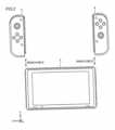
- Fig. 1 is a schematic diagram showing appearance of a game device 1 based on the present embodiment.
- game device 1 includes a main body apparatus 2, a left controller 3, and a right controller 4.
- Main body apparatus 2 includes a display 12 representing one example of a display portion and performs various types of processing including game processing in game device 1.
- Fig. 2 is a schematic diagram showing appearance of another manner of game device 1 based on the present embodiment.
- left controller 3 and right controller 4 may be constructed as being detachable from main body apparatus 2.
- Left controller 3 and right controller 4 may integrally be constructed or left controller 3 and right controller 4 may be constructed as separate apparatuses.
- left controller 3 and right controller 4 corresponding to an operation portion may be constructed separately from main body apparatus 2.
- Left controller 3 can be attached to a left side (a side of a positive direction of an x axis shown in Fig. 1 ) of main body apparatus 2.
- Right controller 4 can be attached to a right side (a side of a negative direction of the x axis shown in Fig. 1 ) of main body apparatus 2.
- left controller 3 and right controller 4 may collectively be referred to as a "controller”.
- a more specific configuration example of main body apparatus 2, left controller 3, and right controller 4 will be described below,
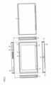
- Fig. 3 is a diagram of main body apparatus 2 based on the present embodiment when viewed from six sides.
- main body apparatus 2 has a housing 11 substantially in a form of a plate.
- a main surface of housing 11 (that is, a front surface or a surface where display 12 is provided) is substantially in a rectangular shape.
- housing 11 is in a horizontally long shape and a longitudinal direction of the main surface (that is, the direction of the x axis shown in Fig. 1 ) is referred to as a lateral direction (or a left-right direction) and a direction of a short side of the main surface (that is, a direction of a y axis shown in Fig. 1 ) is referred to as a vertical direction (or an up-down direction).
- a direction perpendicular to the main surface of housing 11 (that is, a direction of a z axis shown in Fig. 1 ) is referred to as a direction of depth (or a front-rear direction).
- Main body apparatus 2 can be used with its main surface being laterally oriented or with its surface being vertically oriented when a user holds the main body apparatus. Therefore, denotation as the lateral direction and the vertical direction is given for the sake of convenience of description.
- a shape and a size of housing 11 can arbitrarily be designed.
- a protrusion portion or a grip portion for facilitating holding by a user may be added to housing 11.
- display 12 is provided on the main surface of housing 11 of main body apparatus 2.
- Display 12 shows an image obtained or generated by main body apparatus 2 (which may be a still image or moving images).
- main body apparatus 2 which may be a still image or moving images.
- display 12 shows a virtual space and an object in the virtual space.
- display 12 is typically implemented by a liquid crystal display (LCD), a display apparatus of any type can be adopted.
- LCD liquid crystal display
- a touch panel 13 is provided on a screen of display 12.
- a device of a type accepting a multi-touch input for example, a capacitance type
- a device of any type such as a device of a type accepting a single-touch input (for example, a resistive film type) can be adopted as touch panel 13.
- Speaker holes 11a and 11b are provided in the main surface of housing 11 of main body apparatus 2 and sound generated from a speaker (a speaker 88 shown in Fig. 7 ) arranged in housing 11 is output through speaker holes 11a and 11b.
- Speaker hole 11a is provided on a left side of display 12 in correspondence with the left speaker and speaker hole 1 1b is provided on a right side of display 12 in correspondence with the right speaker.
- speaker holes 11a and 11b can arbitrarily be designed.
- speaker holes 11a and 11b may be provided in a side surface or a rear surface of housing 11.
- a left rail member 15 for removably attaching left controller 3 to main body apparatus 2 is provided in a left side surface of housing 11.
- Left rail member 15 extends along the up-down direction in the left side surface of housing 11.
- Left rail member 15 is in a shape allowing engagement thereof with a slider (a slider 40 shown in Fig. 4 ) for left controller 3.
- a slide mechanism is formed by left rail member 15 and slider 40. With such a slide mechanism, left controller 3 can slidably and removably be attached to main body apparatus 2.
- a left terminal 17 is provided in the left side surface of housing 11.
- Left terminal 17 is a terminal for wired communication between main body apparatus 2 and left controller 3.
- Left terminal 17 is provided at a position where it comes in contact with a terminal (a terminal 42 shown in Fig. 4 ) of left controller 3 when left controller 3 is attached to main body apparatus 2.
- Left terminal 17 should be arranged at a position where the left terminal of main body apparatus 2 and the terminal of left controller 3 are in contact with each other while left controller 3 is attached to main body apparatus 2.
- left terminal 17 is provided around a lower end portion of left rail member 15.
- a feature similar to the feature provided in the left side surface is provided in a right side surface of housing 11.
- a right rail member 19 for removably attaching right controller 4 to main body apparatus 2 is provided in the right side surface of housing 11.
- Right rail member 19 extends along the up-down direction in the right side surface of housing 11.
- Right rail member 19 is in a shape allowing engagement thereof with a slider (a slider 62 shown in Fig. 5 ) for right controller 4.
- a slide mechanism is formed by right rail member 19 and slider 62. With such a slide mechanism, right controller 4 can slidably and removably be attached to main body apparatus 2.
- Right rail member 19 is in a shape similar to left rail member 15.
- Right rail member 19 is in a grooved shape similar in cross-sectional shape to left rail member 15.
- Right rail member 19 does not have to be exactly the same in shape as left rail member 15.
- another embodiment may be constructed such that slider 62 for right controller 4 cannot be engaged with left rail member 15 and/or slider 40 for left controller 3 cannot be engaged with right rail member 19 by making a size and/or a shape of the groove different between left rail member 15 and right rail member 19.
- a right terminal 21 is provided in the right side surface of housing 11.
- Right terminal 21 is a terminal for wired communication between main body apparatus 2 and right controller 4.
- Right terminal 21 is provided at a position where it comes in contact with a terminal (a terminal 64 shown in Fig. 5 ) of right controller 4 when right controller 4 is attached to main body apparatus 2.
- Right terminal 21 should be arranged at any position where the right terminal of main body apparatus 2 and the terminal of right controller 4 are in contact with each other while right controller 4 is attached to main body apparatus 2.
- right terminal 21 is provided around a lower end portion of right rail member 19.
- a first slot 23 for attaching a storage medium of a first type is provided in an upper side surface of housing 11.
- a lid portion which can be opened and closed is provided in an opening in first slot 23 as a typical feature, and a storage medium of the first type can be inserted in first slot 23 while the lid portion is open.
- the storage medium of the first type is, for example, a storage medium exclusively designed for game device 1 and a game device of the same type (for example, a dedicated memory card).
- the storage medium of the first type is used, for example, for storing data used in main body apparatus 2 (for example, data saved for an application) and/or a program executed in main body apparatus 2 (for example, a program for an application).
- a power button 28 for switching on and off main body apparatus 2 is provided on the upper side surface of housing 11.
- An audio input and output terminal 25 (specifically an earphone jack) is provided in the upper side surface of housing 11.
- a microphone or an earphone can be attached to audio input and output terminal 25.
- a lower terminal 27 for wired communication between main body apparatus 2 and a cradle 5 which will be described later is provided in a lower side surface of housing 11.
- Lower terminal 27 is provided at a position where it comes in contact with a terminal of cradle 5 when main body apparatus 2 is attached to cradle 5.
- a universal serial bus (USB) connector (more specifically, a female connector) can be adopted as lower terminal 27.
- a second slot 24 for attaching a storage medium of a second type different from the first type is provided in the lower side surface of housing 11.
- Second slot 24 may be provided in the surface where first slot 23 is provided.
- a lid portion which can be opened and closed is provided in an opening in second slot 24 as a typical feature, and a storage medium of the second type can be inserted in second slot 24 while the lid portion is open.
- the storage medium of the second type may be, for example, a general-purpose storage medium (for example, an SD card).
- the storage medium of the second type is used, for example, for storing data used in main body apparatus 2 (for example, data saved for an application) and/or a program executed in main body apparatus 2 (for example, a program for an application), similarly to the storage medium of the first type.
- a position, a shape, and the number of components (specifically, a button, a slot, and a terminal) provided in housing 11 described above can arbitrarily be designed.
- some of power button 28, first slot 23, and second slot 24 may be provided in another side surface or the rear surface of housing 11. Some of the components do not have to be provided.
- Fig. 4 is a diagram of left controller 3 based on the present embodiment when viewed from six sides.
- left controller 3 has a housing 31 substantially in a form of a plate.
- a main surface of housing 31 (that is, a front surface or a surface on a side of a negative direction of the z axis shown in Fig. 1 ) is substantially in a rectangular shape.
- Housing 31 is in a vertically long shape, that is, long in the up-down direction (that is, the direction of the y axis shown in Fig. 1 ).
- Left controller 3 can be used with its main surface being vertically oriented or with its surface being horizontally oriented when a user holds the left controller while the left controller is detached from main body apparatus 2.
- Analog stick 32 is provided in left controller 3. As shown in Fig. 4 , analog stick 32 is provided on the main surface of housing 31. Analog stick 32 represents one example of a direction instruction portion with which a direction can be input. Analog stick 32 includes a stick member which can be tilted in all directions (that is, a 360° direction including up, down, left, right, and diagonal directions) in parallel to the main surface of housing 31. The analog stick is an analog input device with which a user can input a direction in accordance with a direction of tilt by titling the stick member. Analog stick 32 may further be constructed to be able to give an input of magnitude in accordance with an angle of tilt in addition to input of a direction in accordance with a direction of tilt when the stick member is tilted.
- a slide stick may implement the direction instruction portion.
- the slide stick is an input portion having a stick member slidable in all directions in parallel to the main surface of housing 31, and the user can give an input in accordance with a direction of slide by sliding the stick member.
- the slide stick may further be constructed also to give an input of magnitude in accordance with an amount of slide.
- the direction instruction portion may be implemented as an input portion indicating a direction through an operation to press a button.
- the direction instruction portion may be implemented as an input portion indicating a direction with a cross-shaped key or four buttons corresponding to up, down, left, and right directions, respectively.
- an input can be given by pressing the stick member (in the direction perpendicular to housing 31).
- Analog stick 32 in the present embodiment is an input portion with which an input of a direction and magnitude in accordance with a direction of tilt and an amount of tilt of the stick member can be given and an input resulting from pressing of the stick member can be given.
- Left controller 3 includes four operation buttons 33 to 36 (specifically, a right direction button 33, a down direction button 34, an up direction button 35, and a left direction button 36). As shown in Fig. 4 , these four buttons 33 to 36 are provided under analog stick 32 on the main surface of housing 31. Though four operation buttons are provided on the main surface of left controller 3 in the present embodiment, any number of operation buttons may be provided. These operation buttons 33 to 36 are used for giving an instruction in accordance with various programs (for example, an OS program or an application program) executed in main body apparatus 2.
- various programs for example, an OS program or an application program
- operation buttons 33 to 36 may be used for giving an input of a direction in the present embodiment, operation buttons 33 to 36 are also referred to as right direction button 33, down direction button 34, up direction button 35, and left direction button 36 for the sake of convenience of description. Operation buttons 33 to 36 may be used for giving an instruction other than an input of a direction.
- An operation portion (specifically, analog stick 32 and operation buttons 33 to 36) provided on the main surface of left controller 3 is operated, for example, with the left thumb of a user who holds game device 1 when left controller 3 is attached to main body apparatus 2.
- the operation portion is operated, for example, with the left thumb of the user who holds left controller 3.
- a first L button 38 and a ZL button 39 are provided in left controller 3. These operation buttons 38 and 39 are used for giving an instruction in accordance with various programs executed in main body apparatus 2, similarly to operation buttons 33 to 36 described above.
- first L button 38 is provided in an upper left portion on the side surface of housing 31.
- ZL button 39 is provided in an upper left portion as extending from the side surface to the rear surface of housing 31 (strictly speaking, the upper left portion when housing 31 is viewed from the front).
- ZL button 39 is provided in the rear of first L button 38 (a side of a positive direction of the z axis shown in Fig. 1 ). Since the upper left portion of housing 31 is rounded in the present embodiment, first L button 38 and ZL button 39 are in a rounded shape in conformity with rounding of the upper left portion of housing 31.
- first L button 38 and ZL button 39 are arranged in the upper left portion of game device 1 (see Fig. 1 ). Therefore, a user who holds game device 1 can operate first L button 38 and ZL button 39 with his/her left forefinger or long finger.
- Left controller 3 has terminal 42 for wired communication between left controller 3 and main body apparatus 2.
- Terminal 42 is provided at a position where it comes in contact with left terminal 17 ( Fig. 3 ) of main body apparatus 2 when left controller 3 is attached to main body apparatus 2.
- Terminal 42 should be arranged at any position where main body apparatus 2 and left controller 3 are in contact with each other while left controller 3 is attached to main body apparatus 2.
- terminal 42 is provided around a lower end portion of the surface where slider 40 is attached.
- Left controller 3 includes a second L button 43 and a second R button 44. These buttons 43 and 44 are used for giving an instruction in accordance with various programs executed in main body apparatus 2 similarly to other operation buttons 33 to 36.
- second L button 43 and second R button 44 are provided in the surface where slider 40 is attached.
- Second L button 43 is provided above the center in terms of the up-down direction (the direction of the y axis shown in Fig. 1 ) on the surface where slider 40 is attached.
- Second R button 44 is provided under the center in terms of the up-down direction on the surface where slider 40 is attached.
- Second L button 43 and second R button 44 are arranged at positions where they cannot be pressed while left controller 3 is attached to main body apparatus 2.
- Second L button 43 and second R button 44 are used while left controller 3 is detached from main body apparatus 2.
- Second L button 43 and second R button 44 are operated, for example, with a forefinger or a long finger of left and right hands of a user who holds left controller 3 detached from main body apparatus 2.
- Fig. 5 is a diagram of right controller 4 based on the present embodiment when viewed from six sides.
- right controller 4 has a housing 51 substantially in a form of a plate.
- a main surface of housing 51 (that is, a front surface or a surface on the side of the negative direction of the z axis shown in Fig. 1 ) is substantially in a rectangular shape.
- Housing 51 is in a vertically long shape, that is, long in the up-down direction.
- Right controller 4 can be used with its main surface being vertically oriented or with its surface being horizontally oriented when a user holds the right controller while the right controller is detached from main body apparatus 2.
- An analog stick 52 is provided in right controller 4 as a direction instruction portion as in left controller 3.
- Analog stick 52 is constructed substantially similarly to analog stick 32 in left controller 3.
- Right controller 4 includes four operation buttons 53 to 56 (specifically, an A button 53, a B button 54, an X button 55, and a Y button 56) similarly to left controller 3. These four operation buttons 53 to 56 are substantially the same in mechanism as four operation buttons 33 to 36 in left controller 3.
- analog stick 52 and operation buttons 53 to 56 are provided on the main surface of housing 51. Though four operation buttons are provided on the main surface of right controller 4 in the present embodiment, any number of operation buttons may be provided.
- right controller 4 When right controller 4 is attached to main body apparatus 2, the operation portion (specifically analog stick 52 and operation buttons 53 to 56) provided on the main surface of right controller 4 is operated, for example, with the right thumb of a user who holds game device 1.
- the operation portion When right controller 4 is used as being detached from main body apparatus 2, the operation portion is operated, for example, with the right thumb of a user who holds right controller 4.
- a first R button 60 and a ZR button 61 are provided in right controller 4. As shown in Fig. 5 , first R button 60 is provided in an upper right portion on the side surface of housing 51. ZR button 61 is provided in an upper right portion as extending from the side surface to the rear surface of housing 51 (strictly speaking, the upper right portion when housing 51 is viewed from the front). ZR button 61 is provided in the rear of first R button 60 (the side of the positive direction of the z axis shown in Fig. 1 ). Since the upper right portion of housing 51 is rounded in the present embodiment, first R button 60 and ZR button 61 are in a rounded shape in conformity with rounding of the upper right portion of housing 51.
- first R button 60 and ZR button 61 are arranged in the upper right portion of game device 1 (see Fig. 1 ). Therefore, a user who holds game device 1 can operate first R button 60 and ZR button 61 with his/her right forefinger or long finger.
- Right controller 4 has terminal 64 for wired communication between right controller 4 and main body apparatus 2.
- Terminal 64 is provided at a position where it comes in contact with right terminal 21 ( Fig. 3 ) of main body apparatus 2 when right controller 4 is attached to main body apparatus 2.
- Terminal 64 should be arranged at any position where main body apparatus 2 and right controller 4 are in contact with each other while right controller 4 is attached to main body apparatus 2.
- terminal 64 is provided around a lower end portion of the surface where slider 62 is attached.
- a position, a shape, and the number of components provided in housing 31 of left controller 3 and/or housing 51 of right controller 4 can arbitrarily be designed.
- the controller may include a direction instruction portion of a type different from the analog stick.
- Slider 40 or 62 may be arranged at a position in accordance with a position of left rail member 15 and right rail member 19 provided in main body apparatus 2, and for example, may be arranged in the main surface or the rear surface of housing 31 or 51.
- Right controller 4 includes a second L button 65 and a second R button 66 as in left controller 3. These buttons 65 and 66 are used for giving an instruction in accordance with various programs executed in main body apparatus 2 similarly to other operation buttons 53 to 56. As shown in Fig. 5 , second L button 65 and second R button 66 are provided on a surface where slider 62 is attached. Second L button 65 is provided under the center in terms of the up-down direction (the direction of the y axis shown in Fig. 1 ) on the surface where slider 62 is attached. Second R button 66 is provided above the center in terms of the up-down direction on the surface where slider 62 is attached.
- Second L button 65 and second R button 66 are arranged at positions where they cannot be pressed while right controller 4 is attached to main body apparatus 2. Second L button 65 and second R button 66 are used while right controller 4 is detached from main body apparatus 2. Second L button 65 and second R button 66 are operated, for example, with a forefinger or a long finger of left and right hands of a user who holds right controller 4 detached from main body apparatus 2.
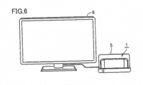
- Fig. 6 is a schematic diagram showing appearance when game device 1 based on the present embodiment is used together with a cradle.
- the game system shown in Fig. 6 includes game device 1 and cradle 5.
- Cradle 5 is constructed to be able to carry game device 1 and constructed to be able to communicate with a television 6 representing one example of an external display apparatus separate from display 12 of game device 1.
- a television 6 representing one example of an external display apparatus separate from display 12 of game device 1.
- Communication between cradle 5 and television 6 may be wired communication or wireless communication.
- Cradle 5 may have a function to charge placed game device 1 and a function as a communication hub apparatus (for example, a USB hub).
- a communication hub apparatus for example, a USB hub
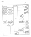
- Fig. 7 is a block diagram showing an internal configuration of main body apparatus 2 based on the present embodiment.
- Main body apparatus 2 includes components shown in Fig. 7 .
- the components shown in Fig. 7 are accommodated in housing 11, for example, as being mounted on an electronic circuit substrate as electronic components.
- Main body apparatus 2 includes a central processing unit (CPU) 81 corresponding to an information processing unit (or a processor) performing various types of processing including game processing.
- CPU 81 reads and executes a program stored in an accessible storage unit (specifically, an internal storage medium such as a flash memory 84 or an external storage medium attached to first slot 23 or second slot 24).
- an accessible storage unit specifically, an internal storage medium such as a flash memory 84 or an external storage medium attached to first slot 23 or second slot 24.
- Main body apparatus 2 includes flash memory 84 and a dynamic random access memory (DRAM) 85 by way of example of an embedded internal storage medium.
- Flash memory 84 is a non-volatile memory mainly storing various types of data (which may be a program) saved in main body apparatus 2.
- DRAM 85 is a volatile memory temporarily storing various types of data used in information processing.
- Main body apparatus 2 includes a first slot interface (I/F) 91 and a second slot interface 92.
- the first slot interface is connected to first slot 23 and reads and writes data from and into a storage medium of the first type (for example, an SD card) attached to first slot 23, in response to an instruction from CPU 81.
- Second slot interface 92 is connected to second slot 24 and reads and writes data from and into a storage medium of the second type (for example, a dedicated memory card) attached to second slot 24, in response to an instruction from CPU 81.
- Main body apparatus 2 includes a network communication unit 82 for communication (specifically, wireless communication) with an external apparatus through a network.
- a communication module authorized for Wi-Fi is employed for network communication unit 82 and network communication unit 82 communicates with an external apparatus through wireless LAN.
- main body apparatus 2 may have a function for connection and communication with a mobile communication network (that is, a portable telephone communication network) in addition to (or instead of) a function for connection and communication with wireless LAN.
- Main body apparatus 2 includes a controller communication unit 83 for wireless communication with left controller 3 and/or right controller 4. Though any scheme is applicable for communication between main body apparatus 2 and each controller, for example, a communication scheme under the Bluetooth TM specifications can be adopted.
- CPU 81 is connected to left terminal 17, right terminal 21, and lower terminal 27.
- CPU 81 transmits and receives data to and from left controller 3 through left terminal 17 when wired communication with left controller 3 is established.
- CPU 81 transmits and receives data to and from right controller 4 through right terminal 21 when wired communication with right controller 4 is established.
- Data transmitted from CPU 81 to left controller 3 or right controller 4 is, for example, data for controlling a vibration generation portion of left controller 3 or right controller 4.
- Data received by CPU 81 from left controller 3 or right controller 4 is, for example, operation data output in response to an operation by a user of the operation portion in left controller 3 or right controller 4.
- CPU 81 transmits data to cradle 5 through lower terminal 27 when it communicates with cradle 5.
- main body apparatus 2 can establish both of wired communication and wireless communication with left controller 3 and right controller 4.
- Main body apparatus 2 includes a touch panel controller 86 for control of touch panel 13.
- Touch panel controller 86 generates data indicating a position of a touch input in response to a signal from touch panel 13, and outputs the data to CPU 81.
- Display 12 shows an image generated by execution of various types of processing by CPU 81 and/or an image obtained from the outside.
- Main body apparatus 2 includes a codec circuit 87 and speaker 88 (specifically, the left speaker and the right speaker).
- Codec circuit 87 controls input and output of audio data to and from speaker 88 and audio input and output terminal 25. More specifically, when codec circuit 87 receives audio data from CPU 81, it outputs an audio signal resulting from D/A conversion of the audio data to speaker 88 or audio input and output terminal 25. Thus, sound is output from speaker 88 or an audio output portion (for example, an earphone) connected to audio input and output terminal 25.
- codec circuit 87 receives an audio signal from audio input and output terminal 25, it subjects the audio signal to AID conversion and outputs audio data in a prescribed format to CPU 81.
- Main body apparatus 2 includes an electric power control unit 97 and a battery 98.
- Electric power control unit 97 controls supply of electric power from battery 98 to each component based on a command from CPU 81.
- Electric power control unit 97 controls supply of electric power in accordance with an input onto power button 28.
- electric power control unit 97 stops supply of electric power totally or in part, and when an operation to turn on power supply is performed on power button 28, it starts full supply of electric power.
- electric power control unit 97 stops supply of electric power to some components including display 12, and when an instruction to switch to an ON mode is given to power button 28, it starts supply of electric power.
- Battery 98 of main body apparatus 2 is preferably higher in charging capacity than a battery of left controller 3 and right controller 4.
- Battery 98 is connected to left terminal 17 and right terminal 21.
- left controller 3 When left controller 3 is connected to main body apparatus 2, electric power is fed from battery 98 of main body apparatus 2 to left controller 3 through left terminal 17.
- right controller 4 When right controller 4 is attached to main body apparatus 2, electric power is fed from battery 98 of main body apparatus 2 to right controller 4 through right terminal 21.
- Fig. 8 is a block diagram showing an internal configuration of left controller 3 and right controller 4 based on the present embodiment
- Fig. 8 also depicts components of main body apparatus 2 associated with left controller 3 and right controller 4.
- Left controller 3 includes a communication control unit 101 for communication with main body apparatus 2.
- Communication control unit 101 can communicate with main body apparatus 2 through both of wired communication through terminal 42 and wireless communication not through terminal 42.
- Terminal 42 includes a communication terminal 42A used for communication, a power supply terminal 42B used for power feed, and an identification terminal 42C used for detection of a connected device.
- Terminal 42 is provided as being connectable to left terminal 17 of main body apparatus 2.
- Left terminal 17 includes a communication terminal 17A used for communication, a power supply terminal 17B used for power feed, and an identification terminal 17C used for detection of a connected device.
- communication terminal 42A and communication terminal 17A are electrically connected to each other.
- Power supply terminal 42B and power supply terminal 17B are electrically connected to each other.
- Identification terminal 42C and identification terminal 17C are electrically connected to each other.
- Communication control unit 101 selects wired communication or wireless communication depending on whether or not left controller 3 is attached to main body apparatus 2, and establishes communication under a selected communication method. While left controller 3 is attached to main body apparatus 2, communication control unit 101 establishes communication with main body apparatus 2 through communication terminal 42A. While left controller 3 is detached from main body apparatus 2, communication control unit 101 establishes wireless communication with main body apparatus 2 (specifically, controller communication unit 83). Communication control unit 101 should only be able to establish communication with main body apparatus 2, and for example, it may be configured to establish only either wired communication or wireless communication. While left controller 3 is detached from main body apparatus 2, wireless communication is established by way of example, however, wired communication may be established, for example, through a cable.
- Left controller 3 includes, for example, a memory 102 such as a flash memory.
- Communication control unit 101 is implemented, for example, by a microprocessor and performs various types of processing by executing firmware stored in memory 102.
- Left controller 3 includes an operation button group 103 (specifically operation buttons 33 to 36, 38, and 39) and analog stick 32. Information on an operation onto operation button group 103 and analog stick 32 is repeatedly output to communication control unit 101 with a prescribed period.
- Communication control unit 101 obtains information on an input from each of operation button group 103 and analog stick 32 (for example, information on an operation by a user). Communication control unit 101 transmits data including obtained information (or information obtained by subjecting obtained information to prescribed processing) to main body apparatus 2. Data is transmitted to main body apparatus 2 repeatedly with a prescribed period. A period of transmission of information on an input to main body apparatus 2 may or may not be identical among input devices.
- Main body apparatus 2 can know an input given to left controller 3 based on transmitted data. More specifically, main body apparatus 2 can discriminate an operation onto operation button group 103 and analog stick 32.
- Left controller 3 includes an electric power supply unit 109 including a battery. Electric power supply unit 109 controls supply of electric power to each component of left controller 3. When left controller 3 is attached to main body apparatus 2, the battery is charged by power feed from main body apparatus 2 through power supply terminal 42B.
- Right controller 4 is configured basically similarly to left controller 3 described above.
- Right controller 4 includes terminal 64, a communication control unit 111, a memory 112, an operation button group 113 (specifically operation buttons 53 to 56, 60, and 61), analog stick 52, and an electric power supply unit 119.
- Terminal 64 includes a communication terminal 64A used for communication, a power supply terminal 64B used for power feed, and an identification terminal 64C used for detection of a connected device.
- Terminal 64 is provided as being connectable to right terminal 21 of main body apparatus 2.
- Right terminal 21 includes a communication terminal 21A used for communication, a power supply terminal 21B used for power feed, and an identification terminal 21C used for detection of a connected device.
- communication terminal 21A and communication terminal 64A are electrically connected to each other.
- Power supply terminal 21B and power supply terminal 64B are electrically connected to each other.
- Identification terminal 21C and identification terminal 64C are electrically connected to each other.
- Communication control unit 111 selects wired communication or wireless communication depending on whether or not right controller 4 is attached to main body apparatus 2, and establishes communication under a selected communication method. When right controller 4 is attached to main body apparatus 2, communication control unit 111 establishes communication with main body apparatus 2 through communication terminal 64A.
- Right controller 4 includes electric power supply unit 119 including a battery. Electric power supply unit 119 controls supply of electric power to each component of right controller 4. While right controller 4 is attached to main body apparatus 2, the battery is charged by power feed from main body apparatus 2 through power supply terminal 64B.
- a first terminal that is, left terminal 17 or right terminal 21
- a second terminal that is, terminal 42 or 64
- the controller can also include a vibration mechanism, an acceleration sensor, and a gyro sensor.
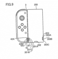
- Fig. 9 is a diagram illustrating an expansion battery 200 which can be connected to the controller based on an embodiment.
- expansion battery 200 is connected to left controller 3
- Expansion battery 200 is provided to be able to supply electric power to left controller 3.
- a terminal 201 which can electrically be connected to left controller 3 is provided in expansion battery 200.
- Terminal 201 includes a communication terminal 201A used for communication, a power supply terminal 201B used for power feed, and an identification terminal 201C used for detection of a connected device. As terminal 42 and terminal 201 are connected to each other, communication terminal 42A and communication terminal 201A are electrically connected to each other. Power supply terminal 42B and power supply terminal 201B are electrically connected to each other. Identification terminal 42C and identification terminal 201C are electrically connected to each other.
- An LED 202 indicating a state of charge to left controller 3 is provided in expansion battery 200.
- Terminal 203 which can electrically be connected to right controller 4 is provided in expansion battery 200.
- Terminal 203 includes a communication terminal 203A, a power supply terminal 203B used for power feed, and an identification terminal 203C used for detection of a connected device.
- communication terminal 64A and communication terminal 203A are electrically connected to each other.
- Power supply terminal 64B and power supply terminal 203B are electrically connected to each other.
- Identification terminal 64C and identification terminal 203C are electrically connected to each other.
- LED 202 emits light during charging of right controller 4 as in left controller 3.
- Fig. 10 is a diagram illustrating a circuit configuration of left controller 3 and expansion battery 200 based on the embodiment.
- electric power supply unit 109 is provided in left controller 3.
- Electric power supply unit 109 includes a voltage detector 105, a state-of-charge sensing unit 106, a current regulator 107, a resistor R1, a battery V1, a diode D1, and switches SW1 and SW2.
- a node N1 is connected to identification terminal 42C with resistor R1 being interposed.
- a node N0 is connected to power supply terminal 42B.
- Diode D1 has an anode connected to node N0 and a cathode connected to node N1 with current regulator 107 being interposed.
- Current regulator 107 is provided between diode D1 and node N1.
- Battery V1 is connected between node N1 and a ground voltage GND.
- Switch SW1 is connected between a node N2 and node N0.
- Switch SW2 is connected between node N2 and node N1.
- Voltage detector 105 is connected to node N0. Switches SW1 and SW2 are controlled in accordance with an instruction from communication control unit 101.
- Node N2 is connected to a power supply line so that electric power necessary for each unit is supplied.
- State-of-charge sensing unit 106 is provided in correspondence with battery V1, and senses a state of charge of battery V1 and outputs the state of charge to communication control unit 101.
- Expansion battery 200 includes a battery V2, a diode D2, a resistor R2, LED 202, and a switch SW3.
- Resistor R2 is connected between identification terminal 201C and ground voltage GND.
- Diode D2 is connected in series between power supply terminal 201B and a node N3.
- Diode D2 has an anode connected to node N3 and a cathode connected to power supply terminal 201B.
- Battery V2 is connected between node N3 and ground voltage GND.
- Switch SW3 and LED 202 are connected in series between node N3 and ground voltage GND. Switch SW3 is controlled in accordance with an instruction from communication control unit 101.
- Communication control unit 101 includes a discrimination unit 120, a switch control unit 122, a processing execution unit 124, a communication unit 126, and a light emission control unit 128.
- Discrimination unit 120 discriminates a device connected to terminal 42 based on a voltage value detected by voltage detector 105. Discrimination unit 120 outputs a control signal CT for regulating a current to current regulator 107.
- Switch control unit 122 controls switching of switches SW1 and SW2 in accordance with a result of discrimination by discrimination unit 120. For example, when no device is connected to terminal 42, switch control unit 122 turns on switch SW2. Thus, battery V1 is connected to the power supply line and electric power necessary for each unit is supplied. When discrimination as connection of a connected device is made in accordance with a result of discrimination by discrimination unit 120 while electric power necessary for each unit is supplied from battery V1, switch control unit 122 turns off switch SW2 and turns on switch SW1 Battery V1 and the power supply line are thus electrically connected and disconnected to and from each other. As switch SW1 is turned on, terminal 42 and the power supply line are electrically connected to each other and power can be fed through terminal 42.
- Communication unit 126 performs processing for wireless communication and processing for wired communication with an external device.
- communication unit 126 transmits attachment information on another attached apparatus to main body apparatus 2.
- communication unit 126 transmits attachment information (an identification code) based on a result of discrimination by discrimination unit 120 to main body apparatus 2.
- attachment information an identification code
- communication unit 126 can also transmit attachment information (an identification code) indicating absence of attachment.
- Processing execution unit 124 performs prescribed processing in accordance with an instruction from an external device received at communication unit 126.
- Light emission control unit 128 controls the LED provided in the device based on a result of discrimination by discrimination unit 120 and a result of sensing by state-of-charge sensing unit 106. In the present example, a command to turn on switch SW3 is output.
- identification terminal 42C of left controller 3 and identification terminal 201C of expansion battery 200 are electrically connected to each other.
- Power supply terminal 42B of left controller 3 and power supply terminal 201B of expansion battery 200 are electrically connected to each other.
- Communication terminal 42A of left controller 3 and communication terminal 201A of expansion battery 200 are electrically connected to each other.
- Voltage detector 105 detects a voltage based on division of resistances of resistor R1 and resistor R2 as a result of formation of the current path.
- Discrimination unit 120 detects a connected device based on a detected voltage value and discriminates the connected device.
- a resistance value of resistor R2 is different depending on a type of a connected device connected to the controller. Therefore, a voltage value detected by voltage detector 105 is different depending on a type of a device.
- Discrimination unit 120 instructs switch control unit 122 to switch based on a result of discrimination.
- Switch control unit 122 gives an instruction to turn off switch SW2 and turn on switch SW1. Accordingly, instead of battery V1, battery V2 supplies electric power to each unit in left controller 3.
- Battery V1 is chargeable and dischargeable, As switch SW is switched by switch control unit 122, battery V1 is charged as a result of supply of electric power from battery V2 when electric power is supplied from battery V2 to each unit in left controller 3.
- Current regulator 107 regulates a charging current in charging of battery V1 from battery V2. Specifically, a charging current for battery V1 is regulated in accordance with control signal CT from discrimination unit 120.
- Light emission control unit 128 outputs a command signal for having the LED emit light based on a result of discrimination by discrimination unit 120 and a result of sensing by state-of-charge sensing unit 106.
- the command signal is input to switch SW3 through communication terminal 42A and communication terminal 201A from communication control unit 101.
- light emission control unit 128 outputs a command signal to turn on switch SW3 when a connected device is discriminated as a device having an LED as a result of discrimination by discrimination unit 120 and battery V1 is in a prescribed state of charge.
- the prescribed state of charge refers to battery V1 not being fully charged by way of example.
- battery V1 is not charged by battery V2.
- light emission control unit 128 does not output a command signal to turn on switch SW3 and hence LED 202 does not emit light. Therefore, fully charged battery V1 can easily be recognized.
- light emission control unit 128 outputs a command signal to turn on switch SW3 and LED 202 emits light, battery V1 being charged can easily be recognized.
- expansion battery 200 may be removed and attached from and to left controller 3 based on a state of emission of light by LED 202.
- light emission control unit 128 outputs a command signal for having the LED emit light based on a result of discrimination by discrimination unit 120 and a result of sensing by state-of-charge sensing unit 106.
- a command signal for having the LED emit light only in accordance with a result of discrimination by discrimination unit 120 may be output.
- a connection state can easily be checked.
- a connected device described below is also similar in circuit configuration or in configuration of the battery and the LED to expansion battery 200.
- a resistance value of resistor R2 is different depending on a type of a connected device.
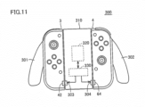
- Fig. 11 is a diagram of appearance of an expansion grip 300 based on the embodiment.
- Expansion grip 300 for attaching left controller 3 and right controller 4 detached from main body apparatus 2 is shown in Fig. 11 .
- Expansion grip 300 represents one example of a connected device to which a controller can be attached.
- Expansion grip 300 is a connected device with which a user performs an operation.
- Expansion grip 300 includes a housing 310. Left controller 3 and right controller 4 can be attached to housing 310. Therefore, with expansion grip 300, a user can perform an operation as integrally holding two controllers of left controller 3 and right controller 4 detached from main body apparatus 2. Expansion grip 300 has a mechanism similar to the mechanism of main body apparatus 2 as the mechanism for attachment of the controller. Therefore, left controller 3 and right controller 4 can be attached to expansion grip 300 as in attachment of main body apparatus 2.
- Expansion grip 300 has a grip portion for a user to hold. Specifically, left controller 3 is attached to expansion grip 300 on the left of the center in the lateral direction. Expansion grip 300 includes a left grip portion 301 on the left of a portion where left controller 3 is attached. Right controller 4 is attached to expansion grip 300 on the right of the center in terms of the lateral direction. Expansion grip 300 includes a right grip portion 302 on the right of a portion where right controller 4 is attached. Therefore, a user can easily operate each of left controller 3 and right controller 4 attached to expansion grip 300 by holding grip portions 301 and 302.
- Expansion grip 300 has a left terminal 303 similar to left terminal 17 of main body apparatus 2 at a position where connection with terminal 42 of left controller 3 attached to the expansion grip itself can be made.
- Expansion grip 300 has a right terminal 304 similar to right terminal 21 of main body apparatus 2 at a position where connection with terminal 64 of right controller 4 attached to the expansion grip itself can be made. Therefore, when left controller 3 and right controller 4 are attached to expansion grip 300, expansion grip 300 is electrically connected to left controller 3 and right controller 4.
- Left terminal 303 and right terminal 304 each include a communication terminal, a power supply terminal, and an identification terminal which can be connected to the communication terminal, the power supply terminal, and the identification terminal of terminals 42 and 64, respectively, similarly to terminals 201 and 203 of expansion battery 200.
- expansion grip 300 includes a power supply terminal similar to a power supply terminal of cradle 5. Therefore, expansion grip 300 can receive power feed through the power supply terminal from a not-shown charging apparatus (such as an AC adapter) when the charging apparatus is connected to the power supply terminal. Expansion grip 300 supplies electric power supplied through the power supply terminal to left controller 3 and right controller 4 through the left terminal and the right terminal.
- a not-shown charging apparatus such as an AC adapter
- expansion grip 300 has a function to charge the controller attached to the expansion grip itself.
- Expansion grip 300 includes charging means (that is, the power supply terminal and the left terminal or the right terminal) for charging the controller attached to expansion grip 300 with electric power fed to expansion grip 300.
- the controller can be charged while the controller is attached to the expansion grip.
- convenience of the controller can be improved.
- left controller 3 and right controller 4 are attached to expansion grip 300, wireless communication is established between each of left controller 3 and right controller 4 and main body apparatus 2 (as in the example in which left controller 3 and right controller 4 are detached from main body apparatus 2). Even while the controller is attached to expansion grip 300, left controller 3 and right controller 4 can communicate with main body apparatus 2.
- Expansion grip 300 contains a microcomputer (CPU) 320 and a communication unit 330.
- Left controller 3 and right controller 4 obtain apparatus identification information indicating attachment to expansion grip 300, which is transmitted from microcomputer 320 through communication unit 330, when the controller is attached to expansion grip 300.
- the apparatus identification information is, for example, identification information provided for each apparatus (more specifically, identification information specific to an apparatus).
- the apparatus identification information includes information indicating a type of an apparatus so that a type of the apparatus can be specified based on the apparatus identification information.
- the controller can determine (or sense) that an apparatus to which the controller is attached is expansion grip 300, that is, attachment of the controller itself to expansion grip 300, based on the identification information.
- the controller transmits a notification about detachment from expansion grip 300 through wireless communication to main body apparatus 2.
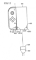
- Fig. 12 is a diagram illustrating a trial play stand expansion battery 400 which can be connected to the controller based on the embodiment.
- trial play stand expansion battery 400 is connected to left controller 3.
- Trial play stand expansion battery 400 is provided to be able to supply electric power to left controller 3.
- trial play stand expansion battery 400 is provided with a terminal 401 which can electrically be connected to left controller 3.
- Terminal 401 includes a power supply terminal 401B used for power feed and an identification terminal 401C used for detection of a connected device. As a result of connection between terminal 42 and terminal 401, power supply terminal 42B and power supply terminal 401B are electrically connected to each other. Identification terminal 42C and identification terminal 401C are electrically connected to each other.
- Trial play stand expansion battery 400 is provided with a terminal 403 which can electrically be connected to right controller 4.
- Terminal 403 includes a power supply terminal 403B used for power feed and an identification terminal 403C used for detection of a connected device.
- power supply terminal 64B and power supply terminal 403B are electrically connected to each other.
- Identification terminal 64C and identification terminal 403C are electrically connected to each other.
- Trial play stand expansion battery 400 is connected to an AC plug terminal 402 and an AC adapter 404.
- AC plug terminal 402 can be connected to a connector of an AC power supply.
- AC adapter 404 converts AC power supply to DC power supply so as to supply electric power to trial play stand expansion battery 400.
- trial play stand expansion battery 400 can constantly receive power feed from the AC power supply.
- Trial play stand expansion battery 400 supplies electric power to left controller 3 and right controller 4 through terminal 401 and/or terminal 403.
- Fig. 13 is a diagram illustrating a fixed expansion battery 500 which can be connected to a plurality of controllers based on the embodiment.
- fixed expansion battery 500 is provided to be able to supply electric power to a plurality of controllers.
- two left controllers 3 and two right controller 4 can be connected.
- Fixed expansion battery 500 is provided to be able to supply electric power to a plurality of left controllers 3 and a plurality of right controllers 4.
- Terminals 501 and 511 which can be connected to left controller 3 and terminals 503 and 513 which can be connected to right controller 4 are provided. Terminals 501, 511, 503, and 513 are connected to an electric power supply unit 510 provided with a battery.
- Each terminal includes a communication terminal, a power supply terminal, and an identification terminal which can be connected to the communication terminal, the power supply terminal, and the identification terminal, respectively, of terminal 42 or 64, similarly to terminal 201 or 203 of expansion battery 200.
- fixed expansion battery 500 includes a power supply terminal similar to the power supply terminal of cradle 5. Therefore, fixed expansion battery 500 can receive power feed through the power supply terminal from a not-shown charging apparatus (such as an AC adapter) by connecting the charging apparatus to the power supply terminal. Fixed expansion battery 500 supplies electric power supplied through the power supply terminal to left controller 3 and right controller 4 through the terminal.
- a plurality of LEDs indicating a state of charge are provided in fixed expansion battery 500.
- the fixed expansion battery includes an LED 502 indicating a state of charge of the controller connected to terminal 501, an LED 504 indicating a state of charge of the controller connected to terminal 503, an LED 506 indicating a state of charge of the controller connected to terminal 511, and an LED 508 indicating a state of charge of the controller connected to terminal 513.
- Emission of light from the LED is controlled under a scheme the same as above through the communication terminal used for communication.
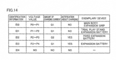
- Fig. 14 is a diagram illustrating a discrimination table used by discrimination unit 120 based on the embodiment.
- a discrimination table may be stored in advance in memories 102 and 112.
- the discrimination table is provided with a plurality of pieces of identification information ID0 to ID4 (identification codes).
- ID0 to ID4 identification codes
- a voltage value, an amount of a charging current, a notification about charging, and an exemplary device are set in association with identification information.
- the exemplary device is given as an item for illustration and such information does not have to be stored.
- a voltage value (P0 to P1), an amount of a charging current Q1, a notification about charging (no), and an exemplary device are set in association with identification information ID0.
- a voltage value (P1 to P2), amount of a charging current Q1, a notification about charging (no), and an exemplary device (a trial play stand expansion battery) are set in association with identification information ID1.
- a voltage value (P2 to P3), an amount of a charging current Q2 ( ⁇ Q1), a notification about charging (yes), and an exemplary device (a fixed expansion battery) are set in association with identification information ID2.
- a voltage value (P3 to P4), amount of a charging current Q1, a notification about charging (yes), and an exemplary device (an expansion battery) are set in association with identification information ID3.
- Identification information ID4 is an item indicating connection of no device, and nothing is set as a voltage value, an amount of a charging current, a notification about charging, and an exemplary device.
- a connected device connected to a controller is identified based on a result of detection by voltage detector 105 described above.
- a resistance value of resistor R2 described with reference to Fig. 10 is different for each device.
- resistor R2 of each of main body apparatus 2 and expansion grip 300 is set to have a resistance value at which a voltage value within a range from P0 to P1 is detected in attachment to the controller.
- Resistor R2 of trial play stand expansion battery 400 is set to have a resistance value at which a voltage value within a range from P1 to P2 is detected in attachment to the controller.
- Resistor R2 of fixed expansion battery 500 is set to have a resistance value at which a voltage value within a range from P2 to P3 is detected in attachment to the controller.
- Resistor R2 of expansion battery 200 is set to have a resistance value at which a voltage value within a range from P3 to P4 is detected in attachment to the controller.
- Voltage detector 105 detects a voltage value within the range from P3 to P4 when expansion battery 200 is connected to the controller.
- Discrimination unit 120 identifies a connected device as the expansion battery corresponding to identification information ID3 by using the discrimination table based on the voltage value.
- Discrimination unit 120 instructs switch control unit 122 to switch conducting switch SW2 to switch SW1 based on a result of discrimination. Accordingly, the controller operates by receiving power feed from expansion battery 200.
- Discrimination unit 120 outputs control signal CT to current regulator 107 such that amount of a charging current Q1 is attained based on a result of discrimination.
- current regulator 107 regulates the amount of the charging current in charging of the battery of the controller from expansion battery 200.
- Light emission control unit 128 controls LED 202 provided in expansion battery 200 based on a result of discrimination by discrimination unit 120 and a result of sensing by state-of-charge sensing unit 106. Specifically, since the item of the notification about charging corresponding to identification information ID3 indicates "yes", light emission control unit 128 recognizes that an LED for giving a notification about charging is provided. Then, when light emission control unit 128 determines that battery V1 is fully charged based on a result of sensing by state-of-charge sensing unit 106, it does not output a command signal to turn on switch SW3. When light emission control unit 128 determines that battery V1 is not fully charged based on a result of sensing by state-of-charge sensing unit 106, it outputs a command signal to turn on switch SW3. Accordingly, LED 202 emits light.
- Communication unit 126 transmits identification information ID3 to main body apparatus 2 as a result of discrimination by discrimination unit 120.
- Controller communication unit 83 of main body apparatus 2 obtains identification information ID3 transmitted from communication unit 126. Then, the information is given from controller communication unit 83 of main body apparatus 2 to CPU 81.
- CPU 81 can recognize connection of expansion battery 200 to the controller in accordance with obtained identification information ID3. On the side of main body apparatus 2, CPU 81 performs information processing upon receiving the information.
- CPU 81 can perform prescribed representation processing by way of example of information processing. Specifically, information on expansion battery 200 may be shown on display 12 in accordance with identification information ID3. CPU 81 may adjust a parameter for operation data transmitted from the controller by way of another example of information processing, because operational feeling of the controller may be different between before and after connection of expansion battery 200.
- Main body apparatus 2 may instruct the controller to perform prescribed processing depending on a recognized connected device.
- CPU 81 may give an instruction to change some of functions of the controller in accordance with obtained identification information ID3.
- CPU 81 may output an order to stop a vibration mechanism when the controller is provided with the vibration mechanism.
- Communication unit 126 of the controller receives the order and outputs the order to processing execution unit 124.
- Processing execution unit 124 may change to setting for not using the vibration mechanism based on the order transmitted from main body apparatus 2.
- voltage detector 105 detects a voltage value within the range from P0 to P1.
- the controller When the controller is connected to expansion grip 300, the controller obtains apparatus identification information from microcomputer 320 of expansion grip 300 through communication unit 330.
- Discrimination unit 120 identifies a connected device as an expansion grip corresponding to identification information ID0 based on the detected voltage value and the apparatus identification information (identification information specific to the expansion grip) by using the discrimination table.
- discrimination unit 120 identifies a connected device as the expansion grip corresponding to identification information ID0 based on the detected voltage value and the apparatus identification information, however, determination may be made based on any one of them.
- Discrimination unit 120 instructs switch control unit 122 to switch conducting switch SW2 to switch SW1 based on a result of discrimination. Accordingly, the controller operates by receiving power feed from expansion grip 300.
- Discrimination unit 120 outputs control signal CT to current regulator 107 such that amount of a charging current Q1 is attained based on a result of discrimination.
- current regulator 107 regulates the amount of the charging current in charging of the battery of the controller from expansion grip 300.
- expansion grip 300 is provided with no LED, light emission control unit 128 does not output a command signal.
- Communication unit 126 transmits identification information ID0 and apparatus identification information to main body apparatus 2 as a result of discrimination by discrimination unit 120.
- Controller communication unit 83 of main body apparatus 2 obtains identification information ID0 and the apparatus identification information transmitted from communication unit 126. Then, the information is given from controller communication unit 83 of main body apparatus 2 to CPU 81.
- CPU 81 can recognize connection of expansion grip 300 to the controller in accordance with obtained identification information IDd and the apparatus identification information. On the side of main body apparatus 2, CPU 81 can perform information processing as described above upon receiving the information.
- main body apparatus 2 can easily discriminate that the device contains the microcomputer because apparatus identification information from microcomputer 320 is obtained.
- Voltage detector 105 detects a voltage value within the range from P1 to P2 when trial play stand expansion battery 400 is connected to the controller.
- Discrimination unit 120 identifies a connected device as an expansion battery corresponding to identification information ID1 by using the discrimination table based on the voltage value.
- Discrimination unit 120 instructs switch control unit 122 to switch conducting switch SW2 to switch SW1 based on a result of discrimination. Accordingly, the controller operates by receiving power feed from trial play stand expansion battery 400.
- Discrimination unit 120 outputs control signal CT to current regulator 107 such that amount of a charging current Q1 is attained based on a result of discrimination.
- current regulator 107 regulates the amount of the charging current in charging of the battery of the controller from trial play stand expansion battery 400.
- trial play stand expansion battery 400 is provided with no LED, light emission control unit 128 does not output a command signal.
- Communication unit 126 transmits identification information ID1 to main body apparatus 2 as a result of discrimination by discrimination unit 120.
- Controller communication unit 83 of main body apparatus 2 obtains identification information ID1 transmitted from communication unit 126. Then, the information is given from controller communication unit 83 of main body apparatus 2 to CPU 81.
- CPU 81 can recognize connection of trial play stand expansion battery 400 to the controller in accordance with obtained identification information ID1.
- CPU 81 can perform information processing as described above upon receiving the information.
- Voltage detector 105 detects a voltage value within the range from P2 to P3 when fixed expansion battery 500 is connected to the controller.
- Discrimination unit 120 identifies a connected device as the fixed expansion battery corresponding to identification information ID2 by using the discrimination table based on the voltage value.
- Discrimination unit 120 instructs switch control unit 122 to switch conducting switch SW2 to switch SW1 based on a result of discrimination. Accordingly, the controller operates by receiving power feed from fixed expansion battery 500.
- amount of charging current Q2 is set to a value smaller than amount of charging current Q1. Since fixed expansion battery 500 is provided to be able to charge a plurality of controllers, the amount of the charging current is set to a value smaller than amount of charging current Q1 in order to appropriately distribute a current.
- Light emission control unit 128 controls a corresponding LED provided in fixed expansion battery 500 based on a result of discrimination by discrimination unit 120 and a result of sensing by state-of-charge sensing unit 106. Specifically, since the item for the notification about charging corresponding to identification information ID2 indicates "yes", light emission control unit 128 recognizes that an LED for giving a notification about charging is provided. Then, when light emission control unit 128 determines that battery V1 is fully charged based on a result of sensing by state-of-charge sensing unit 106, it does not output a command signal for turning on switch SW3. When light emission control unit 128 determines that battery V1 is not fully charged based on a result of sensing by state-of-charge sensing unit 106, it outputs a command signal for turning on switch SW3. Accordingly, a corresponding LED emits light.
- Communication unit 126 transmits identification information ID2 to main body apparatus 2 as a result of discrimination by discrimination unit 120.
- Controller communication unit 83 of main body apparatus 2 obtains identification information ID2 transmitted from communication unit 126. Then, the information is given from controller communication unit 83 of main body apparatus 2 to CPU 81.
- CPU 81 can recognize connection of fixed expansion battery 500 to the controller in accordance with obtained identification information ID2. On the side of main body apparatus 2, CPU 81 can perform information processing as described above upon receiving the information.
- discrimination unit 120 can identify a connected device connected to the controller with a simplified scheme based on a result of detection by voltage detector 105.
Landscapes
- Engineering & Computer Science (AREA)
- Multimedia (AREA)
- Human Computer Interaction (AREA)
- User Interface Of Digital Computer (AREA)
- Secondary Cells (AREA)
- Selective Calling Equipment (AREA)
Claims (18)
- Système d'exploitation comprenant :un contrôleur de jeu (3) ; etun dispositif connecté (200), connecté au contrôleur de jeu,le dispositif connecté incluantune première batterie (V2) pour alimenter de l'énergie électrique au contrôleur de jeu,un premier terminal (201, 201C) électriquement connecté au contrôleur de jeu, etune première résistance (R2) connectée au premier terminal et connectée à la terre,le contrôleur de jeu incluantun circuit de commande (101, 102, 103, 32),une seconde batterie (V1) pour alimenter de l'énergie électrique au circuit de commande,un second terminal (42, 42C) électriquement connecté au dispositif connecté,une seconde résistance (R1),un détecteur de tension (105) détectant une valeur de tension sur la base d'une division des résistances de la première et de la seconde résistance (R1, R2) lorsqu'un courant s'écoule à travers la première et la seconde résistance (R1, R2) vers le sol lorsque le premier terminal et le second terminal sont connectés l'un à l'autre,une unité de discrimination (120) qui discrimine un dispositif connecté au contrôleur de jeu sur la base de la valeur de tension détectée par le détecteur de tension, etune unité de commutation (SW1, SW2) effectuant une commutation depuis la seconde batterie vers la première batterie pour alimenter de l'énergie électrique au circuit de commande lorsque le dispositif discriminé par l'unité de discrimination est le dispositif connecté tandis que l'énergie électrique est alimentée depuis la seconde batterie au circuit de commande.
- Système d'exploitation selon la revendication 1, dans lequel
le dispositif connecté inclut un émetteur de lumière (202) émettant de la lumière selon un résultat de discrimination effectuée par l'unité de discrimination. - Système d'exploitation selon la revendication 2, dans lequel
le contrôleur de jeu inclut une unité de commande d'émission de lumière (128) commandant l'émetteur de lumière pour émettre de la lumière lorsque le dispositif discriminé par l'unité de discrimination est le dispositif connecté. - Système d'exploitation selon la revendication 3, dans lequel
la seconde batterie est fournie pour pouvoir être chargée à travers une alimentation d'énergie électrique depuis la première batterie lorsqu'une commutation depuis la seconde batterie vers la première batterie est effectuée par l'unité de commutation. - Système d'exploitation selon la revendication 4, dans lequel
l'unité de commande d'émission de lumière détermine si un état de charge de la seconde batterie est supérieur ou égal à un niveau prescrit, et présente l'émetteur de lumière qui émet de la lumière lorsque l'unité de commande d'émission de lumière détermine que l'état de charge de la seconde batterie n'est pas supérieur ou égal au niveau prescrit. - Système d'exploitation selon l'une quelconque des revendications 1 à 5, le système d'exploitation comprenant un autre dispositif connecté (300) différent du dispositif connecté, dans lequell'autre dispositif connecté inclut en outre un micro-ordinateur (320), un troisième terminal (303, 304) électriquement connecté au contrôleur de jeu, et une unité de communication de dispositif (330) transmettant des informations d'identification de l'autre dispositif connecté lui-même au contrôleur de jeu depuis le micro-ordinateur à travers le troisième terminal, etl'unité de discrimination du contrôleur de jeu discrimine un dispositif connecté au contrôleur de jeu sur la base de n'importe lesquelles des informations d'identification transmises et de la valeur de tension détectée par le détecteur de tension.
- Système de jeu comprenant le système d'exploitation selon la revendication 1, et comprenant en outre :un appareil de corps principal (2),et dans lequel le contrôleur de jeu inclutune unité de communication (126) transmettant un résultat de discrimination par l'unité de discrimination à l'appareil de corps principal.
- Système de jeu selon la revendication 7, dans lequel
l'appareil de corps principal inclut une unité de traitement d'informations (81) effectuant un traitement d'informations sur la base du résultat de discrimination par l'unité de discrimination. - Système de jeu selon la revendication 8, dans lequel
l'unité de traitement d'informations affiche, sur un affichage (12), des informations sur le dispositif connecté au contrôleur de jeu et discriminées sur la base du résultat de discrimination effectuée par l'unité de discrimination. - Système de jeu selon l'une quelconque des revendications 7 à 9, dans lequel
l'unité de communication transmet le résultat de discrimination effectuée par l'unité de discrimination à l'appareil de corps principal à travers une communication sans fil. - Contrôleur de jeu (3) qui peut être connecté à un dispositif connecté (200) incluant une première batterie (V2) capable d'alimenter de l'énergie électrique et un premier terminal (201, 201C) pour alimenter de l'énergie électrique depuis la première batterie, le contrôleur de jeu comprenant :un circuit de commande (101, 102, 103, 32) ;un seconde batterie (V1) pour alimenter de l'énergie électrique au circuit de commande ;un second terminal (42, 42C) pour la connexion électrique au dispositif connecté ;une seconde résistance (R1),un détecteur de tension (105) détectant une valeur de tension sur la base d'une division des résistances de la première résistance (R2) et une seconde résistance (R1) prévue dans le dispositif connecté et connectée à la masse lorsqu'un courant s'écoule à travers la première et la seconde résistance (R1, R2) vers le sol lorsque le premier terminal et le second terminal sont connectés l'un à l'autre ;une unité de discrimination (120) discriminant un dispositif connecté au contrôleur de jeu sur la base de la valeur de tension détectée par le détecteur de tension ; etune unité de commutation (SW1, SW2) effectuant une commutation depuis la seconde batterie vers la première batterie pour l'alimentation d'énergie électrique au circuit de commande lorsque le dispositif discriminé par l'unité de discrimination est le dispositif connecté tandis que l'énergie électrique est alimentée depuis la seconde batterie au circuit de commande.
- Contrôleur de jeu selon la revendication 11, le contrôleur de jeu comprenant en outre une unité de commande d'émission de lumière (128) commandant un émetteur de lumière (202) prévu dans le dispositif connecté pour émettre de la lumière lorsque le dispositif discriminé par l'unité de discrimination est le dispositif connecté.
- Contrôleur de jeu selon la revendication 12, dans lequel
la seconde batterie est fournie comme pouvant être chargée à travers une alimentation d'énergie électrique depuis la première batterie lorsqu'une commutation depuis la seconde batterie vers la première batterie est effectuée par l'unité de commutation. - Contrôleur de jeu selon la revendication 13, dans lequel
l'unité de commande d'émission de lumière détermine si un état de charge de la seconde batterie est supérieur ou égal à un niveau prescrit, et commande à l'émetteur de lumière d'émettre de la lumière lorsque le dispositif discriminé par l'unité de discrimination est le dispositif connecté et l'unité de commande d'émission de lumière détermine que l'état de charge de la seconde batterie n'est pas supérieur ou égal au niveau prescrit. - Contrôleur de jeu selon l'une quelconque des revendications 11 à 14, le contrôleur de jeu comprenant en outre une unité de communication (126) transmettant un résultat de discrimination effectuée par l'unité de discrimination à un appareil de corps principal (2).
- Contrôleur de jeu selon la revendication 15, dans lequell'unité de communication reçoit une instruction de l'appareil de corps principal sur la base du résultat de discrimination par l'unité de discrimination, etle contrôleur de jeu comprend en outre une unité d'exécution de traitement exécutant un traitement prescrit en fonction de l'instruction reçue de l'appareil de corps principal.
- Contrôleur de jeu selon l'une quelconque des revendications 11 à 16, le contrôleur de jeu comprenant en outre une unité de stockage (102) stockant un tableau dans lequel des informations d'identification pour identifier un dispositif connecté et une valeur de tension sont mises en correspondance les unes avec les autres, dans lequel
l'unité de discrimination discrimine un dispositif connecté au contrôleur de jeu en référence au tableau stocké dans l'unité de stockage, sur la base de la valeur de tension détectée par le détecteur de tension. - Contrôleur de jeu selon l'une quelconque des revendications 11 à 17, le contrôleur de jeu pouvant être connecté à un autre dispositif connecté (300) différent du dispositif connecté, dans lequell'autre dispositif connecté inclut un micro-ordinateur (320), un troisième terminal (303, 304) électriquement connecté au contrôleur de jeu, et une unité de communication de dispositif (330) transmettant des informations d'identification de l'autre dispositif connecté lui-même au contrôleur de jeu depuis le micro-ordinateur à travers le troisième terminal, etl'unité de discrimination discrimine un dispositif connecté au contrôleur de jeu sur la base de n'importe lesquelles des informations d'identification transmises et de la valeur de tension détectée par le détecteur de tension.
Applications Claiming Priority (1)
| Application Number | Priority Date | Filing Date | Title |
|---|---|---|---|
| JP2017003396A JP6905341B2 (ja) | 2017-01-12 | 2017-01-12 | 操作システム、ゲームシステムおよびゲームコントローラ |
Publications (2)
| Publication Number | Publication Date |
|---|---|
| EP3348314A1 EP3348314A1 (fr) | 2018-07-18 |
| EP3348314B1 true EP3348314B1 (fr) | 2024-10-23 |
Family
ID=58536745
Family Applications (1)
| Application Number | Title | Priority Date | Filing Date |
|---|---|---|---|
| EP17165024.5A Active EP3348314B1 (fr) | 2017-01-12 | 2017-04-05 | Système de fonctionnement, système de jeu et organe de commande de jeu pouvantidentifier un dispositif connecté ayant un programme simplifié |
Country Status (3)
| Country | Link |
|---|---|
| US (1) | US10143917B2 (fr) |
| EP (1) | EP3348314B1 (fr) |
| JP (1) | JP6905341B2 (fr) |
Families Citing this family (12)
| Publication number | Priority date | Publication date | Assignee | Title |
|---|---|---|---|---|
| US11045723B1 (en) | 2014-11-18 | 2021-06-29 | Razer (Asia-Pacific) Pte. Ltd. | Gaming controller for mobile device and method of operating a gaming controller |
| US11119574B1 (en) | 2018-04-27 | 2021-09-14 | Apple Inc. | Electronic devices with touch input components and haptic output components |
| US10953320B2 (en) | 2019-03-18 | 2021-03-23 | Motorola Mobility Llc | Electronic device with reversible railed attachment connector system |
| USD994655S1 (en) * | 2019-09-27 | 2023-08-08 | Razer (Asia-Pacific) Pte. Ltd | Combined controller and phone case |
| CN114146402B (zh) * | 2020-09-07 | 2025-08-15 | 宝德科技股份有限公司 | 游戏控制器 |
| USD1053950S1 (en) * | 2020-09-29 | 2024-12-10 | Takumi Saito | Remote control for gaming |
| USD953437S1 (en) * | 2020-12-30 | 2022-05-31 | Shenzhen Qixiong Technology Co., Ltd | Game controller |
| CN113750520B (zh) * | 2021-09-29 | 2024-06-11 | 维沃移动通信有限公司 | 手柄 |
| CN115920417A (zh) * | 2021-10-05 | 2023-04-07 | 宝德科技股份有限公司 | 游戏控制器 |
| USD1041565S1 (en) * | 2024-05-14 | 2024-09-10 | Huizhou Rongyejia Electronics Co., Ltd. | Handheld game console |
| USD1046971S1 (en) * | 2024-05-17 | 2024-10-15 | Yuqiao Xie | Game console |
| USD1041566S1 (en) * | 2024-05-28 | 2024-09-10 | Shenzhen Yang Liming Electronic Technology Co., Ltd. | Handheld game console |
Citations (2)
| Publication number | Priority date | Publication date | Assignee | Title |
|---|---|---|---|---|
| US6499071B1 (en) * | 1999-07-14 | 2002-12-24 | International Business Machines Corporation | Interconnection system |
| US20130232350A1 (en) * | 2012-03-02 | 2013-09-05 | Microsoft Corporation | Accessory Device Authentication |
Family Cites Families (14)
| Publication number | Priority date | Publication date | Assignee | Title |
|---|---|---|---|---|
| JPH07313733A (ja) * | 1994-05-25 | 1995-12-05 | Nintendo Co Ltd | 電子ゲーム機およびそれに用いられる本体装置および操作器 |
| JP2005275971A (ja) | 2004-03-25 | 2005-10-06 | Sanyo Electric Co Ltd | ネットワーク接続用機器アダプタシステム |
| JP2005316859A (ja) * | 2004-04-30 | 2005-11-10 | Seiko Epson Corp | 入力デバイス及び入力装置 |
| JP2009207632A (ja) * | 2008-03-03 | 2009-09-17 | Namco Bandai Games Inc | ゲームコントローラケース |
| JP2010263730A (ja) * | 2009-05-11 | 2010-11-18 | Funai Electric Co Ltd | Usb電源回路 |
| JP5340803B2 (ja) * | 2009-05-18 | 2013-11-13 | 株式会社ソニー・コンピュータエンタテインメント | 情報処理装置 |
| JP2013109410A (ja) * | 2011-11-17 | 2013-06-06 | Semiconductor Components Industries Llc | 判定回路 |
| JPWO2013157052A1 (ja) * | 2012-04-20 | 2015-12-21 | 任天堂株式会社 | ゲームコントローラ |
| US20130300590A1 (en) * | 2012-05-14 | 2013-11-14 | Paul Henry Dietz | Audio Feedback |
| JP2014056287A (ja) * | 2012-09-11 | 2014-03-27 | Ricoh Co Ltd | 電子機器及び電子機器による電源機器の判別方法 |
| JP6243424B2 (ja) * | 2013-07-10 | 2017-12-06 | 任天堂株式会社 | 情報処理システム、情報処理装置、情報処理プログラム、および、動作モードの制御方法 |
| JP6074534B2 (ja) * | 2015-06-12 | 2017-02-01 | 任天堂株式会社 | ゲームコントローラ |
| US10610776B2 (en) * | 2015-06-12 | 2020-04-07 | Nintendo Co., Ltd. | Supporting device, charging device and controller system |
| US10551894B2 (en) * | 2016-11-03 | 2020-02-04 | Microsoft Technology Licensing, Llc | Dynamic power management in a hybrid dual battery system |
-
2017
- 2017-01-12 JP JP2017003396A patent/JP6905341B2/ja active Active
- 2017-04-05 EP EP17165024.5A patent/EP3348314B1/fr active Active
- 2017-04-19 US US15/491,234 patent/US10143917B2/en active Active
Patent Citations (2)
| Publication number | Priority date | Publication date | Assignee | Title |
|---|---|---|---|---|
| US6499071B1 (en) * | 1999-07-14 | 2002-12-24 | International Business Machines Corporation | Interconnection system |
| US20130232350A1 (en) * | 2012-03-02 | 2013-09-05 | Microsoft Corporation | Accessory Device Authentication |
Also Published As
| Publication number | Publication date |
|---|---|
| JP6905341B2 (ja) | 2021-07-21 |
| JP2018110735A (ja) | 2018-07-19 |
| US10143917B2 (en) | 2018-12-04 |
| US20180193731A1 (en) | 2018-07-12 |
| EP3348314A1 (fr) | 2018-07-18 |
Similar Documents
| Publication | Publication Date | Title |
|---|---|---|
| EP3348314B1 (fr) | Système de fonctionnement, système de jeu et organe de commande de jeu pouvantidentifier un dispositif connecté ayant un programme simplifié | |
| US10258879B2 (en) | Supporting device, charging device and controller system | |
| US10213683B2 (en) | Game controller calibration and game system using game controller | |
| US9094949B2 (en) | Multi-host wireless input device | |
| EP3733254B1 (fr) | Dispositif de prise en charge, dispositif de facturation et système de commande | |
| EP4275772B1 (fr) | Système de jeu, dispositif de jeu et contrôleur de jeu permettant d'améliorer la facilité d'utilisation | |
| US20180133602A1 (en) | Information processing apparatus capable of achieving improved usability, method of controlling information processing apparatus, non-transitory storage medium encoded with program readable by computer of information processing apparatus, and information processing system | |
| KR20200042268A (ko) | 전자 장치 및 전자 장치에서 유무선 충전 방법 | |
| US10549182B2 (en) | Information processing apparatus capable of achieving improved usability, method of controlling information processing apparatus, non-transitory storage medium encoded with program readable by computer of information processing apparatus, and information processing system | |
| US20210336459A1 (en) | Electronic apparatus and control method | |
| JP7449159B2 (ja) | 電子機器および制御方法 | |
| CN113131630A (zh) | 充电位置可调的充电板及其充电控制方法 |
Legal Events
| Date | Code | Title | Description |
|---|---|---|---|
| PUAI | Public reference made under article 153(3) epc to a published international application that has entered the european phase |
Free format text: ORIGINAL CODE: 0009012 |
|
| STAA | Information on the status of an ep patent application or granted ep patent |
Free format text: STATUS: REQUEST FOR EXAMINATION WAS MADE |
|
| 17P | Request for examination filed |
Effective date: 20180410 |
|
| AK | Designated contracting states |
Kind code of ref document: A1 Designated state(s): AL AT BE BG CH CY CZ DE DK EE ES FI FR GB GR HR HU IE IS IT LI LT LU LV MC MK MT NL NO PL PT RO RS SE SI SK SM TR |
|
| AX | Request for extension of the european patent |
Extension state: BA ME |
|
| STAA | Information on the status of an ep patent application or granted ep patent |
Free format text: STATUS: EXAMINATION IS IN PROGRESS |
|
| 17Q | First examination report despatched |
Effective date: 20211021 |
|
| RIC1 | Information provided on ipc code assigned before grant |
Ipc: A63F 13/24 20140101ALI20240328BHEP Ipc: A63F 13/23 20140101ALI20240328BHEP Ipc: A63F 13/90 20140101AFI20240328BHEP |
|
| GRAP | Despatch of communication of intention to grant a patent |
Free format text: ORIGINAL CODE: EPIDOSNIGR1 |
|
| STAA | Information on the status of an ep patent application or granted ep patent |
Free format text: STATUS: GRANT OF PATENT IS INTENDED |
|
| INTG | Intention to grant announced |
Effective date: 20240604 |
|
| P01 | Opt-out of the competence of the unified patent court (upc) registered |
Free format text: CASE NUMBER: APP_41348/2024 Effective date: 20240712 |
|
| GRAS | Grant fee paid |
Free format text: ORIGINAL CODE: EPIDOSNIGR3 |
|
| GRAA | (expected) grant |
Free format text: ORIGINAL CODE: 0009210 |
|
| STAA | Information on the status of an ep patent application or granted ep patent |
Free format text: STATUS: THE PATENT HAS BEEN GRANTED |
|
| AK | Designated contracting states |
Kind code of ref document: B1 Designated state(s): AL AT BE BG CH CY CZ DE DK EE ES FI FR GB GR HR HU IE IS IT LI LT LU LV MC MK MT NL NO PL PT RO RS SE SI SK SM TR |
|
| REG | Reference to a national code |
Ref country code: GB Ref legal event code: FG4D |
|
| REG | Reference to a national code |
Ref country code: CH Ref legal event code: EP |
|
| REG | Reference to a national code |
Ref country code: DE Ref legal event code: R096 Ref document number: 602017085622 Country of ref document: DE |
|
| REG | Reference to a national code |
Ref country code: IE Ref legal event code: FG4D |
|
| REG | Reference to a national code |
Ref country code: LT Ref legal event code: MG9D |
|
| REG | Reference to a national code |
Ref country code: NL Ref legal event code: MP Effective date: 20241023 |
|
| REG | Reference to a national code |
Ref country code: AT Ref legal event code: MK05 Ref document number: 1734373 Country of ref document: AT Kind code of ref document: T Effective date: 20241023 |
|
| PG25 | Lapsed in a contracting state [announced via postgrant information from national office to epo] |
Ref country code: NL Free format text: LAPSE BECAUSE OF FAILURE TO SUBMIT A TRANSLATION OF THE DESCRIPTION OR TO PAY THE FEE WITHIN THE PRESCRIBED TIME-LIMIT Effective date: 20241023 |
|
| PG25 | Lapsed in a contracting state [announced via postgrant information from national office to epo] |
Ref country code: NL Free format text: LAPSE BECAUSE OF FAILURE TO SUBMIT A TRANSLATION OF THE DESCRIPTION OR TO PAY THE FEE WITHIN THE PRESCRIBED TIME-LIMIT Effective date: 20241023 |
|
| PG25 | Lapsed in a contracting state [announced via postgrant information from national office to epo] |
Ref country code: HR Free format text: LAPSE BECAUSE OF FAILURE TO SUBMIT A TRANSLATION OF THE DESCRIPTION OR TO PAY THE FEE WITHIN THE PRESCRIBED TIME-LIMIT Effective date: 20241023 Ref country code: IS Free format text: LAPSE BECAUSE OF FAILURE TO SUBMIT A TRANSLATION OF THE DESCRIPTION OR TO PAY THE FEE WITHIN THE PRESCRIBED TIME-LIMIT Effective date: 20250223 Ref country code: PT Free format text: LAPSE BECAUSE OF FAILURE TO SUBMIT A TRANSLATION OF THE DESCRIPTION OR TO PAY THE FEE WITHIN THE PRESCRIBED TIME-LIMIT Effective date: 20250224 |
|
| PG25 | Lapsed in a contracting state [announced via postgrant information from national office to epo] |
Ref country code: FI Free format text: LAPSE BECAUSE OF FAILURE TO SUBMIT A TRANSLATION OF THE DESCRIPTION OR TO PAY THE FEE WITHIN THE PRESCRIBED TIME-LIMIT Effective date: 20241023 |
|
| PG25 | Lapsed in a contracting state [announced via postgrant information from national office to epo] |
Ref country code: BG Free format text: LAPSE BECAUSE OF FAILURE TO SUBMIT A TRANSLATION OF THE DESCRIPTION OR TO PAY THE FEE WITHIN THE PRESCRIBED TIME-LIMIT Effective date: 20241023 |
|
| PG25 | Lapsed in a contracting state [announced via postgrant information from national office to epo] |
Ref country code: ES Free format text: LAPSE BECAUSE OF FAILURE TO SUBMIT A TRANSLATION OF THE DESCRIPTION OR TO PAY THE FEE WITHIN THE PRESCRIBED TIME-LIMIT Effective date: 20241023 |
|
| PG25 | Lapsed in a contracting state [announced via postgrant information from national office to epo] |
Ref country code: NO Free format text: LAPSE BECAUSE OF FAILURE TO SUBMIT A TRANSLATION OF THE DESCRIPTION OR TO PAY THE FEE WITHIN THE PRESCRIBED TIME-LIMIT Effective date: 20250123 |
|
| PG25 | Lapsed in a contracting state [announced via postgrant information from national office to epo] |
Ref country code: LV Free format text: LAPSE BECAUSE OF FAILURE TO SUBMIT A TRANSLATION OF THE DESCRIPTION OR TO PAY THE FEE WITHIN THE PRESCRIBED TIME-LIMIT Effective date: 20241023 Ref country code: AT Free format text: LAPSE BECAUSE OF FAILURE TO SUBMIT A TRANSLATION OF THE DESCRIPTION OR TO PAY THE FEE WITHIN THE PRESCRIBED TIME-LIMIT Effective date: 20241023 Ref country code: GR Free format text: LAPSE BECAUSE OF FAILURE TO SUBMIT A TRANSLATION OF THE DESCRIPTION OR TO PAY THE FEE WITHIN THE PRESCRIBED TIME-LIMIT Effective date: 20250124 |
|
| PG25 | Lapsed in a contracting state [announced via postgrant information from national office to epo] |
Ref country code: PL Free format text: LAPSE BECAUSE OF FAILURE TO SUBMIT A TRANSLATION OF THE DESCRIPTION OR TO PAY THE FEE WITHIN THE PRESCRIBED TIME-LIMIT Effective date: 20241023 |
|
| PG25 | Lapsed in a contracting state [announced via postgrant information from national office to epo] |
Ref country code: RS Free format text: LAPSE BECAUSE OF FAILURE TO SUBMIT A TRANSLATION OF THE DESCRIPTION OR TO PAY THE FEE WITHIN THE PRESCRIBED TIME-LIMIT Effective date: 20250123 |
|
| PG25 | Lapsed in a contracting state [announced via postgrant information from national office to epo] |
Ref country code: SM Free format text: LAPSE BECAUSE OF FAILURE TO SUBMIT A TRANSLATION OF THE DESCRIPTION OR TO PAY THE FEE WITHIN THE PRESCRIBED TIME-LIMIT Effective date: 20241023 |
|
| PGFP | Annual fee paid to national office [announced via postgrant information from national office to epo] |
Ref country code: DE Payment date: 20250305 Year of fee payment: 9 |
|
| PG25 | Lapsed in a contracting state [announced via postgrant information from national office to epo] |
Ref country code: DK Free format text: LAPSE BECAUSE OF FAILURE TO SUBMIT A TRANSLATION OF THE DESCRIPTION OR TO PAY THE FEE WITHIN THE PRESCRIBED TIME-LIMIT Effective date: 20241023 |
|
| PG25 | Lapsed in a contracting state [announced via postgrant information from national office to epo] |
Ref country code: EE Free format text: LAPSE BECAUSE OF FAILURE TO SUBMIT A TRANSLATION OF THE DESCRIPTION OR TO PAY THE FEE WITHIN THE PRESCRIBED TIME-LIMIT Effective date: 20241023 |
|
| PG25 | Lapsed in a contracting state [announced via postgrant information from national office to epo] |
Ref country code: RO Free format text: LAPSE BECAUSE OF FAILURE TO SUBMIT A TRANSLATION OF THE DESCRIPTION OR TO PAY THE FEE WITHIN THE PRESCRIBED TIME-LIMIT Effective date: 20241023 |
|
| REG | Reference to a national code |
Ref country code: DE Ref legal event code: R097 Ref document number: 602017085622 Country of ref document: DE |
|
| PG25 | Lapsed in a contracting state [announced via postgrant information from national office to epo] |
Ref country code: SK Free format text: LAPSE BECAUSE OF FAILURE TO SUBMIT A TRANSLATION OF THE DESCRIPTION OR TO PAY THE FEE WITHIN THE PRESCRIBED TIME-LIMIT Effective date: 20241023 |
|
| PG25 | Lapsed in a contracting state [announced via postgrant information from national office to epo] |
Ref country code: CZ Free format text: LAPSE BECAUSE OF FAILURE TO SUBMIT A TRANSLATION OF THE DESCRIPTION OR TO PAY THE FEE WITHIN THE PRESCRIBED TIME-LIMIT Effective date: 20241023 |
|
| PG25 | Lapsed in a contracting state [announced via postgrant information from national office to epo] |
Ref country code: IT Free format text: LAPSE BECAUSE OF FAILURE TO SUBMIT A TRANSLATION OF THE DESCRIPTION OR TO PAY THE FEE WITHIN THE PRESCRIBED TIME-LIMIT Effective date: 20241023 |
|
| PLBE | No opposition filed within time limit |
Free format text: ORIGINAL CODE: 0009261 |
|
| STAA | Information on the status of an ep patent application or granted ep patent |
Free format text: STATUS: NO OPPOSITION FILED WITHIN TIME LIMIT |
|
| PG25 | Lapsed in a contracting state [announced via postgrant information from national office to epo] |
Ref country code: SE Free format text: LAPSE BECAUSE OF FAILURE TO SUBMIT A TRANSLATION OF THE DESCRIPTION OR TO PAY THE FEE WITHIN THE PRESCRIBED TIME-LIMIT Effective date: 20241023 |
|
| 26N | No opposition filed |
Effective date: 20250724 |
|
| REG | Reference to a national code |
Ref country code: CH Ref legal event code: H13 Free format text: ST27 STATUS EVENT CODE: U-0-0-H10-H13 (AS PROVIDED BY THE NATIONAL OFFICE) Effective date: 20251125 |
|
| PG25 | Lapsed in a contracting state [announced via postgrant information from national office to epo] |
Ref country code: LU Free format text: LAPSE BECAUSE OF NON-PAYMENT OF DUE FEES Effective date: 20250405 |
|
| PG25 | Lapsed in a contracting state [announced via postgrant information from national office to epo] |
Ref country code: MC Free format text: LAPSE BECAUSE OF FAILURE TO SUBMIT A TRANSLATION OF THE DESCRIPTION OR TO PAY THE FEE WITHIN THE PRESCRIBED TIME-LIMIT Effective date: 20241023 |
|
| REG | Reference to a national code |
Ref country code: BE Ref legal event code: MM Effective date: 20250430 |
|
| PG25 | Lapsed in a contracting state [announced via postgrant information from national office to epo] |
Ref country code: BE Free format text: LAPSE BECAUSE OF NON-PAYMENT OF DUE FEES Effective date: 20250430 |
|
| PG25 | Lapsed in a contracting state [announced via postgrant information from national office to epo] |
Ref country code: CH Free format text: LAPSE BECAUSE OF NON-PAYMENT OF DUE FEES Effective date: 20250430 |
|
| PGFP | Annual fee paid to national office [announced via postgrant information from national office to epo] |
Ref country code: GB Payment date: 20260313 Year of fee payment: 10 |
|
| PG25 | Lapsed in a contracting state [announced via postgrant information from national office to epo] |
Ref country code: IE Free format text: LAPSE BECAUSE OF NON-PAYMENT OF DUE FEES Effective date: 20250405 |
|
| PGFP | Annual fee paid to national office [announced via postgrant information from national office to epo] |
Ref country code: FR Payment date: 20260309 Year of fee payment: 10 |