EP3348361B1 - Joint de bride à serrage - Google Patents
Joint de bride à serrage Download PDFInfo
- Publication number
- EP3348361B1 EP3348361B1 EP17151442.5A EP17151442A EP3348361B1 EP 3348361 B1 EP3348361 B1 EP 3348361B1 EP 17151442 A EP17151442 A EP 17151442A EP 3348361 B1 EP3348361 B1 EP 3348361B1
- Authority
- EP
- European Patent Office
- Prior art keywords
- annular flange
- teeth
- releasable
- joint assembly
- robot joint
- Prior art date
- Legal status (The legal status is an assumption and is not a legal conclusion. Google has not performed a legal analysis and makes no representation as to the accuracy of the status listed.)
- Active
Links
Images

Classifications
-
- B—PERFORMING OPERATIONS; TRANSPORTING
- B25—HAND TOOLS; PORTABLE POWER-DRIVEN TOOLS; MANIPULATORS
- B25J—MANIPULATORS; CHAMBERS PROVIDED WITH MANIPULATION DEVICES
- B25J17/00—Joints
- B25J17/02—Wrist joints
-
- B—PERFORMING OPERATIONS; TRANSPORTING
- B25—HAND TOOLS; PORTABLE POWER-DRIVEN TOOLS; MANIPULATORS
- B25J—MANIPULATORS; CHAMBERS PROVIDED WITH MANIPULATION DEVICES
- B25J17/00—Joints
-
- B—PERFORMING OPERATIONS; TRANSPORTING
- B25—HAND TOOLS; PORTABLE POWER-DRIVEN TOOLS; MANIPULATORS
- B25J—MANIPULATORS; CHAMBERS PROVIDED WITH MANIPULATION DEVICES
- B25J15/00—Gripping heads and other end effectors
- B25J15/04—Gripping heads and other end effectors with provision for the remote detachment or exchange of the head or parts thereof
- B25J15/0408—Connections means
-
- B—PERFORMING OPERATIONS; TRANSPORTING
- B25—HAND TOOLS; PORTABLE POWER-DRIVEN TOOLS; MANIPULATORS
- B25J—MANIPULATORS; CHAMBERS PROVIDED WITH MANIPULATION DEVICES
- B25J9/00—Program-controlled manipulators
- B25J9/08—Program-controlled manipulators characterised by modular constructions
-
- B—PERFORMING OPERATIONS; TRANSPORTING
- B23—MACHINE TOOLS; METAL-WORKING NOT OTHERWISE PROVIDED FOR
- B23Q—DETAILS, COMPONENTS, OR ACCESSORIES FOR MACHINE TOOLS, e.g. ARRANGEMENTS FOR COPYING OR CONTROLLING; MACHINE TOOLS IN GENERAL CHARACTERISED BY THE CONSTRUCTION OF PARTICULAR DETAILS OR COMPONENTS; COMBINATIONS OR ASSOCIATIONS OF METAL-WORKING MACHINES, NOT DIRECTED TO A PARTICULAR RESULT
- B23Q1/00—Members which are comprised in the general build-up of a form of machine, particularly relatively large fixed members
- B23Q1/0063—Connecting non-slidable parts of machine tools to each other
-
- B—PERFORMING OPERATIONS; TRANSPORTING
- B25—HAND TOOLS; PORTABLE POWER-DRIVEN TOOLS; MANIPULATORS
- B25J—MANIPULATORS; CHAMBERS PROVIDED WITH MANIPULATION DEVICES
- B25J18/00—Arms
-
- B—PERFORMING OPERATIONS; TRANSPORTING
- B25—HAND TOOLS; PORTABLE POWER-DRIVEN TOOLS; MANIPULATORS
- B25J—MANIPULATORS; CHAMBERS PROVIDED WITH MANIPULATION DEVICES
- B25J19/00—Accessories fitted to manipulators, e.g. for monitoring, for viewing; Safety devices combined with or specially adapted for use in connection with manipulators
- B25J19/0025—Means for supplying energy to the end effector
- B25J19/0029—Means for supplying energy to the end effector arranged within the different robot elements
- B25J19/0033—Means for supplying energy to the end effector arranged within the different robot elements with axial connectors in end effector flange
-
- F—MECHANICAL ENGINEERING; LIGHTING; HEATING; WEAPONS; BLASTING
- F16—ENGINEERING ELEMENTS AND UNITS; GENERAL MEASURES FOR PRODUCING AND MAINTAINING EFFECTIVE FUNCTIONING OF MACHINES OR INSTALLATIONS; THERMAL INSULATION IN GENERAL
- F16D—COUPLINGS FOR TRANSMITTING ROTATION; CLUTCHES; BRAKES
- F16D1/00—Couplings for rigidly connecting two coaxial shafts or other movable machine elements
- F16D1/02—Couplings for rigidly connecting two coaxial shafts or other movable machine elements for connecting two abutting shafts or the like
- F16D1/033—Couplings for rigidly connecting two coaxial shafts or other movable machine elements for connecting two abutting shafts or the like by clamping together two faces perpendicular to the axis of rotation, e.g. with bolted flanges
-
- G—PHYSICS
- G05—CONTROLLING; REGULATING
- G05B—CONTROL OR REGULATING SYSTEMS IN GENERAL; FUNCTIONAL ELEMENTS OF SUCH SYSTEMS; MONITORING OR TESTING ARRANGEMENTS FOR SUCH SYSTEMS OR ELEMENTS
- G05B19/00—Program-control systems
- G05B19/02—Program-control systems electric
- G05B19/42—Recording and playback systems, i.e. in which the program is recorded from a cycle of operations, e.g. the cycle of operations being manually controlled, after which this record is played back on the same machine
- G05B19/425—Teaching successive positions by numerical control, i.e. commands being entered to control the positioning servo of the tool head or end effector
Definitions
- the present invention relates to a releasable joint between two component flanges. More specifically, the flanges have a number of teeth on each part that is pressed into contact by clamps, screws or other means.
- modules of systems of this type are interconnected in sequential fashion until the correct combination is achieved to obtain the types and ranges of movement necessary for the task. If a wide range of movement is required, sufficient modules are added until the construction is sufficient for accomplishing the movement.
- robotic mechanisms are known in the art particularly for use in automated performance of various manufacturing processes and the like.
- Such robotic mechanisms typically comprise an assembly of mechanical components.
- the assembled components commonly comprise a mechanical linkage which supports a so-called end effector or tool for displacement through a desired path of motion.
- Such robotic mechanisms have been constructed with relatively simple securing means (e.g. nuts and bolts).
- the joints can be arranged, or configured, differently. As a result, there are multiple possible robot structures for the same number of modular joints.
- the user would interconnect certain number of modules to form a desired system.
- the system may consist of one or more mechanisms (robotic arms, or manipulators). Then, the user would connect the control system to program the motion and actions in accordance with the task specification.
- WO1999001261 covers a method to assemble 2 robotic joints. The method is however depending on high surface pressure and the here from originating friction between the 2 parts or very tight production tolerances to support the necessary loads.
- WO 2011/091096 discloses a portable articulated arm coordinate measuring machine including a manually positionable articulated arm portion having opposed first and second ends.
- the base of the arm is affixed to a work surface and include a repeatable base mount incorporated into the base.
- the repeatable base mount 150 includes a lower mount portion 402 and an upper mount portion 404.
- the repeatable base mount 150 can be integral with the base 116, and the mounting device 120 can be used to hold upper mount portion 404 in contact with lower mount portion 402. This is done by screwing the mounting device 120 downward against the threads of lower mounting portion 402 using a method similar to that illustrated in FIG. 9 of U.S. Patent Application Number 13/006490, filed 14 Jan 2011 .
- the repeatable base mount is only for securing the base of the articulated arm to a mounting surface and the lower mounting portion and upper mount portion are joint by screwing the mounting device onto the lower portion which is inconvenient.
- US 9,505,136 relates to connection links between robotic components that enable functional and precise assembly and discloses an assembly comprising a first link having a circular planar surface comprising a first plurality of structural features positioned incrementally at respective positions proximal to an outer edge of the circular planar surface for coupling the first link with a corresponding link in a fixed geometric configuration and a first plurality of electrical components positioned proximal to a center of the circular planar surface for enabling one or more electrical connections with the corresponding link.
- the assembly may also comprise a second link having a circular planar surface comprising a second plurality of structural features positioned incrementally at respective positions proximal to an outer edge of the circular planar surface for coupling to the first plurality of structural features to couple the second link with the first link in the fixed geometric configuration such that an orientation of the second link relative to the first link is uniquely defined in an immovable position and a second plurality of electrical components for coupling with the first plurality of electrical components of the first link to provide one or more electrical connections between the first link and the second link when the first link and the second link are coupled in the fixed geometric configuration.
- the assembly may further comprise a clamping component comprising respective channels for coupling around respective outer surfaces of the first link and the second link when the first link and second link are coupled in the fixed geometric configuration in a manner such that the clamping component secures the orientation of the second link relative to the first link in the immovable position.
- a clamping component comprising respective channels for coupling around respective outer surfaces of the first link and the second link when the first link and second link are coupled in the fixed geometric configuration in a manner such that the clamping component secures the orientation of the second link relative to the first link in the immovable position.
- a modular coupling suitable for a robotic system according to claim 1 is provided.
- the robotic system includes a robotic arm to receive position command signals from a central processor.
- the present invention differs from the above mentioned prior art in that it makes use of angled contact faces between the 2 flanges, which enables assembly in a rigid manner of the 2 flanges and lock all 6 degrees of freedom in a single step without the need for tight production tolerances.
- a releasable joint assembly suitable for establishing a robot joint comprising:
- the peaks of said teeth do not touch the bottoms of said cavities.
- connection is not dependent on friction (only direct mechanical contact) thereby being able to transmit large forces from one part to the other without slipping. This is true in all directions for both translation and rotation.
- the connection is not dependent on precise production tolerances since the V-shaped teeth will always fall into direct contact because of the angled contact faces. The teeth are not in contact in top and bottom.
- connection can be assembled with as little as a single screw depending on the design of the V-clamps or other means to keep the angled contact faces in contact.
- the angle of the contact faces can be adjusted to optimize the connection to different load cases, material combinations etc.
- the angle of the contact faces is preferably 15-75 degrees, and more preferably 20-45 degrees.
- first and second components are made from metals or metal alloys. In one embodiment of the invention the first and second components have different hardness.
- one of the teeth is wider or narrower than the remaining teeth or one of the teeth has a non-uniform distance or height between teeth to ensure correct connection between the components.
- the clamped flange joint can be assembled in very short time by placing the clamps around the flanges and tightening with as little as a single screw. Access to the screw or screws in the clamps is easy as they are sitting tangentially in the clamp perimeter.
- One advantage of the clamped flange joint is that as soon as one of the clamps is put in place, the connection is stable and the connected parts are supported sufficiently so the operator have both hands free to insert and tighten the screws.
- Another advantage is that the tightening torque of the screws have very wide limits, as the connection will be fully functional in a wide range of screw force. This is generally not the case with traditional screw connections between robotic parts that are dependent on tight limits for screw torque.
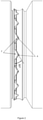
- FIG. 1 there is shown a joint assembly according to the present invention.
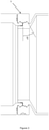
- FIG. 2 there is shown an enlarged view of this assembly from which the interaction between the teeth of the respective flanges can be derived.
- the following description serves to enable a skilled person to work the invention.
- the present invention is particularly suitable for quickly establishing a rigid and ruggedized robot joint between two flanges. Specifically this is achieved by a first annular flange (1) with a first contact surface provided with evenly distributed teeth (2) along the circumference of the flange, and which flange (1) may be secured to a second annular flange (3) with a second contact surface provided with evenly distributed cavities (4) for receiving the teeth (3) along the circumference of that flange (3).
- V-clamp couplings can be easily assembled and disassembled, they are often used on equipment that requires frequent service or maintenance.
- a higher number of teeth will generally raise the connections ability to transfer high loads.
- the angle of the teeth can be used to control the relationship between the connections strength for moment forces around the center axis and bending forces.
- the angle of the V-clamps can be adapted to the application. In general a flatter angle raises the load carrying ability, but requires a stronger clamp, and vice versa.
- the angle of both the teeth and the V-clamps are 30° from horizontal which represents a good design for most applications.
- the preferred design of the V-clamps is 2 halves each covering 180° perimeter of the flanges. These 2 clamps are held together by 2 screws (6).
- Another possibility is to connect 2 or more clamps into a chain with pins or other method, so that only 1 screw is necessary to tighten the clamps around the connection.
- Yet another possibility is to use an eccentric tightening principle with a permanent handle so the connection can be made without using tools. This system is known from V-clamps in pipe systems that can be quickly coupled.
Landscapes
- Engineering & Computer Science (AREA)
- Robotics (AREA)
- Mechanical Engineering (AREA)
- Manipulator (AREA)
Claims (10)
- Ensemble de joint de robot libérable pour établir une articulation comprenant :- un premier composant ayant une première bride annulaire (1) avec une première surface de contact prévue au niveau d'un plan formé par ladite première bride annulaire, une surface circonférentielle extérieure de ladite première bride annulaire étant inclinée par rapport audit plan formé par ladite première bride annulaire ;- un second composant ayant une seconde bride annulaire (3) avec une seconde surface de contact prévue au niveau d'un plan formé par ladite seconde bride annulaire, une surface circonférentielle extérieure de ladite seconde bride annulaire étant inclinée par rapport audit plan formé par ladite seconde bride annulaire ;- une pince (5) pour maintenir les premier et second composants en place, ladite pince étant une pince en V comprenant des surfaces de contact intérieures configurées pour venir en prise avec les surfaces circonférentielles extérieures de ladite première bride annulaire et de ladite seconde bride annulaire, les surfaces de contact intérieures étant inclinées entre le plan divisant les deux brides et la surface de contact maintenant les brides respectives en place ;caractérisé en ce que- ladite première surface de contact comprend des dents (2) faisant saillie à partir dudit plan formé par ladite première bride annulaire (1) et lesdites dents sont réparties le long de la circonférence de ladite première bride annulaire ;- ladite seconde surface de contact comprend des cavités (4) pour recevoir lesdites dents, où lesdites cavités sont formées dans ladite seconde surface de contact et distribuées le long de la circonférence de ladite seconde bride annulaire ;l'angle des faces de contact desdites dents ayant le même angle que les faces de contact desdites cavités, de sorte que ladite pince maintient ensemble lesdits premier et second composants.
- Ensemble de joint de robot libérable selon la revendication 1, les sommets desdites dents ne touchant pas les fonds desdites cavités.
- Ensemble de joint de robot libérable selon la revendication 1 ou 2, la pince maintenant les premier et second composants pour former un joint non compressible.
- Ensemble de joint de robot libérable selon l'une quelconque des revendications 1 à 3, les premier et second composants étant constitués de métaux ou d'alliages de métaux.
- Ensemble de joint de robot libérable selon l'une quelconque des revendications 1 à 4, les premier et second composants étant constitués de matériaux différents avec une dureté différente.
- Ensemble de joint de robot libérable selon l'une quelconque des revendications 1 à 3 ou 5, le premier et/ou le second composant étant constitués d'un matériau polymère, tel que la fibre de verre, la fibre de carbone, le polycarbonate, le nylon ou le polystyrène.
- Ensemble de joint de robot libérable selon l'une quelconque des revendications précédentes, l'angle des faces de contact étant de 15-75 degrés, de préférence de 20-45 degrés.
- Ensemble de joint de robot libérable selon l'une quelconque des revendications précédentes, l'une des dents étant plus large ou plus étroite que les dents restantes ou l'une des dents ayant une distance ou une hauteur non uniforme entre les dents pour assurer une connexion correcte entre les composants.
- Robot modulaire comprenant l'ensemble de joint de robot libérable selon l'une quelconque des revendications 1 à 8.
- Bras robotique comprenant l'ensemble de joint de robot libérable selon l'une quelconque des revendications 1 à 8.
Priority Applications (7)
| Application Number | Priority Date | Filing Date | Title |
|---|---|---|---|
| ES17151442T ES2914624T3 (es) | 2017-01-13 | 2017-01-13 | Junta con rebordes embridados |
| DK17151442.5T DK3348361T3 (da) | 2017-01-13 | 2017-01-13 | Fastspændt flangesamling |
| EP17151442.5A EP3348361B1 (fr) | 2017-01-13 | 2017-01-13 | Joint de bride à serrage |
| TW106145070A TWI765946B (zh) | 2017-01-13 | 2017-12-21 | 夾合凸緣關節及相關模組化機器人 |
| US16/473,018 US11260543B2 (en) | 2017-01-13 | 2018-01-03 | Clamped flange joint |
| CN201880006424.5A CN110167725B (zh) | 2017-01-13 | 2018-01-03 | 夹具式凸缘接头 |
| PCT/EP2018/050144 WO2018130447A1 (fr) | 2017-01-13 | 2018-01-03 | Raccord à brides serrées |
Applications Claiming Priority (1)
| Application Number | Priority Date | Filing Date | Title |
|---|---|---|---|
| EP17151442.5A EP3348361B1 (fr) | 2017-01-13 | 2017-01-13 | Joint de bride à serrage |
Publications (2)
| Publication Number | Publication Date |
|---|---|
| EP3348361A1 EP3348361A1 (fr) | 2018-07-18 |
| EP3348361B1 true EP3348361B1 (fr) | 2022-03-09 |
Family
ID=57799604
Family Applications (1)
| Application Number | Title | Priority Date | Filing Date |
|---|---|---|---|
| EP17151442.5A Active EP3348361B1 (fr) | 2017-01-13 | 2017-01-13 | Joint de bride à serrage |
Country Status (7)
| Country | Link |
|---|---|
| US (1) | US11260543B2 (fr) |
| EP (1) | EP3348361B1 (fr) |
| CN (1) | CN110167725B (fr) |
| DK (1) | DK3348361T3 (fr) |
| ES (1) | ES2914624T3 (fr) |
| TW (1) | TWI765946B (fr) |
| WO (1) | WO2018130447A1 (fr) |
Families Citing this family (32)
| Publication number | Priority date | Publication date | Assignee | Title |
|---|---|---|---|---|
| CA2906772C (fr) * | 2013-03-15 | 2021-09-21 | Board Of Regents Of The University Of Nebraska | Dispositifs chirurgicaux robotiques, systemes et procedes apparentes |
| KR102471820B1 (ko) | 2017-11-15 | 2022-11-29 | 유니버셜 로보츠 에이/에스 | 스트레인 웨이브 기어 |
| EP3793787B1 (fr) | 2018-05-18 | 2023-11-15 | Universal Robots A/S | Articulation de robot comprenant un ensemble de frein |
| US11839979B2 (en) | 2018-06-15 | 2023-12-12 | Universal Robots A/S | Dual mode free-drive of robot arm |
| EP3623113A1 (fr) | 2018-09-14 | 2020-03-18 | Universal Robots A/S | Obtention de la rigidité d'engrenage d'une roue d'articulation de robot d'un bras de robot |
| US11218054B2 (en) | 2019-03-28 | 2022-01-04 | Nidec Motor Corporation | Motor with rotation sensor |
| US12661791B2 (en) | 2019-04-02 | 2026-06-23 | Universal Robots A/S | Robot arm safety system with runtime adaptable safety limits |
| CN113891786B (zh) | 2019-04-17 | 2024-07-12 | 优傲机器人公司 | 基于自适应摩擦来控制机器人臂的方法 |
| CN113874174B (zh) | 2019-05-29 | 2025-03-11 | 优傲机器人公司 | 在机器人臂与对象之间的接触的变化的检测 |
| CN110561487A (zh) * | 2019-09-07 | 2019-12-13 | 埃夫特智能装备股份有限公司 | 一种用于机器人关节的正反螺纹快速连接机构 |
| US12384019B2 (en) | 2019-10-22 | 2025-08-12 | Universal Robots A/S | Safe activation of free-drive mode of robot arm |
| CN114599489B (zh) | 2019-10-22 | 2026-04-10 | 优傲机器人公司 | 处于自动驱动的具有自适应三维边界的机器人臂 |
| DK180508B1 (en) | 2019-10-22 | 2021-06-03 | Universal Robots As | Maintaining free-drive mode of robot arm for period of time |
| US11548171B2 (en) * | 2019-10-30 | 2023-01-10 | Industrial Technology Research Institute | Robot arm, mechanical assembly and assembly method thereof |
| CN211761651U (zh) * | 2019-11-13 | 2020-10-27 | 富士能电子(昆山)有限公司 | 多轴机械手臂 |
| DK180673B1 (en) | 2019-12-29 | 2021-11-25 | Universal Robots As | Method of obtaining vibrational properties of robot arm |
| EP4149730A1 (fr) | 2020-05-14 | 2023-03-22 | Universal Robots A/S | Commande de mise en forme d'entrée d'un bras de robot dans différents espaces de référence |
| CN116194852A (zh) | 2020-10-09 | 2023-05-30 | 优傲机器人公司 | 用于机器人臂的多功能输入设备 |
| CN116472145B (zh) | 2020-11-06 | 2026-02-03 | 优傲机器人公司 | 机器人系统和用于监测机器人系统的方法 |
| CN112549069B (zh) * | 2020-12-08 | 2022-03-01 | 广东博智林机器人有限公司 | 机械臂关节结构及机械臂 |
| DK180930B1 (en) | 2021-03-25 | 2022-06-29 | Universal Robots As | Strain wave gear with encoder integration |
| EP4384359A1 (fr) | 2021-08-13 | 2024-06-19 | Universal Robots A/S | Système robotisé destiné à la détection d'anomalie |
| USD1099187S1 (en) | 2022-01-14 | 2025-10-21 | Universal Robots A/S | Robot joint |
| USD1082878S1 (en) | 2022-01-14 | 2025-07-08 | Universal Robots A/S | Robot joint |
| CN116766253A (zh) * | 2022-03-11 | 2023-09-19 | 美的集团(上海)有限公司 | 快拆机构、机身及机器人 |
| CN114932574A (zh) * | 2022-04-11 | 2022-08-23 | 深圳市大族机器人有限公司 | 关节组件及机械臂 |
| WO2023246994A1 (fr) | 2022-06-20 | 2023-12-28 | Universal Robots A/S | Élément de robot doté d'une bague d'éclairage |
| DE102022134703B3 (de) * | 2022-12-23 | 2024-05-02 | Kuka Deutschland Gmbh | Verbindungsvorrichtung mit mehreren auf einem Umfang angeordneten Eingriffselementen und Roboterarm |
| USD1054942S1 (en) * | 2023-07-05 | 2024-12-24 | Shanghai Baidun Auto Parts Co., Ltd | Exhaust reducer assembly |
| WO2025186396A1 (fr) * | 2024-03-08 | 2025-09-12 | Kassow Robots Aps | Assemblage de composants amélioré pour système robotique |
| DE102024112446B3 (de) * | 2024-05-03 | 2025-06-18 | Neura Robotics GmbH | Flanschverbindung mit mindestens einem Klemmkörper sowie Roboterarm |
| EP4786113A1 (fr) | 2025-02-03 | 2026-08-05 | RobCo GmbH | Dispositif d'accouplement pour un robot modulaire, unité d'accouplement, module pour un robot modulaire, robot modulaire et procédé d'assemblage au moins partiel d'un robot modulaire |
Family Cites Families (22)
| Publication number | Priority date | Publication date | Assignee | Title |
|---|---|---|---|---|
| US2092704A (en) * | 1936-05-21 | 1937-09-07 | Ricefield Louis | Coupling |
| US2195492A (en) * | 1938-06-21 | 1940-04-02 | Frank A Mcdonald | Quick coupling |
| US2303032A (en) * | 1941-07-31 | 1942-11-24 | Century Motors Corp | Coupling |
| US2303031A (en) * | 1941-07-31 | 1942-11-24 | Century Motors Corp | Coupling |
| US3744577A (en) * | 1971-10-01 | 1973-07-10 | Dresser Ind | Earth boring machine with a readily replaceable drill rod chuck |
| DE2554574A1 (de) * | 1975-12-04 | 1977-06-08 | Gelenkwellenbau Gmbh | Scheibenkupplung zum anschluss von wellen |
| DE3149156A1 (de) * | 1981-12-11 | 1983-06-23 | J.M. Voith Gmbh, 7920 Heidenheim | Kupplung zum starren verbinden koaxialer bauteile und deren verwendung bei gelenkwellen |
| US4821818A (en) * | 1988-02-01 | 1989-04-18 | Micro Specialties Co., Inc. | Tube auger sections |
| DE3825993C1 (fr) * | 1988-07-28 | 1989-12-21 | Mannesmann Ag, 4000 Duesseldorf, De | |
| US5269572A (en) * | 1992-08-28 | 1993-12-14 | Gold Star Manufacturing, Inc. | Apparatus and method for coupling elongated members |
| GB9713765D0 (en) | 1997-07-01 | 1997-09-03 | Engineering Services Inc | Reconfigurable mudular drive system |
| ITMI20021352A1 (it) * | 2002-06-19 | 2003-12-19 | Asterika Ltd | Dispositivo di connessione tra organi di una macchina |
| US8079773B2 (en) * | 2005-10-18 | 2011-12-20 | General Electric Company | Methods and apparatus for assembling composite structures |
| EP1792818A1 (fr) * | 2005-12-02 | 2007-06-06 | Campagnolo S.R.L. | Axe et manivelle de pédalier de bicyclette, dispositif de pédalier comprenant un tel axe et pédalier de bicyclette et procède pour assembler le pédalier de bicyclette |
| PL1996376T3 (pl) | 2006-03-03 | 2016-12-30 | Programowalny robot i interfejs użytkownika | |
| EP1932630A1 (fr) * | 2006-12-11 | 2008-06-18 | Abb As | Poignet d'un robot industriel |
| US9144909B2 (en) * | 2007-07-05 | 2015-09-29 | Re2, Inc. | Defense related robotic systems |
| EP2441594B1 (fr) * | 2007-10-03 | 2013-04-24 | JTEKT Corporation | Appareil de support de roue |
| GB2489135B (en) * | 2010-01-20 | 2013-10-09 | Faro Tech Inc | Display for coordinate measuring machine |
| EP2453325A1 (fr) | 2010-11-16 | 2012-05-16 | Universal Robots ApS | Procédé et support de commande d'un robot |
| WO2013045314A1 (fr) | 2011-09-28 | 2013-04-04 | Universal Robots A/S | Étalonnage et programmation de robots |
| US9505136B1 (en) * | 2013-06-24 | 2016-11-29 | Redwood Robotics | Precision assembly of robotic components |
-
2017
- 2017-01-13 EP EP17151442.5A patent/EP3348361B1/fr active Active
- 2017-01-13 ES ES17151442T patent/ES2914624T3/es active Active
- 2017-01-13 DK DK17151442.5T patent/DK3348361T3/da active
- 2017-12-21 TW TW106145070A patent/TWI765946B/zh active
-
2018
- 2018-01-03 US US16/473,018 patent/US11260543B2/en active Active
- 2018-01-03 CN CN201880006424.5A patent/CN110167725B/zh active Active
- 2018-01-03 WO PCT/EP2018/050144 patent/WO2018130447A1/fr not_active Ceased
Also Published As
| Publication number | Publication date |
|---|---|
| US11260543B2 (en) | 2022-03-01 |
| WO2018130447A1 (fr) | 2018-07-19 |
| TWI765946B (zh) | 2022-06-01 |
| CN110167725B (zh) | 2022-12-20 |
| TW201825249A (zh) | 2018-07-16 |
| US20200391393A1 (en) | 2020-12-17 |
| ES2914624T3 (es) | 2022-06-14 |
| DK3348361T3 (da) | 2022-03-21 |
| CN110167725A (zh) | 2019-08-23 |
| EP3348361A1 (fr) | 2018-07-18 |
Similar Documents
| Publication | Publication Date | Title |
|---|---|---|
| US11260543B2 (en) | Clamped flange joint | |
| CA2592905C (fr) | Systeme a effecteur geometrique | |
| US12202127B2 (en) | Adjustable suction gripper | |
| EP3983181B1 (fr) | Changeur d'outil pour robots collaboratifs, système de changeur d'outil de robot et procédé pour relier un outil à un bras de robot | |
| US6491612B1 (en) | Stud welding tool changer | |
| JP5883037B2 (ja) | 回転及び直線方向の調整のためのギザギザの歯を有するモジュラ工具装置 | |
| US9321180B2 (en) | Industrial robot device, an industrial robot and a method for manipulating objects | |
| CN114174004A (zh) | 臂模块、机器人臂和工业机器人 | |
| US20060285915A1 (en) | Apparatus for incrementally adjusting a modular tooling coupling | |
| US10994425B1 (en) | Collaborative robot hand bearing for high-torque tightening applications | |
| CN117943824A (zh) | 螺丝操作机器人 | |
| CN120418046A (zh) | 连接装置和机器人臂 | |
| CN203903786U (zh) | 一种多自由度平移翻转机械手 | |
| CN118789478A (zh) | 快速可靠的弯头夹持定位模块 | |
| CN212558359U (zh) | 一种机械臂取放料夹爪 | |
| TWM555789U (zh) | 機械手視覺夾爪環型快拆模組 | |
| CN223186534U (zh) | 一种夹持装置及机械臂 | |
| CN207309970U (zh) | 一种方便更换夹具的机器人手臂 | |
| CN218016800U (zh) | 焊接辅助装置 | |
| CN212821958U (zh) | 弯管工具 | |
| TWM607799U (zh) | 關節裝置 | |
| CN215058175U (zh) | 一种流化风机轴封安装装置 | |
| RU189796U1 (ru) | Быстроразъемное соединительное устройство для конического фланцевого соединения | |
| CN121870506A (zh) | 一种三通法兰夹紧机构 | |
| CN211053740U (zh) | 机器人法兰角度转换器 |
Legal Events
| Date | Code | Title | Description |
|---|---|---|---|
| PUAI | Public reference made under article 153(3) epc to a published international application that has entered the european phase |
Free format text: ORIGINAL CODE: 0009012 |
|
| STAA | Information on the status of an ep patent application or granted ep patent |
Free format text: STATUS: THE APPLICATION HAS BEEN PUBLISHED |
|
| AK | Designated contracting states |
Kind code of ref document: A1 Designated state(s): AL AT BE BG CH CY CZ DE DK EE ES FI FR GB GR HR HU IE IS IT LI LT LU LV MC MK MT NL NO PL PT RO RS SE SI SK SM TR |
|
| AX | Request for extension of the european patent |
Extension state: BA ME |
|
| STAA | Information on the status of an ep patent application or granted ep patent |
Free format text: STATUS: REQUEST FOR EXAMINATION WAS MADE |
|
| 17P | Request for examination filed |
Effective date: 20190109 |
|
| RBV | Designated contracting states (corrected) |
Designated state(s): AL AT BE BG CH CY CZ DE DK EE ES FI FR GB GR HR HU IE IS IT LI LT LU LV MC MK MT NL NO PL PT RO RS SE SI SK SM TR |
|
| STAA | Information on the status of an ep patent application or granted ep patent |
Free format text: STATUS: EXAMINATION IS IN PROGRESS |
|
| 17Q | First examination report despatched |
Effective date: 20210504 |
|
| RIC1 | Information provided on ipc code assigned before grant |
Ipc: B23Q 1/00 20060101ALN20210922BHEP Ipc: B25J 15/04 20060101ALI20210922BHEP Ipc: B25J 17/00 20060101AFI20210922BHEP |
|
| GRAP | Despatch of communication of intention to grant a patent |
Free format text: ORIGINAL CODE: EPIDOSNIGR1 |
|
| STAA | Information on the status of an ep patent application or granted ep patent |
Free format text: STATUS: GRANT OF PATENT IS INTENDED |
|
| INTG | Intention to grant announced |
Effective date: 20211126 |
|
| RAP3 | Party data changed (applicant data changed or rights of an application transferred) |
Owner name: UNIVERSAL ROBOTS A/S |
|
| GRAS | Grant fee paid |
Free format text: ORIGINAL CODE: EPIDOSNIGR3 |
|
| GRAA | (expected) grant |
Free format text: ORIGINAL CODE: 0009210 |
|
| STAA | Information on the status of an ep patent application or granted ep patent |
Free format text: STATUS: THE PATENT HAS BEEN GRANTED |
|
| AK | Designated contracting states |
Kind code of ref document: B1 Designated state(s): AL AT BE BG CH CY CZ DE DK EE ES FI FR GB GR HR HU IE IS IT LI LT LU LV MC MK MT NL NO PL PT RO RS SE SI SK SM TR |
|
| REG | Reference to a national code |
Ref country code: CH Ref legal event code: EP Ref country code: AT Ref legal event code: REF Ref document number: 1473730 Country of ref document: AT Kind code of ref document: T Effective date: 20220315 |
|
| REG | Reference to a national code |
Ref country code: DK Ref legal event code: T3 Effective date: 20220315 |
|
| REG | Reference to a national code |
Ref country code: DE Ref legal event code: R096 Ref document number: 602017054263 Country of ref document: DE |
|
| REG | Reference to a national code |
Ref country code: IE Ref legal event code: FG4D |
|
| REG | Reference to a national code |
Ref country code: SE Ref legal event code: TRGR Ref country code: ES Ref legal event code: FG2A Ref document number: 2914624 Country of ref document: ES Kind code of ref document: T3 Effective date: 20220614 |
|
| REG | Reference to a national code |
Ref country code: LT Ref legal event code: MG9D |
|
| REG | Reference to a national code |
Ref country code: NL Ref legal event code: MP Effective date: 20220309 |
|
| PG25 | Lapsed in a contracting state [announced via postgrant information from national office to epo] |
Ref country code: RS Free format text: LAPSE BECAUSE OF FAILURE TO SUBMIT A TRANSLATION OF THE DESCRIPTION OR TO PAY THE FEE WITHIN THE PRESCRIBED TIME-LIMIT Effective date: 20220309 Ref country code: NO Free format text: LAPSE BECAUSE OF FAILURE TO SUBMIT A TRANSLATION OF THE DESCRIPTION OR TO PAY THE FEE WITHIN THE PRESCRIBED TIME-LIMIT Effective date: 20220609 Ref country code: LT Free format text: LAPSE BECAUSE OF FAILURE TO SUBMIT A TRANSLATION OF THE DESCRIPTION OR TO PAY THE FEE WITHIN THE PRESCRIBED TIME-LIMIT Effective date: 20220309 Ref country code: HR Free format text: LAPSE BECAUSE OF FAILURE TO SUBMIT A TRANSLATION OF THE DESCRIPTION OR TO PAY THE FEE WITHIN THE PRESCRIBED TIME-LIMIT Effective date: 20220309 Ref country code: BG Free format text: LAPSE BECAUSE OF FAILURE TO SUBMIT A TRANSLATION OF THE DESCRIPTION OR TO PAY THE FEE WITHIN THE PRESCRIBED TIME-LIMIT Effective date: 20220609 |
|
| REG | Reference to a national code |
Ref country code: AT Ref legal event code: MK05 Ref document number: 1473730 Country of ref document: AT Kind code of ref document: T Effective date: 20220309 |
|
| PG25 | Lapsed in a contracting state [announced via postgrant information from national office to epo] |
Ref country code: LV Free format text: LAPSE BECAUSE OF FAILURE TO SUBMIT A TRANSLATION OF THE DESCRIPTION OR TO PAY THE FEE WITHIN THE PRESCRIBED TIME-LIMIT Effective date: 20220309 Ref country code: GR Free format text: LAPSE BECAUSE OF FAILURE TO SUBMIT A TRANSLATION OF THE DESCRIPTION OR TO PAY THE FEE WITHIN THE PRESCRIBED TIME-LIMIT Effective date: 20220610 Ref country code: FI Free format text: LAPSE BECAUSE OF FAILURE TO SUBMIT A TRANSLATION OF THE DESCRIPTION OR TO PAY THE FEE WITHIN THE PRESCRIBED TIME-LIMIT Effective date: 20220309 |
|
| PG25 | Lapsed in a contracting state [announced via postgrant information from national office to epo] |
Ref country code: NL Free format text: LAPSE BECAUSE OF FAILURE TO SUBMIT A TRANSLATION OF THE DESCRIPTION OR TO PAY THE FEE WITHIN THE PRESCRIBED TIME-LIMIT Effective date: 20220309 |
|
| PG25 | Lapsed in a contracting state [announced via postgrant information from national office to epo] |
Ref country code: SM Free format text: LAPSE BECAUSE OF FAILURE TO SUBMIT A TRANSLATION OF THE DESCRIPTION OR TO PAY THE FEE WITHIN THE PRESCRIBED TIME-LIMIT Effective date: 20220309 Ref country code: SK Free format text: LAPSE BECAUSE OF FAILURE TO SUBMIT A TRANSLATION OF THE DESCRIPTION OR TO PAY THE FEE WITHIN THE PRESCRIBED TIME-LIMIT Effective date: 20220309 Ref country code: RO Free format text: LAPSE BECAUSE OF FAILURE TO SUBMIT A TRANSLATION OF THE DESCRIPTION OR TO PAY THE FEE WITHIN THE PRESCRIBED TIME-LIMIT Effective date: 20220309 Ref country code: PT Free format text: LAPSE BECAUSE OF FAILURE TO SUBMIT A TRANSLATION OF THE DESCRIPTION OR TO PAY THE FEE WITHIN THE PRESCRIBED TIME-LIMIT Effective date: 20220711 Ref country code: EE Free format text: LAPSE BECAUSE OF FAILURE TO SUBMIT A TRANSLATION OF THE DESCRIPTION OR TO PAY THE FEE WITHIN THE PRESCRIBED TIME-LIMIT Effective date: 20220309 Ref country code: CZ Free format text: LAPSE BECAUSE OF FAILURE TO SUBMIT A TRANSLATION OF THE DESCRIPTION OR TO PAY THE FEE WITHIN THE PRESCRIBED TIME-LIMIT Effective date: 20220309 Ref country code: AT Free format text: LAPSE BECAUSE OF FAILURE TO SUBMIT A TRANSLATION OF THE DESCRIPTION OR TO PAY THE FEE WITHIN THE PRESCRIBED TIME-LIMIT Effective date: 20220309 |
|
| PG25 | Lapsed in a contracting state [announced via postgrant information from national office to epo] |
Ref country code: PL Free format text: LAPSE BECAUSE OF FAILURE TO SUBMIT A TRANSLATION OF THE DESCRIPTION OR TO PAY THE FEE WITHIN THE PRESCRIBED TIME-LIMIT Effective date: 20220309 Ref country code: IS Free format text: LAPSE BECAUSE OF FAILURE TO SUBMIT A TRANSLATION OF THE DESCRIPTION OR TO PAY THE FEE WITHIN THE PRESCRIBED TIME-LIMIT Effective date: 20220709 Ref country code: AL Free format text: LAPSE BECAUSE OF FAILURE TO SUBMIT A TRANSLATION OF THE DESCRIPTION OR TO PAY THE FEE WITHIN THE PRESCRIBED TIME-LIMIT Effective date: 20220309 |
|
| REG | Reference to a national code |
Ref country code: DE Ref legal event code: R097 Ref document number: 602017054263 Country of ref document: DE |
|
| PLBE | No opposition filed within time limit |
Free format text: ORIGINAL CODE: 0009261 |
|
| STAA | Information on the status of an ep patent application or granted ep patent |
Free format text: STATUS: NO OPPOSITION FILED WITHIN TIME LIMIT |
|
| 26N | No opposition filed |
Effective date: 20221212 |
|
| PG25 | Lapsed in a contracting state [announced via postgrant information from national office to epo] |
Ref country code: SI Free format text: LAPSE BECAUSE OF FAILURE TO SUBMIT A TRANSLATION OF THE DESCRIPTION OR TO PAY THE FEE WITHIN THE PRESCRIBED TIME-LIMIT Effective date: 20220309 |
|
| P01 | Opt-out of the competence of the unified patent court (upc) registered |
Effective date: 20230412 |
|
| PG25 | Lapsed in a contracting state [announced via postgrant information from national office to epo] |
Ref country code: LU Free format text: LAPSE BECAUSE OF NON-PAYMENT OF DUE FEES Effective date: 20230113 |
|
| REG | Reference to a national code |
Ref country code: BE Ref legal event code: MM Effective date: 20230131 |
|
| PG25 | Lapsed in a contracting state [announced via postgrant information from national office to epo] |
Ref country code: BE Free format text: LAPSE BECAUSE OF NON-PAYMENT OF DUE FEES Effective date: 20230131 |
|
| PG25 | Lapsed in a contracting state [announced via postgrant information from national office to epo] |
Ref country code: IE Free format text: LAPSE BECAUSE OF NON-PAYMENT OF DUE FEES Effective date: 20230113 |
|
| PG25 | Lapsed in a contracting state [announced via postgrant information from national office to epo] |
Ref country code: MC Free format text: LAPSE BECAUSE OF FAILURE TO SUBMIT A TRANSLATION OF THE DESCRIPTION OR TO PAY THE FEE WITHIN THE PRESCRIBED TIME-LIMIT Effective date: 20220309 |
|
| PG25 | Lapsed in a contracting state [announced via postgrant information from national office to epo] |
Ref country code: MC Free format text: LAPSE BECAUSE OF FAILURE TO SUBMIT A TRANSLATION OF THE DESCRIPTION OR TO PAY THE FEE WITHIN THE PRESCRIBED TIME-LIMIT Effective date: 20220309 |
|
| REG | Reference to a national code |
Ref country code: DE Ref legal event code: R083 Ref document number: 602017054263 Country of ref document: DE |
|
| PG25 | Lapsed in a contracting state [announced via postgrant information from national office to epo] |
Ref country code: CY Free format text: LAPSE BECAUSE OF FAILURE TO SUBMIT A TRANSLATION OF THE DESCRIPTION OR TO PAY THE FEE WITHIN THE PRESCRIBED TIME-LIMIT; INVALID AB INITIO Effective date: 20170113 |
|
| PG25 | Lapsed in a contracting state [announced via postgrant information from national office to epo] |
Ref country code: HU Free format text: LAPSE BECAUSE OF FAILURE TO SUBMIT A TRANSLATION OF THE DESCRIPTION OR TO PAY THE FEE WITHIN THE PRESCRIBED TIME-LIMIT; INVALID AB INITIO Effective date: 20170113 |
|
| PG25 | Lapsed in a contracting state [announced via postgrant information from national office to epo] |
Ref country code: TR Free format text: LAPSE BECAUSE OF FAILURE TO SUBMIT A TRANSLATION OF THE DESCRIPTION OR TO PAY THE FEE WITHIN THE PRESCRIBED TIME-LIMIT Effective date: 20220309 |
|
| PGFP | Annual fee paid to national office [announced via postgrant information from national office to epo] |
Ref country code: GB Payment date: 20251204 Year of fee payment: 10 |
|
| PGFP | Annual fee paid to national office [announced via postgrant information from national office to epo] |
Ref country code: FR Payment date: 20251208 Year of fee payment: 10 |
|
| PGFP | Annual fee paid to national office [announced via postgrant information from national office to epo] |
Ref country code: SE Payment date: 20251210 Year of fee payment: 10 |
|
| REG | Reference to a national code |
Ref country code: CH Ref legal event code: U11 Free format text: ST27 STATUS EVENT CODE: U-0-0-U10-U11 (AS PROVIDED BY THE NATIONAL OFFICE) Effective date: 20260201 |
|
| PGFP | Annual fee paid to national office [announced via postgrant information from national office to epo] |
Ref country code: ES Payment date: 20260213 Year of fee payment: 10 |
|
| PGFP | Annual fee paid to national office [announced via postgrant information from national office to epo] |
Ref country code: DE Payment date: 20251203 Year of fee payment: 10 Ref country code: DK Payment date: 20260113 Year of fee payment: 10 |
|
| PGFP | Annual fee paid to national office [announced via postgrant information from national office to epo] |
Ref country code: IT Payment date: 20251219 Year of fee payment: 10 |
|
| PGFP | Annual fee paid to national office [announced via postgrant information from national office to epo] |
Ref country code: CH Payment date: 20260201 Year of fee payment: 10 |