EP3348383B1 - Verfahren und vorrichtung zum applizieren einer komponente an einem bauteil mittels eines manipulators - Google Patents
Verfahren und vorrichtung zum applizieren einer komponente an einem bauteil mittels eines manipulators Download PDFInfo
- Publication number
- EP3348383B1 EP3348383B1 EP17206429.7A EP17206429A EP3348383B1 EP 3348383 B1 EP3348383 B1 EP 3348383B1 EP 17206429 A EP17206429 A EP 17206429A EP 3348383 B1 EP3348383 B1 EP 3348383B1
- Authority
- EP
- European Patent Office
- Prior art keywords
- component
- support element
- assembly
- membrane
- manipulator
- Prior art date
- Legal status (The legal status is an assumption and is not a legal conclusion. Google has not performed a legal analysis and makes no representation as to the accuracy of the status listed.)
- Active
Links
Images


Classifications
-
- B—PERFORMING OPERATIONS; TRANSPORTING
- B29—WORKING OF PLASTICS; WORKING OF SUBSTANCES IN A PLASTIC STATE IN GENERAL
- B29C—SHAPING OR JOINING OF PLASTICS; SHAPING OF MATERIAL IN A PLASTIC STATE, NOT OTHERWISE PROVIDED FOR; AFTER-TREATMENT OF THE SHAPED PRODUCTS, e.g. REPAIRING
- B29C65/00—Joining or sealing of preformed parts, e.g. welding of plastics materials; Apparatus therefor
- B29C65/78—Means for handling the parts to be joined, e.g. for making containers or hollow articles, e.g. means for handling sheets, plates, web-like materials, tubular articles, hollow articles or elements to be joined therewith; Means for discharging the joined articles from the joining apparatus
- B29C65/7841—Holding or clamping means for handling purposes
- B29C65/7847—Holding or clamping means for handling purposes using vacuum to hold at least one of the parts to be joined
-
- B—PERFORMING OPERATIONS; TRANSPORTING
- B29—WORKING OF PLASTICS; WORKING OF SUBSTANCES IN A PLASTIC STATE IN GENERAL
- B29C—SHAPING OR JOINING OF PLASTICS; SHAPING OF MATERIAL IN A PLASTIC STATE, NOT OTHERWISE PROVIDED FOR; AFTER-TREATMENT OF THE SHAPED PRODUCTS, e.g. REPAIRING
- B29C66/00—General aspects of processes or apparatus for joining preformed parts
- B29C66/50—General aspects of joining tubular articles; General aspects of joining long products, i.e. bars or profiled elements; General aspects of joining single elements to tubular articles, hollow articles or bars; General aspects of joining several hollow-preforms to form hollow or tubular articles
- B29C66/51—Joining tubular articles, profiled elements or bars; Joining single elements to tubular articles, hollow articles or bars; Joining several hollow-preforms to form hollow or tubular articles
- B29C66/53—Joining single elements to tubular articles, hollow articles or bars
- B29C66/532—Joining single elements to the wall of tubular articles, hollow articles or bars
- B29C66/5326—Joining single elements to the wall of tubular articles, hollow articles or bars said single elements being substantially flat
-
- B—PERFORMING OPERATIONS; TRANSPORTING
- B29—WORKING OF PLASTICS; WORKING OF SUBSTANCES IN A PLASTIC STATE IN GENERAL
- B29C—SHAPING OR JOINING OF PLASTICS; SHAPING OF MATERIAL IN A PLASTIC STATE, NOT OTHERWISE PROVIDED FOR; AFTER-TREATMENT OF THE SHAPED PRODUCTS, e.g. REPAIRING
- B29C66/00—General aspects of processes or apparatus for joining preformed parts
- B29C66/70—General aspects of processes or apparatus for joining preformed parts characterised by the composition, physical properties or the structure of the material of the parts to be joined; Joining with non-plastics material
- B29C66/72—General aspects of processes or apparatus for joining preformed parts characterised by the composition, physical properties or the structure of the material of the parts to be joined; Joining with non-plastics material characterised by the structure of the material of the parts to be joined
- B29C66/723—General aspects of processes or apparatus for joining preformed parts characterised by the composition, physical properties or the structure of the material of the parts to be joined; Joining with non-plastics material characterised by the structure of the material of the parts to be joined being multi-layered
- B29C66/7232—General aspects of processes or apparatus for joining preformed parts characterised by the composition, physical properties or the structure of the material of the parts to be joined; Joining with non-plastics material characterised by the structure of the material of the parts to be joined being multi-layered comprising a non-plastics layer
- B29C66/72321—General aspects of processes or apparatus for joining preformed parts characterised by the composition, physical properties or the structure of the material of the parts to be joined; Joining with non-plastics material characterised by the structure of the material of the parts to be joined being multi-layered comprising a non-plastics layer consisting of metals or their alloys
-
- B—PERFORMING OPERATIONS; TRANSPORTING
- B29—WORKING OF PLASTICS; WORKING OF SUBSTANCES IN A PLASTIC STATE IN GENERAL
- B29C—SHAPING OR JOINING OF PLASTICS; SHAPING OF MATERIAL IN A PLASTIC STATE, NOT OTHERWISE PROVIDED FOR; AFTER-TREATMENT OF THE SHAPED PRODUCTS, e.g. REPAIRING
- B29C66/00—General aspects of processes or apparatus for joining preformed parts
- B29C66/80—General aspects of machine operations or constructions and parts thereof
- B29C66/81—General aspects of the pressing elements, i.e. the elements applying pressure on the parts to be joined in the area to be joined, e.g. the welding jaws or clamps
- B29C66/814—General aspects of the pressing elements, i.e. the elements applying pressure on the parts to be joined in the area to be joined, e.g. the welding jaws or clamps characterised by the design of the pressing elements, e.g. of the welding jaws or clamps
- B29C66/8145—General aspects of the pressing elements, i.e. the elements applying pressure on the parts to be joined in the area to be joined, e.g. the welding jaws or clamps characterised by the design of the pressing elements, e.g. of the welding jaws or clamps characterised by the constructional aspects of the pressing elements, e.g. of the welding jaws or clamps
- B29C66/81455—General aspects of the pressing elements, i.e. the elements applying pressure on the parts to be joined in the area to be joined, e.g. the welding jaws or clamps characterised by the design of the pressing elements, e.g. of the welding jaws or clamps characterised by the constructional aspects of the pressing elements, e.g. of the welding jaws or clamps being a fluid inflatable bag or bladder, a diaphragm or a vacuum bag for applying isostatic pressure
-
- B—PERFORMING OPERATIONS; TRANSPORTING
- B29—WORKING OF PLASTICS; WORKING OF SUBSTANCES IN A PLASTIC STATE IN GENERAL
- B29C—SHAPING OR JOINING OF PLASTICS; SHAPING OF MATERIAL IN A PLASTIC STATE, NOT OTHERWISE PROVIDED FOR; AFTER-TREATMENT OF THE SHAPED PRODUCTS, e.g. REPAIRING
- B29C66/00—General aspects of processes or apparatus for joining preformed parts
- B29C66/80—General aspects of machine operations or constructions and parts thereof
- B29C66/81—General aspects of the pressing elements, i.e. the elements applying pressure on the parts to be joined in the area to be joined, e.g. the welding jaws or clamps
- B29C66/816—General aspects of the pressing elements, i.e. the elements applying pressure on the parts to be joined in the area to be joined, e.g. the welding jaws or clamps characterised by the mounting of the pressing elements, e.g. of the welding jaws or clamps
- B29C66/8161—General aspects of the pressing elements, i.e. the elements applying pressure on the parts to be joined in the area to be joined, e.g. the welding jaws or clamps characterised by the mounting of the pressing elements, e.g. of the welding jaws or clamps said pressing elements being supported or backed-up by springs or by resilient material
-
- F—MECHANICAL ENGINEERING; LIGHTING; HEATING; WEAPONS; BLASTING
- F16—ENGINEERING ELEMENTS AND UNITS; GENERAL MEASURES FOR PRODUCING AND MAINTAINING EFFECTIVE FUNCTIONING OF MACHINES OR INSTALLATIONS; THERMAL INSULATION IN GENERAL
- F16B—DEVICES FOR FASTENING OR SECURING CONSTRUCTIONAL ELEMENTS OR MACHINE PARTS TOGETHER, e.g. NAILS, BOLTS, CIRCLIPS, CLAMPS, CLIPS OR WEDGES; JOINTS OR JOINTING
- F16B11/00—Connecting constructional elements or machine parts by sticking or pressing them together, e.g. cold pressure welding
- F16B11/006—Connecting constructional elements or machine parts by sticking or pressing them together, e.g. cold pressure welding by gluing
-
- B—PERFORMING OPERATIONS; TRANSPORTING
- B29—WORKING OF PLASTICS; WORKING OF SUBSTANCES IN A PLASTIC STATE IN GENERAL
- B29C—SHAPING OR JOINING OF PLASTICS; SHAPING OF MATERIAL IN A PLASTIC STATE, NOT OTHERWISE PROVIDED FOR; AFTER-TREATMENT OF THE SHAPED PRODUCTS, e.g. REPAIRING
- B29C65/00—Joining or sealing of preformed parts, e.g. welding of plastics materials; Apparatus therefor
- B29C65/48—Joining or sealing of preformed parts, e.g. welding of plastics materials; Apparatus therefor using adhesives, i.e. using supplementary joining material; solvent bonding
-
- B—PERFORMING OPERATIONS; TRANSPORTING
- B29—WORKING OF PLASTICS; WORKING OF SUBSTANCES IN A PLASTIC STATE IN GENERAL
- B29C—SHAPING OR JOINING OF PLASTICS; SHAPING OF MATERIAL IN A PLASTIC STATE, NOT OTHERWISE PROVIDED FOR; AFTER-TREATMENT OF THE SHAPED PRODUCTS, e.g. REPAIRING
- B29C66/00—General aspects of processes or apparatus for joining preformed parts
- B29C66/40—General aspects of joining substantially flat articles, e.g. plates, sheets or web-like materials; Making flat seams in tubular or hollow articles; Joining single elements to substantially flat surfaces
- B29C66/47—Joining single elements to sheets, plates or other substantially flat surfaces
- B29C66/472—Joining single elements to sheets, plates or other substantially flat surfaces said single elements being substantially flat
-
- B—PERFORMING OPERATIONS; TRANSPORTING
- B29—WORKING OF PLASTICS; WORKING OF SUBSTANCES IN A PLASTIC STATE IN GENERAL
- B29C—SHAPING OR JOINING OF PLASTICS; SHAPING OF MATERIAL IN A PLASTIC STATE, NOT OTHERWISE PROVIDED FOR; AFTER-TREATMENT OF THE SHAPED PRODUCTS, e.g. REPAIRING
- B29C66/00—General aspects of processes or apparatus for joining preformed parts
- B29C66/80—General aspects of machine operations or constructions and parts thereof
- B29C66/83—General aspects of machine operations or constructions and parts thereof characterised by the movement of the joining or pressing tools
- B29C66/832—Reciprocating joining or pressing tools
- B29C66/8322—Joining or pressing tools reciprocating along one axis
-
- B—PERFORMING OPERATIONS; TRANSPORTING
- B29—WORKING OF PLASTICS; WORKING OF SUBSTANCES IN A PLASTIC STATE IN GENERAL
- B29L—INDEXING SCHEME ASSOCIATED WITH SUBCLASS B29C, RELATING TO PARTICULAR ARTICLES
- B29L2031/00—Other particular articles
- B29L2031/30—Vehicles, e.g. ships or aircraft, or body parts thereof
- B29L2031/3002—Superstructures characterized by combining metal and plastics, i.e. hybrid parts
Definitions
- the present invention relates to a method for applying, in particular for pressing, a component on a component by means of a manipulator.
- components in particular foils, pads or the like, in particular for structure-borne noise damping, are often attached by hand or applied to a body part by means of a robot. If the contact pressure is too high, there is a risk of deformation of the body component, while if the contact pressure is too low or uneven, air pockets can occur under the component to be applied, in particular under the film or the pad to be applied, especially if these are glued over the entire surface should be what is desired in damping applications. If the contact pressure is too low or uneven, or if there is air inclusions, it can also happen that in a further production step, such as immersing the body part in a paint bath or the like, the component and the body part can be separated , e.g. because liquid flows between the component and the component and dissolves the bond.
- a device for attaching an acoustically effective film has become known.
- the device is used to attach a Film used on a component, the device comprising a closed frame which is formed with a flexible membrane for holding and applying the film.
- the film is first placed on the flexible membrane.
- the membrane is attached to the frame via a concave support.
- air that is located between the film and the component is extracted.
- the frame rests on the component in a sealing manner, and vacuum openings for sucking off the air are also provided on the frame.
- the film is first picked up and raised and in a further step in which the film is to be attached to the component, the membrane with the foil is brought up to the component by sucking the air between the component and the membrane through the vacuum openings.
- the membrane clings to the film and the component. It can happen that the membrane comes into contact with the component and the further air discharge does not take place, so that air pockets form between the film and the component.
- the film must first be laboriously placed on the membrane by hand and precisely aligned.
- Vertical attachments or attachments in which the manipulator applies the film from top to bottom, e.g. on the floor of the passenger compartment of a motor vehicle, are generally not possible because the film would otherwise fall off the support when the manipulator is pivoted.
- the FR 2848976 a manipulator for attaching a component to a body part, the manipulator consisting of a stable frame which can be attached to the body part in a sealing manner by means of sealing elements .
- a membrane is stretched over the frame and is flexible. Suction openings are provided in the membrane, through which air can be sucked off by means of ducts, as a result of which a negative pressure results between the membrane and the component and the component is sucked in adjacent to the membrane.
- the publication discloses air ducts in the frame, through which a second negative pressure can be generated between the component and the component, whereby the component rests against the component. It is described here as being particularly advantageous that the component is thereby deformed and also rests in beads that can be present in the body component.
- the present invention is therefore based on the object of providing a method with which a component can be automatically applied to a component by means of a manipulator, the problems of the prior art being avoided.
- the first partial space and the second partial space are connected in an air-conducting manner, i. E. the first interspace is an air-conducting connected space, so that the negative pressure generated in the first partial interspace, d. H. the negative pressure between the support element and the membrane continues into the second partial space and thus acts directly on the component.
- the first sealing elements which are present in the first alternative embodiment, can be dispensed with, since in this case the membrane itself comes to lie directly between the support element and the component and circumferentially seals the first space between the component and the support element.
- the membrane is preferably equipped with a perforation, holes or openings, so that the negative pressure has a direct effect on the component and presses it against the support element. Air from the outside cannot flow in, since the membrane itself seals the negative pressure in the first intermediate space between the component and the support element between the support element and the component.
- the membrane seals the component against the support element even without additional first sealing elements, it is provided that the membrane is pretensioned or is tensioned by means of penetration of the support element into a circumferential frame in which the membrane is clamped, so that it is tensioned by means of a circumferential Sealing effect of the membrane at the edges between the support element and the component for effective sealing of the negative pressure in the space between the component and the support element comes.
- the manipulator can have several areas on the support element closed off with first sealing elements or sealing area lips, each of which is covered with a membrane, so that several holding areas are created distributed over the manipulator or the support element, with the help of which the component is attached to several Places with suction and can be lifted as a result.
- the individual Areas of the support surface are each individually sealed circumferentially with first sealing elements or sealing area lips, so that a negative pressure then established between the membrane and the corresponding area of the support element, which can then be generated, for example, by means of first through channels provided in the support element, moves the membrane in the direction of the support element is moved and thereby generates a corresponding negative pressure in the first space between the membrane and the component because this first space is sealed by the first sealing elements.
- the support element can also have areas on the support element surface facing the membrane, in particular an air passage structure, which are designed in such a way that they are airtight when placed on the component by means of the membrane alone, for example by slight elevations or curves on the edges of these areas or through a thick, flexible membrane.
- the support element particularly preferably has an exchangeable air passage structure, ie an exchangeable support element surface, so that, depending on the component to be lifted, the air passage structure can be used with or without sealing elements or sealing lips adapted to the component. Sealing elements as well as suitable guide and fastening elements for secure guidance and fastening of the exchangeable air passage structure are advantageously located between the support element surface facing the membrane and the removable air passage structure.
- the component By sucking in the component with the aid of the negative pressure in the at least one first gap, the component can be lifted from the stack and moved to the component by means of the manipulator.
- the manipulator is pressed against the component with the help of second sealing elements and a second space is created between the component, the frame of the manipulator and the membrane, which rests on the support element and which by means of the first negative pressure in Direction of the support element is tensioned, so that the component is still suction attached to the support element.
- the component to be applied can be provided with an adhesive on the component side in order to adhere the component to the component.
- the adhesive can be applied either by peeling off a protective film on the component side of the component, so that an adhesive layer is exposed that rests on the component, or by applying a separate adhesive layer, for example by first moving the manipulator over a roller equipped with an adhesive and equips the component side of the component with an adhesive layer accordingly.
- a second negative pressure is generated by drawing off the air in the second interspace. This can take place, for example, through second passage channels in the frame, which in turn are connected to a vacuum pump or a Venturi nozzle.
- the membrane with the component is pulled in the opposite direction to the support element again in the direction of the component and the membrane with the component moves away from the support element in the direction of the component.
- the second negative pressure is increased further and / or the first negative pressure is reduced. Possibly. If the force acting on the membrane is greater than that of the first negative pressure, the second negative pressure pulls the membrane away from the sealing contact on the support element or the air passage structure or the sealing elements attached there, so that the first negative pressure comes to a standstill.
- the support element is resiliently mounted relative to the frame, so that the support element can execute a relative movement in the frame that is essentially perpendicular to the component.
- the spring force is advantageously weaker than the force of the first negative pressure, so that the component is prevented from falling if the second negative pressure is greater than the first negative pressure and the component is not yet securely attached to the component.
- the manipulator continuously maintains the first negative pressure until after the component has been arranged and at least partially fastened to the component.
- the component is held in position by the membrane until it is successively glued or attached to the component by the second negative pressure, preferably from the center of the component to the edge.
- This transfer is preferably supported by a support element that is resiliently mounted with respect to the frame.
- the first negative pressure can be completely switched off after a first partial fastening of the component or even support the second negative pressure by means of an overpressure, the second negative pressure preferably withdrawing the air from the second gap, thereby reducing the probability of air inclusions between the component and the component.
- a component to be applied is first sucked in by means of the manipulator to which a vacuum pump is advantageously connected. Then the manipulator is also sucked in Component moved to the component to which the sucked-in component is to be applied.
- the component to be applied is arranged at least on a partial surface of the component by means of the manipulator, in particular pressed uniformly over a surface, the manipulator continuously maintaining the suction of the component to be applied in any case until after the component has first adhered to the component.
- a negative pressure is preferably generated, in particular by sucking off air, in the second intermediate space between the component and the manipulator.
- the component to be applied is located in this gap.
- the component is then released by the manipulator in that the manipulator interrupts the suction, at least temporarily, by reducing or switching off the first negative pressure.
- the manipulator preferably has a suction surface, in particular a support element shaped as a support plate, with which the component to be applied is sucked in, the suction surface of the support element preferably being smaller than a suction surface of the component to be sucked in.
- a component to be applied can advantageously first be sucked by means of the manipulator from a stack on which a plurality of components to be applied are arranged on top of one another.
- the component to be sucked is gripped safely and gently by the manipulator.
- a vacuum pump which is connected to the manipulator, the component to be applied can be removed from the stack without being destroyed.
- the manipulator can initially press the component slightly against the stack to generate the first negative pressure, so that a first sealing element, which is located between a support element of the manipulator and the component, or the membrane itself, provided that there are no first sealing elements but, for example, a perforated membrane is used, forms a seal.
- the manipulator can flexibly position the sucked-in component to be applied on a component.
- the component to be applied After the component to be applied has been arranged or positioned and, in particular, after the component has been initially fixed or adhered to the component, the component to be applied can be snugly or glued to the component with the aid of the decreasing first vacuum between the manipulator and the component and then released will.
- the second negative pressure holds the component in position even if the first negative pressure drops or disappears.
- the first negative pressure generated for sucking in the component to be applied is gradually reduced after the component to be applied has been arranged and after a first fixing of the component to the component until a normal ambient pressure is reached.
- the negative pressure generated for the suction is converted into a pressure (positive pressure) that is higher than the ambient pressure, which makes it possible to form the component to be applied onto a component that is equipped with a three-dimensional relief or is curved or is bent.
- a spring-loaded support element can be used so that a movement of the component towards the component is ensured when the second negative pressure begins, even if the first negative pressure, in particular to secure the component, has not yet decreased or is switched off.
- the first and second negative pressure or an overpressure in the first space can be controlled in such a way that the component is successively adhered to the component from a central area of the component to an outer area, so that no or only very little air inclusions between the Component and the part remain. It is crucial, however, that the component is fully bonded to the component at the edge, ie that no liquids, air, gases or other substances get between the component and the component, which is the case with a later paint bath or the like is advantageous, since the component then securely sticks or is attached to the component and can no longer fall off.
- the component to be applied can be arranged on the component non-destructively.
- the pressures advantageously act uniformly on a partial area of the component which is covered by the manipulator.
- an excessively high, in particular local, contact pressure or an uneven contact pressure can be avoided. This reduces the risk of the component being deformed.
- the generation of the second negative pressure reduces or possibly prevents air from being trapped between the component and the component.
- a component is to be understood in particular as a sheet metal or a body component of a vehicle.
- the component to be applied could be an in particular self-adhesive aluminum-butyl combination, which can already be used in the shell construction on oiled surfaces.
- the proposed method could be used to apply a component to a component which is used, for example, in the field of aerospace technology, electronics in the household goods sector or in other manufacturing processes in which manipulators are used.
- the component to be applied consists of another self-adhesive material combination or non-adhesive material combination or, for example, also in building construction, e.g. Used to attach window surfaces, facade elements or the like.
- the first negative pressure is generated in the second partial space by means of a membrane which is sealingly arranged between the component and the support element and which is on the Support element facing side with a vacuum pump is air-conducting in connection.
- the air-permeable membrane alone takes on the sealing function between the support element and the component, so that additional sealing elements or sealing lips can be dispensed with.
- the manipulator according to the invention advantageously has a support element which has corresponding first partial spaces closed off by means of first sealing elements at one or more points, which are air-connected to passage channels that are air-connected to a vacuum pump.
- the support element has air passage structures on the side assigned to the membrane, such as grids, through which the air can be sucked out of the first partial space between membrane and support element, whereby the membrane moves in the direction of the support element and a first negative pressure between the Membrane and the component to be sucked generated.
- the negative pressure between the support element and the membrane is the same as that between the membrane and the component, ie. H. there is a first spacing between the support element and the component, which is generated by the first sealing element.
- the membrane can move at this distance; this is flexible and stretchable and follows a negative pressure between the membrane and the support element, so that the first negative pressure is established between the membrane and the component.
- the air passage structure prevents the passage channel from being closed when the membrane rests on the supporting element and no further air can be transported away.
- the manipulator according to the invention has a support element which is displaceably and possibly resiliently mounted in a frame in such a way that a membrane is arranged between the support element and the component to be sucked in such that it becomes a circumferential sealing
- the support element comes into contact with the component to be sucked in when the support element is applied or rests on the component, the aforementioned first partial space between Support element and membrane is also connected in an air-conducting manner with passage channels which are in air-conducting connection with a vacuum pump.
- the support element can have air passage structures, such as grids, on the side assigned to the membrane.
- the air-conducting connection between the first partial space and the second partial space creates a negative pressure directly between the component and the support element.
- the membrane in particular equipped with openings or holes, or a membrane that is designed to be air-permeable in this area, rests against the air passage structure or sealing elements arranged there.
- the membrane between the support element and component serves to seal the support element against the membrane and - after the component has been placed on the component - to seal the manipulator frame on the component and thus to generate the second negative pressure.
- the advantage of the second preferred embodiment of the invention is in particular that first sealing elements can be dispensed with and that an error in the handling of the component, for example a drop in the component, can be detected immediately by a drop in the negative pressure, which is preferred in the first Embodiment is not the case, since the negative pressure is formed essentially in the first partial space between the support element and the membrane and a drop of the component cannot be easily detected by measuring the then missing negative pressure.
- the second negative pressure is generated in the second intermediate space by means of a frame of the manipulator which is arranged sealingly on the component, the second intermediate space being in air-conducting connection with the vacuum pump.
- the second space that is created between the frame, the component and the membrane after the manipulator has been arranged on the component is generated in particular by second through-channels that connect this second space to the vacuum pump or a separate vacuum pump.
- the second intermediate space is delimited by the frame, the component and the membrane, and the component comes to lie in the second intermediate space after it has been arranged.
- the second negative pressure counteracting the first negative pressure or the first negative pressure can be switched off after a first adhesion, so that the second vacuum is sufficient to glue the component to the component over the entire surface.
- the support element has at least one through-channel which is in an air-conducting connection with the vacuum pump and at least one air passage structure facing the membrane, the membrane sealingly spaced apart from the support element via at least one first sealing element in the region of the at least one air passage structure is removed, air is removed between the membrane and the support element, so that the membrane moves towards the support element, so that a negative pressure is created in the first intermediate space.
- the component has a suction side with which the component is sucked in flat by the manipulator and an opposite, in particular adhesive component side, with which the component is arranged, in particular pressed and glued, on the component.
- This suction side is preferably designed in such a way that an airtight connection is created between the suction side of the component and the membrane, which rests on the first sealing element and is clamped between the sealing element and the component, for example, by an elastic sealing element, and is therefore sealing is attached. Since the membrane in this case is stretched over the space between the support element and the component, it must be flexible, ie stretchable, in order to ensure a deflection in the direction of the support element and to be able to generate the first negative pressure.
- the at least one air passage structure (30) is attached, molded or exchangeably arranged on the outer side of the support element (11) facing the membrane (26).
- the second negative pressure is generated by arranging the component on the component by means of at least one second sealing element which comes to lie between the frame of the manipulator and the component, so that the second gap is created.
- the component is fastened to the component in a first step by reducing the first and / or increasing the second negative pressure so that the component adheres at least partially to the component and in a second step by further reducing the first and / or increasing the second negative pressure and / or switching off the first negative pressure.
- the first sealing element is in particular exchangeable and advantageously arranged circumferentially.
- the support element can have a plurality of areas which are equipped with first sealing elements comprising or circumferentially, over which individual or a common membrane can be stretched.
- the membrane is preferably stretched over the entire support element, while the support element has one or more areas with first circumferential sealing elements, which each arranged on the support element air passage structures, such. B. openings or grids surrounded.
- the membrane is preferably fastened to the frame in a sealing manner by means of a fastening element and via the first sealing elements via the center in the frame spaced support element stretched away.
- the support element can preferably have exchangeable air passage structures, which are optionally equipped with first sealing elements circumferentially, so that one and the same support element with optionally several passage channels and air passage structures can be used for several suction areas.
- a pretensioning of the membrane can be achieved in particular when the support element dips into the frame of the manipulator over a certain penetration depth, so that the membrane, which is held in the corresponding piping of the frame, is tensioned and thus sealingly between Support element and component come to rest.
- the first negative pressure is generated by means of a first vacuum pump and the second negative pressure by means of a second vacuum pump, and / or the first intermediate space is generated via the membrane and a pressure regulator or reducer and / or the second intermediate space is generated via a pressure regulator connected to a vacuum pump in such a way that the first and second negative pressure can be increased or decreased continuously or in stages and advantageously independently of one another.
- the frame and the support element are spaced from one another or from one another in such a way that the frame does not touch a component that is sucked in.
- a second distance is preferably provided between the support element and the frame, which prevents the membrane from being passed through and the component from touching the frame.
- the invention essentially understands the plane of extent to be the two-dimensional extension of the support element, since in particular a flat component is attached to the component should be, ie the width and / or the length of the support element should be equal to or smaller than the corresponding width or length of the component.
- the component side of the component is formed with an adhesive layer which is connected to the component when the component is attached to the component.
- the component is fastened to the component starting from a suction point, which is essentially centrally located on the component, to an edge of the component by increasing the difference between the first and second negative pressure in such a way that the component in any case comes to rest on the component without air inclusions.
- the device according to the invention has a manipulator for evenly pressing a component against, in particular, a surface of a component, the manipulator taking up the component to be applied by means of a first negative pressure that is generated in a first gap between a support element and the component, the manipulator moves the component to be applied to the component, the manipulator arranges the component on at least one partial surface of the component, a second negative pressure being generated in a second space between the support element and the component during the placement, and wherein the manipulator applies the component to the component For example, by increasing the difference between the second and first negative pressure, in particular adhesively attached.
- a preferably orthogonal to a suction surface of the support element runs through the support element, preferably essentially in the middle, in which an air flow generated by the vacuum pump flows to suck in the component.
- the component to be applied has a suction side with which the component is sucked in flat by the manipulator, and an opposite component side with which the component is arranged, in particular pressed, on the component.
- the suction side is the side of the component that is freely accessible on the component.
- the manipulator is preferably designed with an exchangeable support element for sucking in the component, which is preferably designed at least partially complementary to a component surface on which the component is to be applied.
- an exchangeable support element for sucking in the component which is preferably designed at least partially complementary to a component surface on which the component is to be applied.
- the use of a preformed, in particular preformed, replaceable support element that is complementary to the component allows the component to be applied to be preformed, in particular bent or embossed, before it is arranged on the component. This enables the component to be applied to be arranged on the component in a more time-efficient manner.
- the component to be applied is advantageously elastically or partially elastically deformable.
- the first sealing element enables - in the first preferred embodiment of the invention - a continuous flow of air along the support element or along the support element surface.
- the first sealing element creates a distance between the membrane and the support element and thus enables the membrane and the component to move.
- the air passage structure is preferably a rigid grid or in the form of protrusions, grooves or trenches distributed, in particular evenly or unevenly, on the suction surface of the support element or the exchangeable support element.
- a deformable or elastically deformable air passage structure this can for example be formed from metal or plastic or a sponge-like material.
- these can be formed, for example, from silicone or rubber or another deformable material, which can be deformed based on an influence of force, such as a negative pressure.
- a first distance of 0-10 mm, preferably 0.2-5 mm, particularly preferably 2-3 mm can be set between the support element and the component. This spacing enables a continuous flow of air between the membrane resting against the first sealing element with the component to be applied and the support element or the support element surface.
- the first distance between the support element or the support element surface and the component or the component initially resting there is preferably adjustable on the basis of an at least partial elastic deformability of the first sealing element.
- the first distance is set using the negative pressure generated by the vacuum pump.
- the first distance can be set by setting a desired negative pressure.
- the distance can be further reduced by further reducing the negative pressure or increased by increasing the pressure. This has the advantage that the first distance can be adjusted at least partially via the suction force that holds the component to be applied. This consequently enables different components to be applied with different deformability or different elasticity to be applied to a component.
- the first negative pressure is reduced, i. E. of suction, continuously, the vacuum pump continuously or step-wise equalizing the first negative pressure that the manipulator needs for suction to a normal ambient pressure.
- the manipulator lets go of the component that is arranged and fixed to the component.
- the component to be applied can thereby be gently nestled against the component.
- a new first negative pressure can be built up in order to hold the component to be applied from the manipulator again allow.
- Another adhesive layer can be applied to the component to be applied. The component to be applied could then be applied again.
- the continuous or even gradual reduction of the suction makes it possible to keep the component to be applied from falling off the component.
- the component to be applied is preferably embossed before and / or after being arranged on the component.
- the component to be applied or the applied component can be given a three-dimensional structure.
- the component side of the component is preferably designed with an adhesive layer, which is connected to the component when the component is pressed onto the component.
- An adhesive layer can be applied initially with a machine, for example by applying a roll of adhesive to the component and then covering the component with a removable protective film.
- the component to be applied is an aluminum-butyl combination, which is already in the shell can be used in the automotive industry on oiled sheet metal. It is also conceivable that the component to be applied consists of another self-adhesive material combination or non-adhesive material combination.
- the component is preferably glued to the component starting from an initial point, which is essentially in the middle of the component, up to an edge of the component by increasing the second negative pressure and / or adjusting the first negative pressure to the normal ambient pressure or by, in particular briefly , Exceeding the normal ambient pressure.
- the support element is preferably resiliently mounted in the frame so that, following the second negative pressure, it can be moved in the direction of the component. Because the membrane is stretched over the first sealing element and therefore has the lowest resistance to the second negative pressure in the middle of the first sealing element, it usually bulges. always concave, i.e. towards the component.
- the passage channel for the vacuum pump or the air passage structure can preferably be arranged centrally on the support element or run through it, so that the suction force applied to the component to be applied is maximum at this point.
- the component to be applied is convex with respect to the support element surface or with respect to the support element and conforms to the shape of the support element surface or of the support element during further suction of the component to be applied. This can be designed concave, for example. In this state, the component to be applied is also concave in relation to a component surface.
- the component to be applied continuously detaches from the support element surface or the receiving element, so that when the component is pressed against the component, the component is at least partially concave with respect to the component surface and hugs it.
- This means that the component is starting from a central Point of the component clings to the component and, by adjusting the negative pressures, clings to the component up to its edges. Undesired air inclusions between the component and the component can hereby be avoided.
- a robot which is designed with a described manipulator can work partially automatically or fully automatically independently according to an exemplary embodiment of the described method.
- the work to be done can be flexibly divided between the worker and a collaborative robot, which overall leads to more cost-effective manufacturing options.
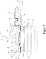
- Fig. 1 shows how in a first method step a component 14 to be applied is removed from a stack 12 by a manipulator 10 by the manipulator 10 sucking in the component 14 to be applied.
- the manipulator 10 is connected to a first vacuum pump 16.
- the manipulator 10 also has a support element 11 designed as a support plate, which has at least one through-channel 18 which is connected to the first vacuum pump 16. Air, which is located between a membrane 26 and the support element 11, is withdrawn through the passage 18, so that the membrane 26, as in FIG Figure 1 shown, moves or expands in the direction of the support element.
- the displacement or expansion of the membrane 26 in the direction of the support element 11 takes place when the support element 11 rests against the component 14 in a sealing manner, with a first sealing element 24 being arranged between the support element 11 and component 14, which also separates the membrane 26 from the support element 11 holds in such a way that it initially rests against component 14.
- the air is preferably withdrawn via one or more air passage structures 30, which are arranged on the support element surface 22 or adjacent to it, so that the membrane 26 expands within the first distance 32 between support element 11 and component 14 and in one then forming the first partial gap 20a a negative pressure and this achieves a suction of the component.
- the negative pressure that forms in the first partial gap 20a in turn causes a further negative pressure in a second partial gap 20b, which is formed between membrane 26 and component 14.
- This second sub-space 20b is laterally sealed by the membrane located between the support element 11 and component 14 or, optionally, by additional sealing elements 24 between the membrane 26 and the support element 11.
- the first distance 32 is selected such that the membrane can move sufficiently far away from the suction surface of the component 14 and can generate a corresponding first negative pressure there.
- the aim is to prevent the membrane 26 from resting over the entire surface of the support element surface 22 of the support element 11 and the first negative pressure not being sufficient to be able to lift the component 14 safely.
- the membrane 26 is preferably clamped in a frame 36 and mounted there in a sealing manner by means of fastening elements 38.
- a welt is preferably used here, which is fastened all around in a groove or a rail on the frame 36.
- the frame 36 has second through channels 39 with the aid of which (cf. Fig. 2 ) a second air stream 48 can be fed to a vacuum pump 42 in order to generate a second negative pressure in a second intermediate space 46.
- the first sealing elements 24 can also be dispensed with (cf. also Fig. 3 ) as soon as the support element 11 dips sufficiently far into the frame 36, ie reaches a penetration depth D of, for example, ⁇ 1 mm, preferably ⁇ 5 mm, particularly preferably ⁇ 10 mm.
- a penetration depth D of, for example, ⁇ 1 mm, preferably ⁇ 5 mm, particularly preferably ⁇ 10 mm.
- the membrane 26 is perforated, semipermeable or perforated (not shown), so that the negative pressure that develops in the first partial space 20a also develops directly in the second partial space 20b and as a result, the component 14 is sucked on the support element 11.
- the component 14 is arranged on a component 40 by means of the manipulator 10, the frame 36 carrying second sealing elements 37 which seal the frame 36 with respect to the component 40.
- a second intermediate space 46 develops between the frame 36, the component 40 and the support element 11 or the membrane 26, which is stretched in the frame 36 and, if necessary, is stretched over the support element 11 via first sealing elements 24 and holds the component 14 in an absorbent manner .
- the first air flow 44 can be reduced or even switched off, while the second air flow 48 already ensures a negative pressure in the second intermediate space 46 before it is fixed or adhered in order to avoid any air inclusions between the component 14 and the component 40 to be reduced or avoided entirely.
- the component 14 can then be attached to the component 40 over the entire surface, in particular glued, without air inclusions occurring.
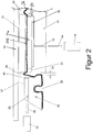
- Fig. 2 shows the fastened state in which the membrane 26 again rests against the component 14 with the component 14 spaced from the support element 11 and is pulled in the direction of the component 40 by the second negative pressure in the second intermediate space 46.
- a second distance 34 is advantageously provided between the support element 11 and the frame 36 of the manipulator 10, which distance prevents the support element 11 from moving and colliding with the frame 36.
- the component 14 is the same size or smaller than the support element 11, which prevents the diaphragm 26 from resting when the second negative pressure is generated in the second intermediate space 46 and ensures that the air is safely discharged by the second air flow 48 to the second vacuum pump 42.
- Fig. 3 shows how Fig. 2 the adherence of the component 14 to the component 40, the support element 11 being shown here with a removable air passage structure 30 (slightly raised), which is optionally arranged on the support element surface 22 via a seal 25 with respect to the support element 11.
- the detachable air passage structure 30 is arranged in an exchangeable manner attached to the support element 11 via guide and fastening elements (only shown schematically here), such as pins, screws, snap locks or the like.
- Fig. 3 shows two versions R, L of an air passage structure 30 with a correspondingly suitable membrane 26 of a preferred embodiment of the invention.
- a first version R shown to the right of a dashed dividing line and a second version L, shown to the left of the dashed dividing line.
- the air passage structure 30 has partial channels 19, which are permeable to the membrane 26, form the first partial intermediate space 20a there and discharge the air in the direction of the vacuum pump 16.
- the membrane 26 seals against the exchangeable air passage structure 30 at its edges and is attracted by the first negative pressure, so that a further negative pressure is generated between membrane 26 and component 14.
- the air passage structure 30 has partial channels 19 which are permeable to the membrane 26, form the first intermediate space 20 there and discharge the air in the direction of the vacuum pump 16.
- the membrane 26 is perforated, that is to say has holes and in the process seals against the exchangeable air passage structure 30 at its edges.
- the component 14 is sucked in by the negative pressure generated in the first interspace 20 and adheres to the air passage structure 30.
- the membrane 26 seals the first interspace from the outside world.
- the main advantage of this second version is the error detection: If the component 14 falls off, so the resulting negative pressure drop at the Vacuum pump 16 or a pressure sensor (not shown) can be detected immediately and the further movement of the manipulator is stopped.
- the air passage structure 30 is arranged in a sealing manner on the support element surface 22 of the support element 11, at the ends of which a seal 25 is shown.
- the air passage structure 30 can be provided interchangeably on the support element 11 in order to be able to implement different suction points on the support element 11 or suction surfaces for different components 14.
- the membrane 26 is stretched here via a fastening element 38 designed as a piping and fixed in a groove of the frame 36 and can thus stretch over the air passage structure (30) on the support element 11.
- the corners and edges 54 of the air passage structure 30 are preferably rounded in order to prevent damage to the tensioned membrane 26. It is also possible, however, to raise the corners and edges 54 of the air passage structure 30 somewhat in the direction of the component to be lifted, i.e.
- Sealing elements 24 shown are thus optional and, as in FIG Fig. 3 shown, can also be omitted if the membrane 26 is sufficiently tensioned and thereby assumes the sealing effect between the support element and the component.
- the frame 36 is arranged in particular circumferentially, ie in particular circular or rectangular, around the support element 11.
- the support element 11 is advantageously arranged movably in the direction of the component 40 with respect to the frame 36, i.e. in addition to or independently of the second negative pressure, the component 14 can move in the direction of the component 40 after the frame 36 has been arranged on the component 40, for example by springs is supported in the frame 36 or guided in relation to a frame housing 56 in order to be able to execute a relative movement of the support element 11 in the frame 36, essentially orthogonally to the component 40
- Fig. 4 16 shows an air passage structure 30.
- the air passage structure 30 can be attached to the support element surface 22.
- the air passage structure 30 preferably consists of a rigid, partially elastically deformable or completely elastically deformable material, such as a metal grid structure, a rubber, a silicone, an elastically deformable plastic, a sponge structure or the like.
- the air passage structure 30 is attached to a receiving element (not shown), which in turn is attached to the support element surface 22.
- a receiving element can, for example, have a predefined three-dimensional structure, which is in particular complementary to the component 40.
- Attaching the air passage structure 30 and / or the first sealing element 24 to the receiving element enables continuous air evacuation when a negative pressure is applied, so that the component to be applied with the membrane in between assumes the shape of the receiving element. In this way, even when using a preformed receiving element (not shown), it can be ensured that a particularly uniform distance between the receiving element and the sucked-in component 14 to be applied is maintained, so that an air flow 44 can be maintained during the sucking-in.
- Fig. 5 shows one opposite Fig. 3 slightly modified further embodiment of the invention.
- the support element 11 is shown with a removable air passage structure 30 (this time only a variant and in the assembled state), which is likewise arranged in a sealing manner with respect to the support element 11 on the support element surface 22 facing the membrane 26 by means of a seal 25.
- the removable air passage structure 30 is arranged to be exchangeably fastened to the support element 11 by means of guide and fastening elements (not shown here), such as pins, screws, snap locks or the like, or by means of the seal 25.
- the air passage structure 30 has sub-channels 19, which are here in connection with negative pressure areas 20c, which form different negative pressure areas or zones between the support element 11 and the component 14 by means of sealing area lips 24a, 24b.
- negative pressure zones which can be arranged in any way on the support element surface 22, different requirements when applying components 14, their weight, fragility, etc. can be addressed individually.
- the membrane 26 extending over these negative pressure zones can be both air-permeable and air-tight, depending on the preferred type of application.
- the air is thus discharged from the negative pressure regions 20c by means of the sub-channels 19 in the direction of the vacuum pump 16.
- the membrane 26 seals the negative pressure regions 20c, which in the case of an air-permeable membrane 26 extend up to the component 14, from the component 14 by means of the sealing region lips 24a, 24b.
- the air passage structure 30 is arranged in a sealing manner on the support element surface 22 of the support element 11, at the ends of which the seal 25 is in turn shown.
- the air passage structure 30 can be provided interchangeably on the support element 11 in order to be able to implement different negative pressure regions 20c on the support element 11 or suction surfaces for different components 14.
- the membrane 26 is again stretched over a fastening element 38 designed as a welt and fixed in a groove in the frame 36 and can thus stretch over the air passage structure 30, in particular over the sealing area lips 24a, 24b on the air passage structure 30.
- Fig. 5 schematically, springs 52 with the aid of which the support element 11 is resiliently mounted in the frame 36.
- the support element 11 is movably supported in the frame 36 by means of one or more pins 58 attached to the support element 11, which are slidably mounted in one or more bearings 55 on or in a frame housing 56 shown schematically.
- the specific embodiment shown is a centrally arranged pin 58 which is used in a bearing 55 in the frame housing 56 at the same time to accommodate the first through-channel 18, so that the air is safely discharged or removed even with a support element 11 moving relative to the frame 36 or frame housing 56 can be extracted.
- the support element 11 can essentially Slide resiliently orthogonally to component 40 in frame 36.
- the second distance 34 between the support element 11 and the frame 36 prevents possible damage to the membrane 26 as a result of the relative movement between the support element 11 and the frame 36.
Landscapes
- Engineering & Computer Science (AREA)
- Mechanical Engineering (AREA)
- General Engineering & Computer Science (AREA)
- Manipulator (AREA)
Description
- Die vorliegende Erfindung betrifft in Verfahren zum Applizieren, insbesondere zum Anpressen, einer Komponente an einem Bauteil mittels eines Manipulators.
- Im Bereich des Fahrzeugbaus werden oftmals Komponenten, insbesondere Folien, Pads oder dergleichen, insbesondere zur Körperschalldämpfung, per Hand befestigt oder mittels eines Roboters an einem Karosseriebauteil appliziert. Bei einem zu hohen Anpressdruck besteht hierbei das Risiko einer Verformung des Karosseriebauteils, während bei einem zu niedrigen oder ungleichmäßigen Anpressdruck es zu Lufteinschlüssen unter der zu applizierenden Komponente, insbesondere unter der zu applizierenden Folie oder des Pads, kommen kann, insbesondere wenn diese vollflächig angeklebt werden soll, was bei Dämpfungsapplikationen erwünscht ist. Bei Verwendung eines zu niedrigen oder ungleichmäßigen Anpressdrucks oder falls es zu Lufteinschlüssen kommt, kann es ferner dazu kommen, dass in einem weiteren Produktionsschritt, wie beispielsweise das Eintauchen des Karosseriebauteils in einem Lackbad oder dergleichen, es zur Abtrennung zwischen der Komponente und dem Karosseriebauteil kommen kann, z.B. weil Flüssigkeit zwischen die Komponente und das Bauteil fließt und die Klebung auflöst.
- Aus der
EP 0 986 457 A1 ist eine Vorrichtung zum Anbringen einer akustisch wirksamen Folie bekannt geworden. Die Vorrichtung wird zum Anbringen einer Folie auf ein Bauteil verwendet, wobei die Vorrichtung einen geschlossenen Rahmen umfasst, welcher mit einer flexiblen Membran zum Halten und Applizieren der Folie ausgebildet ist. Die Folie wird hierbei zunächst auf der flexiblen Membran angeordnet. Die Membran wird über einer konkaven Auflage am Rahmen befestigt. Zum Anbringen an einem Bauteil wird Luft, welche sich zwischen der Folie und dem Bauteil befindet, abgesaugt. Hierfür liegt der Rahmen dichtend am Bauteil an, weiterhin sind an dem Rahmen Unterdrucköffnungen zum Absaugen der Luft vorgesehen. Durch die flexible Membran, auf welcher die Folie aufgelegt ist und welche in ihrer Ruhestellung zu einer Seite des Bauteils hin konvex gekrümmt verläuft, wird die Folie zunächst aufgenommen und angehoben und in einem weiteren Schritt, in dem die Folie an das Bauteil angebracht werden soll, wird die Membran mit der Folie an das Bauteil herangeführt, indem die Luft, welche sich zwischen dem Bauteil und der Membran befindet, durch die Unterdrucköffnungen abgesaugt wird. Hierdurch legt sich die Membran an die Folie und das Bauteil schmiegend an. Dabei kann es dazu kommen, dass sich die Membran am Bauteil anlegt und die weitere Luftabfuhr unterbleibt, so dass zwischen der Folie und dem Bauteil Lufteinschlüsse bilden. Außerdem muss die Folie vorher umständlich per Hand auf die Membran gelegt und genau ausgerichtet werden. Senkrechte Befestigungen oder Befestigungen, bei welchen der Manipulator die Folie von oben nach unten aufbringt, z.B. am Boden des Fahrgastraums eines KfZ, sind i.d.R. nicht möglich, weil die Folie sonst beim Verschwenken des Manipulators von der Auflage abfällt. - Weiterhin offenbart die
FR 2848976 - Der vorliegenden Erfindung liegt daher die Aufgabe zu Grunde, ein Verfahren bereitzustellen, mit dem eine Komponente mittels eines Manipulators an einem Bauteil automatisch appliziert werden kann, wobei die Probleme des Stands der Technik vermieden werden.
- Diese Aufgabe wird gelöst mit einem Verfahren zum Applizieren, insbesondere zum Anpressen, einer Komponente an einem Bauteil gemäß Anspruch 1 und mittels einer Vorrichtung nach Anspruch 15. Weitere Vorteile und Merkmale der vorliegenden Erfindung ergeben sich aus den abhängigen Ansprüchen.
- Nach einer zweiten alternativen Ausführungsform der Erfindung ist der erste Teilzwischenraum und der zweite Teilzwischenraum luftleitend verbunden, d.h. der ersten Zwischenraum ist ein luftleitend verbundener Raum, so dass sich der im ersten Teilzwischenraum erzeugte Unterdruck, d. h. der Unterdruck zwischen dem Stützelement und der Membran, sich in den zweiten Teilzwischenraum fortsetzt und so unmittelbar auf die Komponente wirkt. Bei dieser zweiten alternativen Ausführungsform kann auf die ersten Dichtelemente verzichtet werden, die bei der ersten alternativen Ausführungsform vorhanden sind, da in diesem Fall die Membran selbst unmittelbar zwischen Stützelement und Komponente zu liegen kommt und den ersten Zwischenraum zwischen Komponente und Stützelement umlaufend abdichtet. Im ersten Zwischenraum selbst ist die Membran bevorzugt mit einer Perforation, Löchern oder Öffnungen ausgestattet, so dass sich der Unterdruck unmittelbar auf die Komponente auswirkt und diese gegen das Stützelement presst. Luft von außen kann nicht einfließen, da die Membran selbst zwischen dem Stützelement und der Komponente den Unterdruck im ersten Zwischenraum zwischen Komponente und Stützelement abdichtet.
- Damit die Membran die Komponente gegenüber dem Stützelement auch ohne zusätzliche erste Dichtelemente abdichtet, ist es vorgesehen, dass die Membran vorgespannt wird oder mittels eines Eindringens des Stützelements in einen umlaufenden Rahmen, in den die Membran eingespannt ist, gespannt wird, so dass es mittels umlaufender Dichtwirkung der Membran an den Rändern zwischen Stützelement und Komponente zur wirksamen Abdichtung des Unterdrucks im Zwischenraum zwischen der Komponente und dem Stützelement kommt.
- Bei der ersten alternativen Ausführungsform der Erfindung kann der Manipulator mehrere mit ersten Dichtelementen oder Dichtbereichslippen abgeschlossene Bereiche am Stützelement aufweisen, die jeweils mit einer Membran überzogen sind, sodass über den Manipulator bzw. das Stützelement verteilt mehrere Haltebereiche entstehen, mit Hilfe deren die Komponente an mehreren Stellen saugend befestigt und dadurch angehoben werden kann. In diesem Fall sind die einzelnen Bereiche der Stützfläche jeweils einzeln mit ersten Dichtelementen oder Dichtbereichslippen umlaufend abgedichtet, so dass ein sich dann insbesondere mittels einer Vakuumpumpe einstellender Unterdruck zwischen der Membran und dem entsprechenden Bereich des Stützelements, der beispielsweise mittels im Stützelement angebrachten ersten Durchgangskanälen erzeugt werden kann, die Membran in Richtung des Stützelements bewegt und dadurch einen entsprechenden Unterdruck im ersten Zwischenraum zwischen Membran und Komponente erzeugt da dieser erste Zwischenraum über die ersten Dichtelemente abgedichtet ist.
- Alternativ kann aber auch das Stützelement an der der Membran zugewandten Stützelementfläche Bereiche aufweisen, insbesondere eine Luftdurchlassstruktur, die derart gestaltet sind, dass sie allein mittels der Membran beim Auflegen auf die Komponente luftdicht abschließen, beispielsweise durch leichte Erhebungen oder Rundungen an den Rändern dieser Bereiche oder durch eine dicke, flexible Membran. Besonders bevorzugt weist das Stützelement dabei eine auswechselbare Luftdurchlassstruktur, also eine auswechselbare Stützelementfläche, auf, so dass je nach anzuhebender Komponente die Luftdurchlassstruktur mit oder ohne Dichtelemente oder Dichtlippen an die Komponente angepasst verwendet werden kann. Mit Vorteil befinden sich dabei zwischen der der Membran zugewandten Stützelementfläche und abnehmbarer Luftdurchlassstruktur Dichtelemente sowie geeignete Führungs- und Befestigungselemente zur sicheren Führung und Befestigung der Auswechselbaren Luftdurchlassstruktur.
- 2. Bewegen des Manipulators mit Komponente zu dem Bauteil.
- Durch das Ansaugen der Komponente mit Hilfe des Unterdrucks in dem mindestens einen ersten Zwischenraum kann die Komponente vom Stapel angehoben und mittels des Manipulators zu dem Bauteil bewegt werden.
- 3. Anordnen der Komponente an zumindest einer Teilfläche des Bauteils mittels des Manipulators, wobei während des Anordnens ein zweiter Unterdruck in einem zweiten Zwischenraum zwischen dem Stützelement und dem Bauteil erzeugt wird.
- Sobald die Komponente das Bauteil erreicht, wird der Manipulator mit Hilfe von zweiten Dichtelementen gegen das Bauteil gedrückt und es entsteht ein zweiter Zwischenraum zwischen dem Bauteil, dem Rahmen des Manipulators und der Membran, die auf dem Stützelement gespannt aufliegt und die mittels des ersten Unterdrucks in Richtung des Stützelements gespannt ist, so dass die Komponente immer noch saugend am Stützelement befestigt ist. Zuvor kann die zu applizierende Komponente mit einem Klebstoff an der Bauteilseite versehen werden, um die Komponente klebend am Bauteil zu befestigen. Der Kleberauftrag kann entweder durch Abziehen einer Schutzfolie an der Bauteilseite der Komponente erfolgen, so dass eine Kleberschicht frei wird, die auf der Komponente aufliegt, oder durch das Aufbringen einer separaten Kleberschicht, beispielsweise indem der Manipulator zuvor über eine mit einem Kleber ausgestattete Rolle fährt und die Bauteilseite der Komponente entsprechend mit einer Kleberschicht ausstattet.
- Sobald der zweite Zwischenraum mittels der zweiten Dichtelemente hergestellt ist, die insbesondere zwischen dem Rahmen des Manipulators und dem Bauteil zu liegen kommen, wird ein zweiter Unterdruck erzeugt, indem die Luft in dem zweiten Zwischenraum abgezogen wird. Dies kann beispielsweise durch zweite Durchgangskanäle im Rahmen erfolgen, die wiederum mit einer Vakuumpumpe oder einer Venturidüse verbunden sind. Durch die Erzeugung eines zweiten Unterdrucks im zweiten Zwischenraum wird die Membran mit der Komponente wieder, entgegen der Richtung hin zum Stützelement, in Richtung des Bauteils gezogen und die Membran entfernt sich mit der Komponente vom Stützelement in Richtung auf das Bauteil. Sobald die Komponente jedenfalls teilweise am Bauteil festgelegt ist, beispielsweise durch ein erstes Anhaften bevorzugt mittig, wird der zweite Unterdruck weiter erhöht und/oder der erste Unterdruck reduziert. Ggf. zieht der zweite Unterdruck, sofern dessen auf die Membran einwirkende Kraft größer ist als die des ersten Unterdrucks, die Membran von der dichtenden Anlage am Stützelement bzw. der Luftdurchlassstruktur bzw. der dort angebrachten Dichtelemente ab, so dass der erste Unterdruck zum Erliegen kommt.
- Um insbesondere ein ungewolltes Abfallen der Komponente vor dem sicheren Anhaften am Bauteil zu vermeiden bzw. um ungewollte Kräfte auf das Stützelement durch den zweiten Unterdruck zu vermeiden, ist es nach einer weiteren Ausführungsform der Erfindung vorgesehen, dass das Stützelement gegenüber dem Rahmen federnd gelagert ist, so dass das Stützelement im Rahmen eine im wesentlichen senkrecht zum Bauteil gerichtete Relativbewegung ausführen kann. Die Federkraft ist mit Vorteil dabei schwächer als die Kraft des ersten Unterdrucks, so dass ein Abfallen der Komponente vermieden wird, wenn der zweite Unterdruck größer als der erste Unterdruck wird und die Komponente noch nicht sicher am Bauteil anhaftet.
- 4. Befestigen der Komponente am Bauteil durch Erhöhen der Differenz zwischen dem ersten und zweiten Unterdruck.
- Der Manipulator hält nach einer Ausführungsform der Erfindung den ersten Unterdruck bis nach dem erfolgten Anordnen und zumindest teilweisen Befestigung der Komponente am Bauteil kontinuierlich aufrecht. Die Komponente wird dabei von der Membran in Position gehalten, bis sie am Bauteil durch den zweiten Unterdruck, vorzugsweise von der Mitte der Komponente hin zum Rand sukzessive festgeklebt bzw. befestigt wird bzw. dort anhaftet. Diese Übergabe wird bevorzugt durch ein Stützelement unterstützt, dass gegenüber dem Rahmen federnd gelagert ist.
- Der erste Unterdruck kann nach einem ersten Teilbefestigen der Komponente vollständig abgeschaltet werden oder sogar mittels eines Überdrucks den zweiten Unterdruck unterstützen, wobei der zweite Unterdruck bevorzugt die Luft aus dem zweiten Zwischenraum entzieht, wodurch die Wahrscheinlichkeit von Lufteinschlüssen zwischen der Komponente und dem Bauteil reduziert wird.
- Nach der vorliegenden Erfindung wird also zunächst eine zu applizierende Komponente mittels des Manipulators, an welchem mit Vorteil eine Vakuumpumpe angeschlossen ist, angesaugt. Anschließend wird der Manipulator mit angesaugter Komponente zu dem Bauteil bewegt, an dem die angesaugte Komponente appliziert werden soll. Die zu applizierende Komponente wird zumindest an einer Teilfläche des Bauteils mittels des Manipulators angeordnet, insbesondere über eine Fläche gleichmäßig angepresst, wobei der Manipulator das Ansaugen der zu applizierenden Komponente jedenfalls bis nach einem ersten Anhaften der Komponente am Bauteil kontinuierlich aufrecht erhält. Vor und/oder während des Anordnens wird bevorzugt ein Unterdruck, insbesondere durch das Absaugen von Luft, in dem zweiten Zwischenraum zwischen dem Bauteil und dem Manipulator erzeugt. In diesem Zwischenraum befindet sich die zu applizierende Komponente.
- Anschließend wird die Komponente durch den Manipulator losgelassen, indem der Manipulator das Ansaugen, jedenfalls vorübergehend, durch Reduktion oder Abschalten des ersten Unterdrucks unterbricht. Bevorzugt weist der Manipulator eine Ansaugfläche auf, insbesondere ein als Stützplatte ausgeformtes Stützelement, mit welcher die zu applizierende Komponente angesaugt wird, wobei die Ansaugfläche des Stützelements bevorzugt kleiner ausgebildet ist als eine Ansaugfläche der anzusaugenden Komponente.
- Bei dem vorgeschlagenen Verfahren kann in vorteilhafter Weise eine zu applizierende Komponente zunächst mittels des Manipulators von einem Stapel, auf dem eine Vielzahl zu applizierender Komponenten aufeinander angeordnet sind, angesaugt werden. Durch das Ansaugen einer zu applizierenden Komponente von einem Stapel als solches wird die anzusaugende Komponente sicher und schonend vom Manipulator ergriffen. Durch das Ansaugen mittels einer Vakuumpumpe, welche an dem Manipulator angeschlossen ist, kann die zu applizierende Komponente zerstörungsfrei von dem Stapel abgenommen werden. Dazu kann der Manipulator zur Erzeugung des ersten Unterdrucks die Komponente zunächst leicht gegen den Stapel drücken, so dass ein erstes Dichtelement, das sich zwischen einem Stützelement des Manipulators und der Komponente befindet, oder die Membran selbst, sofern keine ersten Dichtelemente sondern z.B. eine gelochte Membran verwendet wird, dichtend abschließt.
- Nach der Entnahme einer zu applizierenden Komponente kann der Manipulator die angesaugte zu applizierende Komponente flexibel an einem Bauteil positionieren. Nach dem Anordnen bzw. Positionieren der zu applizierenden Komponente und insbesondere nach einem ersten Fixieren bzw. Anhaften der Komponente am Bauteil kann mit Hilfe des nachlassenden ersten Unterdrucks zwischen dem Manipulator und dem Bauteil die zu applizierende Komponente an das Bauteil angeschmiegt bzw. angeklebt und dann losgelassen werden. Der zweite Unterdruck hält die Komponente dabei selbst bei nachlassendem oder wegfallendem ersten Unterdruck in Position.
- Bevorzugt wird der für das Ansaugen der zu applizierenden Komponente erzeugte erste Unterdruck nach dem Anordnen und nach einem ersten Fixieren der zu applizierenden Komponente an dem Bauteil bis zu einem Erreichen eines Umgebungsnormaldruckes sukzessive reduziert. Es kann ferner vorgesehen sein, dass der für das Ansaugen erzeugte Unterdruck in einen gegenüber dem Umgebungsdruck höheren Druck (Überdruck) gewandelt wird, wodurch es möglich ist, die zu applizierende Komponente an einem Bauteil anzuformen, das mit einem dreidimensionalen Relief ausgestattet ist oder gekrümmt oder gebogen ist. Alternativ oder zusätzlich kann ein gefedertes Stützelement verwendet werden, so dass eine Bewegung der Komponente hin zum Bauteil bei beginnendem zweiten Unterdruck gewährleistet wird, selbst wenn der erste Unterdruck, insb. zur Sicherung der Komponente, noch nicht nachgelassen oder abgeschaltet wird.
- Je nach zu applizierender Komponente kann der erste und zweite Unterdruck bzw. ein Überdruck im ersten Zwischenraum so gesteuert werden, dass die Komponente sukzessive von einem Mittelbereich der Komponente hin zu einem Außenbereich am Bauteil angeklebt wird, so dass keine oder nur sehr geringe Lufteinschlüsse zwischen der Komponente und dem Bauteil verbleiben. Entscheidend ist jedoch, dass am Rand der Komponente eine vollflächige Verklebung mit dem Bauteil erfolgt, d. h. dass keinerlei Flüssigkeiten, Luft, Gase oder andere Stoffe zwischen die Komponente und das Bauteil gelangen, was bei einem späteren Lackbad oder dergleichen von Vorteil ist, da die Komponente dann sicher am Bauteil klebt bzw. befestigt ist und nicht mehr abfallen kann.
- Durch die Reduktion des ersten Unterdrucks bzw. den Wiederaufbau eines Umgebungsnormaldruckes bzw. eines Überdruckes relativ zum Umgebungsnormaldruck im ersten Zwischenraum bzw. durch die Erzeugung des zweiten Unterdrucks im zweiten Zwischenraum kann die zu applizierende Komponente zerstörungsfrei an dem Bauteil angeordnet werden. In vorteilhafter Weise wirken die Drücke gleichmäßig auf einer Teilfläche des Bauteils, welche von dem Manipulator abgedeckt wird. In vorteilhafter Weise kann durch das quasi-automatische Anordnen, insbesondere Anpressen, der Komponente an das Bauteil, ein zu hoher, insbesondere lokaler, Anpressdruck oder ein ungleichmäßiger Anpressdruck vermieden werden. Hierdurch wird das Risiko einer Verformung des Bauteils vermindert. Weiterhin wird durch die Erzeugung des zweiten Unterdrucks ein Einschluss von Luft zwischen Komponente und Bauteil vermindert, ggf. vermieden.
- Vorliegend ist unter Bauteil insbesondere ein Blech oder ein Karosseriebauteil eines Fahrzeugs zu verstehen. Beispielsweise könnte die zu applizierende Komponente eine insbesondere selbstklebende Alu-Butylkombination sein, welche bereits im Rohbau auf geölten Flächen eingesetzt werden können. Ferner könnte mit dem vorgeschlagenen Verfahren eine Komponente an ein Bauteil appliziert werden, welches beispielsweise im Bereich der Luft- und Raumfahrttechnik, der Elektronik im Haushaltswarenbereich oder in sonstigen Herstellungsverfahren, in denen Manipulatoren verwendet werden, benutzt werden. Es ist ferner denkbar, dass die zu applizierende Komponente aus einer anderen selbstklebenden Materialkombination oder nichtklebenden Materialkombinationen besteht oder beispielsweise auch im Hochbau, z.B. zum Anbringen von Fensterflächen, Fassadenelementen oder dgl. genutzt wird.
- Nach einer weiteren Ausführungsform der Erfindung wird der erste Unterdruck in dem zweiten Teilzwischenraum mittels einer Membran erzeugt, die zwischen der Komponente und dem Stützelement dichtend angeordnet ist und die auf der dem Stützelement zugewandten Seite mit einer Vakuumpumpe luftleitend in Verbindung steht. Nach einer Ausführungsform der Erfindung übernimmt allein die luftdurchlässige Membran die Dichtfunktion zwischen Stützelement und Komponente, so dass auf zusätzliche Dichtelemente oder Dichtlippen verzichtet werden kann.
- Der erfindungsgemäße Manipulator weist mit Vorteil ein Stützelement auf, das an einer oder mehreren Stellen entsprechende mittels ersten Dichtelementen abgeschlossene erste Teilzwischenräume aufweist, die luftleitend mit Durchgangskanälen verbunden sind, die mit einer Vakuumpumpe luftleitend in Verbindung stehen. Mit Vorteil weist das Stützelement dabei an der der Membran zugeordneten Seite Luftdurchlassstrukturen, wie beispielsweise Gitter, auf durch die die Luft aus dem ersten Teilzwischenraum zwischen Membran und Stützelement abgesaugt werden kann, wodurch sich die Membran in Richtung des Stützelements bewegt und einen ersten Unterdruck zwischen der Membran und der anzusaugenden Komponente erzeugt. Im Gleichgewichtsfall ist dabei der Unterdruck zwischen dem Stützelement und der Membran gleich groß wie zwischen der Membran und der Komponente, d. h. zwischen dem Stützelement und der Komponente existiert ein erster Abstand, der durch das erste Dichtelement erzeugt wird. In diesem Abstand kann sich die Membran verschieben; diese ist flexibel und dehnbar und folgt einem Unterdruck zwischen Membran und Stützelement, so dass sich der erste Unterdruck zwischen Membran und Komponente einstellt. Mittels der Luftdurchlassstruktur wird vermieden, dass bei einem Aufliegen der Membran auf dem Stützelement der Durchgangskanal verschlossen wird und keine weitere Luft abtransportiert werden kann.
- Nach einer zweiten bevorzugten Ausführungsform der Erfindung weist der erfindungsgemäße Manipulator ein Stützelement auf, das verschiebbar und ggf. federnd in einem Rahmen derart gelagert ist, dass sich eine Membran zwischen dem Stützelement und der anzusaugenden Komponente derart anordnet und strafft, dass es zu einer umlaufenden dichtenden Anlage des Stützelements an der anzusaugenden Komponente beim Aufbringen bzw. Aufliegen des Stützelements auf der Komponente kommt, wobei der vorgenannte erste Teilzwischenraum zwischen Stützelement und Membran ebenfalls luftleitend mit Durchgangskanälen verbunden ist, die mit einer Vakuumpumpe luftleitend in Verbindung stehen. Auch hier kann das Stützelement an der der Membran zugeordnete Seite Luftdurchlassstrukturen, wie beispielsweise Gitter, aufweisen. Durch die luftleitende Verbindung zwischen dem ersten Teilzwischenraum und dem zweiten Teilzwischenraum wird ein Unterdruck unmittelbar zwischen Komponente und Stützelement erzeugt. In diesem Unterdruck liegt die insbesondere mit Öffnungen oder Löchern ausgestattete Membran oder eine Membran, die luftdurchlässig in diesem Bereich ausgestaltet ist, an der Luftdurchlassstruktur oder dort angeordneten Dichtelementen an. In diesem Fall dient die Membran zwischen Stützelement und Komponente zur Abdichtung des Stützelements gegenüber der Membran und - nach dem Aufsetzen der Komponente am Bauteil - zur dichtenden Anordnung des Manipulatorrahmens am Bauteil und somit zur Erzeugung des zweiten Unterdrucks.
- Der Vorteil der zweiten bevorzugten Ausführungsform der Erfindung liegt insbesondere darin, dass auf erste Dichtelemente verzichtet werden kann und dass ein Fehler bei der Handhabung der Komponente, also beispielsweise ein Abfallen der Komponente sofort durch einen Abfall des Unterdrucks detektiert werden kann, was bei der ersten bevorzugten Ausführungsform nicht der Fall ist, da sich der Unterdruck im Wesentlichen im ersten Teilzwischenraum zwischen Stützelement und Membran ausbildet und ein Abfallen der Komponente nicht ohne weiteres durch Messung des dann fehlenden Unterdrucks detektiert werden kann.
- Nach einer weiteren Ausführungsform der Erfindung wird der zweite Unterdruck in dem zweiten Zwischenraum mittels eines am Bauteil dichtend angeordneten Rahmens des Manipulators erzeugt, wobei der zweite Zwischenraum luftleitend mit der Vakuumpumpe in Verbindung steht.
- Der zweite Zwischenraum, der zwischen Rahmen, Bauteil und Membran nach dem Anordnen des Manipulators am Bauteil entsteht, wird insbesondere durch zweite Durchgangskanäle erzeugt, die diesen zweiten Zwischenraum mit der Vakuumpumpe oder einer separaten Vakuumpumpe verbinden.
- Nach einer weiteren Ausführungsform der Erfindung wird der zweite Zwischenraum durch den Rahmen, das Bauteil und das Membran begrenzt, und die Komponente kommt nach dem Anordnen in dem zweiten Zwischenraum zu liegen.
- Indem die Komponente in dem zweiten Zwischenraum zu liegen kommt, wird diese beim Erzeugen des zweiten Unterdrucks mit Hilfe der Membran in Richtung des Bauteils verschoben, wobei der zweite Unterdruck dem ersten Unterdruck entgegen wirkt bzw. nach einem ersten Anhaften der erste Unterdruck abgeschaltet werden kann, so dass der zweite Unterdruck ausreicht, um die Komponente vollflächig am Bauteil zu verkleben.
- Nach einer weiteren Ausführungsform der Erfindung weist das Stützelement mindestens einen Durchgangskanal auf, der mit der Vakuumpumpe und mindestens einer der Membran zugewandten Luftdurchlassstruktur luftleitend in Verbindung steht, wobei die Membran über mindestens ein erstes Dichtelement gegenüber dem Stützelement jedenfalls im Bereich der mindestens einen Luftdurchlassstruktur dichtend beabstandet wird, wobei Luft zwischen der Membran und dem Stützelement entfernt wird, so dass sich die Membran zum Stützelement hin bewegt, so dass im ersten Zwischenraum ein Unterdruck entsteht.
- Nach einer weiteren Ausführungsform der Erfindung weist die Komponente eine Ansaugseite auf, mit der die Komponente flächig von dem Manipulator angesaugt wird und eine gegenüberliegende, insbesondere klebende Bauteilseite, mit der die Komponente an dem Bauteil angeordnet, insbesondere angepresst und angeklebt, wird.
- Diese Ansaugseite ist bevorzugt derart gestaltet, dass eine luftdichte Verbindung zwischen Ansaugseite der Komponente und Membran entsteht, die auf dem ersten Dichtelement aufliegt und insoweit beispielsweise durch ein elastisches Dichtelement zwischen Dichtelement und Komponente eingeklemmt und insoweit dichtend befestigt wird. Da sich die Membran in diesem Fall über dem Zwischenraum zwischen Stützelement und Komponente spannt, muss diese flexibel, d. h. dehnbar, gestaltet sein, um eine Auslenkung in Richtung des Stützelements zu gewährleisten und um den ersten Unterdruck erzeugen zu können.
- Nach einer weiteren Ausführungsform der Erfindung wird die mindestens eine Luftdurchlassstruktur (30) auf der der Membran (26) zugewandten Außenseite des Stützelements (11) angebracht, angeformt oder auswechselbar angeordnet.
- Nach einer weiteren Ausführungsform der Erfindung wird der zweite Unterdruck mittels eines Anordnens der Komponente an dem Bauteil mittels mindestens eines zweiten Dichtelements erzeugt, das zwischen dem Rahmen des Manipulators und dem Bauteil zu liegen kommt, so dass der zweite Zwischenraum entsteht. Das Befestigen der Komponente am Bauteil erfolgt in einem ersten Schritt durch Reduktion des ersten und/oder Erhöhen des zweiten Unterdrucks, so dass die Komponente zumindest teilweise am Bauteil anhaftet und in einem zweiten Schritt durch eine weitere Reduktion des ersten und/oder Erhöhen des zweiten Unterdrucks und/oder Abschalten des ersten Unterdrucks.
- Nach einer weiteren Ausführungsform der Erfindung ist das erste Dichtelement ggf. zusammen mit der mindestens einen Luftdurchlassstruktur am Stützelement insbesondere auswechselbar und mit Vorteil umlaufend angeordnet.
- Das Stützelement kann nach der ersten bevorzugten Ausführungsform der Erfindung mehrere Bereiche aufweisen, die mit ersten Dichtelementen umfassend bzw. umlaufend ausgestattet sind, über die einzelne oder eine gemeinsame Membran gespannt sein können. Bevorzugt ist die Membran über das gesamte Stützelement hinweg gespannt, während das Stützelement einen oder mehrere Bereiche mit ersten umlaufenden Dichtelementen aufweist, die jeweils am Stützelement angeordnete Luftdurchlassstrukturen, wie z. B. Öffnungen oder Gitter, umgeben. Die Membran ist dabei bevorzugt mittels eines Befestigungselements am Rahmen dichtend befestigt und über die ersten Dichtelemente über das mittig im Rahmen beabstandete Stützelement hinweg gespannt. Das Stützelement kann dabei bevorzugt auswechselbare Luftdurchlassstrukturen aufweisen, die ggf. mit ersten Dichtelementen umlaufend ausgestattet sind, so dass ein und dasselbe Stützelement mit ggf. mehreren Durchgangskanälen und Luftdurchlassstrukturen für mehrere Ansaugbereiche genutzt werden kann.
- Insbesondere beim Verzicht auf erste Dichtelemente ist eine Vorspannung der Membran insbesondere dadurch zu erzielen, als das Stützelement über eine gewisse Eindringtiefe in den Rahmen des Manipulators eintaucht, so dass die Membran, die in entsprechenden Keder des Rahmens gehalten wird, gespannt wird und somit dichtend zwischen Stützelement und Komponente zu liegen kommt.
- Nach einer weiteren Ausführungsform der Erfindung wird der erste Unterdruck mittels einer ersten Vakuumpumpe und der zweite Unterdruck mittels einer zweiten Vakuumpumpe erzeugt, und/oder der erste Zwischenraum wird über die Membran und einen Druckregler bzw. -minderer und/oder der zweite Zwischenraum über einen Druckregler mit einer Vakuumpumpe derart verbunden, dass der erste und zweite Unterdruck kontinuierlich oder stufenweise und mit Vorteil unabhängig voneinander erhöht oder vermindert werden können.
- Nach einer weiteren Ausführungsform der Erfindung ist der Rahmen und das Stützelement derart zueinander bzw. voneinander beabstandet, dass ein Berühren einer angesaugten Komponente durch den Rahmen unterbleibt.
- Zwischen das Stützelement und Rahmen ist bevorzugt ein zweiter Abstand vorgesehen, der ein Durchführen der Membran und ein Berühren der Komponente mit dem Rahmen verhindert. Gleichzeitig ist es vorteilhaft, das Stützelement in seiner Erstreckungsebene etwas kleiner zu dimensionieren als die Komponente, um ein sicheres Anfügen am Bauteil zu gewährleisten. Unter Erstreckungsebene versteht die Erfindung dabei im Wesentlichen die zweidimensionale Ausdehnung des Stützelements, da insbesondere eine flächige Komponente am Bauteil befestigt werden soll, d. h. die Breite und/oder die Länge des Stützelements sollte gleich groß oder kleiner sein als die entsprechende Breite bzw. Länge der Komponente.
- Nach einer weiteren Ausführungsform der Erfindung ist die Bauteilseite der Komponente mit einer Klebeschicht ausgebildet, welche beim Befestigen der Komponente an dem Bauteil mit dem Bauteil verbunden wird.
- Nach einer weiteren Ausführungsform der Erfindung erfolgt das Befestigen der Komponente an dem Bauteil ausgehend von einer Ansaugstelle, welche im Wesentlichen mittig an der Komponente liegt, bis zu einem Rand der Komponente durch Erhöhen der Differenz zwischen dem ersten und zweiten Unterdruck derart, dass die Komponente jedenfalls umlaufend ohne Lufteinschlüsse am Bauteil zu liegen kommt.
- Die Vorrichtung gemäß der Erfindung weist einen Manipulator zum gleichmäßigen Anpressen einer Komponente an insbesondere einer Fläche eines Bauteils auf, wobei der Manipulator die zu applizierende Komponente mittels eines ersten Unterdrucks aufnimmt, der in einem ersten Zwischenraum zwischen einem Stützelement und der Komponente erzeugt wird, der Manipulator die zu applizierende Komponente zu dem Bauteil bewegt, der Manipulator die Komponente an zumindest einer Teilfläche des Bauteils anordnet, wobei während des Anordnens ein zweiter Unterdruck in einem zweiten Zwischenraum zwischen dem Stützelement und dem Bauteil erzeugt wird, und wobei der Manipulator die Komponente am Bauteil zum Beispiel durch Erhöhen der Differenz zwischen dem zweiten und ersten Unterdruck insbesondere klebend befestigt.
- Gemäß einer bevorzugten Ausführungsform verläuft durch das Stützelement ein bevorzugt orthogonal zu einer Ansaugfläche des Stützelements, vorzugsweise im Wesentlichen mittig, angeordneter Durchgangskanal, in dem ein durch die Vakuumpumpe erzeugter Luftstrom zum Ansaugen der Komponente strömt. Durch Anordnung eines Durchgangskanals an einer mittigen Position durch das Stützelement hindurch, ist es möglich, die zu applizierende Komponente zunächst gegenüber dem Stützelement konvex anliegend an den Manipulator anzusaugen. Durch den abfallenden Druck zwischen dem Stützelement und der angesaugten Komponente (also durch Erzeugen des ersten Unterdruckes, insbesondere über die Vakuumpumpe), kann sich die zu applizierende Komponente zunächst an den Manipulator anschmiegen. Ferner kann durch den im Wesentlichen mittig angeordneten Durchgangskanal die Komponente im Wesentlichen an ihrem Schwerpunkt angesaugt werden. Durch Ansaugen des Schwerpunkts der zu applizierenden Komponente kann die zu applizierende Komponente sicher von dem Manipulator gehalten werden.
- Die zu applizierende Komponente weist eine Ansaugseite, mit der die Komponente flächig von dem Manipulator angesaugt wird, und eine gegenüberliegende Bauteilseite auf, mit der die Komponente an den Bauteil angeordnet, insbesondere angepresst, wird. Die Ansaugseite der Komponente ist nach dem Anordnen an dem Bauteil die an dem Bauteil frei zugängliche Seite der Komponente. Durch das Ansaugen der Komponente auf Basis von Luftdruckunterschieden kann die zu applizierende Komponente zerstörungsfrei an dem Bauteil angeordnet werden, insbesondere wirkt der auf die Komponente und das Bauteil ausgeübte Kraft während des Applizierens flächig.
- Bevorzugt ist der Manipulator mit einem auswechselbaren Stützelement zum Ansaugen der Komponente ausgebildet, welches bevorzugt zumindest teilweise komplementär zu einer Bauteilfläche ausgebildet ist, auf der die Komponente zu applizieren ist. Das Verwenden eines vorgeformten, insbesondere komplementär zum Bauteil vorgeformten, auswechselbaren Stützelements erlaubt es, die zu applizierende Komponente noch vor einem Anordnen an dem Bauteil vorzuformen, insbesondere zu biegen oder zu prägen. Hierdurch kann ein Anordnen der zu applizierenden Komponente an dem Bauteil zeiteffizienter durchgeführt werden. Die zu applizierende Komponente ist dabei mit Vorteil elastisch oder teilweise elastisch verformbar.
- Während des Ansaugens ermöglicht das erste Dichtelement - bei der ersten bevorzugten Ausführungsform der Erfindung - einen kontinuierlichen Luftstrom entlang dem Stützelement bzw. entlang der Stützelementfläche. Durch das erste Dichtelement wird ein Abstand zwischen Membran und Stützelement erzeugt und so eine Bewegung der Membran und der Komponente ermöglicht.
- Bevorzugt ist die Luftdurchlassstruktur ein starres Gitter oder in Form von, insbesondere gleichmäßig oder ungleichmäßig auf der Ansaugfläche des Stützelements oder dem auswechselbaren Stützelement verteilten Hervorhebungen, Nuten oder Gräben ausgebildet. Im Falle einer verformbaren oder elastisch verformbaren Luftdurchlassstruktur kann diese beispielsweise aus Metall oder Kunststoff oder einem schwammartigen Material gebildet sein. Im Fall von Hervorhebungen können diese beispielsweise aus Silikon oder Gummi oder einem anderen verformbaren Material ausgebildet sein, welche basierend auf einen Krafteinfluss, wie beispielsweise einem Unterdruck verformbar sind. Bevorzugt ist mit dem ersten Dichtelement ein erster Abstand von 0-10mm, vorzugsweise von 0,2-5mm, besonders bevorzugt 2-3mm zwischen dem Stützelement und der Komponente einstellbar. Durch diesen Abstand wird ein kontinuierlicher Luftstrom zwischen der an dem ersten Dichtelement anliegenden Membran mit der zu applizierenden Komponente und dem Stützelement bzw. der Stützelementfläche ermöglicht.
- Bevorzugt ist der erste Abstand zwischen dem Stützelement bzw. der Stützelementfläche und der Komponente bzw. der dort zunächst anliegenden Komponente auf Basis einer zumindest teilweisen elastischen Verformbarkeit des ersten Dichtelements einstellbar. Das Einstellen des ersten Abstands erfolgt durch den Unterdruck, welcher durch die Vakuumpumpe erzeugt wird. In Kombination mit der teilweisen elastischen Verformbarkeit des ersten Dichtelements kann durch Einstellen eines gewünschten Unterdruckes der erste Abstand eingestellt werden. Ferner kann der Abstand durch ein weiteres Reduzieren des Unterdruckes weiter vermindert werden bzw. durch ein Anheben des Druckes vergrößert werden. Dies hat den Vorteil, dass der erste Abstand zumindest teilweise über die Ansaugkraft einstellbar ist, welche die zu applizierende Komponente festhält. Hierdurch wird folglich ermöglich, unterschiedliche zu applizierende Komponenten mit unterschiedlicher Verformbarkeit oder unterschiedlicher Elastizität an einem Bauteil zu applizieren.
- Gemäß einer bevorzugten Ausführungsform des Verfahrens erfolgt die Reduktion des ersten Unterdrucks, d.h. des Ansaugens, kontinuierlich, wobei die Vakuumpumpe den ersten Unterdruck, den der Manipulator für das Ansaugen benötigt, kontinuierlich oder stufenweise einem Umgebungsnormaldruck angleicht. Hierdurch lässt der Manipulator die angeordnete und an dem Bauteil fixierte Komponente wieder los. Ferner kann die zu applizierende Komponente hierdurch sanft an das Bauteil angeschmiegt werden. In dem Fall, in dem abzusehen ist, dass die zu applizierende Komponente an dem Bauteil nicht oder nicht sicher befestigt ist oder falls der Prozess des Anbringens abgebrochen werden muss, kann ein erneuter erster Unterdruck aufgebaut werden, um die zu applizierende Komponente erneut vom Manipulator halten zu lassen. In diesem Fall kann dann z.B. noch eine weitere Klebeschicht auf die zu applizierende Komponente angebracht werden. Daraufhin könnte dann ein erneutes Applizieren der zu applizierende Komponente durchgeführt werden. Das kontinuierliche oder auch stufenförmige Reduzieren des Ansaugens erlaubt es, die zu applizierende Komponente von einem Abfallen von dem Bauteil zu bewahren.
- Bevorzugt wird die zu applizierende Komponente vor und/oder nach einem Anordnen an dem Bauteil geprägt. Hierdurch kann der zu applizierenden oder der applizierten Komponente eine dreidimensionale Struktur verliehen werden.
- Zum Befestigen der zu applizierenden Komponente ist die Bauteilseite der Komponente bevorzugt mit einer Klebeschicht ausgebildet, welche bei Anpressen der Komponente an dem Bauteil mit dem Bauteil verbunden wird. Eine Klebeschicht kann zu Beginn mit einer Maschine aufgebracht werden, indem z.B. eine Rolle Klebstoff auf der Komponente aufbringt und die Komponente im Anschluss daran mit einer abziehbaren Schutzfolie bedeckt wird. Es ist denkbar, dass die zu applizierende Komponente eine Alu-Butyl-Kombination ist, welche bereits im Rohbau im Bereich der Automobilindustrie auf geölten Blechen eingesetzt werden kann. Es ist ferner denkbar, dass die zu applizierende Komponente aus einer anderen selbstklebenden Materialkombination oder nichtklebenden Materialkombination besteht.
- Bevorzugt erfolgt das Ankleben der Komponente an das Bauteil ausgehend von einer Ausgangsstelle, welche im Wesentlichen in der Mitte der Komponente ist, bis zu einem Rand der Komponente durch Erhöhen des zweiten Unterdrucks und/oder Angleichen des ersten Unterdrucks an den Umgebungsnormaldruck oder durch, insbesondere kurzzeitiges, Übersteigen des Umgebungsnormaldrucks. Bevorzugt ist das Stützelement federnd im Rahmen gelagert, um so, dem zweiten Unterdruck folgend, in Richtung hin zum Bauteil bewegt werden zu können. Dadurch, dass die Membran über das erste Dichtelement gespannt ist und daher gegenüber dem zweiten Unterdruck mittig über dem ersten Dichtelement den geringsten Widerstand aufweist, wölbt sich diese i.d.R. stets konkav, d.h. zum Bauteil hin.
- Nach einer Ausführungsform der Erfindung kann der Durchgangskanal für die Vakuumpumpe bzw. die Luftdurchlassstruktur bevorzugt mittig am Stützelement angeordnet sein bzw. hindurch verlaufen, so dass die Ansaugkraft, welche an der zu applizierenden Komponente anliegt, an dieser Stelle maximal ist. Hierdurch wird erreicht, dass sich die zu applizierende Komponente gegenüber der Stützelementfläche bzw. gegenüber dem Stützelement konvex ausbildet und sich während eines weiteren Ansaugens der zu applizierenden Komponente sich der Form der Stützelementfläche bzw. des Stützelement anschmiegt. Diese kann z.B. konkav gestaltet sein. Gegenüber einer Bauteilfläche ist die zu applizierende Komponente in diesem Zustand dann ebenfalls konkav ausgebildet. Beim darauffolgenden Anordnen der Komponente an dem Bauteil löst sich die zu applizierende Komponente kontinuierlich von der Stützelementfläche bzw. dem Aufnahmeelement ab, so dass beim Anpressen der Komponente an das Bauteil die Komponente zumindest teilweise konkav gegenüber der Bauteilfläche ausgebildet ist und sich an diese anschmiegt. Dies bedeutet, dass sich die Komponente ausgehend von einem mittigen Punkt der Komponente an das Bauteil anschmiegt und durch Angleichen der Unterdrücke bis zu ihren Rändern an das Bauteil anschmiegt. Unerwünschte Lufteinschlüsse zwischen der Komponente und dem Bauteil können hierdurch vermieden werden.
- In vorteilhafter Weise kann ein Roboter, welcher mit einem beschriebenen Manipulator ausgebildet ist, gemäß einem Ausführungsbeispiel des beschriebenen Verfahrens teilautomatisch oder auch vollautomatisch selbstständig arbeiten. In Zusammenarbeit mit einem Arbeiter kann die zu verrichtende Arbeit flexibel zwischen dem Arbeiter und einem kollaborierenden Roboter aufgeteilt werden, was insgesamt zu kostengünstigeren Herstellungsmöglichkeiten führt.
- Weitere Vorteile und Merkmale der vorliegenden Erfindung ergeben sich aus der nachfolgenden Beschreibung bevorzugter Ausführungsformen mit Bezug auf die beigefügten Figuren. Es versteht sich, dass einzelne in den jeweiligen Figuren gezeigte Ausführungsformen Merkmale aufweisen können, die auch in anderen Ausführungsformen zum Einsatz gelangen können, auch wenn dies nicht explizit genannt ist, und sofern dies nicht auf Grund technischer Gegebenheiten oder explizit ausgeschlossen wurde. Es zeigen:
- Fig. 1
- ein schematisch dargestelltes Ansaugen einer zu applizierenden Komponente von einem Stapel durch einen Manipulator,
- Fig. 2
- das Applizieren einer Komponente an einem Bauteil mittels eines Manipulators,
- Fig. 3
- das Applizieren einer Komponente an einem Bauteil mittels eines Manipulators mit alternativer, abnehmbarer Stützelementfläche,
- Fig. 4
- eine Luftdurchlassstruktur gemäß der Erfindung, die auf den Manipulator aufgesetzt werden kann, und
- Fig. 5
- das Applizieren einer Komponente an einem Bauteil mittels eines Manipulators mit alternativer, abnehmbarer Stützelementfläche auf einem federnd gelagerten Stützelement und mehreren Vakuumkammern.
- Im Folgenden wird in Zusammenschau der
Figs. 1 bis 5 die vorliegende Erfindung anhand bevorzugter Ausführungsbeispiele des Verfahrens zum Applizieren, insbesondere zum Anpressen, einer Komponente an ein Bauteil mittels eines Manipulators beschrieben. -
Fig. 1 zeigt, wie in einem ersten Verfahrensschritt durch einen Manipulator 10 von einem Stapel 12 eine zu applizierende Komponente 14 entfernt wird, indem der Manipulator 10 die zu applizierende Komponente 14 ansaugt. Der Manipulator 10 ist mit einer ersten Vakuumpumpe 16 verbunden. Der Manipulator 10 weist ferner ein als Stützplatte ausgebildetes Stützelement 11 auf, das mindestens einen Durchgangskanal 18 aufweist, welcher mit der ersten Vakuumpumpe 16 in Verbindung steht. Durch den Durchgangskanal 18 wird Luft, welche sich zwischen einer Membran 26 und dem Stützelement 11 befindet, entzogen, so dass sich die Membran 26, wie inFigur 1 gezeigt, in Richtung des Stützelements verschiebt bzw, dehnt. - Die Verschiebung bzw. Dehnung der Membran 26 in Richtung des Stützelements 11 erfolgt durch ein dichtendes Anliegen des Stützelements 11 an der Komponente 14, wobei zwischen Stützelement 11 und Komponente 14 ein erstes Dichtelement 24 angeordnet ist, das darüber hinaus die Membran 26 vom Stützelement 11 beabstandet derart hält, dass es zunächst an der Komponente 14 anliegt. Durch Aktivieren der Vakuumpumpe 16 wird die Luft bevorzugt über eine oder mehrere Luftdurchlassstrukturen 30, die auf der Stützelementfläche 22 oder angrenzend daran angeordnet sind, entzogen, so dass sich die Membran 26 innerhalb des ersten Abstands 32 zwischen Stützelement 11 und Komponente 14 dehnt und in einem sich dann bildenden ersten Teilzwischenraum 20a ein Unterdruck und dadurch ein Ansaugen der Komponente erzielt. Der sich im ersten Teilzwischenraum 20a bildende Unterdruck verursacht wiederum einen weiteren Unterdruck in einem zweiten Teilzwischenraum 20b, der sich zwischen Membran 26 und Komponente 14 bildet. Dieser zweite Teilzwischenraum 20b wird seitlich durch die sich zwischen Stützelement 11 und Komponente 14 befindliche Membran abgedichtet oder, wahlweise, durch zusätzliche Dichtelemente 24 zwischen der Membran 26 und dem Stützelement 11.
- Der erste Abstand 32 ist dabei so gewählt, dass sich die Membran ausreichend weit von der Ansaugfläche der Komponente 14 entfernen und dort einen entsprechenden ersten Unterdruck erzeugen kann. Gleichzeitig soll verhindert werden, dass sich die Membran 26 vollflächig auf der Stützelementfläche 22 des Stützelement 11 anlegt und der erste Unterdruck nicht ausreicht, um die Komponente 14 sicher anheben zu können.
- Die Membran 26 ist bevorzugt in einem Rahmen 36 eingespannt und dort mittels Befestigungselementen 38 dichtend gelagert. Bevorzugt wird hier ein Keder verwendet, der umlaufend in einer Nut oder einer Schiene am Rahmen 36 befestigt ist. Der Rahmen 36 weist zweite Durchgangskanäle 39 auf mit Hilfe derer (vgl.
Fig. 2 ) ein zweiter Luftstrom 48 zu einer Vakuumpumpe 42 geführt werden kann, um in einem zweiten Zwischenraum 46 einen zweiten Unterdruck zu erzeugen. - Auf die ersten Dichtelemente 24 kann auch verzichtet werden (vgl. auch
Fig. 3 ), sobald das Stützelement 11 ausreichend weit in den Rahmen 36 eintaucht, d. h. eine Eindringtiefe D von beispielsweise ≥ 1 mm erreicht, bevorzugt ≥ 5 mm, besonders bevorzugt ≥ 10 mm. Es kommt zu einer Spannung der Membran 26, die sich dichtend um die Luftdurchlassstruktur (30) herum anlegt und somit zum dichtenden Anliegen des Stützelements 11 an der Komponente 14, auch ohne erste Dichtelemente 24. Die Membran 26 ist in diesem Fall gelocht, semipermeabel oder perforiert (nicht gezeigt), so dass der sich entwickelnde Unterdruck im ersten Teilzwischenraum 20a unmittelbar auch im zweiten Teilzwischenraum 20b entwickelt und es dadurch zu einem Ansaugen der Komponente 14 am Stützelement 11 kommt. - Wie in
Fig. 2 gezeigt, wird die Komponente 14 mittels des Manipulators 10 an einem Bauteil 40 angeordnet, wobei der Rahmen 36 zweite Dichtelemente 37 trägt, die den Rahmen 36 gegenüber dem Bauteil 40 dichtend abschließen. Dadurch entwickelt sich ein zweiter Zwischenraum 46 zwischen dem Rahmen 36, dem Bauteil 40 und dem Stützelement 11 bzw. der Membran 26, die im Rahmen 36 gespannt wird und ggf. über erste Dichtelemente 24 über das Stützelement 11 gespannt ist und die Komponente 14 saugend hält. - Sobald die Komponente 14 am Bauteil 40 fixiert ist, beispielsweise teilhaftend anliegt, kann der erste Luftstrom 44 reduziert oder sogar abgeschaltet werden, während vor dem Fixieren bzw. Anhaften der zweite Luftstrom 48 bereits für einen Unterdruck im zweiten Zwischenraum 46 sorgt, um etwaige Lufteinschlüsse zwischen der Komponente 14 und dem Bauteil 40 zu reduzieren oder gänzlich zu vermeiden. Durch weitere Reduktion bzw. Abschalten des ersten Unterdrucks und Erhöhen des zweiten Unterdrucks im zweiten Zwischenraum 46 kann die Komponente 14 dann vollflächig am Bauteil 40 befestigt, insbesondere verklebt werden, ohne dass es zu Lufteinschlüssen kommt.
-
Fig. 2 zeigt den befestigten Zustand, in dem die Membran 26 wieder mit der Komponente 14 vom Stützelement 11 beabstandet an der Komponente 14 anliegt und durch den zweiten Unterdruck im zweiten Zwischenraum 46 in Richtung des Bauteils 40 gezogen wird. Mit Vorteil ist dabei ein zweiter Abstand 34 zwischen Stützelement 11 und Rahmen 36 des Manipulators 10 vorgesehen, der eine Bewegung des Stützelements 11 und ein Kollidieren mit dem Rahmen 36 vermeidet. Gleichzeitig ist die Komponente 14 gleich groß oder kleiner als das Stützelement 11, wodurch ein Anliegen der Membran 26 bei Erzeugen des zweiten Unterdrucks im zweiten Zwischenraum 46 vermieden und ein sicheres Abführen der Luft mittels des zweiten Luftstroms 48 zur zweiten Vakuumpumpe 42 gewährleistet. -
Fig. 3 zeigt wieFig. 2 das Anhaften der Komponente 14 am Bauteil 40, wobei das Stützelement 11 hier mit einer abnehmbaren Luftdurchlassstruktur 30 (leicht angehoben) dargestellt ist, die ggf. über eine Dichtung 25 gegenüber dem Stützelement 11 dichtend an der Stützelementfläche 22 angeordnet ist. Die abnehmbare Luftdurchlassstruktur 30 wird dabei über Führungs- und Befestigungselemente (hier nur schematisch gezeichnet), wie z.B. Stifte, Schrauben, Schnappverschlüsse oder dgl. an dem Stützelement 11 auswechselbar befestigt angeordnet. -
Fig. 3 zeigt dabei zwei Versionen R, L einer Luftdurchlassstruktur 30 mit entsprechend geeigneter Membran 26 einer bevorzugten Ausführungsform der Erfindung. Eine erste Version R, rechts einer gestrichelten Trennlinie gezeigt und eine zweite Version L, links der gestrichelten Trennlinie gezeigt. - In der ersten Version R, rechts dargestellt, weist die Luftdurchlassstruktur 30 Teilkanäle 19 auf, die gegenüber der Membran 26 durchlässig sind, dort den ersten Teilzwischenraum 20a ausbilden und die Luft in Richtung Vakuumpumpe 16 abführen. Die Membran 26 dichtet dabei gegenüber der auswechselbaren Luftdurchlassstruktur 30 an dessen Rändern ab und wird durch den ersten Unterdruck angezogen, so dass zwischen Membran 26 und Komponente 14 ein weiterer Unterdruck erzeugt wird.
- In der zweiten Version L, links dargestellt, weist die Luftdurchlassstruktur 30 Teilkanäle 19 auf, die gegenüber der Membran 26 durchlässig sind, dort den ersten Zwischenraum 20 ausbilden und die Luft in Richtung Vakuumpumpe 16 abführen. Die Membran 26 ist in dieser zweiten Version perforiert, weist also Löcher auf und dichtet dabei gegenüber der auswechselbaren Luftdurchlassstruktur 30 an dessen Rändern ab. Die Komponente 14 wird durch den im ersten Zwischenraum 20 erzeugten Unterdruck angesaugt und haftet an der Luftdurchlassstruktur 30. Die Membran 26 dichtet den ersten Zwischenraum gegenüber der Aussenwelt ab.-Der wesentliche Vorteil dieser zweiten Version ist die Fehlererkennung: Fällt die Komponente 14 ab, so kann der dadurch entstehende Unterdruckabfall an der Vakuumpumpe 16 oder einem Drucksensor (nicht gezeigt) sofort detektiert und die weitere Bewegung des Manipulators gestoppt werden.
- An der Stützelementfläche 22 des Stützelements 11 wird die Luftdurchlassstruktur 30 dichtend angeordnet, an deren Enden eine Dichtung 25 dargestellt ist. Die Luftdurchlassstruktur 30 kann auswechselbar am Stützelement 11 vorgesehen sein, um verschiedene Ansaugpunkte auf dem Stützelement 11 bzw. Ansaugflächen für unterschiedliche Komponenten 14 realisieren zu können. Membran 26 wird hier über ein als Keder ausgebildetes und in einer Nut des Rahmens 36 festgelegtes Befestigungselement 38 gespannt und kann sich so über die Luftdurchlassstruktur (30) am Stützelement 11 spannen. Dazu sind die Ecken und Kanten 54 der Luftdurchlassstruktur 30 bevorzugt abgerundet, um eine Beschädigung der gespannten Membran 26 zu verhindern. Es ist aber auch möglich, die Ecken und Kanten 54 der Luftdurchlassstruktur 30 etwas in Richtung der anzuhebenden Komponente, also vom Stützelement 11 weg gerichtet, anzuheben bzw. dort Ausformungen oder Wölbungen anzubringen, über die sich die Membran 26 dann dichtend anlegt. Die in
Fig. 2 gezeigten Dichtelemente 24 sind somit optional und können, wie inFig. 3 gezeigt, auch weggelassen werden, wenn die Membran 26 ausreichend gespannt ist und dadurch die Dichtwirkung zwischen Stützelement und Komponente übernimmt. - In allen Figuren ist im Wesentlichen lediglich eine Seite des Manipulators 10 gezeigt, d. h. der Rahmen 36 ist insbesondere umlaufend, d. h. insbesondere kreisförmig oder rechteckförmig, um das Stützelement 11 herum angeordnet. Das Stützelement 11 ist bezogen auf den Rahmen 36 mit Vorteil in Richtung des Bauteils 40 beweglich angeordnet, kann also zusätzlich zum zweiten Unterdruck oder unabhängig davon die Komponente 14 nach dem Anordnen des Rahmens 36 am Bauteil 40 in Richtung Bauteil 40 verschieben, zum Beispiel indem es federn im Rahmen 36 bzw. gegenüber einem Rahmengehäuse 56 geführt gelagert ist, um so eine Relativbewegung des Stützelements 11 im Rahmen 36, im wesentlichen orthogonal zum Bauteil 40, ausführen zu können
Fig. 4 zeigt eine Luftdurchlassstruktur 30. Die Luftdurchlassstruktur 30 kann an die Stützelementfläche 22 angebracht werden. Bevorzugt besteht die Luftdurchlassstruktur 30 aus einem starren, teilweise elastisch verformbaren oder vollständig elastisch verformbaren Material, wie beispielsweise einer Metallgitterstruktur, einem Gummi, einem Silikon, einem elastisch verformbaren Kunststoff, einer Schwammstruktur oder dergleichen. Ferner ist es denkbar, dass die Luftdurchlassstruktur 30 an einem Aufnahmeelement (nicht gezeigt) angebracht wird, welches wiederum an die Stützelementfläche 22 angebracht wird. Ein solches Aufnahmeelement kann beispielsweise eine vorgegebene dreidimensionale Struktur aufweisen, welche insbesondere komplementär zu dem Bauteil 40 ist. Durch das Anbringen der Luftdurchlassstruktur 30 und/oder des ersten Dichtelements 24 an dem Aufnahmeelement wird ein kontinuierlicher Luftabtransport beim Anlegen eines Unterdrucks ermöglicht, so dass die zu applizierende Komponente mit der dazwischenliegenden Membran die Form des Aufnahmeelements annimmt. Hierdurch kann auch bei Verwendung eines vorgeformten Aufnahmeelements (nicht dargestellt) sichergestellt werden, dass ein insbesondere gleichmäßiger Abstand zwischen dem Aufnahmeelement und der angesaugten zu applizierenden Komponente 14 eingehalten wird, sodass ein Luftstrom 44 während des Ansaugens aufrechterhalten werden kann. -
Fig. 5 zeigt eine gegenüberFig. 3 leicht abgewandelte weitere Ausführungsform der Erfindung. Auch hier ist das Stützelement 11 mit einer abnehmbaren Luftdurchlassstruktur 30 (diesmal nur eine Variante und im zusammengesetzten Zustand) dargestellt, die ebenfalls mittels einer Dichtung 25 gegenüber dem Stützelement 11 dichtend an der der Membran 26 zugewandten Stützelementfläche 22 angeordnet ist. Die abnehmbare Luftdurchlassstruktur 30 wird über Führungs- und Befestigungselemente (hier nicht dargestellt), wie z.B. Stifte, Schrauben, Schnappverschlüsse oder dgl. oder mittels der Dichtung 25 an dem Stützelement 11 auswechselbar befestigt angeordnet. Die Luftdurchlassstruktur 30 weist dabei Teilkanäle 19 auf, die hier jedoch mit Unterdruckbereichen 20c in Verbindung stehen, die mittels Dichtbereichslippen 24a, 24b unterschiedliche Unterdruckbereiche bzw. -zonen zwischen dem Stützelement 11 und der Komponente 14 ausbilden. - Mittels dieser Unterdruckzonen, die auf der Stützelementfläche 22 beliebig anordnungsbar sind, kann individuell auf unterschiedliche Anforderungen beim Applizieren von Komponenten 14, deren Gewicht, Fragilität, etc.. eingegangen werden. Die sich über diese Unterdruckzonen erstreckende Membran 26 kann sowohl luftdurchlässig als auch luftdicht sein, je nach bevorzugter Anwendungsart.
- Die Luft wird somit aus den Unterdruckbereichen 20c mittels der Teilkanäle 19 in Richtung Vakuumpumpe 16 abgeführt. Die Membran 26 dichtet dabei die Unterdruckbereiche 20c, die sich im Falle einer luftdurchlässigen Membran 26 bis zur Komponente 14 hin erstrecken, gegenüber der Komponente 14 mittels der Dichtbereichslippen 24a, 24b ab. An der Stützelementfläche 22 des Stützelements 11 wird die Luftdurchlassstruktur 30 dichtend angeordnet, an deren Enden wiederum die Dichtung 25 dargestellt ist. Die Luftdurchlassstruktur 30 kann auswechselbar am Stützelement 11 vorgesehen sein, um verschiedene Unterdruckbereiche 20c auf dem Stützelement 11 bzw. Ansaugflächen für unterschiedliche Komponenten 14 realisieren zu können.
- Membran 26 wird hier wieder über ein als Keder ausgebildetes und in einer Nut des Rahmens 36 festgelegtes Befestigungselement 38 gespannt und kann sich so über die Luftdurchlassstruktur 30, insbesondere über die Dichtbereichslippen 24a, 24b an der Luftdurchlassstruktur 30 spannen.
- Weiterhin zeigt
Fig. 5 schematisch Federn 52, mit Hilfe derer das Stützelement 11 federnd im Rahmen 36 gelagert ist. Mittels eines oder mehrerer am Stützelement 11 befestigten Zapfen 58, die in einem oder mehreren Lagern 55 am oder in einem schematisch gezeigten Rahmengehäuse 56 gleitend gelagert sind, ist das Stützelement 11 im Rahmen 36 beweglich gelagert. In der in derFig. 5 gezeigten konkreten Ausführungsform ist ein zentral angeordneter Zapfen 58 gezeigt, der in einem Lager 55 im Rahmengehäuse 56 gleichzeitig zur Aufnahme des ersten Durchgangskanals 18 dient, so dass die Luft sicher auch bei einem sich relativ zum Rahmen 36 bzw. Rahmengehäuse 56 bewegenden Stützelement 11 abgeführt bzw. abgesaugt werden kann. Dadurch kann das Stützelement 11 im wesentlichen orthogonal zum Bauteil 40 im Rahmen 36 federnd gleiten. Der zweite Abstand 34 zwischen dem Stützelement 11 und dem Rahmen 36 verhindert eine durch die Relativbewegung zwischen Stützelement 11 und Rahmen 36 mögliche Beschädigung der Membran 26. -
- 10
- Manipulator
- 11
- Stützelement
- 12
- Stapel
- 14
- Komponente
- 16
- erste Vakuumpumpe
- 18
- erster Durchgangskanal
- 19
- Teilkanal
- 20
- erster Zwischenraum
- 20a
- erster Teilzwischenraum
- 20b
- zweiter Teilzwischenraum
- 20c
- Unterdruckbereich
- 22
- Stützelementfläche
- 24
- erstes Dichtelement
- 24a
- erste Dichtbereichslippe
- 24b
- zweite Dichtbereichslippe
- 25
- Dichtung
- 26
- Membran
- 30
- Luftdurchlassstruktur
- 32
- erster Abstand
- 34
- zweiter Abstand
- 36
- Rahmen
- 37
- zweites Dichtelement
- 38
- Befestigungselement
- 39
- zweiter Durchgangskanal
- 40
- Bauteil
- 42
- zweite Vakuumpumpe
- 44
- erster Luftstrom
- 46
- zweiter Zwischenraum
- 48
- zweiter Luftstrom
- 52
- Feder
- 54
- Kante
- 55
- Lager
- 56
- Rahmengehäuse
- 58
- Zapfen
- D
- Eindringtiefe
Claims (16)
- Verfahren zum Applizieren, insbesondere zum gleichmäßigen Anpressen über eine Fläche, einer Komponente (14) an einem Bauteil (40) mittels eines Manipulators (10), wobei das Verfahren folgende Schritte aufweist:- Aufnehmen der zu applizierenden Komponente (14) mittels eines ersten Unterdrucks in einem ersten Zwischenraum (20) zwischen einem Stützelement (11) und der Komponente (14),- Bewegen des Manipulators (10) mit Komponente (14) zu dem Bauteil (40),- Anordnen der Komponente (14) an zumindest einer Teilfläche des Bauteils (40) mittels des Manipulators (10), wobei während des Anordnens ein zweiter Unterdruck in einem zweiten Zwischenraum (46) zwischen dem Stützelement (11) und dem Bauteil (40) erzeugt wird,
und- Befestigen der Komponente (14) am Bauteil (40) durch Erhöhen der Differenz zwischen dem ersten und zweiten Unterdruck. - Verfahren nach Anspruch 1, dadurch gekennzeichnet,
dass der Manipulator (10) den ersten Unterdruck bis nach dem erfolgten Anordnen und zumindest teilweisen Befestigung der Komponente (14) am Bauteil (40) kontinuierlich aufrechterhält. - Verfahren nach einem der Ansprüche 1 oder 2,
dadurch gekennzeichnet,
dass der erste Unterdruck in dem ersten Zwischenraum (20) mittels einer Membran (26) erzeugt wird, die zwischen der Komponente (14) und dem Stützelement (11) dichtend angeordnet ist und die auf der dem Stützelement (11) zugewandten Seite mit einer Vakuumpumpe (16, 42) luftleitend in Verbindung steht. - Verfahren nach einem der vorhergehenden Ansprüche,
dadurch gekennzeichnet,
dass der zweite Unterdruck in dem zweiten Zwischenraum (46) mittels eines am Bauteil (40) dichtend angeordneten Rahmens (36) des Manipulators (10) erzeugt wird, wobei der zweite Zwischenraum (46) luftleitend mit der Vakuumpumpe (16, 42) in Verbindung steht. - Verfahren nach einem der Ansprüche 3 oder 4,
dadurch gekennzeichnet,
dass der zweite Zwischenraum (46) durch den Rahmen (36), das Bauteil (40) und die Membran (26) begrenzt wird, und
dass die Komponente (14) nach dem Anordnen in dem zweiten Zwischenraum (46) zu liegen kommt. - Verfahren nach einem der Ansprüche 3 bis 5,
dadurch gekennzeichnet,
dass das Stützelement (11) mindestens einen Durchgangskanal (18) aufweist, der mit der Vakuumpumpe (16, 42) und mindestens einer an der der Membran (26) zugewandten Seite des Stützelements (11) angeordneten Luftdurchlassstruktur (30) luftleitend in Verbindung steht, dass
die Membran (26) an der Luftdurchlassstruktur (30) zur Herstellung einer dichtenden Anlage angeordnet wird, und
dass Luft zwischen der Membran (26) und dem Stützelement (11) durch die Luftdurchlassstruktur (30) entfernt wird, so dass sich die Membran (26) zum Stützelement (11) hin bewegt und dort oder an der Luftdurchlassstruktur (30) dichtend anliegt, so dass im ersten Zwischenraum (20) ein Unterdruck entsteht. - Verfahren nach Anspruch 6,
dadurch gekennzeichnet,
dass die Membran (26) über mindestens ein erstes Dichtelement (24) und/oder eine Dichtbereichslippe (24a, 24b) gegenüber dem Stützelement (11), jedenfalls im Bereich der mindestens einen Luftdurchlassstruktur (30), dichtend beabstandet wird. - Verfahren nach einem der vorhergehenden Ansprüche,
dadurch gekennzeichnet,
dass die Komponente (14) eine Ansaugseite, mit der die Komponente (14) flächig von dem Manipulator (10) angesaugt wird, und eine gegenüberliegende, insbesondere klebende Bauteilseite aufweist, mit der die Komponente (14) an dem Bauteil (40) angeordnet, insbesondere angepresst und angeklebt, wird. - Verfahren nach einem der vorhergehenden Ansprüche 3 bis 8,
dadurch gekennzeichnet,
dass die mindestens eine Luftdurchlassstruktur (30) auf der der Membran (26) zugewandten Außenseite des Stützelements (11) angebracht, angeformt oder auswechselbar angeordnet ist. - Verfahren nach einem der vorhergehenden Ansprüche,
dadurch gekennzeichnet,
dass der zweite Unterdruck mittels eines Anordnens der Komponente (14) an dem Bauteil (40) mittels mindestens eines zweiten Dichtelements (37) erzeugt wird, das zwischen dem Rahmen (36) des Manipulators (10) und dem Bauteil (40) zu liegen kommt, so dass der zweite Zwischenraum (46) entsteht, und- dass das Befestigen der Komponente (14) am Bauteil (40) in einem ersten Schritt durch Reduktion des ersten und/oder Erhöhen des zweiten Unterdrucks erfolgt, so dass die Komponente (14) zumindest teilweise am Bauteil (40) anhaftet und in einem zweiten Schritt durch eine weitere Reduktion des ersten und/oder Erhöhen des zweiten Unterdrucks und/oder Abschalten des ersten Unterdrucks am Bauteil (40) befestigt wird. - Verfahren nach einem der vorhergehenden Ansprüche,
dadurch gekennzeichnet,
dass das erste Dichtelement (24), ggf. zusammen mit der mindestens einen Luftdurchlassstruktur (30), am Stützelement (11), insbesondere auswechselbar, umlaufend angeordnet ist. - Verfahren nach einem der vorhergehenden Ansprüche,
dadurch gekennzeichnet,
dass der erste Unterdruck mittels einer ersten Vakuumpumpe (16) und der zweite Unterdruck mittels einer zweiten Vakuumpumpe (42) erzeugt wird, und/oder
dass der erste Zwischenraum (20) über die Membran (26) und/oder der zweite Zwischenraum (46) über einen Druckregler mit einer Vakuumpumpe (16, 42) derart verbunden sind,
dass der erste und zweite Unterdruck kontinuierlich oder stufenweise erhöht oder vermindert werden können. - Verfahren nach einem der vorhergehenden Ansprüche, wobei der Rahmen (36) und das Stützelement (11) derart zueinander beabstandet sind, dass ein Berühren einer angesaugten Komponente (14) durch den Rahmen (36) unterbleibt.
- Verfahren nach einem der vorhergehenden Ansprüche, wobei die Bauteilseite der Komponente (14) mit einer Klebeschicht ausgebildet ist, welche beim Befestigen der Komponente (14) an dem Bauteil (40) mit dem Bauteil (40) verbunden wird.
- Verfahren nach einem der vorhergehenden Ansprüche, wobei das Befestigen der Komponente (14) an dem Bauteil (40) ausgehend von einer Ansaugstelle, welche im Wesentlichen mittig an der Komponente (14) liegt, bis zu einem Rand der Komponente (14) durch Erhöhen der Differenz zwischen dem ersten und zweiten Unterdruck derart erfolgt, dass die Komponente (14) jedenfalls umlaufend ohne Lufteinschlüsse am Bauteil (40) zu liegen kommt.
- Vorrichtung zum Applizieren, insbesondere zum gleichmäßiges Anpressen über eine Fläche, einer Komponente (14) an einem Bauteil (40) mit einem Manipulator (10),- der die zu applizierende Komponente (14) mittels eines ersten Unterdrucks aufnimmt, der in einem ersten Zwischenraum (20) zwischen einem Stützelement (11) und der Komponente (14) erzeugt wird,- der die zu applizierende Komponente (14) zu dem Bauteil (40) bewegt,- der die Komponente (14) an zumindest einer Teilfläche des Bauteils (40) anordnet, wobei während des Anordnens ein zweiter Unterdruck in einem zweiten Zwischenraum (46) zwischen dem Stützelement (11) und dem Bauteil (4) erzeugt wird, und- der die Komponente (14) am Bauteil (40) durch Erhöhen der Differenz zwischen dem ersten und zweiten Unterdruck insbesondere klebend befestigt.
Applications Claiming Priority (2)
| Application Number | Priority Date | Filing Date | Title |
|---|---|---|---|
| DE102017100448 | 2017-01-11 | ||
| DE102017120243.9A DE102017120243B4 (de) | 2017-01-11 | 2017-09-04 | Verfahren und Vorrichtung zum Applizieren einer Komponente an einem Bauteil mittels eines Manipulators |
Publications (2)
| Publication Number | Publication Date |
|---|---|
| EP3348383A1 EP3348383A1 (de) | 2018-07-18 |
| EP3348383B1 true EP3348383B1 (de) | 2020-09-23 |
Family
ID=60661819
Family Applications (1)
| Application Number | Title | Priority Date | Filing Date |
|---|---|---|---|
| EP17206429.7A Active EP3348383B1 (de) | 2017-01-11 | 2017-12-11 | Verfahren und vorrichtung zum applizieren einer komponente an einem bauteil mittels eines manipulators |
Country Status (1)
| Country | Link |
|---|---|
| EP (1) | EP3348383B1 (de) |
Families Citing this family (1)
| Publication number | Priority date | Publication date | Assignee | Title |
|---|---|---|---|---|
| SK10014Y1 (sk) | 2023-08-30 | 2024-04-10 | Ing. Friga Peter, PhD. | Modulárne bezpečnostné zariadenie a zapojenie systému riadenia modulárneho bezpečnostného zariadenia |
Family Cites Families (3)
| Publication number | Priority date | Publication date | Assignee | Title |
|---|---|---|---|---|
| DE3912242A1 (de) * | 1989-04-14 | 1990-10-18 | Gurit Essex Ag | Vorrichtungen zum maschinellen aufbringen von flexiblen, einseitig klebbaren schichtkoerpern auf werkstuecke und verwendung derselben |
| FR2848976B1 (fr) * | 2002-12-23 | 2005-02-11 | Renault Sa | Module de carrosserie renforce, procede de fixation d'une piece de renfort sur un element de carrosserie, et machine de mise en oeuvre d'un tel procede. |
| US8709332B2 (en) * | 2011-07-20 | 2014-04-29 | Nike, Inc. | Thermoforming sheet loading apparatus and method |
-
2017
- 2017-12-11 EP EP17206429.7A patent/EP3348383B1/de active Active
Non-Patent Citations (1)
| Title |
|---|
| None * |
Also Published As
| Publication number | Publication date |
|---|---|
| EP3348383A1 (de) | 2018-07-18 |
Similar Documents
| Publication | Publication Date | Title |
|---|---|---|
| EP1257389B1 (de) | Vakuumhandhabungsgerät | |
| DE102017120243B4 (de) | Verfahren und Vorrichtung zum Applizieren einer Komponente an einem Bauteil mittels eines Manipulators | |
| EP0986457B1 (de) | Vorrichtung zum anbringen einer folie, insbesondere akustisch wirksamen folie | |
| DE112014005278B4 (de) | Vorrichtung und Verfahren zum Lösen eines Trägerwafers | |
| DE2542588B2 (de) | Vorrichtung zum Unterdruck- oder Überdruckformen einer Folie | |
| EP2354566B1 (de) | Verfahren zur Herstellung einer Klebeverbindung sowie Anordnung zur Durchführung des Verfahrens | |
| EP3348383B1 (de) | Verfahren und vorrichtung zum applizieren einer komponente an einem bauteil mittels eines manipulators | |
| EP2212568B1 (de) | Saugnapfbefestiger | |
| DE102007025884A1 (de) | Hinterschäumverfahren | |
| WO2016193019A1 (de) | Robotergreifer und roboter mit einem solchen robotergreifer | |
| DE102017100456B4 (de) | Manipulator zum Applizieren, insbesondere zum Anpressen, einer Komponente an ein Bauteil | |
| DE102017217179A1 (de) | Mikrofluidisches System oder mikrofluidische Einrichtung und Verfahren zum Herstellen eines mikrofluidischen Systems oder einer mikrofluidischen Einrichtung | |
| US10773507B2 (en) | Method for the preparation of a semifinished product made of fiber material prior to a wet-pressing process | |
| DE102021212177B3 (de) | Umformvorrichtung, diesbezügliche Verwendung und Umformverfahren | |
| DE102017212860A1 (de) | Vorrichtung und Verfahren zur Herstellung eines gekrümmten Faservorformlings aus einem bi- oder multidirektionalen Faserhalbzeug | |
| DE102018207858B4 (de) | Verfahren und Haltevorrichtung zum Herstellen einer Mikropumpe mit mechanisch vorgespanntem Membranaktor | |
| DE102009017685A1 (de) | Saugnapfbefestiger | |
| AT506120B1 (de) | Vorrichtung zum heizen oder kühlen plattenförmiger elemente | |
| DE202023107113U1 (de) | Sauggreifer zum Ansaugen von Werkstücken mit einer Hubverlängerung sowie Huberlängerung für einen solchen Sauggreifer | |
| DE1506502C3 (de) | Greifvorrichtung für tafelartige, ebene Werkstücke, insbesondere Glasscheiben | |
| DE102014014560B3 (de) | Technik zum Verkleben von Bildschirmbaugruppen mittels Flüssigklebstoffs | |
| DE102019210168B3 (de) | Verfahren zur Herstellung einer Aktuatorbaugruppe für einen Membran-Polymeraktuator | |
| EP1491311A1 (de) | Kaschiervorrichtung | |
| DE202020104207U1 (de) | Greiferanordnung zum Greifen eines Greifguts | |
| DE102020210102A1 (de) | Haltevorrichtung zum Festhalten von Objekten |
Legal Events
| Date | Code | Title | Description |
|---|---|---|---|
| PUAI | Public reference made under article 153(3) epc to a published international application that has entered the european phase |
Free format text: ORIGINAL CODE: 0009012 |
|
| STAA | Information on the status of an ep patent application or granted ep patent |
Free format text: STATUS: THE APPLICATION HAS BEEN PUBLISHED |
|
| AK | Designated contracting states |
Kind code of ref document: A1 Designated state(s): AL AT BE BG CH CY CZ DE DK EE ES FI FR GB GR HR HU IE IS IT LI LT LU LV MC MK MT NL NO PL PT RO RS SE SI SK SM TR |
|
| AX | Request for extension of the european patent |
Extension state: BA ME |
|
| STAA | Information on the status of an ep patent application or granted ep patent |
Free format text: STATUS: REQUEST FOR EXAMINATION WAS MADE |
|
| 17P | Request for examination filed |
Effective date: 20190118 |
|
| RBV | Designated contracting states (corrected) |
Designated state(s): AL AT BE BG CH CY CZ DE DK EE ES FI FR GB GR HR HU IE IS IT LI LT LU LV MC MK MT NL NO PL PT RO RS SE SI SK SM TR |
|
| RAP1 | Party data changed (applicant data changed or rights of an application transferred) |
Owner name: SIKA TECHNOLOGY AG |
|
| RIC1 | Information provided on ipc code assigned before grant |
Ipc: B25B 11/00 20060101ALN20200326BHEP Ipc: B29C 65/78 20060101AFI20200326BHEP |
|
| GRAP | Despatch of communication of intention to grant a patent |
Free format text: ORIGINAL CODE: EPIDOSNIGR1 |
|
| STAA | Information on the status of an ep patent application or granted ep patent |
Free format text: STATUS: GRANT OF PATENT IS INTENDED |
|
| INTG | Intention to grant announced |
Effective date: 20200504 |
|
| GRAS | Grant fee paid |
Free format text: ORIGINAL CODE: EPIDOSNIGR3 |
|
| GRAA | (expected) grant |
Free format text: ORIGINAL CODE: 0009210 |
|
| STAA | Information on the status of an ep patent application or granted ep patent |
Free format text: STATUS: THE PATENT HAS BEEN GRANTED |
|
| AK | Designated contracting states |
Kind code of ref document: B1 Designated state(s): AL AT BE BG CH CY CZ DE DK EE ES FI FR GB GR HR HU IE IS IT LI LT LU LV MC MK MT NL NO PL PT RO RS SE SI SK SM TR |
|
| REG | Reference to a national code |
Ref country code: GB Ref legal event code: FG4D Free format text: NOT ENGLISH |
|
| REG | Reference to a national code |
Ref country code: CH Ref legal event code: EP |
|
| REG | Reference to a national code |
Ref country code: DE Ref legal event code: R096 Ref document number: 502017007382 Country of ref document: DE |
|
| REG | Reference to a national code |
Ref country code: IE Ref legal event code: FG4D Free format text: LANGUAGE OF EP DOCUMENT: GERMAN |
|
| REG | Reference to a national code |
Ref country code: AT Ref legal event code: REF Ref document number: 1315958 Country of ref document: AT Kind code of ref document: T Effective date: 20201015 |
|
| REG | Reference to a national code |
Ref country code: SE Ref legal event code: TRGR |
|
| PG25 | Lapsed in a contracting state [announced via postgrant information from national office to epo] |
Ref country code: FI Free format text: LAPSE BECAUSE OF FAILURE TO SUBMIT A TRANSLATION OF THE DESCRIPTION OR TO PAY THE FEE WITHIN THE PRESCRIBED TIME-LIMIT Effective date: 20200923 Ref country code: NO Free format text: LAPSE BECAUSE OF FAILURE TO SUBMIT A TRANSLATION OF THE DESCRIPTION OR TO PAY THE FEE WITHIN THE PRESCRIBED TIME-LIMIT Effective date: 20201223 Ref country code: HR Free format text: LAPSE BECAUSE OF FAILURE TO SUBMIT A TRANSLATION OF THE DESCRIPTION OR TO PAY THE FEE WITHIN THE PRESCRIBED TIME-LIMIT Effective date: 20200923 Ref country code: GR Free format text: LAPSE BECAUSE OF FAILURE TO SUBMIT A TRANSLATION OF THE DESCRIPTION OR TO PAY THE FEE WITHIN THE PRESCRIBED TIME-LIMIT Effective date: 20201224 Ref country code: BG Free format text: LAPSE BECAUSE OF FAILURE TO SUBMIT A TRANSLATION OF THE DESCRIPTION OR TO PAY THE FEE WITHIN THE PRESCRIBED TIME-LIMIT Effective date: 20201223 |
|
| PG25 | Lapsed in a contracting state [announced via postgrant information from national office to epo] |
Ref country code: LV Free format text: LAPSE BECAUSE OF FAILURE TO SUBMIT A TRANSLATION OF THE DESCRIPTION OR TO PAY THE FEE WITHIN THE PRESCRIBED TIME-LIMIT Effective date: 20200923 Ref country code: RS Free format text: LAPSE BECAUSE OF FAILURE TO SUBMIT A TRANSLATION OF THE DESCRIPTION OR TO PAY THE FEE WITHIN THE PRESCRIBED TIME-LIMIT Effective date: 20200923 |
|
| REG | Reference to a national code |
Ref country code: NL Ref legal event code: MP Effective date: 20200923 |
|
| REG | Reference to a national code |
Ref country code: SK Ref legal event code: T3 Ref document number: E 36335 Country of ref document: SK |
|
| REG | Reference to a national code |
Ref country code: LT Ref legal event code: MG4D |
|
| PG25 | Lapsed in a contracting state [announced via postgrant information from national office to epo] |
Ref country code: LT Free format text: LAPSE BECAUSE OF FAILURE TO SUBMIT A TRANSLATION OF THE DESCRIPTION OR TO PAY THE FEE WITHIN THE PRESCRIBED TIME-LIMIT Effective date: 20200923 Ref country code: PT Free format text: LAPSE BECAUSE OF FAILURE TO SUBMIT A TRANSLATION OF THE DESCRIPTION OR TO PAY THE FEE WITHIN THE PRESCRIBED TIME-LIMIT Effective date: 20210125 Ref country code: RO Free format text: LAPSE BECAUSE OF FAILURE TO SUBMIT A TRANSLATION OF THE DESCRIPTION OR TO PAY THE FEE WITHIN THE PRESCRIBED TIME-LIMIT Effective date: 20200923 Ref country code: CZ Free format text: LAPSE BECAUSE OF FAILURE TO SUBMIT A TRANSLATION OF THE DESCRIPTION OR TO PAY THE FEE WITHIN THE PRESCRIBED TIME-LIMIT Effective date: 20200923 Ref country code: SM Free format text: LAPSE BECAUSE OF FAILURE TO SUBMIT A TRANSLATION OF THE DESCRIPTION OR TO PAY THE FEE WITHIN THE PRESCRIBED TIME-LIMIT Effective date: 20200923 Ref country code: EE Free format text: LAPSE BECAUSE OF FAILURE TO SUBMIT A TRANSLATION OF THE DESCRIPTION OR TO PAY THE FEE WITHIN THE PRESCRIBED TIME-LIMIT Effective date: 20200923 |
|
| PG25 | Lapsed in a contracting state [announced via postgrant information from national office to epo] |
Ref country code: ES Free format text: LAPSE BECAUSE OF FAILURE TO SUBMIT A TRANSLATION OF THE DESCRIPTION OR TO PAY THE FEE WITHIN THE PRESCRIBED TIME-LIMIT Effective date: 20200923 Ref country code: AL Free format text: LAPSE BECAUSE OF FAILURE TO SUBMIT A TRANSLATION OF THE DESCRIPTION OR TO PAY THE FEE WITHIN THE PRESCRIBED TIME-LIMIT Effective date: 20200923 Ref country code: PL Free format text: LAPSE BECAUSE OF FAILURE TO SUBMIT A TRANSLATION OF THE DESCRIPTION OR TO PAY THE FEE WITHIN THE PRESCRIBED TIME-LIMIT Effective date: 20200923 Ref country code: IS Free format text: LAPSE BECAUSE OF FAILURE TO SUBMIT A TRANSLATION OF THE DESCRIPTION OR TO PAY THE FEE WITHIN THE PRESCRIBED TIME-LIMIT Effective date: 20210123 |
|
| REG | Reference to a national code |
Ref country code: DE Ref legal event code: R097 Ref document number: 502017007382 Country of ref document: DE |
|
| PLBE | No opposition filed within time limit |
Free format text: ORIGINAL CODE: 0009261 |
|
| REG | Reference to a national code |
Ref country code: CH Ref legal event code: PL |
|
| STAA | Information on the status of an ep patent application or granted ep patent |
Free format text: STATUS: NO OPPOSITION FILED WITHIN TIME LIMIT |
|
| PG25 | Lapsed in a contracting state [announced via postgrant information from national office to epo] |
Ref country code: SI Free format text: LAPSE BECAUSE OF FAILURE TO SUBMIT A TRANSLATION OF THE DESCRIPTION OR TO PAY THE FEE WITHIN THE PRESCRIBED TIME-LIMIT Effective date: 20200923 Ref country code: DK Free format text: LAPSE BECAUSE OF FAILURE TO SUBMIT A TRANSLATION OF THE DESCRIPTION OR TO PAY THE FEE WITHIN THE PRESCRIBED TIME-LIMIT Effective date: 20200923 Ref country code: MC Free format text: LAPSE BECAUSE OF FAILURE TO SUBMIT A TRANSLATION OF THE DESCRIPTION OR TO PAY THE FEE WITHIN THE PRESCRIBED TIME-LIMIT Effective date: 20200923 |
|
| 26N | No opposition filed |
Effective date: 20210624 |
|
| REG | Reference to a national code |
Ref country code: BE Ref legal event code: MM Effective date: 20201231 |
|
| PG25 | Lapsed in a contracting state [announced via postgrant information from national office to epo] |
Ref country code: IT Free format text: LAPSE BECAUSE OF FAILURE TO SUBMIT A TRANSLATION OF THE DESCRIPTION OR TO PAY THE FEE WITHIN THE PRESCRIBED TIME-LIMIT Effective date: 20200923 Ref country code: LU Free format text: LAPSE BECAUSE OF NON-PAYMENT OF DUE FEES Effective date: 20201211 Ref country code: FR Free format text: LAPSE BECAUSE OF NON-PAYMENT OF DUE FEES Effective date: 20201231 Ref country code: IE Free format text: LAPSE BECAUSE OF NON-PAYMENT OF DUE FEES Effective date: 20201211 |
|
| PG25 | Lapsed in a contracting state [announced via postgrant information from national office to epo] |
Ref country code: CH Free format text: LAPSE BECAUSE OF NON-PAYMENT OF DUE FEES Effective date: 20201231 Ref country code: LI Free format text: LAPSE BECAUSE OF NON-PAYMENT OF DUE FEES Effective date: 20201231 |
|
| PG25 | Lapsed in a contracting state [announced via postgrant information from national office to epo] |
Ref country code: TR Free format text: LAPSE BECAUSE OF FAILURE TO SUBMIT A TRANSLATION OF THE DESCRIPTION OR TO PAY THE FEE WITHIN THE PRESCRIBED TIME-LIMIT Effective date: 20200923 Ref country code: MT Free format text: LAPSE BECAUSE OF FAILURE TO SUBMIT A TRANSLATION OF THE DESCRIPTION OR TO PAY THE FEE WITHIN THE PRESCRIBED TIME-LIMIT Effective date: 20200923 Ref country code: CY Free format text: LAPSE BECAUSE OF FAILURE TO SUBMIT A TRANSLATION OF THE DESCRIPTION OR TO PAY THE FEE WITHIN THE PRESCRIBED TIME-LIMIT Effective date: 20200923 |
|
| PG25 | Lapsed in a contracting state [announced via postgrant information from national office to epo] |
Ref country code: MK Free format text: LAPSE BECAUSE OF FAILURE TO SUBMIT A TRANSLATION OF THE DESCRIPTION OR TO PAY THE FEE WITHIN THE PRESCRIBED TIME-LIMIT Effective date: 20200923 |
|
| PG25 | Lapsed in a contracting state [announced via postgrant information from national office to epo] |
Ref country code: BE Free format text: LAPSE BECAUSE OF NON-PAYMENT OF DUE FEES Effective date: 20201231 |
|
| PG25 | Lapsed in a contracting state [announced via postgrant information from national office to epo] |
Ref country code: NL Free format text: LAPSE BECAUSE OF NON-PAYMENT OF DUE FEES Effective date: 20200923 |
|
| REG | Reference to a national code |
Ref country code: AT Ref legal event code: MM01 Ref document number: 1315958 Country of ref document: AT Kind code of ref document: T Effective date: 20221211 |
|
| PG25 | Lapsed in a contracting state [announced via postgrant information from national office to epo] |
Ref country code: AT Free format text: LAPSE BECAUSE OF NON-PAYMENT OF DUE FEES Effective date: 20221211 |
|
| PG25 | Lapsed in a contracting state [announced via postgrant information from national office to epo] |
Ref country code: AT Free format text: LAPSE BECAUSE OF NON-PAYMENT OF DUE FEES Effective date: 20221211 |
|
| PGFP | Annual fee paid to national office [announced via postgrant information from national office to epo] |
Ref country code: DE Payment date: 20251126 Year of fee payment: 9 |
|
| PGFP | Annual fee paid to national office [announced via postgrant information from national office to epo] |
Ref country code: GB Payment date: 20251120 Year of fee payment: 9 |
|
| PGFP | Annual fee paid to national office [announced via postgrant information from national office to epo] |
Ref country code: SE Payment date: 20251119 Year of fee payment: 9 |
|
| PGFP | Annual fee paid to national office [announced via postgrant information from national office to epo] |
Ref country code: SK Payment date: 20251124 Year of fee payment: 9 |
|
| PGFP | Annual fee paid to national office [announced via postgrant information from national office to epo] |
Ref country code: AT Payment date: 20260410 Year of fee payment: 5 |