EP3348457A1 - Appui de renforcement pour un véhicule automobile - Google Patents
Appui de renforcement pour un véhicule automobile Download PDFInfo
- Publication number
- EP3348457A1 EP3348457A1 EP17198896.7A EP17198896A EP3348457A1 EP 3348457 A1 EP3348457 A1 EP 3348457A1 EP 17198896 A EP17198896 A EP 17198896A EP 3348457 A1 EP3348457 A1 EP 3348457A1
- Authority
- EP
- European Patent Office
- Prior art keywords
- flat flange
- longitudinal axis
- hollow chamber
- length
- main
- Prior art date
- Legal status (The legal status is an assumption and is not a legal conclusion. Google has not performed a legal analysis and makes no representation as to the accuracy of the status listed.)
- Granted
Links
Images


Classifications
-
- B—PERFORMING OPERATIONS; TRANSPORTING
- B62—LAND VEHICLES FOR TRAVELLING OTHERWISE THAN ON RAILS
- B62D—MOTOR VEHICLES; TRAILERS
- B62D21/00—Understructures, i.e. chassis frame on which a vehicle body may be mounted
- B62D21/02—Understructures, i.e. chassis frame on which a vehicle body may be mounted comprising longitudinally or transversely arranged frame members
-
- B—PERFORMING OPERATIONS; TRANSPORTING
- B62—LAND VEHICLES FOR TRAVELLING OTHERWISE THAN ON RAILS
- B62D—MOTOR VEHICLES; TRAILERS
- B62D21/00—Understructures, i.e. chassis frame on which a vehicle body may be mounted
- B62D21/15—Understructures, i.e. chassis frame on which a vehicle body may be mounted having impact absorbing means, e.g. a frame designed to permanently or temporarily change shape or dimension upon impact with another body
- B62D21/157—Understructures, i.e. chassis frame on which a vehicle body may be mounted having impact absorbing means, e.g. a frame designed to permanently or temporarily change shape or dimension upon impact with another body for side impacts
-
- B—PERFORMING OPERATIONS; TRANSPORTING
- B62—LAND VEHICLES FOR TRAVELLING OTHERWISE THAN ON RAILS
- B62D—MOTOR VEHICLES; TRAILERS
- B62D25/00—Superstructure or monocoque structure sub-units; Parts or details thereof not otherwise provided for
- B62D25/08—Front or rear portions
- B62D25/082—Engine compartments
-
- B—PERFORMING OPERATIONS; TRANSPORTING
- B62—LAND VEHICLES FOR TRAVELLING OTHERWISE THAN ON RAILS
- B62D—MOTOR VEHICLES; TRAILERS
- B62D25/00—Superstructure or monocoque structure sub-units; Parts or details thereof not otherwise provided for
- B62D25/08—Front or rear portions
- B62D25/087—Luggage compartments
-
- B—PERFORMING OPERATIONS; TRANSPORTING
- B62—LAND VEHICLES FOR TRAVELLING OTHERWISE THAN ON RAILS
- B62D—MOTOR VEHICLES; TRAILERS
- B62D29/00—Superstructures, understructures, or sub-units thereof, characterised by the material thereof
- B62D29/008—Superstructures, understructures, or sub-units thereof, characterised by the material thereof predominantly of light alloys, e.g. extruded
-
- B—PERFORMING OPERATIONS; TRANSPORTING
- B62—LAND VEHICLES FOR TRAVELLING OTHERWISE THAN ON RAILS
- B62D—MOTOR VEHICLES; TRAILERS
- B62D25/00—Superstructure or monocoque structure sub-units; Parts or details thereof not otherwise provided for
- B62D25/20—Floors or bottom sub-units
Definitions
- the invention relates to a reinforcing strut for a motor vehicle.
- Such components are used within a motor vehicle to increase the rigidity and to meet the requirements for the impact and protection properties of the vehicle structure or the vehicle body.
- An insert is customary in particular as a connecting strut between the lower longitudinal members in the front end and below a transmission tunnel of the safety cell.
- Reinforcing struts have long been used as tubular sheet metal components in use, which are locally formed three-dimensionally in the ends and / or have recesses for coupling to the vehicle structure or body. These reinforcing struts are heavy and have little leeway for load introduction. The stiffness, especially against torsion, and the axial energy consumption is insufficient when using such reinforcing struts.
- Another known reinforcing strut comprises an elongate multi-chamber profile with a main hollow chamber running along a main longitudinal axis and a second hollow chamber arranged next to it, wherein the main hollow chamber is separated from the second hollow chamber in longitudinal sections by an inner wall. It may be, for example, an extruded profile of a light metal alloy.
- the DE68924704T2 describes a load-bearing structural element with a closed multi-chamber cross section for a space frame frame of a motor vehicle. It has a straight section of an extruded molded part, which is divided at least from one end in the longitudinal direction into at least two individual sections. In this case, at least one of the formed in one piece with the construction element Sections shaped so that it runs at a certain angle.
- WO2003072421A1 is a multi-part formed from steel sheets profile carrier disclosed which has a plurality of hollow chambers, the one-sided in their free end areas bifurcate in different planes and thus divide a few load path in two load paths.
- the utility model DE202016101532U1 shows a floor cross member which extends between vehicle sills of a body and is constructed in several parts and extends substantially straight.
- a strut cross formed from two metallic half-shells for an auxiliary frame of a vehicle chassis is shown, wherein the half-shells are welded together, so that a hollow profile cross-section results in the individual strut sections.
- the DE102005004780B3 describes a profile carrier, which has approximately 120 ° at an angle to each other extending hollow profile sections, wherein the sections are each made of a fiber-reinforced plastic and connected to each other.
- the disadvantage is in each case multi-part design of the components associated with a high cost and for the crash performance negative effects due to necessary joining process.
- an object of the invention to provide an improved reinforcing strut, which has an improved energy absorption capacity and a better load introduction possibility while saving weight.
- the object is also to show a motor vehicle with improved rigidity and crash behavior, especially in a side impact.
- the first object is solved by the features of claim 1.
- the dependent subclaims 2 to 12 are advantageous developments of the invention.
- a reinforcing strut for a motor vehicle comprising an elongated Multi-chamber profile with a main hollow chamber extending along a main longitudinal axis and a flat flange arranged next to it.
- This reinforcing strut is characterized in that the flat flange has a first longitudinal section with a first longitudinal axis and a second longitudinal section with a second longitudinal axis, wherein an angle between the main longitudinal axis and the first longitudinal axis between 20 ° and 60 ° and an angle between the main longitudinal axis and the second longitudinal axis is between 20 ° and 60 °.
- the flat flange ensures that the reinforcement strut permits optimum load introduction and provides additional or improved load paths.
- the main hollow chamber has two opposite, end-side end regions and the main hollow chamber is flattened in the end regions, in particular trench-shaped in cross section.
- the flat flange of the reinforcing strut has two opposite, end-side end regions, wherein the flat flange has a collar in the end regions.
- the advantages for the flat flange are that they are stabilized in the end regions by the collar and have an increased flexural rigidity. Due to the angularly formed relative to the main longitudinal axis of the first and second longitudinal sections with correspondingly stabilized end regions, it is possible to form load paths in different directions and / or stiffen the vehicle structure multiaxial.
- main hollow chamber and / or the flat flange in their end regions have joints, in particular recesses, for coupling with other components of the vehicle structure.
- the main hollow chamber has a length and the end portion of the main hollow chamber a partial length, wherein: part length is less than or equal to 0.4 times the length of the main hollow chamber. This means that the flattened end areas each over at most 40 percent of the length of the main hollow chamber extend.
- the flat flange has a length and the end region of the flat flange has longitudinal edges parallel to one another over a partial length, wherein the partial length of the end region of the flat flange is less than 0.4 times the length of the flat flange.
- the end area of the flat flange is significantly shorter than the length of the flat flange.
- this partial length is preferably also shorter than the partial length of the end region of the main hollow chamber.
- the main hollow chamber has a wall at an upper side and a wall at a lower side of the reinforcing strut, wherein the wall at the lower side in the direction of flat flange merges into an outer wall, and the wall at the upper side and the outer wall merge together into the flat flange ,
- the flat flange is formed in the middle region next to the outer wall, at least in the form of a material residue due to cutting technology.
- the flat flange has a wall thickness which is greater than or equal to the sum of the wall thickness of the outer wall and the wall thickness of the wall at the top of the reinforcing strut. This creates a possibility of integration of joints by thread forming or of mechanical fasteners in the flat flange or ensures sufficiently durable bonds.
- At least one further hollow chamber is formed on a side of the main hollow chamber facing away from the flat flange. This increases over the same width of the reinforcing strut, the flexural rigidity, torsional rigidity and the energy absorption capacity in the axial direction, in particular in combination with depressions in end regions of the other hollow chamber.
- a further flat flange to be formed on a side of the main hollow chamber facing away from the flat flange, which has a first longitudinal section with a first longitudinal axis and a second longitudinal section with a second longitudinal axis, wherein an angle gamma between main longitudinal axis and first longitudinal axis between 20 ° and 60 ° and is an angle delta between the main longitudinal axis and the second longitudinal axis between 20 ° and 60 °.
- the invention provides that the main hollow chamber has a length and the flat flange and the further flat flange each have a length, wherein the length of the main hollow chamber is at least 25 percent smaller than the length of the flat flange and the length of the further flat flange.
- a weight-improved reinforcing strut is provided which, above all, has a high torsional rigidity and, in particular, does not provide load paths which are oriented parallel to one another.
- the load introduction is also possible when coupled with complex shaped vehicle structures. In this embodiment, in particular load path alignments are provided which either cross over, thus resulting in two diagonals, or extend arcuately from one end region to the opposite end region of a flat flange.
- the hollow output profile of the reinforcing strut is preferably made of a light metal alloy, which is extruded. Suitable aluminum alloys, in particular the group 6000 and 7000 according to DIN EN 573-4.
- the reinforcing strut has a yield strength Rp0.2 between 180 and 550 MPa or tensile strength Rm between 200 and 600 MPa, depending on the alloy and number, duration and temperature of the heat treatment (s) before or after the mechanical cutting and prespecification of the output hollow profile.
- Another aspect of the invention relates to a motor vehicle.
- a motor vehicle with a reinforcing strut which as above is described, and extends in the vehicle transverse to the vehicle longitudinal axis.
- the reinforcement strut bridges a tunnel of a vehicle body of the motor vehicle.
- the tunnel runs parallel to the vehicle longitudinal axis and serves as space for transmission components or for parts of the drive train or for the protected housing of high-voltage storage of an electric vehicle.
- the tunnel contributes significantly to the overall rigidity of the vehicle body and protects the passenger compartment in a frontal impact.
- the tunnel is designed to be open down to the roadway, wherein the opening is bridged by the reinforcement strut according to the invention.
- the reinforcement strut By arranging the reinforcement strut, in particular with its main longitudinal axis transversely to the vehicle longitudinal axis, it is achieved that even in the event of a side impact, ie an impact transversely or angularly to the vehicle longitudinal axis, impact energy can be transmitted via the tunnel and can be diverted to the side of the vehicle opposite the impact location.
- the reinforcement strut is fastened to the motor vehicle by coupling with the vehicle floor structure, in particular with floor panel and / or floor supports.
- a coupling with an end wall or a side member node element is also possible in particular in the end regions of the flat flange.
- the reinforcement strut may also be part of an axle carrier or a subframe of a vehicle chassis or of the collar.
- FIG. 1 shows a first embodiment of the reinforcing strut 1 according to the invention in an isometric view from above. It is a three-chamber hollow profile made of light metal.
- a flat flange 20 is, as in FIG.
- the end portions 25 of the flat flange 20 substantially parallel to each other extending edges 27, so that form two arms that provide two mounting angles in the motor vehicle at an angle to the main longitudinal axis 13 extending load paths.
- material in the middle section M in the image plane on the right has been removed between the end regions 25 of the flat flange 20.
- a first, longitudinal section 21 and a second longitudinal section 22 results in the flat flange 20, which projects at an angle from the main longitudinal axis 13.
- the main hollow chamber 10 and the flat flange 20 have in their end regions 15, 25 joints 9 in the form of recesses for coupling with other components of the Vehicle structure on.
- the main hollow chamber 10, the flat flange 20 and the other hollow chambers 30, 50 have a common top O and a bottom U, wherein an inner wall 2 extends in cross section from a wall 5 at the top O to a wall 6 at the bottom U.
- the flat flange 20 extends substantially only in the plane E parallel to the upper side O or lower side U, that is, in this embodiment variant is not bent perpendicular to the plane of the upper side.
- this additional possibility is within the scope of the invention, for example, to ensure optimum integration in a frequently complex shaped vehicle structure, and / or to produce an obliquely extending to the plane of the top of the reinforcement strut load path.
- FIG. 2 shows a plan view of the reinforcing strut of the invention FIG. 1
- FIG. 3 shows a corresponding view from below.
- the flat flange 20 is connected in the middle section M with the main hollow chamber 10 and the other hollow chambers 30, 50 on the outer wall 3, while in the direction of the end-side end portions 15, 25 of the flat flange 20 facing away from the main hollow chamber 10 is formed.
- the main hollow chamber 10 has a length L1, and the flat flange 20, shown in the image plane on the right, is formed longitudinally facing away from the main hollow chamber 10.
- the flat flange 20 has a length L2, wherein the length L1 of the main hollow chamber 10 in approximately the length L2, measured parallel to the main longitudinal axis 13 of the main hollow chamber 10 corresponds. Due to the angular arcuate design of the flat flange 20 of the two end portions 25 over the central region M, however, this is slightly longer than the length L1 of the main hollow chamber 10 when measured along its longitudinal axes.
- the main hollow chamber 10 and the flat flange 20 are partially connected only via the outer wall 3, and the flat flange 20 is made wider in the middle section in the direction of the end regions 25 or broader in plan view.
- this partial length TL2 ⁇ 0.4 x length L2 of the flat flange 20 and the partial lengths TL or TL1, TL3, TL5 ⁇ 0.4 x length L1 is.
- each end portion 15, 35, 55 joints 9 as recesses for coupling with other components of the vehicle structure, whereby an optimal attachment on the one hand and good load transfer or load dissipation on the other is effected.
- the flat flange 20 has a first longitudinal section 21 with a first longitudinal axis 23 and a second longitudinal section 22 with a second longitudinal axis 24, wherein an angle ( ⁇ ) between the main longitudinal axis 13 and the first longitudinal axis 23 is between 20 ° and 60 ° and an angle (FIG. ⁇ ) between the main longitudinal axis 13 and the second longitudinal axis 24 is between 20 ° and 60 °, so that the flat flange 20 is formed in the direction of its end regions 25 in sections facing away from the main hollow chamber 10.
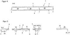
- FIG. 4 shows the section BB FIG. 2 , Visible in the middle section M a total of three hollow chambers.
- the walls on the upper side O and the underside U of the reinforcement strut 1 are flat or planar and connected to one another by the inner walls 2 and the outer walls 3 ,
- the flat flange 20 is formed only by the outer wall 3, which at the same time limits the main hollow chamber 10 of the reinforcing strut 1 to the outside. Only in the direction of the end regions 15, 25 is the flat flange 20 made larger or widening and extends at an angle to the main longitudinal axis 13. Adjacent to the end-side end regions 15 of the main hollow chamber 10, the end regions 25 of the flat flange 20 are arranged.
- FIG. 5 a cross section at the level of the section AA of FIG. 2 are the end portions of the three hollow chambers 50, 30, and 10 clearly visible and also how they are trench-shaped in cross-section. It is so in the end of the hollow chambers a double layer 8 with no or only slight air gap from the upper in the image plane Wall 5 and formed in the image plane bottom wall 6 of the reinforcing strut 1, which extends between the outer walls 3 and the inner walls 2 respectively.
- the double layer 8 can be produced by an embossment on the underside 6 between the inner walls 2 of the hollow output profile, it being apparent that the hollow chambers 10, 30 and 50 in their end regions in each case in two divided by the double layer 8 sub-chambers, here for example by the reference numerals 11, 12 for the end region of the main hollow chamber 10, are divided.
- the flat flange 20 connects with a wall thickness W20, which here approximately twice the wall thickness W5 of the upper wall 5 in the region of the hollow chambers 10, 30 and 50 or the sum of Wall thickness of the upper wall 5 and the lower wall 6 corresponds.
- the first embodiment is mainly used as a tunnel reinforcement strut, which extends from a floor panel below the transmission tunnel to the opposite floor panel.
- the reinforcement strut serves to absorb energy, support, load line from the impact side to the opposite side of the vehicle and the torsional rigidity of the entire vehicle structure.
- FIG. 6 shows a second embodiment of the reinforcing strut according to the invention in a plan view.
- the reinforcement strut 1 has a further flat flange 40 in the image plane to the left of the further hollow chamber 50.
- the flat flange 20 of the first embodiment is pointing away from the main hollow chamber 10 and has from the output hollow profile starting trimmed end portions 45.
- the flat flanges 20, 40 there is essentially a structure symmetrical to the longitudinal axis of the further hollow chamber 30.
- the additional flat flange 40 after installation in the motor vehicle, provides two additional load paths or the two load paths of the flat flange 20 are extended into the two arms of the further flat flange 40.
- FIG. 7 shows the second embodiment of the reinforcing strut according to the invention in a view from below. It is a three-chamber hollow profile made of light metal.
- the main hollow chamber 10 as well as the further hollow chambers 30, 50 arranged to the left in the image plane have a length L1.
- the two flat flanges 20 and 40 each have a length L2 or L4, wherein the length L1 of the main hollow chamber 10 is at least 25 percent smaller than the length of the flat flange 20 and the length of the flat flange 40th
- the flat flange has two opposite, end-side end regions 25, wherein these end regions 25 have a collar 26 at least on one side parallel to the first longitudinal axis 23 or parallel to the second longitudinal axis 24.
- the collar 26, like the double layers 8, can be made by compression molding.
- the collar 26 is formed here only on the outside and has a length L K , which is greater than or equal to the partial length TL2 of the end portion 25. In the case of an additional collar on the opposite side of the collar 26, this collar would have a length which corresponds at most to the partial length TL2.
- the further flat flange 40 has two opposite, end-side end portions 45, said end portions 45 at least on one side a collar 26 parallel to the first longitudinal axis 43 and parallel to the second longitudinal axis 44.
- the flat flange 20 and the flat flange 40 have end-side end regions 25, 45 each having a partial length TL, wherein the partial length TL is smaller than 0.2 times the length L2 of the flat flange 20 and the length L4 of the flat flange 40.
- the partial length is the greater, the larger area or deeper in the plan view of a Be440 the output hollow profile between the front end portions 25 of the flat flange 20 and the main hollow chamber 10 was executed.
- the partial lengths TL of the end regions 25, 45 of the flat flanges 20, 40 may also differ from one another depending on the installation situation.
- FIG. 8 shows a cross section of the section BB FIG. 6 , A three-chamber profile with the main hollow chamber 10 and two further hollow chambers 30 and 50 arranged to the left thereof can be seen.
- the hollow chambers are delimited by a wall 5 on the upper side O of the reinforcing strut 1 and by a wall 6 on the underside U of the reinforcing strut.
- the hollow chambers 50, 30 and 10 are formed separately from each other.
- outer walls 3 the reinforcing strut 1 is limited to the outside.
- This cross-sectional profile is formed homogeneously over part of the middle section M. In the direction of the end regions of the reinforcing strut, however, a flat flange 20 adjoins the outer wall 3 in the image plane on the right, the width of the end regions becoming greater or greater.
- FIG. 9 shows a cross section AA FIG. 6 which extends through the end regions 15, 25, 55 of the hollow chambers 10, 30, 50 and through the end regions 25, 45 of the flat flanges 20 and 40.
- the hollow chambers in the end-side end regions for example, are trench-shaped in flattened fashion by embossing into double layers 8.
- the hollow chambers 10, 30 and 50 in their end regions in each case in two divided by the double layer 8 sub-chambers, here represented for example by the reference numerals 11, 12 for the end portion 15 of the main hollow chamber 10, are divided.
- joints 9 are provided for coupling to other vehicle components.
- the flat flanges 20 and 40 can be seen, which have a downwardly bent collar 26 in the image plane.
- the second embodiment is particularly useful as a subframe between the lower longitudinal members of the front of the vehicle.
- FIG. 10 shows a motor vehicle 100 according to the invention in a greatly simplified
- the motor vehicle 100 has a tunnel 60, which extends centrally along the vehicle longitudinal axis X and forms part of the vehicle body. Transverse to the tunnel 60, a reinforcing strut 1 according to the invention is arranged. The reinforcement strut 1 thus also extends transversely to the vehicle longitudinal axis X and, after the coupling with parts of the vehicle body, forms additional load paths via joining points 9.
Landscapes
- Engineering & Computer Science (AREA)
- Chemical & Material Sciences (AREA)
- Combustion & Propulsion (AREA)
- Transportation (AREA)
- Mechanical Engineering (AREA)
- Architecture (AREA)
- Structural Engineering (AREA)
- Body Structure For Vehicles (AREA)
Applications Claiming Priority (1)
| Application Number | Priority Date | Filing Date | Title |
|---|---|---|---|
| DE102016125335.9A DE102016125335B3 (de) | 2016-12-22 | 2016-12-22 | Verstärkungsstrebe für ein Kraftfahrzeug |
Publications (2)
| Publication Number | Publication Date |
|---|---|
| EP3348457A1 true EP3348457A1 (fr) | 2018-07-18 |
| EP3348457B1 EP3348457B1 (fr) | 2020-06-24 |
Family
ID=60191195
Family Applications (1)
| Application Number | Title | Priority Date | Filing Date |
|---|---|---|---|
| EP17198896.7A Active EP3348457B1 (fr) | 2016-12-22 | 2017-10-27 | Appui de renforcement pour un véhicule automobile |
Country Status (2)
| Country | Link |
|---|---|
| EP (1) | EP3348457B1 (fr) |
| DE (1) | DE102016125335B3 (fr) |
Cited By (1)
| Publication number | Priority date | Publication date | Assignee | Title |
|---|---|---|---|---|
| CN113002621A (zh) * | 2019-12-20 | 2021-06-22 | 德国汽车工程技术有限公司 | 用于机动车的副车架 |
Families Citing this family (2)
| Publication number | Priority date | Publication date | Assignee | Title |
|---|---|---|---|---|
| DE102018128004A1 (de) | 2018-11-08 | 2020-05-14 | Bayerische Motoren Werke Aktiengesellschaft | Achsträger eines Fahrzeugs mit einem Schubfeld |
| FR3150496B1 (fr) * | 2023-06-30 | 2025-05-16 | Psa Automobiles Sa | Ensemble de soubassement d’un véhicule automobile et véhicule automobile comportant un tel ensemble de soubassement |
Citations (7)
| Publication number | Priority date | Publication date | Assignee | Title |
|---|---|---|---|---|
| US3625561A (en) * | 1968-02-01 | 1971-12-07 | Daimler Benz Ag | Reinforcing elements for a motor vehicle body |
| US5685599A (en) * | 1995-03-03 | 1997-11-11 | Nissan Motor Co., Ltd. | Structural member of vehicle body |
| EP1577196A1 (fr) * | 2002-12-26 | 2005-09-21 | Toyota Jidosha Kabushiki Kaisha | Structure de corps avant de vehicule |
| US20050275182A1 (en) * | 2004-06-09 | 2005-12-15 | Volkswagen Aktiengesellschaft | Underride protection device for passenger vehicles for placement below longitudinal chassis beams and in front of a sub-frame or cross member as an additional crash plane |
| US20060175873A1 (en) * | 2005-02-04 | 2006-08-10 | Nissan Motor Co., Ltd. | Vehicle front body structure |
| US20060175872A1 (en) * | 2005-02-04 | 2006-08-10 | Nissan Motor Co., Ltd. | Vehicle underbody structure |
| EP1706308A1 (fr) * | 2004-01-02 | 2006-10-04 | Wilhelm Karmann GmbH | Carrosserie de vehicule dont le dessous de caisse presente des entretoises de renfort |
Family Cites Families (5)
| Publication number | Priority date | Publication date | Assignee | Title |
|---|---|---|---|---|
| NO165284C (no) * | 1988-09-09 | 1991-01-23 | Norsk Hydro As | Fremgangsmaate ved fremstilling av karosseriramme og karosserirammen. |
| DE10208778B4 (de) * | 2002-02-28 | 2004-08-12 | Thyssenkrupp Stahl Ag | Aus Stahl-Hohlprofilen gebildete Tragstruktur für Fahrzeuge |
| DE102005004780B3 (de) * | 2005-02-01 | 2006-09-07 | Dr.Ing.H.C. F. Porsche Ag | Deformationselement für ein Kraftfahrzeug |
| DE102007035510A1 (de) * | 2007-07-28 | 2009-01-29 | Bayerische Motoren Werke Aktiengesellschaft | Hilfsrahmen im Fahrwerksbereich eines zweispurigen Fahrzeugs |
| US9731768B2 (en) * | 2015-03-27 | 2017-08-15 | Ford Global Technologies, Llc | Vehicle structural reinforcing device |
-
2016
- 2016-12-22 DE DE102016125335.9A patent/DE102016125335B3/de not_active Expired - Fee Related
-
2017
- 2017-10-27 EP EP17198896.7A patent/EP3348457B1/fr active Active
Patent Citations (7)
| Publication number | Priority date | Publication date | Assignee | Title |
|---|---|---|---|---|
| US3625561A (en) * | 1968-02-01 | 1971-12-07 | Daimler Benz Ag | Reinforcing elements for a motor vehicle body |
| US5685599A (en) * | 1995-03-03 | 1997-11-11 | Nissan Motor Co., Ltd. | Structural member of vehicle body |
| EP1577196A1 (fr) * | 2002-12-26 | 2005-09-21 | Toyota Jidosha Kabushiki Kaisha | Structure de corps avant de vehicule |
| EP1706308A1 (fr) * | 2004-01-02 | 2006-10-04 | Wilhelm Karmann GmbH | Carrosserie de vehicule dont le dessous de caisse presente des entretoises de renfort |
| US20050275182A1 (en) * | 2004-06-09 | 2005-12-15 | Volkswagen Aktiengesellschaft | Underride protection device for passenger vehicles for placement below longitudinal chassis beams and in front of a sub-frame or cross member as an additional crash plane |
| US20060175873A1 (en) * | 2005-02-04 | 2006-08-10 | Nissan Motor Co., Ltd. | Vehicle front body structure |
| US20060175872A1 (en) * | 2005-02-04 | 2006-08-10 | Nissan Motor Co., Ltd. | Vehicle underbody structure |
Cited By (2)
| Publication number | Priority date | Publication date | Assignee | Title |
|---|---|---|---|---|
| CN113002621A (zh) * | 2019-12-20 | 2021-06-22 | 德国汽车工程技术有限公司 | 用于机动车的副车架 |
| CN113002621B (zh) * | 2019-12-20 | 2023-03-28 | 德国汽车工程技术有限公司 | 用于机动车的副车架 |
Also Published As
| Publication number | Publication date |
|---|---|
| DE102016125335B3 (de) | 2017-12-28 |
| EP3348457B1 (fr) | 2020-06-24 |
Similar Documents
| Publication | Publication Date | Title |
|---|---|---|
| EP2976250B1 (fr) | Seuil de porte pour une carrosserie de véhicule | |
| EP1036715B1 (fr) | Ensemble pare-chocs | |
| EP2782811B1 (fr) | Élément de carosserie de construction légère | |
| DE60013761T2 (de) | Fahrzeugrahmen | |
| EP1840003B1 (fr) | Elément de renforcement d'un soubassement de porte de carrosserie de véhicule automobile | |
| DE10003878B4 (de) | Zusatzelement | |
| DE102011051481B4 (de) | Stoßfängeranordnung für ein Kraftfahrzeug | |
| EP1083098B1 (fr) | Amortisseur de choc pour véhicule | |
| DE102010020304A1 (de) | Hilfsträger | |
| WO2009121509A1 (fr) | Traverse pour un pare-chocs d'un véhicule automobile et procédé de fabrication d'une traverse. | |
| DE102011117682A1 (de) | Längsrahmen für die Unterbaustruktur eines Kraftfahrzeuges und Kraftfahrzeug-Unterbaustruktur | |
| EP3007958B1 (fr) | Support d'essieu d'un véhicule comportant un élément de renforcement en matériau composite renforcé par des fibres | |
| EP3348457B1 (fr) | Appui de renforcement pour un véhicule automobile | |
| EP2030869B1 (fr) | Support en tant que traverse ou longeron dans un véhicule automobile | |
| DE102013209095A1 (de) | Crashstruktur für ein Fahrzeug | |
| EP1914096A1 (fr) | Entretoise transversale pour la carrosserie d'un véhicule automobile | |
| DE102006041092A1 (de) | Knautschzone einer Karosserie eines Kraftwagens | |
| DE102004010792A1 (de) | Schutzvorrichtung für Kraftfahrzeuge | |
| EP2617629B1 (fr) | Noeud de carrosserie | |
| DE102019217259B4 (de) | Kraftfahrzeugkarosserie und Schwellerbaugruppe | |
| DE102015118810B4 (de) | Verstärkungsstrebe für ein Kraftfahrzeug | |
| DE202014004746U1 (de) | Verstärkungsmittel, Rahmenstruktur und Kraftfahrzeug | |
| EP1277621B1 (fr) | Pare-chocs pour véhicule automobile | |
| EP2501589B1 (fr) | Protection anti-encastrement pour vehicules utilitaires | |
| DE102006015414B4 (de) | Trägerhohlprofil für ein Kraftfahrzeug |
Legal Events
| Date | Code | Title | Description |
|---|---|---|---|
| PUAI | Public reference made under article 153(3) epc to a published international application that has entered the european phase |
Free format text: ORIGINAL CODE: 0009012 |
|
| STAA | Information on the status of an ep patent application or granted ep patent |
Free format text: STATUS: THE APPLICATION HAS BEEN PUBLISHED |
|
| AK | Designated contracting states |
Kind code of ref document: A1 Designated state(s): AL AT BE BG CH CY CZ DE DK EE ES FI FR GB GR HR HU IE IS IT LI LT LU LV MC MK MT NL NO PL PT RO RS SE SI SK SM TR |
|
| AX | Request for extension of the european patent |
Extension state: BA ME |
|
| STAA | Information on the status of an ep patent application or granted ep patent |
Free format text: STATUS: REQUEST FOR EXAMINATION WAS MADE |
|
| 17P | Request for examination filed |
Effective date: 20190116 |
|
| RBV | Designated contracting states (corrected) |
Designated state(s): AL AT BE BG CH CY CZ DE DK EE ES FI FR GB GR HR HU IE IS IT LI LT LU LV MC MK MT NL NO PL PT RO RS SE SI SK SM TR |
|
| RIN1 | Information on inventor provided before grant (corrected) |
Inventor name: MARCUSSEN, POVL ERIK Inventor name: MAERZ, WALTER |
|
| RAP1 | Party data changed (applicant data changed or rights of an application transferred) |
Owner name: BENTELER AUTOMOBILTECHNIK GMBH Owner name: AUDI AG |
|
| GRAP | Despatch of communication of intention to grant a patent |
Free format text: ORIGINAL CODE: EPIDOSNIGR1 |
|
| STAA | Information on the status of an ep patent application or granted ep patent |
Free format text: STATUS: GRANT OF PATENT IS INTENDED |
|
| INTG | Intention to grant announced |
Effective date: 20200113 |
|
| GRAS | Grant fee paid |
Free format text: ORIGINAL CODE: EPIDOSNIGR3 |
|
| GRAA | (expected) grant |
Free format text: ORIGINAL CODE: 0009210 |
|
| STAA | Information on the status of an ep patent application or granted ep patent |
Free format text: STATUS: THE PATENT HAS BEEN GRANTED |
|
| AK | Designated contracting states |
Kind code of ref document: B1 Designated state(s): AL AT BE BG CH CY CZ DE DK EE ES FI FR GB GR HR HU IE IS IT LI LT LU LV MC MK MT NL NO PL PT RO RS SE SI SK SM TR |
|
| REG | Reference to a national code |
Ref country code: GB Ref legal event code: FG4D Free format text: NOT ENGLISH |
|
| REG | Reference to a national code |
Ref country code: CH Ref legal event code: EP |
|
| REG | Reference to a national code |
Ref country code: DE Ref legal event code: R096 Ref document number: 502017005834 Country of ref document: DE |
|
| REG | Reference to a national code |
Ref country code: AT Ref legal event code: REF Ref document number: 1283617 Country of ref document: AT Kind code of ref document: T Effective date: 20200715 |
|
| REG | Reference to a national code |
Ref country code: IE Ref legal event code: FG4D Free format text: LANGUAGE OF EP DOCUMENT: GERMAN |
|
| PG25 | Lapsed in a contracting state [announced via postgrant information from national office to epo] |
Ref country code: NO Free format text: LAPSE BECAUSE OF FAILURE TO SUBMIT A TRANSLATION OF THE DESCRIPTION OR TO PAY THE FEE WITHIN THE PRESCRIBED TIME-LIMIT Effective date: 20200924 Ref country code: GR Free format text: LAPSE BECAUSE OF FAILURE TO SUBMIT A TRANSLATION OF THE DESCRIPTION OR TO PAY THE FEE WITHIN THE PRESCRIBED TIME-LIMIT Effective date: 20200925 Ref country code: LT Free format text: LAPSE BECAUSE OF FAILURE TO SUBMIT A TRANSLATION OF THE DESCRIPTION OR TO PAY THE FEE WITHIN THE PRESCRIBED TIME-LIMIT Effective date: 20200624 Ref country code: SE Free format text: LAPSE BECAUSE OF FAILURE TO SUBMIT A TRANSLATION OF THE DESCRIPTION OR TO PAY THE FEE WITHIN THE PRESCRIBED TIME-LIMIT Effective date: 20200624 Ref country code: FI Free format text: LAPSE BECAUSE OF FAILURE TO SUBMIT A TRANSLATION OF THE DESCRIPTION OR TO PAY THE FEE WITHIN THE PRESCRIBED TIME-LIMIT Effective date: 20200624 |
|
| REG | Reference to a national code |
Ref country code: LT Ref legal event code: MG4D |
|
| PG25 | Lapsed in a contracting state [announced via postgrant information from national office to epo] |
Ref country code: HR Free format text: LAPSE BECAUSE OF FAILURE TO SUBMIT A TRANSLATION OF THE DESCRIPTION OR TO PAY THE FEE WITHIN THE PRESCRIBED TIME-LIMIT Effective date: 20200624 Ref country code: LV Free format text: LAPSE BECAUSE OF FAILURE TO SUBMIT A TRANSLATION OF THE DESCRIPTION OR TO PAY THE FEE WITHIN THE PRESCRIBED TIME-LIMIT Effective date: 20200624 Ref country code: BG Free format text: LAPSE BECAUSE OF FAILURE TO SUBMIT A TRANSLATION OF THE DESCRIPTION OR TO PAY THE FEE WITHIN THE PRESCRIBED TIME-LIMIT Effective date: 20200924 Ref country code: RS Free format text: LAPSE BECAUSE OF FAILURE TO SUBMIT A TRANSLATION OF THE DESCRIPTION OR TO PAY THE FEE WITHIN THE PRESCRIBED TIME-LIMIT Effective date: 20200624 |
|
| REG | Reference to a national code |
Ref country code: NL Ref legal event code: MP Effective date: 20200624 |
|
| PG25 | Lapsed in a contracting state [announced via postgrant information from national office to epo] |
Ref country code: AL Free format text: LAPSE BECAUSE OF FAILURE TO SUBMIT A TRANSLATION OF THE DESCRIPTION OR TO PAY THE FEE WITHIN THE PRESCRIBED TIME-LIMIT Effective date: 20200624 Ref country code: NL Free format text: LAPSE BECAUSE OF FAILURE TO SUBMIT A TRANSLATION OF THE DESCRIPTION OR TO PAY THE FEE WITHIN THE PRESCRIBED TIME-LIMIT Effective date: 20200624 |
|
| PG25 | Lapsed in a contracting state [announced via postgrant information from national office to epo] |
Ref country code: PT Free format text: LAPSE BECAUSE OF FAILURE TO SUBMIT A TRANSLATION OF THE DESCRIPTION OR TO PAY THE FEE WITHIN THE PRESCRIBED TIME-LIMIT Effective date: 20201026 Ref country code: RO Free format text: LAPSE BECAUSE OF FAILURE TO SUBMIT A TRANSLATION OF THE DESCRIPTION OR TO PAY THE FEE WITHIN THE PRESCRIBED TIME-LIMIT Effective date: 20200624 Ref country code: CZ Free format text: LAPSE BECAUSE OF FAILURE TO SUBMIT A TRANSLATION OF THE DESCRIPTION OR TO PAY THE FEE WITHIN THE PRESCRIBED TIME-LIMIT Effective date: 20200624 Ref country code: ES Free format text: LAPSE BECAUSE OF FAILURE TO SUBMIT A TRANSLATION OF THE DESCRIPTION OR TO PAY THE FEE WITHIN THE PRESCRIBED TIME-LIMIT Effective date: 20200624 Ref country code: SM Free format text: LAPSE BECAUSE OF FAILURE TO SUBMIT A TRANSLATION OF THE DESCRIPTION OR TO PAY THE FEE WITHIN THE PRESCRIBED TIME-LIMIT Effective date: 20200624 Ref country code: EE Free format text: LAPSE BECAUSE OF FAILURE TO SUBMIT A TRANSLATION OF THE DESCRIPTION OR TO PAY THE FEE WITHIN THE PRESCRIBED TIME-LIMIT Effective date: 20200624 Ref country code: IT Free format text: LAPSE BECAUSE OF FAILURE TO SUBMIT A TRANSLATION OF THE DESCRIPTION OR TO PAY THE FEE WITHIN THE PRESCRIBED TIME-LIMIT Effective date: 20200624 |
|
| PG25 | Lapsed in a contracting state [announced via postgrant information from national office to epo] |
Ref country code: SK Free format text: LAPSE BECAUSE OF FAILURE TO SUBMIT A TRANSLATION OF THE DESCRIPTION OR TO PAY THE FEE WITHIN THE PRESCRIBED TIME-LIMIT Effective date: 20200624 Ref country code: PL Free format text: LAPSE BECAUSE OF FAILURE TO SUBMIT A TRANSLATION OF THE DESCRIPTION OR TO PAY THE FEE WITHIN THE PRESCRIBED TIME-LIMIT Effective date: 20200624 Ref country code: IS Free format text: LAPSE BECAUSE OF FAILURE TO SUBMIT A TRANSLATION OF THE DESCRIPTION OR TO PAY THE FEE WITHIN THE PRESCRIBED TIME-LIMIT Effective date: 20201024 |
|
| REG | Reference to a national code |
Ref country code: DE Ref legal event code: R097 Ref document number: 502017005834 Country of ref document: DE |
|
| PG25 | Lapsed in a contracting state [announced via postgrant information from national office to epo] |
Ref country code: DK Free format text: LAPSE BECAUSE OF FAILURE TO SUBMIT A TRANSLATION OF THE DESCRIPTION OR TO PAY THE FEE WITHIN THE PRESCRIBED TIME-LIMIT Effective date: 20200624 |
|
| PLBE | No opposition filed within time limit |
Free format text: ORIGINAL CODE: 0009261 |
|
| STAA | Information on the status of an ep patent application or granted ep patent |
Free format text: STATUS: NO OPPOSITION FILED WITHIN TIME LIMIT |
|
| REG | Reference to a national code |
Ref country code: CH Ref legal event code: PL |
|
| 26N | No opposition filed |
Effective date: 20210325 |
|
| PG25 | Lapsed in a contracting state [announced via postgrant information from national office to epo] |
Ref country code: MC Free format text: LAPSE BECAUSE OF FAILURE TO SUBMIT A TRANSLATION OF THE DESCRIPTION OR TO PAY THE FEE WITHIN THE PRESCRIBED TIME-LIMIT Effective date: 20200624 Ref country code: LU Free format text: LAPSE BECAUSE OF NON-PAYMENT OF DUE FEES Effective date: 20201027 |
|
| REG | Reference to a national code |
Ref country code: BE Ref legal event code: MM Effective date: 20201031 |
|
| PG25 | Lapsed in a contracting state [announced via postgrant information from national office to epo] |
Ref country code: CH Free format text: LAPSE BECAUSE OF NON-PAYMENT OF DUE FEES Effective date: 20201031 Ref country code: BE Free format text: LAPSE BECAUSE OF NON-PAYMENT OF DUE FEES Effective date: 20201031 Ref country code: SI Free format text: LAPSE BECAUSE OF FAILURE TO SUBMIT A TRANSLATION OF THE DESCRIPTION OR TO PAY THE FEE WITHIN THE PRESCRIBED TIME-LIMIT Effective date: 20200624 Ref country code: LI Free format text: LAPSE BECAUSE OF NON-PAYMENT OF DUE FEES Effective date: 20201031 |
|
| PG25 | Lapsed in a contracting state [announced via postgrant information from national office to epo] |
Ref country code: IE Free format text: LAPSE BECAUSE OF NON-PAYMENT OF DUE FEES Effective date: 20201027 |
|
| PG25 | Lapsed in a contracting state [announced via postgrant information from national office to epo] |
Ref country code: TR Free format text: LAPSE BECAUSE OF FAILURE TO SUBMIT A TRANSLATION OF THE DESCRIPTION OR TO PAY THE FEE WITHIN THE PRESCRIBED TIME-LIMIT Effective date: 20200624 Ref country code: MT Free format text: LAPSE BECAUSE OF FAILURE TO SUBMIT A TRANSLATION OF THE DESCRIPTION OR TO PAY THE FEE WITHIN THE PRESCRIBED TIME-LIMIT Effective date: 20200624 Ref country code: CY Free format text: LAPSE BECAUSE OF FAILURE TO SUBMIT A TRANSLATION OF THE DESCRIPTION OR TO PAY THE FEE WITHIN THE PRESCRIBED TIME-LIMIT Effective date: 20200624 |
|
| PG25 | Lapsed in a contracting state [announced via postgrant information from national office to epo] |
Ref country code: MK Free format text: LAPSE BECAUSE OF FAILURE TO SUBMIT A TRANSLATION OF THE DESCRIPTION OR TO PAY THE FEE WITHIN THE PRESCRIBED TIME-LIMIT Effective date: 20200624 |
|
| REG | Reference to a national code |
Ref country code: DE Ref legal event code: R082 Ref document number: 502017005834 Country of ref document: DE Representative=s name: SPRENGER, GERRIT, DIPL.-PHYS. DR.RER.NAT., DE Ref country code: DE Ref legal event code: R082 Ref document number: 502017005834 Country of ref document: DE Representative=s name: BOCKERMANN KSOLL GRIEPENSTROH OSTERHOFF, DE |
|
| P01 | Opt-out of the competence of the unified patent court (upc) registered |
Effective date: 20230530 |
|
| REG | Reference to a national code |
Ref country code: AT Ref legal event code: MM01 Ref document number: 1283617 Country of ref document: AT Kind code of ref document: T Effective date: 20221027 |
|
| PG25 | Lapsed in a contracting state [announced via postgrant information from national office to epo] |
Ref country code: AT Free format text: LAPSE BECAUSE OF NON-PAYMENT OF DUE FEES Effective date: 20221027 |
|
| REG | Reference to a national code |
Ref country code: DE Ref legal event code: R082 Ref document number: 502017005834 Country of ref document: DE Representative=s name: BOCKERMANN KSOLL GRIEPENSTROH OSTERHOFF, DE |
|
| PGFP | Annual fee paid to national office [announced via postgrant information from national office to epo] |
Ref country code: DE Payment date: 20251029 Year of fee payment: 9 |
|
| PGFP | Annual fee paid to national office [announced via postgrant information from national office to epo] |
Ref country code: GB Payment date: 20251022 Year of fee payment: 9 |
|
| PGFP | Annual fee paid to national office [announced via postgrant information from national office to epo] |
Ref country code: FR Payment date: 20251030 Year of fee payment: 9 |