EP3348509A1 - Sicherheitsvorrichtung, aufzugsystem und verfahren zur steuerung des aufzugsystems - Google Patents
Sicherheitsvorrichtung, aufzugsystem und verfahren zur steuerung des aufzugsystems Download PDFInfo
- Publication number
- EP3348509A1 EP3348509A1 EP17187527.1A EP17187527A EP3348509A1 EP 3348509 A1 EP3348509 A1 EP 3348509A1 EP 17187527 A EP17187527 A EP 17187527A EP 3348509 A1 EP3348509 A1 EP 3348509A1
- Authority
- EP
- European Patent Office
- Prior art keywords
- engagement part
- guide rail
- spacing
- guiding face
- sensor
- Prior art date
- Legal status (The legal status is an assumption and is not a legal conclusion. Google has not performed a legal analysis and makes no representation as to the accuracy of the status listed.)
- Withdrawn
Links
- 238000000034 method Methods 0.000 title claims abstract description 12
- 238000012423 maintenance Methods 0.000 claims description 19
- 238000004891 communication Methods 0.000 claims description 16
- 238000009434 installation Methods 0.000 claims description 8
- 230000007257 malfunction Effects 0.000 claims description 6
- 230000001939 inductive effect Effects 0.000 claims description 4
- 230000002265 prevention Effects 0.000 claims description 3
- 230000001419 dependent effect Effects 0.000 claims 1
- 229910000831 Steel Inorganic materials 0.000 description 2
- 239000010959 steel Substances 0.000 description 2
- 239000011247 coating layer Substances 0.000 description 1
- 238000010276 construction Methods 0.000 description 1
- 238000013461 design Methods 0.000 description 1
- 239000000428 dust Substances 0.000 description 1
- 238000011031 large-scale manufacturing process Methods 0.000 description 1
- 238000012986 modification Methods 0.000 description 1
- 230000004048 modification Effects 0.000 description 1
- 238000012544 monitoring process Methods 0.000 description 1
- 238000006467 substitution reaction Methods 0.000 description 1
- 239000000725 suspension Substances 0.000 description 1
- 230000001960 triggered effect Effects 0.000 description 1
Images


Classifications
-
- B—PERFORMING OPERATIONS; TRANSPORTING
- B66—HOISTING; LIFTING; HAULING
- B66B—ELEVATORS; ESCALATORS OR MOVING WALKWAYS
- B66B5/00—Applications of checking, fault-correcting, or safety devices in elevators
- B66B5/0087—Devices facilitating maintenance, repair or inspection tasks
- B66B5/0093—Testing of safety devices
-
- B—PERFORMING OPERATIONS; TRANSPORTING
- B66—HOISTING; LIFTING; HAULING
- B66B—ELEVATORS; ESCALATORS OR MOVING WALKWAYS
- B66B5/00—Applications of checking, fault-correcting, or safety devices in elevators
- B66B5/0006—Monitoring devices or performance analysers
- B66B5/0018—Devices monitoring the operating condition of the elevator system
- B66B5/0025—Devices monitoring the operating condition of the elevator system for maintenance or repair
-
- B—PERFORMING OPERATIONS; TRANSPORTING
- B66—HOISTING; LIFTING; HAULING
- B66B—ELEVATORS; ESCALATORS OR MOVING WALKWAYS
- B66B5/00—Applications of checking, fault-correcting, or safety devices in elevators
- B66B5/0006—Monitoring devices or performance analysers
- B66B5/0018—Devices monitoring the operating condition of the elevator system
- B66B5/0031—Devices monitoring the operating condition of the elevator system for safety reasons
-
- B—PERFORMING OPERATIONS; TRANSPORTING
- B66—HOISTING; LIFTING; HAULING
- B66B—ELEVATORS; ESCALATORS OR MOVING WALKWAYS
- B66B5/00—Applications of checking, fault-correcting, or safety devices in elevators
- B66B5/02—Applications of checking, fault-correcting, or safety devices in elevators responsive to abnormal operating conditions
-
- B—PERFORMING OPERATIONS; TRANSPORTING
- B66—HOISTING; LIFTING; HAULING
- B66B—ELEVATORS; ESCALATORS OR MOVING WALKWAYS
- B66B7/00—Other common features of elevators
- B66B7/02—Guideways; Guides
-
- B—PERFORMING OPERATIONS; TRANSPORTING
- B66—HOISTING; LIFTING; HAULING
- B66B—ELEVATORS; ESCALATORS OR MOVING WALKWAYS
- B66B2201/00—Aspects of control systems of elevators
Definitions
- the present invention relates to the field of elevators, and more particularly, to a safety device, an elevator system and a control method for controlling the elevator system.
- An elevator is a passenger vehicle commonly used in daily life and work. According to the national standard, the elevator must be provided with a safety device (commonly known as a safety gear) that provides effective protection for the safe operation of the elevator.
- the safety device is generally installed on a car frame. Under the control of a speed governor, the safety device is able to stop and hold a car on a guide rail emergently when the speed of the elevator exceeds a speed limit set by the speed governor or when a suspension rope is broken and relaxed.
- the existing safety device is usually triggered by a pulling device.
- the safety device does not trigger an action monitoring switch of the safety device because a pulling rod in some of the pulling devices is flexible, and therefore the machine cannot stop, causing a hoisting rope or a hoisting steel belt to be severely worn, especially a coating layer for the hoisting steel belt to be overworn, or even completely scrapped in severe cases.
- the malfunction of the safety device will cause passengers to be trapped in the elevator car.
- An object of the present invention is to provide a safety device which can measure the spacing between the engagement parts and the guide rail in real time.
- a further object of the present invention is to provide an elevator system having a safety device according to the present invention, and a control method for controlling the elevator system.
- the present invention provides the following technical solutions.
- a safety device installed on a car frame of an elevator, and comprising a housing, an elastic element for providing a clamping force, and an engagement member adjacent to two sides of a guide rail, wherein the engagement member is provided with a sensor for measuring a spacing between the engagement member and a guiding face of the guide rail.
- an elevator system comprising the aforementioned safety device.
- a control method for controlling an elevator system comprising a controller and the aforementioned safety device, a first step of receiving the spacing between the first engagement part and the guiding face of the guide rail from the sensor, a second step of calculating the spacing between the second engagement part and the guiding face of the guide rail based on the value of the spacing between the first engagement part and the guiding face of the guide rail, a third step of recording the value of the spacing between the first engagement part and the guiding face of the guide rail and the value of the spacing between the second engagement part and the guiding face of the guide rail, and a fourth step of comparing the spacing between the first engagement part and the guiding face of the guide rail and/or the spacing between the second engagement part and the guiding face of the guide rail with a set threshold; and if the spacing between the first engagement part and the guiding face of the guide rail and/or the spacing between the second engagement part and the guiding face of the guide rail is less than the set threshold, issuing a command to notify
- a safety device installed on a car frame of an elevator, and comprising a housing, an elastic element for providing a clamping force, and a paired first engagement part and second engagement part adjacent to two sides of a guide rail, wherein a first sensor is provided on the first engagement part for measuring a spacing between the first engagement part and a guiding face of the guide rail, and a second sensor is provided on the second engagement part for measuring a spacing between the second engagement part and the guiding face of the guide rail.
- an elevator system comprising the aforementioned safety device.
- a control method for controlling an elevator system comprising a controller and the aforementioned safety device, a first step of receiving the spacing between the first engagement part and the guiding face of the guide from the first sensor and the spacing between the second engagement part and the guiding face of the guide from the second sensor, a second step of recording the value of the spacing between the first engagement part and the guiding face of the guide rail and the value of the spacing between the second engagement part and the guiding face of the guide rail, and a third step of comparing the spacing between the first engagement part and the guiding face of the guide rail and/or the spacing between the second engagement part and the guiding face of the guide rail with a set threshold; and if the spacing between the first engagement part and the guiding face of the guide rail and/or the spacing between the second engagement part and the guiding face of the guide rail is less than the set threshold, issuing a command to notify the overhaul; otherwise, returning to the second step.
- orientation phases such as “up”, “down”, “left”, “right”, “front”, “rear”, “inside”, “outside”, “top”, “bottom” or the like mentioned or may be mentioned in the description are defined relative to the constructions shown in the various accompanying drawings, are relative concepts, and therefore may accordingly be varied according to their different locations and different usage stages. Therefore, these or other orientation phases should not be construed as limiting either.
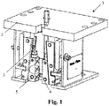
- the safety device 1 may be installed on a car frame of an elevator and is linked to a pulling device (not shown) located on the car frame of the elevator. It can be seen from the embodiment shown in Figs. 1 and 2 , the safety device 1 includes a housing 2, an elastic element 3, and an engagement member adjacent to two sides of a guide rail 4.
- the engagement member herein may be designed to be, for example, a paired first engagement part 5 and second engagement part 6 which are located adjacent to the two sides of the guide rail 4 and are preferably designed as wedges or rollers.
- the elastic element 3 may be configured, for example, as a spring to provide a clamping force of the safety device 1.
- the first engagement part 5 and the second engagement part 6 may be both installed inside the housing 2 and connected to a pulling device via a pulling rod. Further, the first engagement part 5 and the second engagement part 6 are provided with a pattern on the side close to the guiding face of the guide rail 4 in order to increase the frictional force at the time of engagement. It is contemplated that a sensor is provided on the first engagement part 5 or the second engagement part 6 for accurately measuring a spacing G1 between the first engagement part 5 and the guiding face of the guide rail 4 in real time.
- the senor may preferably be designed as an inductive proximity sensor, which is highly reliable and capable of maintaining a high-precision operation in a dusty and/or oily environment.
- the specific structure of the sensor is not drawn in Fig. 1 , with only a circle indicating the approximate position of the sensor. It should be noted that the sensor is installed in such a position as to avoid or withstand the great friction force and heat generated by the first engagement part 5 and the guiding face of the guide rail 4 when the safety device 1 is actuated.
- the sensor is preferably provided at the bottom of the first engagement part 5 or the second engagement part 6.
- the present invention further provides an elevator system, which utilizes the safety devices described above, the elevator system comprising a controller comprising: a first distance determination module in communication with the sensor; a second distance determination module in communication with the first distance determination module for determining a spacing G2 between the guiding face of the guide rail 4 and the second engagement part 6; a comparison module in communication with the first distance determination module and the second distance determination module for comparing the spacing G1 between the first engagement part 5 and the guiding face of the guide rail 4 and the spacing G2 between the second engagement part 6 and the guiding face of the guide rail 4 with a set threshold; and a control module in communication with the comparison module.
- a controller comprising: a first distance determination module in communication with the sensor; a second distance determination module in communication with the first distance determination module for determining a spacing G2 between the guiding face of the guide rail 4 and the second engagement part 6; a comparison module in communication with the first distance determination module and the second distance determination module for comparing the spacing G1 between the first engagement part 5 and the guiding
- the elevator system comprises an installation and commissioning mode, a maintenance mode and a normal operation mode.
- the response logic of these modes are respectively described below as follows:
- the control module issues a command to record the value of the spacing between the first engagement part and the guiding face of the guide rail and the value of the spacing between the second engagement part and the guiding face of the guide rail. Further, as a result of the comparison by the comparison module, if the spacing G1 between the first engagement part 5 and the guiding face of the guide rail 4 or the spacing G2 between the second engagement part 6 and the guiding face of the guide rail 4 is less than the set threshold, the control module issues a command to notify the maintenance staff to perform overhaul.
- control module further comprises a malfunction prevention checking unit for detecting whether the number of consecutive points where the measured value of the spacing is less than the set threshold is within a pre-set range of number of points, thereby effectively excluding singular points affected by the oil, dust and other accidental factors.
- the method of controlling the elevator system of the present invention comprises the following steps:
- a first sensor is provided on the first engagement part 5 for accurately measuring the spacing G1 between the first engagement part 5 and the guiding face of the guide rail 4 in real time
- a second sensor is further provided on the second engagement part 6 for accurately measuring the spacing G2 between the second engagement engagement 6 and the guiding face of the guide rail 4 in real time.
- the elevator system can monitor the spacing G1 between the first engagement part 5 and the guiding face of the guide rail 4 and/or the spacing G2 between the second engagement part 6 and the guiding face of the guide rail 4 in real time, such that the measured result is more accurate.
- the preferred structural design of the safety device 1 itself can be referred to the aforementioned embodiment and therefore will not be described again for the sake of brevity.
- the first sensor is located at the bottom of the first engagement part 5 and the second sensor is located at the bottom of the second engagement part 6.
- the first sensor and the second sensor are inductive proximity sensors.
- the first sensor and the second sensor are installed at the same height.
- the present invention further provides an elevator system provided with the aforementioned safety device. Due to the arrangement of the second sensor, the elevator system in this embodiment is primarily distinguished from the previously mentioned elevator system in the second distance determination module, which may be arranged to be in direct communication with the second sensor.
- the method of controlling the elevator system of the present invention comprises the following steps:
- the safety device of the present invention advantageously reduces the labour and time for adjusting the operating distance between the engagement parts and the guiding face of the guide rail and can immediately read the measured values of the spacings, so as to confirm in real time whether the elevator is in a safe operation state.
- This function is especially useful for high-speed elevators.
- the safety device reduces the maintenance cost of the traction rope failed prematurely due to the incorrect engagement of the safety gear. Since the safety device has many advantages in terms of the overall structure and detail structure, it is very suitable for large-scale production and application as a universal component installed on the elevator.
Landscapes
- Maintenance And Inspection Apparatuses For Elevators (AREA)
Applications Claiming Priority (1)
| Application Number | Priority Date | Filing Date | Title |
|---|---|---|---|
| CN201610710369.0A CN107777496A (zh) | 2016-08-24 | 2016-08-24 | 安全装置、电梯系统以及对电梯系统进行控制的控制方法 |
Publications (1)
| Publication Number | Publication Date |
|---|---|
| EP3348509A1 true EP3348509A1 (de) | 2018-07-18 |
Family
ID=59686877
Family Applications (1)
| Application Number | Title | Priority Date | Filing Date |
|---|---|---|---|
| EP17187527.1A Withdrawn EP3348509A1 (de) | 2016-08-24 | 2017-08-23 | Sicherheitsvorrichtung, aufzugsystem und verfahren zur steuerung des aufzugsystems |
Country Status (3)
| Country | Link |
|---|---|
| US (1) | US20180057310A1 (de) |
| EP (1) | EP3348509A1 (de) |
| CN (1) | CN107777496A (de) |
Families Citing this family (3)
| Publication number | Priority date | Publication date | Assignee | Title |
|---|---|---|---|---|
| CN111824882B (zh) * | 2019-04-15 | 2024-05-24 | 杭州沪宁电梯部件股份有限公司 | 一种基于轿厢安全的系统 |
| JP7507069B2 (ja) | 2020-11-19 | 2024-06-27 | 株式会社日立製作所 | 非常止め装置の調整治具及び非常止め装置 |
| CN112607551B (zh) * | 2020-12-30 | 2024-09-27 | 菱王电梯有限公司 | 一种电梯安全钳试验装置、其试验方法及其实训考核方法 |
Citations (3)
| Publication number | Priority date | Publication date | Assignee | Title |
|---|---|---|---|---|
| US5159995A (en) * | 1989-12-18 | 1992-11-03 | Kone Elevator Gmbh | Safety gear for an elevator |
| EP1749780A1 (de) * | 2004-05-28 | 2007-02-07 | Mitsubishi Denki Kabushiki Kaisha | Aufzugsseilschlupfdetektor und aufzugssystem |
| US20160137455A1 (en) * | 2013-06-21 | 2016-05-19 | Inventio Ag | Elevator brake force and distance sensor |
-
2016
- 2016-08-24 CN CN201610710369.0A patent/CN107777496A/zh active Pending
-
2017
- 2017-08-23 US US15/684,036 patent/US20180057310A1/en not_active Abandoned
- 2017-08-23 EP EP17187527.1A patent/EP3348509A1/de not_active Withdrawn
Patent Citations (3)
| Publication number | Priority date | Publication date | Assignee | Title |
|---|---|---|---|---|
| US5159995A (en) * | 1989-12-18 | 1992-11-03 | Kone Elevator Gmbh | Safety gear for an elevator |
| EP1749780A1 (de) * | 2004-05-28 | 2007-02-07 | Mitsubishi Denki Kabushiki Kaisha | Aufzugsseilschlupfdetektor und aufzugssystem |
| US20160137455A1 (en) * | 2013-06-21 | 2016-05-19 | Inventio Ag | Elevator brake force and distance sensor |
Also Published As
| Publication number | Publication date |
|---|---|
| US20180057310A1 (en) | 2018-03-01 |
| CN107777496A (zh) | 2018-03-09 |
Similar Documents
| Publication | Publication Date | Title |
|---|---|---|
| JP6317077B2 (ja) | エレベーターの安全システム | |
| JP4468224B2 (ja) | エレベータの位置検出システム及び方法 | |
| CN100415625C (zh) | 用于监视电梯安全的方法和电梯设备的安全监视系统 | |
| CN109896392B (zh) | 电梯系统的轨道和乘坐质量的连续监控 | |
| CN102530671B (zh) | 电梯系统 | |
| EP3127853B1 (de) | Überwachungssystem, aufzugstürsystem mit dem überwachungssystem und verfahren | |
| US20130118836A1 (en) | Elevator with safety device | |
| CN101891092B (zh) | 电梯设备 | |
| US11242220B2 (en) | Safety braking systems for elevators | |
| EP3225578A1 (de) | Zustandserfassungsanordnung für die bremsanlage eines aufzugssystems und verfahren | |
| CN110921449B (zh) | 电梯系统的基于传感器的停机检测 | |
| BR112017025853B1 (pt) | Dispositivo de monitoramento para um sistema de elevador, processo para monitoramento de um parâmetro de funcionamento de um sistema de elevador e sistema de elevador | |
| EP3348509A1 (de) | Sicherheitsvorrichtung, aufzugsystem und verfahren zur steuerung des aufzugsystems | |
| CN104718148A (zh) | 电梯设备的安全装置 | |
| EP2765109A2 (de) | Steuersystem für Position, Geschwindigkeitsbegrenzung und unkontrollierte Bewegungen der Kabine oder des Gegengewichts eines Aufzugs | |
| CN105270956B (zh) | 电梯制动滑移量及曳引轮滑移量的监测系统及监测方法 | |
| CN202542667U (zh) | 一种自动扶梯或自动人行道安全保护装置 | |
| US20110240412A1 (en) | Elevator braking control | |
| EP3288885A1 (de) | Überwachungssystem für aufzugssystem zur sicherstellung des vorbestimmten aufzugsschachtspiels | |
| JP6749860B2 (ja) | エレべーター制御システム | |
| CN101602460A (zh) | 电梯制动装置 | |
| CN209850179U (zh) | 一种防碰撞焊接机器人地轨 | |
| CN201411297Y (zh) | 基于电子安全钳的电梯装置 | |
| JP6445644B1 (ja) | エレベータ異常検出システム、および、エレベータ異常検出方法 | |
| CN201411298Y (zh) | 电梯制动装置 |
Legal Events
| Date | Code | Title | Description |
|---|---|---|---|
| PUAI | Public reference made under article 153(3) epc to a published international application that has entered the european phase |
Free format text: ORIGINAL CODE: 0009012 |
|
| STAA | Information on the status of an ep patent application or granted ep patent |
Free format text: STATUS: THE APPLICATION HAS BEEN PUBLISHED |
|
| AK | Designated contracting states |
Kind code of ref document: A1 Designated state(s): AL AT BE BG CH CY CZ DE DK EE ES FI FR GB GR HR HU IE IS IT LI LT LU LV MC MK MT NL NO PL PT RO RS SE SI SK SM TR |
|
| AX | Request for extension of the european patent |
Extension state: BA ME |
|
| STAA | Information on the status of an ep patent application or granted ep patent |
Free format text: STATUS: THE APPLICATION IS DEEMED TO BE WITHDRAWN |
|
| 18D | Application deemed to be withdrawn |
Effective date: 20190119 |