EP3348720B1 - Vorrichtung zur abwasserführung - Google Patents
Vorrichtung zur abwasserführung Download PDFInfo
- Publication number
- EP3348720B1 EP3348720B1 EP17151321.1A EP17151321A EP3348720B1 EP 3348720 B1 EP3348720 B1 EP 3348720B1 EP 17151321 A EP17151321 A EP 17151321A EP 3348720 B1 EP3348720 B1 EP 3348720B1
- Authority
- EP
- European Patent Office
- Prior art keywords
- housing
- cover lid
- opening edge
- opening
- sealing
- Prior art date
- Legal status (The legal status is an assumption and is not a legal conclusion. Google has not performed a legal analysis and makes no representation as to the accuracy of the status listed.)
- Active
Links
Images


Classifications
-
- E—FIXED CONSTRUCTIONS
- E03—WATER SUPPLY; SEWERAGE
- E03F—SEWERS; CESSPOOLS
- E03F7/00—Other installations or implements for operating sewer systems, e.g. for preventing or indicating stoppage; Emptying cesspools
- E03F7/02—Shut-off devices
- E03F7/04—Valves for preventing return flow
-
- F—MECHANICAL ENGINEERING; LIGHTING; HEATING; WEAPONS; BLASTING
- F16—ENGINEERING ELEMENTS AND UNITS; GENERAL MEASURES FOR PRODUCING AND MAINTAINING EFFECTIVE FUNCTIONING OF MACHINES OR INSTALLATIONS; THERMAL INSULATION IN GENERAL
- F16K—VALVES; TAPS; COCKS; ACTUATING-FLOATS; DEVICES FOR VENTING OR AERATING
- F16K15/00—Check valves
- F16K15/02—Check valves with guided rigid valve members
- F16K15/03—Check valves with guided rigid valve members with a hinged closure member or with a pivoted closure member
- F16K15/035—Check valves with guided rigid valve members with a hinged closure member or with a pivoted closure member with a plurality of valve members
-
- F—MECHANICAL ENGINEERING; LIGHTING; HEATING; WEAPONS; BLASTING
- F16—ENGINEERING ELEMENTS AND UNITS; GENERAL MEASURES FOR PRODUCING AND MAINTAINING EFFECTIVE FUNCTIONING OF MACHINES OR INSTALLATIONS; THERMAL INSULATION IN GENERAL
- F16K—VALVES; TAPS; COCKS; ACTUATING-FLOATS; DEVICES FOR VENTING OR AERATING
- F16K27/00—Construction of housing; Use of materials therefor
Definitions
- the invention relates to a device of the type mentioned in the preamble of claim 1.
- Such devices in particular backflow stops, have been designed by the manufacturers in such a way that they can be installed either in free installation with an exposed cover, possibly carrying additional devices, or in so-called shaft installation.
- the cover and the additional devices are accessible from the inside of the shaft, which is installed on a shaft cup attached to the housing.
- the housing becomes dirty in these relatively large areas, some of which are undercut, after a long period of use, so that in the event of an inspection or maintenance or replacement of insert parts of the device, complex cleaning work is required before the cover is removed.
- Staufix for waste water containing faeces has already been used for shaft installation with additional structural effort, e.g. concreted in a floor slab.
- Known device can be used both in free installation and in shaft installation.
- the housing is made of polymer concrete.
- a collar-like ring flange stands high from an insulating flange of the housing, into which an attachment part, for example a manhole cup, is tightly inserted on the inside.
- the ring flange increases the overall height of the housing considerably, which is undesirable for free installation.
- the tight insertion of the attachment part does not provide a reliable sealing effect.
- the invention is based on the object of specifying a device of the type mentioned at the outset which, with increased operational reliability and a compact overall height, enables simple handling and can optionally be installed in free installation or in a shaft installation within a sewage line.
- the lid can also be easily lifted out again, since the support elements encompass the engagement elements on all sides, so that dirt or deposits hardly find access there.
- the bulge protection is housed inside the outer contour of the opening edge and at the top in the cover, the same device with compact dimensions in the vertical and transverse direction can be used not only for free installation but also optionally for shaft installation, for example with a shaft cup placed over the outer contour for a shaft construction .
- the housing in the outer contour of the opening edge for example via a narrow support edge adjacent to the opening edge and the bulge protection, has a circumferential, outwardly open sealing groove for a shaft cup -Radial seal on. If the device is installed freely, the sealing groove that is then not used does not interfere. This does not widen the housing and, above all, remains compact in the vertical direction. However, it is possible to use the sealing groove in the shaft installation to accommodate a radial seal.
- the inserted engagement element extends at least to the free end of the support element.
- there is a mutual engagement depth between the support element and the engagement element which is greater than a lifting stroke of a cover radial seal from the inspection opening.
- the bulge safeguards due to their design, form guiding devices for inserting and lifting out the cover radial seal arranged on an underside fold of the cover into and out of the inspection opening. This simplifies handling, especially when the device is installed in the shaft.
- the engaging element has an approximately rectangular full cross section, elongated in the direction of the long side of the opening edge, the length of which is a multiple of the thickness.
- the cross section of the engagement element can gradually decrease towards its free end, the inner side can be straight and the outer side can be convexly curved.
- the cross section of the insertion opening in the lid and the chimney-like support element can be rectangular.
- the convex outside of the engaging element can be chamfered or rounded towards the free end to ensure easy entry of the engaging element into the insertion opening.
- the sealing groove in the outer contour of the opening edge expediently runs in a sealing plane which is at least substantially parallel to the opening edge, as close as possible to the bottom Opening edge.
- This sealing level for the manhole cup can be at the same height as the sealing level of the lid inside the inspection opening. This avoids large-area and / or undercut exposed areas in the cover area, in which dirt could settle in a concentrated manner, even when a shaft is installed.
- the top of the lid can lie essentially flush with the bottom of the manhole in the manhole cup, so that hardly any dirt is deposited there.
- the housing has pipe connections which are parallel and offset in height, essentially parallel to the opening edge, by means of which the device can be incorporated into a sewage line.
- the concept according to the invention makes it possible for the sealing plane defined by the external sealing groove in the outer contour of the opening edge to be placed at least for the manhole cup above the pipe socket of the housing without having to accept the additional overall height of the housing there.
- a manhole cup for a manhole containing the device is mounted on the housing.
- the manhole cup is inserted with a holding collar on the outside over the outer contour of the opening edge of the housing and is sealed in the sealing plane defined by the sealing groove on the outside by means of a radial seal arranged in the sealing groove.
- Anchoring points provided on the outside of the housing enable the sealed shaft well to be securely anchored to the housing.
- the radial seal offers the advantage of swallowing relative axial movements between the housing and the shaft attachment part or of surviving without damage during assembly or disassembly.
- the housing and the lid of the device are designed in such a way that, despite the buckling protection in the lid edge area, there is as little structural height as possible or parts protruding to the outside, and yet the device can be used both for free installation and optional shaft installation.
- the 1 to 3 illustrate a device V using the non-limiting example of a backflow trap R.
- the device is optionally designed for free installation or shaft installation and is generally used for wastewater management in a wastewater line.
- the device V has a housing 1 optionally designed on the outside with ribs 17 with at least substantially coaxial, that is to say slightly vertically offset pipe sockets 2, 3 for installation in a sewage line, the pipe sockets 2, 3 possibly defining a slope that is not emphasized relative to the housing 1 can.
- a housing 1 optionally designed on the outside with ribs 17 with at least substantially coaxial, that is to say slightly vertically offset pipe sockets 2, 3 for installation in a sewage line, the pipe sockets 2, 3 possibly defining a slope that is not emphasized relative to the housing 1 can.
- the lid In the embodiment shown, the lid carries additional devices, for example a one-hand lid locking and lifting bracket 5, as well as a pivotable locking lever 6, for example for locking an in Fig. 2 shown backflow flap 14 in its closed position on a sealing seat.
- a second backflow flap 13 is indicated with its seat as a further installation part, which is removably mounted in the housing 1.
- the cover 4 could carry a pump and / or a drive motor for the lever 6 or other additional equipment, or be free of additional equipment.
- the cover 4 is inserted, for example, with a nose (not shown) into an insertion pocket in the housing 1, in the direction of the arrows marked on an opening edge 8 of the inspection opening 30, until the cover is completely seated in the inspection opening 30, and then by pressing down the Lever 5 is locked.
- a nose not shown
- the flat opening edge 8 in the embodiment shown carries two bearing blocks 33 for the bracket 5 of the cover 4, and adjacent to the bearing blocks 33 on the long sides of the housing, each an engagement element 10 in the form of a tab projecting from the opening edge 8 with a straight inside here 18 and a cambered or convexly curved outer side 19.
- the outer side 19 can be chamfered or rounded towards the free end of the engagement element 10, so that the cross section decreases towards the free end.
- Longitudinal ends 20 of the engaging element 10 are optionally seated in the support elements 11 and, as indicated at 21, can be chamfered or rounded at the top for easier insertion.
- the engaging elements 10 which have an elongated, approximately rectangular cross-section with a length that is a multiple of the thickness, inserted into the chimney-like support elements 11 which stand up from the top of the cover, each of which engages around its engaging element 10 on all sides.
- the free ends of the engaging elements 10 lie approximately at the level of the free ends of the support elements 11.
- An insertion opening 22 leads to the inside of each support element 11 in the underside of the cover 4, which is extended upwards by the chimney-like support element 11 and has, for example, an approximately rectangular cross section Has.
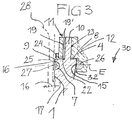
- the opening edge 8 is delimited by an outer contour 9, in which, adjacent to the opening edge 8 via a narrow supporting edge 16, an outwardly open one in one plane (sealing plane E in Fig. 3 ), circumferential sealing groove 7 is formed. It limits the opening edge 8 an inner sealing surface 15 in the housing 1, which for cooperation with an in Fig. 3
- the radial seal 26 shown is seated in an outwardly open sealing groove 32 of a fold on the lower side of the cover 4.
- Fig. 1 and 2nd further show anchoring elements 16 molded into the ribs 17 on the outside of the housing 1, here, for example, just below the outer sealing groove 7.
- a sealing collar 25 of a shaft cup 28 inserted on the outside over the outer contour 9 is indicated, on which further shaft parts ( 5 to 7 ) can be mounted, and which can be fixed in the anchoring points 16 on the housing 1 or the stiffening ribs 17, optionally (shaft installation).
- each engagement element 10 in one piece at a distance from the outer contour 9 on the opening edge 8 is integrally formed, and that each support element 11 also maintains a distance from the outer contour 9, as well as an optionally provided support edge 24 of the cover 4, so that the sealing collar 25 can be guided past it without problems.
- Fig. 1 the two support elements 11 are connected by a transverse raised stiffening rib 12 on the upper side of the cover 4 to stiffen the cover 4 and provide mutual support.
- the support element 11 defines, so to speak, a chimney-like shaft 23 for the engagement of the inserted engagement element 10.
- the embodiment of the device V in Fig. 4 also a backflow trap R, differs from that of 1 to 3 due to a possibly larger size and a further one-hand lid locking and lifting bracket 5 ', which is pivotally mounted on the lid 4 in the opposite direction to the bracket 5 and serves for an additional locking of the lid 4 in the installation position shown (one-hand operation).
- brackets 5, 5 ' are swung up and the cover 4 is lifted out with one hand on both brackets 5, 5', for example until the aforementioned insertion lug emerges from the insertion pocket in the inspection opening and the cover can be lifted up at an angle.
- the insertion nose could be omitted.
- the length of engagement between the engagement elements 10 and the support elements 11 is expediently chosen to be longer than the lifting stroke of the cover 4 when it is removed from the inspection opening 30, so that the anti-buckling devices S can additionally take over the function of a guiding device for lifting out and also for inserting the cover 4.
- Fig. 5 is a side view of the device V, for example according to 1 to 3 combined with that already in Fig. 3 indicated shaft cup 28 (a circular cup with the slip or sealing edge 25 corresponding to the outer contour 9 of the opening edge 8 of the housing 1). Since the outer sealing groove 7 is only positioned just below the opening edge 8, a secure fixing of the manhole cup 28 is still possible even above the outer contours of the pipe sockets 3, 4, and consequently the housing 1 only needs to be raised slightly above the pipe sockets 3, 4 survive. The attached manhole cup 28 is additionally fixed in the anchoring points 16.
- Fig. 7 shows as a partial sectional view and in continuation of the shaft installation principle of Fig. 5 and 6 the device V, here in turn a backflow trap R, with the shaft cup 28 fixed thereon and the built-in parts 13, 14 in a shaft 29 consisting here of several shaft elements, closed on the upper side by a grate 31. Since the shaft 29 extends over a considerable height or it is important that for an inspection or maintenance the cover 4 at the bottom of the shaft 29 can be easily removed or used with the one-handed bracket 5 or the one-handed bracket 5, 5 ', since the access conditions may be unfavorable.
Landscapes
- Engineering & Computer Science (AREA)
- General Engineering & Computer Science (AREA)
- Mechanical Engineering (AREA)
- Health & Medical Sciences (AREA)
- Life Sciences & Earth Sciences (AREA)
- Hydrology & Water Resources (AREA)
- Public Health (AREA)
- Water Supply & Treatment (AREA)
- Valve Housings (AREA)
- Sewage (AREA)
Priority Applications (5)
| Application Number | Priority Date | Filing Date | Title |
|---|---|---|---|
| RS20200882A RS60585B1 (sr) | 2017-01-13 | 2017-01-13 | Uređaj za odvođenje otpadne vode |
| EP17151321.1A EP3348720B1 (de) | 2017-01-13 | 2017-01-13 | Vorrichtung zur abwasserführung |
| PL17151321T PL3348720T3 (pl) | 2017-01-13 | 2017-01-13 | Urządzenie do prowadzenia ścieków |
| RU2017145137A RU2689481C1 (ru) | 2017-01-13 | 2017-12-21 | Устройство для канализации |
| CN201810031514.1A CN108302224B (zh) | 2017-01-13 | 2018-01-12 | 用于废水工程的装置 |
Applications Claiming Priority (1)
| Application Number | Priority Date | Filing Date | Title |
|---|---|---|---|
| EP17151321.1A EP3348720B1 (de) | 2017-01-13 | 2017-01-13 | Vorrichtung zur abwasserführung |
Publications (2)
| Publication Number | Publication Date |
|---|---|
| EP3348720A1 EP3348720A1 (de) | 2018-07-18 |
| EP3348720B1 true EP3348720B1 (de) | 2020-04-29 |
Family
ID=57799582
Family Applications (1)
| Application Number | Title | Priority Date | Filing Date |
|---|---|---|---|
| EP17151321.1A Active EP3348720B1 (de) | 2017-01-13 | 2017-01-13 | Vorrichtung zur abwasserführung |
Country Status (5)
| Country | Link |
|---|---|
| EP (1) | EP3348720B1 (pl) |
| CN (1) | CN108302224B (pl) |
| PL (1) | PL3348720T3 (pl) |
| RS (1) | RS60585B1 (pl) |
| RU (1) | RU2689481C1 (pl) |
Family Cites Families (9)
| Publication number | Priority date | Publication date | Assignee | Title |
|---|---|---|---|---|
| DE1204143B (de) * | 1960-12-05 | 1965-10-28 | Standard Elektrik Lorenz Ag | Ein- oder zweiteilige Luftabschlussklappe einer Rohrpostanlage |
| DE102005009777B4 (de) * | 2005-01-05 | 2008-08-21 | Aco Severin Ahlmann Gmbh & Co. Kg | Rückstauverschluss |
| US7325565B1 (en) * | 2005-03-23 | 2008-02-05 | Mizpah Lc | Backflow valve |
| CA2773442A1 (en) * | 2011-04-05 | 2012-10-05 | Back Water Boot Inc. | Check valve access chamber |
| CN203384428U (zh) * | 2013-03-12 | 2014-01-08 | 李林林 | 下水止回阀 |
| DE102014116435A1 (de) * | 2014-11-11 | 2016-05-12 | ACO Severin Ahlmann GmbH & Co Kommanditgesellschaft | Rückstauverschluss |
| DE102015109241B4 (de) * | 2015-06-11 | 2021-09-23 | ACO Severin Ahlmann GmbH & Co Kommanditgesellschaft | Rückstauverschluss |
| CN204826163U (zh) * | 2015-08-03 | 2015-12-02 | 张金荣 | 一种磁吸式地漏的改进结构 |
| RU167039U1 (ru) * | 2016-02-24 | 2016-12-20 | Андрей Вячеславович Кононов | Установка для очистки сточных вод |
-
2017
- 2017-01-13 PL PL17151321T patent/PL3348720T3/pl unknown
- 2017-01-13 RS RS20200882A patent/RS60585B1/sr unknown
- 2017-01-13 EP EP17151321.1A patent/EP3348720B1/de active Active
- 2017-12-21 RU RU2017145137A patent/RU2689481C1/ru not_active IP Right Cessation
-
2018
- 2018-01-12 CN CN201810031514.1A patent/CN108302224B/zh active Active
Non-Patent Citations (1)
| Title |
|---|
| None * |
Also Published As
| Publication number | Publication date |
|---|---|
| PL3348720T3 (pl) | 2020-11-02 |
| RS60585B1 (sr) | 2020-08-31 |
| CN108302224B (zh) | 2019-10-25 |
| CN108302224A (zh) | 2018-07-20 |
| EP3348720A1 (de) | 2018-07-18 |
| RU2689481C1 (ru) | 2019-05-28 |
Similar Documents
| Publication | Publication Date | Title |
|---|---|---|
| DE112017003359B4 (de) | Reinigungs- und Entwässerungsmethode für einen Mopp | |
| DE202012105045U1 (de) | Duschwanne mit einer geneigten Bodenfläche | |
| EP2113614B1 (de) | Ablaufeinrichtung | |
| EP3448732B1 (de) | Absaugvorrichtung für einen abwassertank, nachrüstset hierfür und verfahren für das leeren eines abwassertanks | |
| DE102006034943A1 (de) | Filtersystem für Fluide | |
| EP2300712B1 (de) | Hydraulikaggregat | |
| EP3348720B1 (de) | Vorrichtung zur abwasserführung | |
| EP2570559B1 (de) | Ablaufrinne | |
| DE202009005060U1 (de) | Anschlussrahmen für einen Bodenablauf und Bodenablauf | |
| EP2425064B1 (de) | Siphon und möbel | |
| DE102023123249A1 (de) | Anordnungssystem zur Anordnung eines Spülbehälters eines Sanitärausstattungsgegenstandes | |
| DE102019001754A1 (de) | Siphoneinrichtung | |
| EP2218831B1 (de) | Strassenschachtabdeckung mit einer schachteinstiegshilfehalterung | |
| DE29704565U1 (de) | Vorrichtung zum Filtern von Wasser | |
| EP2735348A1 (de) | Abscheider mit Trägerkonstruktion | |
| EP1754834A1 (de) | Schachtrahmen mit Aufnahme für Einstiegshilfe | |
| DE102009012046A1 (de) | Auffanggrube für eine Waschstraße | |
| EP4520887B1 (de) | Bodeneinlauf mit geruchsverschluss | |
| DE2948050C2 (de) | Bodenablauf | |
| DE202012001550U1 (de) | Ablauf mit einem Ablaufkörper | |
| DE3628703C2 (de) | Öffnungsvorrichtung für Deckel von Bodenöffnungen, insbesondere für Inspektionsöffnungen von Abwasseranlagen | |
| DE102013017569A1 (de) | Duschboden | |
| EP2776640B1 (de) | Bodenabflussvorrichtung | |
| EP2348160A2 (de) | Ablaufrutsche für eine Revisionsöffnung eines sanitären Einbaureservoirs | |
| DE102022103781A1 (de) | Köderhaltevorrichtung und Straßenablauf |
Legal Events
| Date | Code | Title | Description |
|---|---|---|---|
| PUAI | Public reference made under article 153(3) epc to a published international application that has entered the european phase |
Free format text: ORIGINAL CODE: 0009012 |
|
| STAA | Information on the status of an ep patent application or granted ep patent |
Free format text: STATUS: THE APPLICATION HAS BEEN PUBLISHED |
|
| AK | Designated contracting states |
Kind code of ref document: A1 Designated state(s): AL AT BE BG CH CY CZ DE DK EE ES FI FR GB GR HR HU IE IS IT LI LT LU LV MC MK MT NL NO PL PT RO RS SE SI SK SM TR |
|
| AX | Request for extension of the european patent |
Extension state: BA ME |
|
| STAA | Information on the status of an ep patent application or granted ep patent |
Free format text: STATUS: REQUEST FOR EXAMINATION WAS MADE |
|
| 17P | Request for examination filed |
Effective date: 20181127 |
|
| RBV | Designated contracting states (corrected) |
Designated state(s): AL AT BE BG CH CY CZ DE DK EE ES FI FR GB GR HR HU IE IS IT LI LT LU LV MC MK MT NL NO PL PT RO RS SE SI SK SM TR |
|
| GRAP | Despatch of communication of intention to grant a patent |
Free format text: ORIGINAL CODE: EPIDOSNIGR1 |
|
| STAA | Information on the status of an ep patent application or granted ep patent |
Free format text: STATUS: GRANT OF PATENT IS INTENDED |
|
| INTG | Intention to grant announced |
Effective date: 20191121 |
|
| GRAS | Grant fee paid |
Free format text: ORIGINAL CODE: EPIDOSNIGR3 |
|
| GRAA | (expected) grant |
Free format text: ORIGINAL CODE: 0009210 |
|
| STAA | Information on the status of an ep patent application or granted ep patent |
Free format text: STATUS: THE PATENT HAS BEEN GRANTED |
|
| AK | Designated contracting states |
Kind code of ref document: B1 Designated state(s): AL AT BE BG CH CY CZ DE DK EE ES FI FR GB GR HR HU IE IS IT LI LT LU LV MC MK MT NL NO PL PT RO RS SE SI SK SM TR |
|
| REG | Reference to a national code |
Ref country code: GB Ref legal event code: FG4D Free format text: NOT ENGLISH |
|
| REG | Reference to a national code |
Ref country code: CH Ref legal event code: EP |
|
| REG | Reference to a national code |
Ref country code: DE Ref legal event code: R096 Ref document number: 502017004919 Country of ref document: DE |
|
| REG | Reference to a national code |
Ref country code: AT Ref legal event code: REF Ref document number: 1263495 Country of ref document: AT Kind code of ref document: T Effective date: 20200515 |
|
| REG | Reference to a national code |
Ref country code: IE Ref legal event code: FG4D Free format text: LANGUAGE OF EP DOCUMENT: GERMAN |
|
| REG | Reference to a national code |
Ref country code: NL Ref legal event code: MP Effective date: 20200429 |
|
| REG | Reference to a national code |
Ref country code: LT Ref legal event code: MG4D |
|
| PG25 | Lapsed in a contracting state [announced via postgrant information from national office to epo] |
Ref country code: NO Free format text: LAPSE BECAUSE OF FAILURE TO SUBMIT A TRANSLATION OF THE DESCRIPTION OR TO PAY THE FEE WITHIN THE PRESCRIBED TIME-LIMIT Effective date: 20200729 Ref country code: LT Free format text: LAPSE BECAUSE OF FAILURE TO SUBMIT A TRANSLATION OF THE DESCRIPTION OR TO PAY THE FEE WITHIN THE PRESCRIBED TIME-LIMIT Effective date: 20200429 Ref country code: FI Free format text: LAPSE BECAUSE OF FAILURE TO SUBMIT A TRANSLATION OF THE DESCRIPTION OR TO PAY THE FEE WITHIN THE PRESCRIBED TIME-LIMIT Effective date: 20200429 Ref country code: PT Free format text: LAPSE BECAUSE OF FAILURE TO SUBMIT A TRANSLATION OF THE DESCRIPTION OR TO PAY THE FEE WITHIN THE PRESCRIBED TIME-LIMIT Effective date: 20200831 Ref country code: IS Free format text: LAPSE BECAUSE OF FAILURE TO SUBMIT A TRANSLATION OF THE DESCRIPTION OR TO PAY THE FEE WITHIN THE PRESCRIBED TIME-LIMIT Effective date: 20200829 Ref country code: SE Free format text: LAPSE BECAUSE OF FAILURE TO SUBMIT A TRANSLATION OF THE DESCRIPTION OR TO PAY THE FEE WITHIN THE PRESCRIBED TIME-LIMIT Effective date: 20200429 Ref country code: GR Free format text: LAPSE BECAUSE OF FAILURE TO SUBMIT A TRANSLATION OF THE DESCRIPTION OR TO PAY THE FEE WITHIN THE PRESCRIBED TIME-LIMIT Effective date: 20200730 |
|
| PG25 | Lapsed in a contracting state [announced via postgrant information from national office to epo] |
Ref country code: HR Free format text: LAPSE BECAUSE OF FAILURE TO SUBMIT A TRANSLATION OF THE DESCRIPTION OR TO PAY THE FEE WITHIN THE PRESCRIBED TIME-LIMIT Effective date: 20200429 Ref country code: LV Free format text: LAPSE BECAUSE OF FAILURE TO SUBMIT A TRANSLATION OF THE DESCRIPTION OR TO PAY THE FEE WITHIN THE PRESCRIBED TIME-LIMIT Effective date: 20200429 Ref country code: BG Free format text: LAPSE BECAUSE OF FAILURE TO SUBMIT A TRANSLATION OF THE DESCRIPTION OR TO PAY THE FEE WITHIN THE PRESCRIBED TIME-LIMIT Effective date: 20200729 |
|
| PG25 | Lapsed in a contracting state [announced via postgrant information from national office to epo] |
Ref country code: AL Free format text: LAPSE BECAUSE OF FAILURE TO SUBMIT A TRANSLATION OF THE DESCRIPTION OR TO PAY THE FEE WITHIN THE PRESCRIBED TIME-LIMIT Effective date: 20200429 Ref country code: NL Free format text: LAPSE BECAUSE OF FAILURE TO SUBMIT A TRANSLATION OF THE DESCRIPTION OR TO PAY THE FEE WITHIN THE PRESCRIBED TIME-LIMIT Effective date: 20200429 |
|
| PG25 | Lapsed in a contracting state [announced via postgrant information from national office to epo] |
Ref country code: CZ Free format text: LAPSE BECAUSE OF FAILURE TO SUBMIT A TRANSLATION OF THE DESCRIPTION OR TO PAY THE FEE WITHIN THE PRESCRIBED TIME-LIMIT Effective date: 20200429 Ref country code: ES Free format text: LAPSE BECAUSE OF FAILURE TO SUBMIT A TRANSLATION OF THE DESCRIPTION OR TO PAY THE FEE WITHIN THE PRESCRIBED TIME-LIMIT Effective date: 20200429 Ref country code: RO Free format text: LAPSE BECAUSE OF FAILURE TO SUBMIT A TRANSLATION OF THE DESCRIPTION OR TO PAY THE FEE WITHIN THE PRESCRIBED TIME-LIMIT Effective date: 20200429 Ref country code: DK Free format text: LAPSE BECAUSE OF FAILURE TO SUBMIT A TRANSLATION OF THE DESCRIPTION OR TO PAY THE FEE WITHIN THE PRESCRIBED TIME-LIMIT Effective date: 20200429 Ref country code: EE Free format text: LAPSE BECAUSE OF FAILURE TO SUBMIT A TRANSLATION OF THE DESCRIPTION OR TO PAY THE FEE WITHIN THE PRESCRIBED TIME-LIMIT Effective date: 20200429 Ref country code: SM Free format text: LAPSE BECAUSE OF FAILURE TO SUBMIT A TRANSLATION OF THE DESCRIPTION OR TO PAY THE FEE WITHIN THE PRESCRIBED TIME-LIMIT Effective date: 20200429 |
|
| REG | Reference to a national code |
Ref country code: DE Ref legal event code: R097 Ref document number: 502017004919 Country of ref document: DE |
|
| PG25 | Lapsed in a contracting state [announced via postgrant information from national office to epo] |
Ref country code: SK Free format text: LAPSE BECAUSE OF FAILURE TO SUBMIT A TRANSLATION OF THE DESCRIPTION OR TO PAY THE FEE WITHIN THE PRESCRIBED TIME-LIMIT Effective date: 20200429 |
|
| PLBE | No opposition filed within time limit |
Free format text: ORIGINAL CODE: 0009261 |
|
| STAA | Information on the status of an ep patent application or granted ep patent |
Free format text: STATUS: NO OPPOSITION FILED WITHIN TIME LIMIT |
|
| 26N | No opposition filed |
Effective date: 20210201 |
|
| PG25 | Lapsed in a contracting state [announced via postgrant information from national office to epo] |
Ref country code: SI Free format text: LAPSE BECAUSE OF FAILURE TO SUBMIT A TRANSLATION OF THE DESCRIPTION OR TO PAY THE FEE WITHIN THE PRESCRIBED TIME-LIMIT Effective date: 20200429 |
|
| PG25 | Lapsed in a contracting state [announced via postgrant information from national office to epo] |
Ref country code: MC Free format text: LAPSE BECAUSE OF FAILURE TO SUBMIT A TRANSLATION OF THE DESCRIPTION OR TO PAY THE FEE WITHIN THE PRESCRIBED TIME-LIMIT Effective date: 20200429 |
|
| REG | Reference to a national code |
Ref country code: CH Ref legal event code: PL |
|
| GBPC | Gb: european patent ceased through non-payment of renewal fee |
Effective date: 20210113 |
|
| PG25 | Lapsed in a contracting state [announced via postgrant information from national office to epo] |
Ref country code: LU Free format text: LAPSE BECAUSE OF NON-PAYMENT OF DUE FEES Effective date: 20210113 |
|
| REG | Reference to a national code |
Ref country code: BE Ref legal event code: MM Effective date: 20210131 |
|
| PG25 | Lapsed in a contracting state [announced via postgrant information from national office to epo] |
Ref country code: FR Free format text: LAPSE BECAUSE OF NON-PAYMENT OF DUE FEES Effective date: 20210131 |
|
| PG25 | Lapsed in a contracting state [announced via postgrant information from national office to epo] |
Ref country code: CH Free format text: LAPSE BECAUSE OF NON-PAYMENT OF DUE FEES Effective date: 20210131 Ref country code: LI Free format text: LAPSE BECAUSE OF NON-PAYMENT OF DUE FEES Effective date: 20210131 Ref country code: GB Free format text: LAPSE BECAUSE OF NON-PAYMENT OF DUE FEES Effective date: 20210113 |
|
| PG25 | Lapsed in a contracting state [announced via postgrant information from national office to epo] |
Ref country code: IE Free format text: LAPSE BECAUSE OF NON-PAYMENT OF DUE FEES Effective date: 20210113 |
|
| PG25 | Lapsed in a contracting state [announced via postgrant information from national office to epo] |
Ref country code: BE Free format text: LAPSE BECAUSE OF NON-PAYMENT OF DUE FEES Effective date: 20210131 |
|
| PG25 | Lapsed in a contracting state [announced via postgrant information from national office to epo] |
Ref country code: CY Free format text: LAPSE BECAUSE OF FAILURE TO SUBMIT A TRANSLATION OF THE DESCRIPTION OR TO PAY THE FEE WITHIN THE PRESCRIBED TIME-LIMIT Effective date: 20200429 |
|
| PG25 | Lapsed in a contracting state [announced via postgrant information from national office to epo] |
Ref country code: HU Free format text: LAPSE BECAUSE OF FAILURE TO SUBMIT A TRANSLATION OF THE DESCRIPTION OR TO PAY THE FEE WITHIN THE PRESCRIBED TIME-LIMIT; INVALID AB INITIO Effective date: 20170113 |
|
| PG25 | Lapsed in a contracting state [announced via postgrant information from national office to epo] |
Ref country code: MK Free format text: LAPSE BECAUSE OF FAILURE TO SUBMIT A TRANSLATION OF THE DESCRIPTION OR TO PAY THE FEE WITHIN THE PRESCRIBED TIME-LIMIT Effective date: 20200429 |
|
| REG | Reference to a national code |
Ref country code: DE Ref legal event code: R081 Ref document number: 502017004919 Country of ref document: DE Owner name: KESSEL SE + CO. KG, DE Free format text: FORMER OWNER: KESSEL AG, 85101 LENTING, DE |
|
| PG25 | Lapsed in a contracting state [announced via postgrant information from national office to epo] |
Ref country code: MT Free format text: LAPSE BECAUSE OF FAILURE TO SUBMIT A TRANSLATION OF THE DESCRIPTION OR TO PAY THE FEE WITHIN THE PRESCRIBED TIME-LIMIT Effective date: 20200429 |
|
| REG | Reference to a national code |
Ref country code: AT Ref legal event code: PC Ref document number: 1263495 Country of ref document: AT Kind code of ref document: T Owner name: KESSEL SE + CO. KG, DE Effective date: 20240909 |
|
| PG25 | Lapsed in a contracting state [announced via postgrant information from national office to epo] |
Ref country code: TR Free format text: LAPSE BECAUSE OF FAILURE TO SUBMIT A TRANSLATION OF THE DESCRIPTION OR TO PAY THE FEE WITHIN THE PRESCRIBED TIME-LIMIT Effective date: 20200429 |
|
| PGFP | Annual fee paid to national office [announced via postgrant information from national office to epo] |
Ref country code: DE Payment date: 20260128 Year of fee payment: 10 |
|
| PGFP | Annual fee paid to national office [announced via postgrant information from national office to epo] |
Ref country code: AT Payment date: 20260120 Year of fee payment: 10 |
|
| PGFP | Annual fee paid to national office [announced via postgrant information from national office to epo] |
Ref country code: IT Payment date: 20260128 Year of fee payment: 10 |
|
| PGFP | Annual fee paid to national office [announced via postgrant information from national office to epo] |
Ref country code: RS Payment date: 20260109 Year of fee payment: 10 |
|
| PGFP | Annual fee paid to national office [announced via postgrant information from national office to epo] |
Ref country code: PL Payment date: 20260112 Year of fee payment: 10 |