EP3348760A1 - Vorrichtung zur schwenkbaren befestigung eines türflügels an einer türzarge - Google Patents
Vorrichtung zur schwenkbaren befestigung eines türflügels an einer türzarge Download PDFInfo
- Publication number
- EP3348760A1 EP3348760A1 EP17151491.2A EP17151491A EP3348760A1 EP 3348760 A1 EP3348760 A1 EP 3348760A1 EP 17151491 A EP17151491 A EP 17151491A EP 3348760 A1 EP3348760 A1 EP 3348760A1
- Authority
- EP
- European Patent Office
- Prior art keywords
- door
- door leaf
- door frame
- sealing
- tape
- Prior art date
- Legal status (The legal status is an assumption and is not a legal conclusion. Google has not performed a legal analysis and makes no representation as to the accuracy of the status listed.)
- Granted
Links
Images


Classifications
-
- E—FIXED CONSTRUCTIONS
- E05—LOCKS; KEYS; WINDOW OR DOOR FITTINGS; SAFES
- E05D—HINGES OR SUSPENSION DEVICES FOR DOORS, WINDOWS OR WINGS
- E05D3/00—Hinges with pins
- E05D3/02—Hinges with pins with one pin
-
- E—FIXED CONSTRUCTIONS
- E05—LOCKS; KEYS; WINDOW OR DOOR FITTINGS; SAFES
- E05D—HINGES OR SUSPENSION DEVICES FOR DOORS, WINDOWS OR WINGS
- E05D11/00—Additional features or accessories of hinges
-
- E—FIXED CONSTRUCTIONS
- E05—LOCKS; KEYS; WINDOW OR DOOR FITTINGS; SAFES
- E05D—HINGES OR SUSPENSION DEVICES FOR DOORS, WINDOWS OR WINGS
- E05D7/00—Hinges or pivots of special construction
- E05D7/009—Elongate hinges, e.g. piano-hinges
-
- E—FIXED CONSTRUCTIONS
- E06—DOORS, WINDOWS, SHUTTERS, OR ROLLER BLINDS IN GENERAL; LADDERS
- E06B—FIXED OR MOVABLE CLOSURES FOR OPENINGS IN BUILDINGS, VEHICLES, FENCES OR LIKE ENCLOSURES IN GENERAL, e.g. DOORS, WINDOWS, BLINDS, GATES
- E06B7/00—Special arrangements or measures in connection with doors or windows
- E06B7/28—Other arrangements on doors or windows, e.g. door-plates, windows adapted to carry plants, hooks for window cleaners
- E06B7/36—Finger guards or other measures preventing harmful access between the door and the door frame
- E06B7/362—Finger guards or other measures preventing harmful access between the door and the door frame the gap between the door and the door frame at the hinge side being constructed in a way to remain too small or too wide to cause injury
-
- E—FIXED CONSTRUCTIONS
- E05—LOCKS; KEYS; WINDOW OR DOOR FITTINGS; SAFES
- E05Y—INDEXING SCHEME ASSOCIATED WITH SUBCLASSES E05D AND E05F, RELATING TO CONSTRUCTION ELEMENTS, ELECTRIC CONTROL, POWER SUPPLY, POWER SIGNAL OR TRANSMISSION, USER INTERFACES, MOUNTING OR COUPLING, DETAILS, ACCESSORIES, AUXILIARY OPERATIONS NOT OTHERWISE PROVIDED FOR, APPLICATION THEREOF
- E05Y2800/00—Details, accessories and auxiliary operations not otherwise provided for
- E05Y2800/10—Additional functions
- E05Y2800/12—Sealing
-
- E—FIXED CONSTRUCTIONS
- E05—LOCKS; KEYS; WINDOW OR DOOR FITTINGS; SAFES
- E05Y—INDEXING SCHEME ASSOCIATED WITH SUBCLASSES E05D AND E05F, RELATING TO CONSTRUCTION ELEMENTS, ELECTRIC CONTROL, POWER SUPPLY, POWER SIGNAL OR TRANSMISSION, USER INTERFACES, MOUNTING OR COUPLING, DETAILS, ACCESSORIES, AUXILIARY OPERATIONS NOT OTHERWISE PROVIDED FOR, APPLICATION THEREOF
- E05Y2800/00—Details, accessories and auxiliary operations not otherwise provided for
- E05Y2800/40—Physical or chemical protection
- E05Y2800/41—Physical or chemical protection against finger injury
-
- E—FIXED CONSTRUCTIONS
- E05—LOCKS; KEYS; WINDOW OR DOOR FITTINGS; SAFES
- E05Y—INDEXING SCHEME ASSOCIATED WITH SUBCLASSES E05D AND E05F, RELATING TO CONSTRUCTION ELEMENTS, ELECTRIC CONTROL, POWER SUPPLY, POWER SIGNAL OR TRANSMISSION, USER INTERFACES, MOUNTING OR COUPLING, DETAILS, ACCESSORIES, AUXILIARY OPERATIONS NOT OTHERWISE PROVIDED FOR, APPLICATION THEREOF
- E05Y2900/00—Application of doors, windows, wings or fittings thereof
- E05Y2900/10—Application of doors, windows, wings or fittings thereof for buildings or parts thereof
- E05Y2900/13—Type of wing
- E05Y2900/132—Doors
-
- E—FIXED CONSTRUCTIONS
- E06—DOORS, WINDOWS, SHUTTERS, OR ROLLER BLINDS IN GENERAL; LADDERS
- E06B—FIXED OR MOVABLE CLOSURES FOR OPENINGS IN BUILDINGS, VEHICLES, FENCES OR LIKE ENCLOSURES IN GENERAL, e.g. DOORS, WINDOWS, BLINDS, GATES
- E06B7/00—Special arrangements or measures in connection with doors or windows
- E06B7/28—Other arrangements on doors or windows, e.g. door-plates, windows adapted to carry plants, hooks for window cleaners
- E06B7/36—Finger guards or other measures preventing harmful access between the door and the door frame
- E06B7/362—Finger guards or other measures preventing harmful access between the door and the door frame the gap between the door and the door frame at the hinge side being constructed in a way to remain too small or too wide to cause injury
- E06B2007/365—Rounded shape at gap, e.g. cylindrical
-
- E—FIXED CONSTRUCTIONS
- E06—DOORS, WINDOWS, SHUTTERS, OR ROLLER BLINDS IN GENERAL; LADDERS
- E06B—FIXED OR MOVABLE CLOSURES FOR OPENINGS IN BUILDINGS, VEHICLES, FENCES OR LIKE ENCLOSURES IN GENERAL, e.g. DOORS, WINDOWS, BLINDS, GATES
- E06B7/00—Special arrangements or measures in connection with doors or windows
- E06B7/28—Other arrangements on doors or windows, e.g. door-plates, windows adapted to carry plants, hooks for window cleaners
- E06B7/36—Finger guards or other measures preventing harmful access between the door and the door frame
- E06B7/367—Finger guards or other measures preventing harmful access between the door and the door frame by covering the gap between the door and the door frame at the hinge side
Definitions
- the present invention relates to a device for pivotally mounting a door leaf on a door frame according to the preamble of claim 1.
- Door hinges are known from the prior art, which fasten the door pivotally mounted on the door frame. They can also be called hinges. There are door hinges with several rolls of tape known. In this case, one of the tape rolls on the door leaf and another tape roll is attached to the door frame. The tape rolls are connected to each other via bolts and mounted rotatably to each other. In this way, the pivoting of the door is achieved.
- the present invention seeks to provide a simple to be mounted on the door frame device with finger trap protection.
- a system with such a device and a door frame to be created.
- the device comprises the door leaf and a door hinge with several rolls of tape.
- a strip roll is understood to mean, in particular, an elongated tubular element.
- the tape rolls may have a length that is more than twice their diameter.
- At least a first of the tape rolls is attached to the door leaf. It can for example be fastened to the door leaf with a fastening element such as a screw. It is also possible that the tape roll is attached to the door leaf with a hinge flap.
- the tape rolls can be rotatably connected to each other.
- the apparatus comprises three tape rolls
- the first tape roll may be connected to the second tape roll and the second tape roll may be connected to the third tape roll.
- the door has a height.
- the door hinge extends over the entire height of the door leaf.
- a reliable finger protection function is achieved because the door hinge covers the gap between the door frame and the door leaf. It is particularly possible that this gap is covered by the tape rolls.
- the three tape rolls in the sum of a length corresponding to the height of the door.
- the tape rolls may extend over the entire height of the door hinge.
- At least a second of the tape rolls is designed for attachment to the door frame.
- the second tape roll may be formed, for example, for attachment with a screw on the door frame or with a hinge tab on the door frame.
- the device may comprise at least three tape rolls.
- two rolls of tape attached to the door and a roll of tape can be fastened to the door frame. It is also possible that two tape rolls are fastened to the door frame and a tape roll is attached to the door leaf.
- the first roll of tape When two rolls of tape are attached to the door, the first roll of tape is located above the second roll of tape.
- the third tape roll is located below the second tape roll and attached to the door leaf. If two tape rolls are fastened to the door frame, the first tape roll is arranged below the second tape roll. The third tape roll is arranged below the first tape roll and fastened to the door frame.
- the tape rolls may be formed as round tubes and have the same diameter.
- the diameter of the round tubes may in particular be smaller than the thickness of the door leaf. The use of such round tubes as tape rolls further simplifies the assembly of the door leaf to the door frame.
- the door hinge may comprise bolt-like connecting elements.
- Two of the tape rolls can be connected to each other via the connecting elements.
- two connecting elements may be provided, wherein a first of the connecting elements, the first tape roll with the second tape roll and a second of the connecting elements, the second tape roll with the third tape roll combines.
- the connecting element can each be firmly connected to one of the tape rolls.
- the device may comprise a sealing means.
- the sealing means may for example be made of an elastically deformable plastic.
- the sealant can be attached to the door and fastened to the door frame.
- the sealing means may be designed to seal a gap between the door leaf and the door frame in the state fastened to the door frame. As a result, the finger protection is further improved. In addition, the tightness of the door is improved.
- the sealing means may in particular be fastened with a fastening means such as a screw on the door leaf and also be fastened with a fastening means on the door frame. Additionally or alternatively, the sealant may also be clamped between the door hinge and the door leaf and be clamped between the door frame and the door hinge. It is also possible that the sealant is positively secured to the door and fastened to the door leaf.
- the sealing means may have a projection which is inserted into a groove of the door leaf. Alternatively or additionally, the sealing means may have a further projection which can be inserted into a groove of the door frame.
- the sealing means may comprise at least one abutment region for abutment with the tape rolls.
- the contact area can be designed as a circular section.
- the circular portion may have a radius corresponding to the radius of the tape rolls.
- the sealing means has two abutment areas, which are formed as described above.
- One of the investment areas can be arranged between the door and the tape rolls.
- the other investment area can be arranged between the tape rolls and the door frame.
- One or more investment areas simplify the installation of the door leaf on the door frame.
- the tightness of the device is further increased.
- the sealing means may comprise a plurality of sealing elements.
- a first of the sealing elements can be upset in the mounted on the door frame state of the door leaf by a second of the sealing elements, when the door closes a door opening defined by the door frame.
- the first sealing element can rest on the door hinge in the stretched state. Under the extended state is understood in particular that the first sealing element is not compressed by the second sealing element.
- the sealing means may comprise a plurality of sealing elements.
- a third of the sealing elements may be inserted in recesses of the first and / or the second sealing element. These additional sealing elements further increase the tightness of the device. It is also possible that a fourth of the sealing elements is inserted into a recess of the second sealing element.
- the door hinge may comprise a plurality of hinge tabs.
- the tape rolls can by means of the hinge tabs attached to the door or fastened to the door frame.
- the attachment with hinge tab is advantageous for a particularly simple installation of the door leaf on the door frame.
- the tape rolls can each be fastened to the door leaf with a screw connection or can be fastened to the door frame. With the screw can then also the sealant attached to the door or be fastened to the door frame.
- the device may comprise a first sealing profile, which is arranged in a first edge region of the door leaf.
- the first sealing profile may be designed to seal a horizontal region between the door leaf and the door frame in the door frame mounted on the condition of the door leaf.
- the first sealing profile may in particular be an automatically releasable seal which is triggered when the door leaf closes and seals the horizontal area.
- the device may comprise a second sealing profile, which is arranged in a second edge region of the door leaf.
- the second edge region may, for example, be arranged opposite the first edge region.
- the second sealing profile can be designed to seal a horizontal area between the door leaf and a threshold and / or a floor in the door frame mounted state of the door leaf.
- the second sealing profile can be an automatically releasable seal that is triggered when the door leaf closes and seals the horizontal area.
- the device may comprise a third sealing profile, which is arranged on a surface of the door leaf and extends in the mounted on the door frame state of the door leaf in a vertical direction.
- the third sealing profile can be arranged in an edge region of the door leaf.
- the third sealing profile can be arranged in particular on the lock side of the door.
- the third edge region may be arranged opposite a fourth edge region of the door leaf.
- the tape rolls can be arranged in the fourth edge region.
- the third sealing profile increases the tightness of the device.
- a device with the first, the second and the third sealing profile has the advantage that the door leaf is sealed in the mounted on the door frame state in all its edge regions opposite the door frame and the threshold or the bottom when it is closed. It is thus a particularly well sealed door leaf.
- the device comprises a door leaf 100, which is fastened with a door hinge pivotally on a door frame 101.
- the door hinge comprises a first roll of tape 102, a second roll of tape 103 and a third roll of tape 104.
- the first roll of tape 102 is rotatably connected to the second roll of tape 103 by a bolt-like connection means 109.
- the second tape roll 103 is rotatably connected to the third tape roll 104 with a bolt-like connecting means 110.
- the first tape roll 102 is arranged above the second tape roll 103, which in turn is arranged above the third tape roll 104.
- the first roll of tape 102 is attached to the door leaf 100 via a hinge tab 105.
- the second tape roll 103 is attached to the door frame 101 via a hinge tab 106 and a hinge tab 107.
- the third tape roll 104 is attached to the door leaf 100 via a hinge tab 108.
- the attachment with the band tabs 105,106, 107 and 108 is particularly stable.
- the door 100 can be very easy to assemble on the door frame 101.
- the tape rolls 102, 103 and 104 extend over the entire height of the door leaf 100.
- the tape rolls thus fulfill a terminal protection function.
- FIG. 2 illustrated device differs mainly by the attachment of the tape rolls 102, 103 and 104 of the in FIG. 1 illustrated device.
- the uppermost first roll of tape 102 is secured to the door frame 101 with the hinge tab 105.
- the arranged underneath the second tape roll 103 is attached to the hinge tabs 106 and 107 on the door leaf 100.
- the arranged below the second roll of tape 103 third roll of tape 104 is attached to the hinge tab 108 on the door frame.
- FIGS. 3 and 4 are sectional views along a step-shaped section line. This representation was chosen to make it clear that the tape rolls 102 and 103 have the same diameter. In the sectional view, the bolt-like connecting means 109 is therefore shown only in half.
- the tape rolls 102 and 103 are fastened with screws 301 to the door frame 101 and the door leaf 100. With the screws 301 are also a first sealing element 304 and a second Seal member 305 between the tape rolls 102 and 103 and the door leaf 100 and the door frame 101 attached.
- the door 100 closes a defined by the door frame 101 door opening. For this reason, the tape rolls on a Zargeninnenseite 300 door frame 101 are arranged.
- the door leaf 100 has a groove 303 into which a correspondingly shaped section of the first sealing element 304 protrudes.
- the door frame 101 has a groove 302 into which a correspondingly shaped portion of the second sealing element 305 protrudes.
- the two sealing elements 304 and 305 are thus fastened in addition to the fastening with the screws 301 positively on the door leaf 100 and on the door frame 101.
- the grooves 302 and 303 are particularly advantageous for easy installation of the sealing elements 304 on the door leaf 100 and on the door frame 101.
- the door leaf 100 can be used, for example, as known from the prior art.
- the first seal member 304 can be easily retrofitted by inserting the corresponding portion into the groove 303.
- the first sealing element 304 has an upsetting region 306, which can also be referred to as a sealing lip.
- the swaged portion 306 is compressed by the second sealing member 305.
- the swage area 306 stretches and comes to rest against the belt rolls 102 and 103. In this way, a reliable seal is achieved in both the closed and open state of the door leaf 100.
- the first sealing element 304 also has a sealing lip 307 which is pressed against the belt rolls 102 and 103 and so on further increases the tightness of the device.
- the first sealing element 304 recesses, in the further sealing elements 308 are used to also increase the tightness of the device.
- the apparatus shown also has the second sealing element 305 such a recess into which also a sealing element 308 is inserted.
- the first seal member 304 and the second seal member 305 have a circular portion-shaped portion having the same radius as the tape rollers 102 and 103. Thus, a reliable seal can be achieved.
- the first tape roll 102 is attached to the door 100 by a first hinge tab 105.
- the second roll of tape 103 is secured to the door frame 101 with a second hinge tab 106.
- the hinge tabs 105 and 106 can be fastened, for example, with screws on the door leaf 100 or on the door frame 101.
- the hinge tabs 105 and 106 may have slots for this purpose. This allows a displacement of the Band tabs 105 and 106.
- the hinge tabs 105 and 106 may also be covered by cover means.
- the two tape rolls 102 and 103 are rotatably connected to each other by the connecting means 109.
- the connecting means 109 is formed like a bolt and firmly connected to one of the two tape rolls 102 and 103.
- a guide bush between the connecting means 109 and the tape rolls 102 and 103 is arranged.
Landscapes
- Engineering & Computer Science (AREA)
- Mechanical Engineering (AREA)
- Civil Engineering (AREA)
- Structural Engineering (AREA)
- Specific Sealing Or Ventilating Devices For Doors And Windows (AREA)
- Special Wing (AREA)
- Elevator Door Apparatuses (AREA)
- Wing Frames And Configurations (AREA)
Abstract
Description
- Die vorliegende Erfindung betrifft eine Vorrichtung zur schwenkbaren Befestigung eines Türflügels an einer Türzarge gemäß dem Oberbegriff des Anspruchs 1.
- Aus dem Stand der Technik sind Türbänder bekannt, die den Türflügel schwenkbar an der Türzarge befestigen. Sie können auch als Scharniere bezeichnet werden. Es sind Türbänder mit mehreren Bandrollen bekannt. Dabei wird eine der Bandrollen am Türflügel und eine andere Bandrolle an der Türzarge befestigt. Die Bandrollen sind über Bolzen miteinander verbunden und drehbar zueinander gelagert. Auf diese Weise wird die Schwenkbarkeit der Tür erreicht.
- Aus der
DE 10 2013 113 670 A1 ist eine Tür mit einem im Bereich des scharnierseitigen Randes des Türflügels angeordneten, sich über die gesamte Höhe des Türflügels erstreckenden Fingerklemmschutz bekannt. Der Türflügelrand ist an mindestens zwei miteinander fluchtenden Rundprofilabschnitten befestigt, zwischen die eine Ringscheibe greift, an der sich die gegenüberliegenden Enden der Rundprofilabschnitte abstützen und die über ein Türbefestigungselement stationär am Türrahmen befestigt ist. - Gegenüber dem Stand der Technik liegt der Erfindung die Aufgabe zugrunde, eine einfach an der Türzarge zu montierende Vorrichtung mit Fingerklemmschutz zu schaffen. Außerdem soll ein System mit einer solchen Vorrichtung und einer Türzarge geschaffen werden.
- Diese Aufgabe wird durch eine Vorrichtung gemäß Anspruch 1 und durch ein System gemäß Anspruch 14 gelöst. Ausführungsformen der Erfindung sind in den abhängigen Ansprüchen angegeben.
- Die Vorrichtung umfasst den Türflügel und ein Türband mit mehreren Bandrollen. Unter einer Bandrolle wird dabei im Rahmen dieser Beschreibung insbesondere ein längliches rohrförmiges Element verstanden. Die Bandrollen können eine Länge aufweisen, die mehr als doppelt so groß ist wie ihr Durchmesser. Zumindest eine erste der Bandrollen ist am Türflügel befestigt. Sie kann beispielsweise mit einem Befestigungselement wie einer Schraube am Türflügel befestigt sein. Es ist auch möglich, dass die Bandrolle mit einem Bandlappen am Türflügel befestigt ist.
- Jeweils zwei der Bandrollen sind miteinander verbunden. Insbesondere können die Bandrollen miteinander drehbar verbunden sein. Wenn die Vorrichtung beispielsweise drei Bandrollen umfasst, kann die erste Bandrolle mit der zweiten Bandrolle und die zweite Bandrolle mit der dritten Bandrolle verbunden sein. Der Türflügel weist eine Höhe auf. Das Türband erstreckt sich über die gesamte Höhe des Türflügels. Hierdurch wird eine zuverlässige Fingerschutzfunktion erreicht, da das Türband den Spalt zwischen der Türzarge und dem Türflügel verdeckt. Es ist insbesondere möglich, dass dieser Spalt durch die Bandrollen verdeckt wird. In diesem Fall weisen die drei Bandrollen in der Summe eine Länge auf, die der Höhe der Tür entspricht. Die Bandrollen erstrecken können sich über die gesamte Höhe des Türbands erstrecken.
- Zumindest eine zweite der Bandrollen ist für eine Befestigung an der Türzarge ausgebildet. Die zweite Bandrolle kann beispielsweise für eine Befestigung mit einer Schraube an der Türzarge oder mit einem Bandlappen an der Türzarge ausgebildet sein. Durch die Befestigung der zweiten Bandrolle an der Türzarge wird eine besonders einfache Montage des Türflügels an der Türzarge erreicht. Auf die in der
DE 10 2013 113 670 A1 an der Türzarge befestigte Ringscheibe mit ihrem vergleichsweise komplizierten Aufbau kann verzichtet werden. - Nach einer Ausführungsform der Erfindung kann die Vorrichtung zumindest drei Bandrollen umfassen. In diesem Fall können beispielsweise zwei Bandrollen am Türflügel befestigt und eine Bandrolle an der Türzarge befestigbar sein. Es ist auch möglich, dass zwei Bandrollen an der Türzarge befestigbar sind und eine Bandrolle am Türflügel befestigt ist.
- Wenn zwei Bandrollen am Türflügel befestigt sind, ist die erste Bandrolle oberhalb der zweiten Bandrolle angeordnet. Die dritte Bandrolle ist unterhalb der zweiten Bandrolle angeordnet und am Türflügel befestigt. Wenn zwei Bandrollen an der Türzarge befestigbar sind, ist die erste Bandrolle unterhalb der zweiten Bandrolle angeordnet. Die dritte Bandrolle ist unterhalb der ersten Bandrolle angeordnet und an der Türzarge befestigbar.
- Nach einer Ausführungsform der Erfindung können die Bandrollen als Rundrohre ausgebildet sein und denselben Durchmesser aufweisen. Der Durchmesser der Rundrohre kann insbesondere kleiner sein als die Dicke des Türflügels. Die Verwendung solcher Rundrohre als Bandrollen vereinfacht weiter die Montage des Türflügels an der Türzarge.
- Nach einer Ausführungsform der Erfindung kann das Türband bolzenartige Verbindungselemente umfassen. Jeweils zwei der Bandrollen können über die Verbindungselemente miteinander verbunden sein. Beispielsweise können zwei Verbindungselemente vorgesehen sein, wobei ein erstes der Verbindungselemente die erste Bandrolle mit der zweiten Bandrolle und ein zweites der Verbindungselemente die zweite Bandrolle mit der dritten Bandrolle verbindet. Dabei kann das Verbindungselement jeweils mit einer der Bandrollen fest verbunden sein.
- Nach einer Ausführungsform der Erfindung kann die Vorrichtung ein Dichtungsmittel umfassen. Das Dichtungsmittel kann beispielsweise aus einem elastisch verformbaren Kunststoff gefertigt sein. Das Dichtungsmittel kann am Türflügel befestigt und an der Türzarge befestigbar sein. Das Dichtungsmittel kann dazu ausgebildet sein, im an der Türzarge befestigten Zustand einen Spalt zwischen dem Türflügel und der Türzarge abzudichten. Hierdurch wird der Fingerschutz weiter verbessert. Außerdem wird die Dichtigkeit der Tür verbessert.
- Das Dichtungsmittel kann insbesondere mit einem Befestigungsmittel wie einer Schraube am Türflügel befestigt und ebenfalls mit einem Befestigungsmittel an der Türzarge befestigbar sein. Zusätzlich oder alternativ dazu kann das Dichtungsmittel auch zwischen dem Türband und dem Türflügel eingeklemmt und zwischen der Türzarge und dem Türband einklemmbar sein. Es ist auch möglich, dass das Dichtungsmittel formschlüssig am Türflügel befestigt und am Türflügel befestigbar ist. Beispielsweise kann das Dichtungsmittel einen Vorsprung aufweisen, der in eine Nut des Türflügels eingesetzt ist. Alternativ oder zusätzlich kann das Dichtungsmittel einen weiteren Vorsprung aufweisen, der in eine Nut der Türzarge einsetzbar ist.
- Nach einer Ausführungsform der Erfindung kann das Dichtungsmittel zumindest einen Anlagebereich zur Anlage an den Bandrollen aufweisen. Der Anlagebereich kann als Kreisabschnitt ausgebildet sein. Der Kreisabschnitt kann einen Radius aufweisen, der dem Radius der Bandrollen entspricht. Es ist auch möglich, dass das Dichtungsmittel zwei Anlagebereiche aufweist, die wie zuvor beschrieben ausgebildet sind. Einer der Anlagebereiche kann zwischen dem Türflügel und den Bandrollen angeordnet sein. Der andere Anlagebereich kann zwischen den Bandrollen und der Türzarge anordbar sein. Einer oder mehrere Anlagebereiche vereinfachen die Montage des Türflügels an der Türzarge. Außerdem wird die Dichtigkeit der Vorrichtung weiter erhöht.
- Nach einer Ausführungsform der Erfindung kann das Dichtungsmittel mehrere Dichtungselemente umfassen. Ein erstes der Dichtungselemente kann im an der Türzarge angebrachten Zustand des Türflügels durch ein zweites der Dichtungselemente gestaucht werden, wenn der Türflügel eine durch die Türzarge definierte Türöffnung verschließt. Wenn der Türflügel die Türöffnung komplett freigibt, kann das erste Dichtungselement im gestreckten Zustand am Türband anlegen. Unter dem gestreckten Zustand wird dabei insbesondere verstanden, dass das erste Dichtungselement nicht durch das zweite Dichtungselement gestaucht wird.
- Durch die beiden Dichtungselemente wird sowohl im geschlossenen Zustand (Türöffnung wird durch den Türflügel verschlossen) als auch im geöffneten Zustand (Türöffnung wird freigegeben) eine zuverlässige Abdichtung erreicht.
- Nach einer Ausführungsform der Erfindung kann das Dichtungsmittel mehrere Dichtungselemente umfassen. Ein drittes der Dichtungselemente kann in Ausnehmungen des ersten und/oder des zweiten Dichtungselements eingesetzt sein. Diese zusätzlichen Dichtungselemente erhöhen weiter die Dichtigkeit der Vorrichtung. Es ist außerdem möglich, dass ein viertes der Dichtungselemente in eine Ausnehmung des zweiten Dichtungselements eingesetzt ist.
- Nach einer Ausführungsform der Erfindung kann das Türband mehrere Bandlappen umfassen. Die Bandrollen können mittels der Bandlappen am Türflügel befestigt beziehungsweise an der Türzarge befestigbar sein. Die Befestigung mit Bandlappen ist für eine besonders einfache Montage des Türflügels an der Türzarge vorteilhaft.
- Nach einer Ausführungsform der Erfindung können die Bandrollen jeweils mit einer Schraubverbindung am Türflügel befestigt beziehungsweise an der Türzarge befestigbar sein. Mit der Schraubverbindung kann dann ebenfalls das Dichtungsmittel am Türflügel befestigt beziehungsweise an der Türzarge befestigbar sein.
- Nach einer Ausführungsform der Erfindung kann die Vorrichtung ein erstes Dichtprofil umfassen, das in einem ersten Randbereich des Türflügels angeordnet ist. Das erste Dichtprofil kann dazu ausgebildet sein, im an der Türzarge angebrachten Zustand des Türflügels einen horizontalen Bereich zwischen dem Türflügel und der Türzarge abzudichten. Bei dem ersten Dichtprofil kann es sich insbesondere um eine automatisch auslösbare Dichtung handeln, die beim Schließen des Türflügels ausgelöst wird und den horizontalen Bereich abdichtet. Durch das erste Dichtprofil wird die Dichtigkeit der Vorrichtung erhöht.
- Nach einer Ausführungsform der Erfindung kann die Vorrichtung ein zweites Dichtprofil umfassen, das in einem zweiten Randbereich des Türflügels angeordnet ist. Der zweite Randbereich kann beispielsweise dem ersten Randbereich gegenüber angeordnet sein. Das zweite Dichtprofil kann dazu ausgebildet sein, im an der Türzarge angebrachten Zustand des Türflügels einen horizontalen Bereich zwischen dem Türflügel und einer Schwelle und/oder einem Boden abzudichten. Bei dem zweiten Dichtprofil kann es sich um eine automatisch auslösbare Dichtung handeln, die beim Schließen des Türflügels ausgelöst wird und den horizontalen Bereich abdichtet.
- Durch das zweite Dichtprofil wird die Dichtigkeit der Vorrichtung erhöht.
- Nach einer Ausführungsform der Erfindung kann die Vorrichtung ein drittes Dichtprofil umfassen, das an einer Oberfläche des Türflügels angeordnet ist und sich im an der Türzarge angebrachten Zustand des Türflügels in einer vertikalen Richtung erstreckt. Das dritte Dichtprofil kann in einem Randbereich des Türflügels angeordnet sein. Das dritte Dichtprofil kann insbesondere auf der Schlossseite der Tür angeordnet sein. Der dritte Randbereich kann einem vierten Randbereich des Türflügels gegenüber angeordnet sein. Die Bandrollen können im vierten Randbereich angeordnet sein. Das dritte Dichtprofil erhöht die Dichtigkeit der Vorrichtung.
- Eine Vorrichtung mit dem ersten, dem zweiten und dem dritten Dichtprofil hat den Vorteil, dass der Türflügel im an der Türzarge angebrachten Zustand in allen seinen Randbereichen gegenüber der Türzarge und der Schwelle bzw. dem Boden abgedichtet ist, wenn er geschlossen. Es handelt sich somit um einen besonders gut rundherum abgedichteten Türflügel.
- Weitere Merkmale und Vorteile der vorliegenden Erfindung werden deutlich anhand der nachfolgenden Beschreibung bevorzugter Ausführungsbeispiele unter Bezugnahme auf die beiliegenden Abbildungen. Dabei werden für gleiche oder ähnliche Bauteile und für Bauteile mit gleichen oder ähnlichen Funktionen dieselben Bezugszeichen verwendet. Darin zeigen:
- Fig. 1
- eine schematische Ansicht einer Vorrichtung nach einer Ausführungsform der Erfindung;
- Fig. 2
- eine schematische Ansicht einer Vorrichtung nach einer weiteren Ausführungsform der Erfindung;
- Fig. 3
- eine schematische Schnittansicht einer Vorrichtung nach einer Ausführungsform der Erfindung;
- Fig. 4
- eine schematische Schnittansicht der Vorrichtung aus
Fig. 1 ; und - Fig. 5
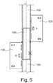
- eine schematische Längsschnittansicht der Vorrichtung aus
Fig. 2 . - Die Vorrichtung umfasst einen Türflügel 100, der mit einem Türband schwenkbar an einer Türzarge 101 befestigt ist. Das Türband umfasst eine erste Bandrolle 102, eine zweite Bandrolle 103 und eine dritte Bandrolle 104. Die erste Bandrolle 102 ist mit einem bolzenartigen Verbindungsmittel 109 drehbar mit der zweiten Bandrolle 103 verbunden. Die zweite Bandrolle 103 ist mit einem bolzenartigen Verbindungsmittel 110 drehbar mit der dritten Bandrolle 104 verbunden. Dabei ist die erste Bandrolle 102 oberhalb der zweiten Bandrolle 103 angeordnet, die wiederum oberhalb der dritten Bandrolle 104 angeordnet ist.
- Die erste Bandrolle 102 ist über einen Bandlappen 105 am Türflügel 100 befestigt. Die zweite Bandrolle 103 ist über einen Bandlappen 106 und einen Bandlappen 107 an der Türzarge 101 befestigt. Die dritte Bandrolle 104 ist über einen Bandlappen 108 am Türflügel 100 befestigt. Die Befestigung mit den Bandlappen 105,106, 107 und 108 ist besonders stabil. Außerdem lässt sich der Türflügel 100 so besonders einfach an der Türzarge 101 montieren.
- Die Bandrollen 102, 103 und 104 erstrecken sich über die gesamte Höhe des Türflügels 100. Somit wird der gesamte Spalt zwischen dem Türflügel 100 und der Türzarge 101, insbesondere im geöffneten Zustand der Tür, durch die Bandrollen 102, 103 und 104 verdeckt. Die Bandrollen erfüllen somit eine Klemmschutzfunktion.
- Die in
Figur 2 dargestellte Vorrichtung unterscheidet sich vor allem durch die Befestigung der Bandrollen 102, 103 und 104 von der inFigur 1 dargestellten Vorrichtung. So ist die oberste erste Bandrolle 102 mit dem Bandlappen 105 an der Türzarge 101 befestigt. Die darunter angeordnete zweite Bandrolle 103 ist mit den Bandlappen 106 und 107 am Türflügel 100 befestigt. Die unterhalb der zweiten Bandrolle 103 angeordnete dritte Bandrolle 104 ist mit dem Bandlappen 108 an der Türzarge befestigt. - Bei den
Figuren 3 und 4 handelt es sich um Schnittansichten entlang einer stufenförmigen Schnittlinie. Diese Darstellung wurde gewählt, um deutlich zu machen, dass die Bandrollen 102 und 103 denselben Durchmesser aufweisen. In der Schnittansicht ist das bolzenartige Verbindungsmittel 109 folglich nur zur Hälfte dargestellt. - In
Figur 3 sind die Bandrollen 102 und 103 mit Schrauben 301 an der Türzarge 101 und dem Türflügel 100 befestigt. Mit den Schrauben 301 sind ebenfalls ein erstes Dichtungselement 304 und ein zweites Dichtungselement 305 zwischen den Bandrollen 102 und 103 und dem Türflügel 100 beziehungsweise der Türzarge 101 befestigt. - In dem in den
Figuren 3 und 4 dargestellten Zustand verschließt der Türflügel 100 eine durch die Türzarge 101 definierte Türöffnung. Aus diesem Grund sind die Bandrollen an einer Zargeninnenseite 300 Türzarge 101 angeordnet. - Der Türflügel 100 weist eine Nut 303 auf, in die ein entsprechend geformter Abschnitt des ersten Dichtungselements 304 hineinragt. Die Türzarge 101 weist eine Nut 302 auf, in die ein entsprechend geformter Abschnitt des zweiten Dichtungselements 305 ragt. Die beiden Dichtungselemente 304 und 305 sind somit zusätzlich zur Befestigung mit den Schrauben 301 formschlüssig am Türflügel 100 beziehungsweise an der Türzarge 101 befestigt. Die Nuten 302 und 303 sind insbesondere vorteilhaft für eine einfache Montage der Dichtungselemente 304 an dem Türflügel 100 und an der Türzarge 101. So kann der Türflügel 100 beispielsweise wie aus dem Stand der Technik bekannt eingesetzt werden. Das erste Dichtungselement 304 kann einfach nachgerüstet werden, indem der entsprechende Abschnitt in die Nut 303 eingesetzt wird.
- Das erste Dichtungselement 304 weist einen Stauchbereich 306 auf, der auch als Dichtlippe bezeichnet werden kann. Im in den
Figuren 3 und 4 dargestellten geschlossenen Zustand des Türflügels 100 wird der Stauchbereich 306 durch das zweite Dichtungselement 305 gestaucht. Wenn der Türflügel 100 geöffnet wird, streckt sich der Stauchbereich 306 und kommt zur Anlage an den Bandrollen 102 und 103. Auf diese Weise wird eine zuverlässige Abdichtung sowohl im geschlossenen als auch im geöffneten Zustand des Türflügels 100 erreicht. - Das erste Dichtugnselement 304 weist außerdem eine Dichtlippe 307 auf, die gegen die Bandrollen 102 und 103 gedrückt wird und so weiter die Dichtigkeit der Vorrichtung erhöht. Außerdem weist das erste Dichtungselement 304 Ausnehmungen auf, in die weitere Dichtungselemente 308 eingesetzt sind, um ebenfalls die Dichtigkeit der Vorrichtung zu erhöhen. Bei der in
Figur 4 dargestellten Vorrichtung weist ebenfalls das zweite Dichtungselement 305 eine solche Ausnehmung auf, in die ebenfalls ein Dichtungselement 308 eingesetzt ist. - Das erste Dichtungselement 304 und das zweite Dichtungselement 305 weisen einen kreisabschnittsförmigen Bereich auf, der den gleichen Radius aufweist wie die Bandrollen 102 und 103. So kann eine zuverlässige Abdichtung erreicht werden. Zusätzlich ist bei der in
Figur 3 dargestellten Vorrichtung jeweils noch ein weiteres Dichtungselement 309 zwischen dem kreisabschnittsförmigen Bereich des ersten Dichtungselements 304 und den Bandrollen 102 und 103 und zwischen dem kreisabschnittsförmigen Bereich des zweiten Dichtungselements 305 und den Bandrollen 102 und 103 angeordnet, wodurch die Dichtigkeit noch weiter erhöht wird. - Die in
Figur 4 dargestellte Vorrichtung unterscheidet sich von der inFigur 3 dargestellten Vorrichtung insbesondere durch die Befestigung der Bandrollen 102 und 103 am Türflügel 100 und an der Türzarge 101. InFigur 4 ist die erste Bandrolle 102 mit einem ersten Bandlappen 105 am Türflügel 100 befestigt. Die zweite Bandrolle 103 ist mit einem zweiten Bandlappen 106 an der Türzarge 101 befestigt. Die Bandlappen 105 und 106 können beispielsweise mit Schrauben am Türflügel 100 beziehungsweise an der Türzarge 101 befestigt sein. Die Bandlappen 105 und 106 können zu diesem Zweck Langlöcher aufweisen. Dies erlaubt eine Verschiebbarkeit der Bandlappen 105 und 106. Die Bandlappen 105 und 106 können außerdem durch Abdeckmittel abgedeckt sein. - Ein weiterer Unterscheid ist, dass bei der Vorrichtung in
Figur 4 auf die Dichtungselemente 309 verzichtet wurde. - In
Figur 5 ist dargestellt, dass die beiden Bandrollen 102 und 103 durch das Verbindungsmittel 109 miteinander drehbar verbunden sind. Zu diesem Zweck ist das Verbindungsmittel 109 bolzenartig ausgebildet und fest mit einer der beiden Bandrollen 102 und 103 verbunden. Außerdem ist eine Führungsbuchse zwischen dem Verbindungsmittel 109 und den Bandrollen 102 und 103 angeordnet.
Claims (14)
- Vorrichtung zur schwenkbaren Befestigung eines Türflügels (100) an einer Türzarge (101), umfassend den Türflügel (100) und ein Türband mit mehreren Bandrollen (102; 103; 104), wobei zumindest eine erste der Bandrollen (102; 103; 104) am Türflügel (100) befestigt ist, wobei jeweils zwei der Bandrollen (102; 103; 104) miteinander verbunden sind, wobei der Türflügel (100) eine Höhe aufweist, wobei sich das Türband über die gesamte Höhe des Türflügels (100) erstreckt,
dadurch gekennzeichnet, dass
zumindest eine zweite der Bandrollen (102; 103; 104) für eine Befestigung an der Türzarge (101) ausgebildet ist. - Vorrichtung nach dem vorherigen Anspruch, dadurch gekennzeichnet, dass die Vorrichtung zumindest drei Bandrollen (102; 103; 104) umfasst.
- Vorrichtung nach zumindest einem der vorherigen Ansprüche,
dadurch gekennzeichnet, dass die Bandrollen (102; 103; 104) als Rundrohre ausgebildet sind und denselben Durchmesser aufweisen. - Vorrichtung nach zumindest einem der vorherigen Ansprüche,
dadurch gekennzeichnet, dass das Türband bolzenartige Verbindungselemente (109; 110) umfasst, wobei jeweils zwei der Bandrollen (102; 103; 104) über die Verbindungselemente (109; 110) miteinander verbunden sind. - Vorrichtung nach zumindest einem der vorherigen Ansprüche,
dadurch gekennzeichnet, dass die Vorrichtung ein Dichtungsmittel (304; 305; 308; 309) umfasst, wobei das Dichtungsmittel (304; 305; 308; 309) am Türflügel (100) befestigt und an der Türzarge (101) befestigbar ist, wobei das Dichtungsmittel (304; 305; 308; 309) dazu ausgebildet ist, im an der Türzarge (101) befestigten Zustand einen Spalt zwischen dem Türflügel (100) und der Türzarge (101) abzudichten. - Vorrichtung nach dem vorherigen Anspruch, dadurch gekennzeichnet, dass das Dichtungsmittel (304; 305; 308; 309) zumindest einen Anlagebereich zur Anlage an den Bandrollen (102; 103; 104) aufweist, wobei der Anlagebereich als Kreisabschnitt ausgebildet ist, und wobei der Kreisabschnitt einen Radius aufweist, der dem Radius der Bandrollen (102; 103; 104) entspricht.
- Vorrichtung nach einem der beiden vorherigen Ansprüche,
dadurch gekennzeichnet, dass das Dichtungsmittel (304; 305; 308; 309) mehrere Dichtungselemente (304; 305; 308; 309) umfasst, wobei ein erstes der Dichtungselemente (304; 305; 308; 309) im an der Türzarge (101) angebrachten Zustand des Türflügels (100) durch ein zweites der Dichtungselemente (304; 305; 308; 309) gestaucht wird, wenn der Türflügel (100) eine durch die Türzarge (101) definierte Türöffnung verschließt. - Vorrichtung nach zumindest einem der drei vorherigen Ansprüche, dadurch gekennzeichnet, dass das Dichtungsmittel (304; 305; 308; 309) mehrere Dichtungselemente (304; 305; 308; 309) umfasst, wobei ein drittes der Dichtungselemente (304; 305; 308; 309) in Ausnehmungen des ersten Dichtungselements (304) und/oder des zweiten Dichtungselements (305) eingesetzt ist.
- Vorrichtung nach zumindest einem der vorherigen Ansprüche,
dadurch gekennzeichnet, dass das Türband mehrere Bandlappen (105; 106; 107; 108) umfasst, wobei die Bandrollen (102; 103; 104) mittels der Bandlappen (105; 106; 107; 108) am Türflügel (100) befestigt beziehungsweise an der Türzarge (101) befestigbar ist. - Vorrichtung nach zumindest einem der Ansprüche 1 bis 8,
dadurch gekennzeichnet, dass die Bandrollen (102; 103; 104) jeweils mit einer Schraubverbindung am Türflügel (100) befestigt beziehungsweise an der Türzarge befestigbar sind. - Vorrichtung nach zumindest einem der vorherigen Ansprüche,
dadurch gekennzeichnet, dass die Vorrichtung ein erstes Dichtprofil umfasst, das in einem ersten Randbereich des Türflügels (100) angeordnet ist, wobei das erste Dichtprofil dazu ausgebildet ist, im an der Türzarge (101) angebrachten Zustand des Türflügels (100) einen horizontalen Bereich zwischen dem Türflügel (100) und der Türzarge (101) abzudichten. - Vorrichtung nach zumindest einem der vorherigen Ansprüche,
dadurch gekennzeichnet, dass die Vorrichtung ein zweites Dichtprofil umfasst, das in einem zweiten Randbereich des Türflügels (100) angeordnet ist, wobei das zweite Dichtprofil dazu ausgebildet ist, im an der Türzarge (101) angebrachten Zustand des Türflügels (100) einen horizontalen Bereich zwischen dem Türflügel (100) und einer Schwelle und/oder einem Boden abzudichten. - Vorrichtung nach zumindest einem der vorherigen Ansprüche,
dadurch gekennzeichnet, dass die Vorrichtung ein drittes Dichtprofil umfasst, das an einer Oberfläche des Türflügels (100) angeordnet ist und sich im an der Türzarge (101) angebrachten Zustand des Türflügels (100) in einer vertikalen Richtung erstreckt, wobei das dritte Dichtprofil in einem dritten Randbereich des Türflügels (100) angeordnet ist, wobei der dritte Randbereich einem vierten Randbereich des Türflügels (100) gegenüber angeordnet ist, und wobei die Bandrollen (102; 103; 104) am vierten Randbereich angeordnet sind. - System, umfassend eine Vorrichtung nach zumindest einem der vorherigen Ansprüche und eine Türzarge (101), wobei der Türflügel (100) mittels der Vorrichtung an der Türzarge (101) befestigt ist.
Priority Applications (12)
| Application Number | Priority Date | Filing Date | Title |
|---|---|---|---|
| DK17151491.2T DK3348760T3 (da) | 2017-01-13 | 2017-01-13 | Indretning til drejelig fastgørelse af en dørplade i en dørkarm |
| EP17151491.2A EP3348760B1 (de) | 2017-01-13 | 2017-01-13 | Vorrichtung zur schwenkbaren befestigung eines türflügels an einer türzarge |
| PL17151491T PL3348760T3 (pl) | 2017-01-13 | 2017-01-13 | Urządzenie do odchylnego mocowania skrzydła drzwi na ościeżnicy drzwi |
| ES17151491T ES2791476T3 (es) | 2017-01-13 | 2017-01-13 | Dispositivo para la fijación pivotante de una hoja de puerta a un marco de puerta |
| PL18151463T PL3348761T3 (pl) | 2017-01-13 | 2018-01-12 | Urządzenie do obrotowego mocowania skrzydła drzwi do ościeżnicy drzwi |
| EP18151463.9A EP3348761B1 (de) | 2017-01-13 | 2018-01-12 | Vorrichtung zur schwenkbaren befestigung eines türflügels an einer türzarge |
| ES20214295T ES2932549T3 (es) | 2017-01-13 | 2019-01-10 | Dispositivo para la fijación pivotante de una hoja de puerta a un marco de puerta |
| PL20214295.6T PL3808926T3 (pl) | 2017-01-13 | 2019-01-10 | Urządzenie do odchylnego mocowania skrzydła drzwi na ościeżnicy drzwi |
| EP20214295.6A EP3808926B1 (de) | 2017-01-13 | 2019-01-10 | Vorrichtung zur schwenkbaren befestigung eines türflügels an einer türzarge |
| ES19151258T ES2872260T3 (es) | 2017-01-13 | 2019-01-10 | Dispositivo para la fijación pivotante de una hoja de puerta a un marco de puerta |
| PL19151258T PL3511499T3 (pl) | 2017-01-13 | 2019-01-10 | Urządzenie do odchylnego mocowania skrzydła drzwi na ościeżnicy drzwi |
| EP19151258.1A EP3511499B1 (de) | 2017-01-13 | 2019-01-10 | Vorrichtung zur schwenkbaren befestigung eines türflügels an einer türzarge |
Applications Claiming Priority (1)
| Application Number | Priority Date | Filing Date | Title |
|---|---|---|---|
| EP17151491.2A EP3348760B1 (de) | 2017-01-13 | 2017-01-13 | Vorrichtung zur schwenkbaren befestigung eines türflügels an einer türzarge |
Publications (2)
| Publication Number | Publication Date |
|---|---|
| EP3348760A1 true EP3348760A1 (de) | 2018-07-18 |
| EP3348760B1 EP3348760B1 (de) | 2020-03-11 |
Family
ID=57796271
Family Applications (4)
| Application Number | Title | Priority Date | Filing Date |
|---|---|---|---|
| EP17151491.2A Active EP3348760B1 (de) | 2017-01-13 | 2017-01-13 | Vorrichtung zur schwenkbaren befestigung eines türflügels an einer türzarge |
| EP18151463.9A Active EP3348761B1 (de) | 2017-01-13 | 2018-01-12 | Vorrichtung zur schwenkbaren befestigung eines türflügels an einer türzarge |
| EP19151258.1A Active EP3511499B1 (de) | 2017-01-13 | 2019-01-10 | Vorrichtung zur schwenkbaren befestigung eines türflügels an einer türzarge |
| EP20214295.6A Active EP3808926B1 (de) | 2017-01-13 | 2019-01-10 | Vorrichtung zur schwenkbaren befestigung eines türflügels an einer türzarge |
Family Applications After (3)
| Application Number | Title | Priority Date | Filing Date |
|---|---|---|---|
| EP18151463.9A Active EP3348761B1 (de) | 2017-01-13 | 2018-01-12 | Vorrichtung zur schwenkbaren befestigung eines türflügels an einer türzarge |
| EP19151258.1A Active EP3511499B1 (de) | 2017-01-13 | 2019-01-10 | Vorrichtung zur schwenkbaren befestigung eines türflügels an einer türzarge |
| EP20214295.6A Active EP3808926B1 (de) | 2017-01-13 | 2019-01-10 | Vorrichtung zur schwenkbaren befestigung eines türflügels an einer türzarge |
Country Status (4)
| Country | Link |
|---|---|
| EP (4) | EP3348760B1 (de) |
| DK (1) | DK3348760T3 (de) |
| ES (3) | ES2791476T3 (de) |
| PL (4) | PL3348760T3 (de) |
Cited By (1)
| Publication number | Priority date | Publication date | Assignee | Title |
|---|---|---|---|---|
| KR102192905B1 (ko) * | 2020-06-01 | 2020-12-18 | 주식회사 신흥코리아 | 여닫이 문 모서리 안전장치 |
Families Citing this family (3)
| Publication number | Priority date | Publication date | Assignee | Title |
|---|---|---|---|---|
| DE102019100645A1 (de) | 2019-01-11 | 2020-07-16 | Hörmann Kg Ichtershausen | Klemmschutzsystem für Einfriedungs- und/oder Gebäudeabschlüsse, Anordnung mit Klemmschutzsystem, sowie Einfriedungs- und/oder Gebäudeabschluss |
| PL4431694T3 (pl) * | 2023-03-15 | 2025-12-15 | Athmer Ohg | Urządzenie do otwierania i zamykania drzwi |
| DE202024103866U1 (de) * | 2024-07-11 | 2025-10-14 | Simonswerk Gmbh | Türband und Tür |
Citations (6)
| Publication number | Priority date | Publication date | Assignee | Title |
|---|---|---|---|---|
| US2557716A (en) * | 1945-12-07 | 1951-06-19 | Moynahan Bronze Company | Safety hinge |
| US3646636A (en) * | 1970-07-20 | 1972-03-07 | Paul M Hives | Door hinge |
| DE2518743A1 (de) * | 1975-04-26 | 1976-11-04 | Vincenzo Di Mauro | Sicherheitsscharnier fuer tueren und fenster |
| EP1114906A2 (de) * | 2000-01-05 | 2001-07-11 | Jamco Corporation | Scharnierteil |
| DE102013113670A1 (de) | 2012-12-20 | 2014-06-26 | Alfons Albersmann | Tür mit Fingerklemmschutz |
| EP2813655A1 (de) * | 2013-06-13 | 2014-12-17 | DORMA Deutschland GmbH | Türanlage mit zumindest einem schwenkbaren Seitenteil |
Family Cites Families (3)
| Publication number | Priority date | Publication date | Assignee | Title |
|---|---|---|---|---|
| US20060254024A1 (en) * | 2005-05-10 | 2006-11-16 | Teng-Long Yong | Seamless interlocking hinge assembly |
| KR101342651B1 (ko) * | 2013-05-30 | 2013-12-20 | 노승현 | 끼임방지용 여닫이문 |
| US9879471B2 (en) * | 2015-09-30 | 2018-01-30 | Woodfold Mfg., Inc. | Reinforced folding door and hinge assembly |
-
2017
- 2017-01-13 DK DK17151491.2T patent/DK3348760T3/da active
- 2017-01-13 PL PL17151491T patent/PL3348760T3/pl unknown
- 2017-01-13 ES ES17151491T patent/ES2791476T3/es active Active
- 2017-01-13 EP EP17151491.2A patent/EP3348760B1/de active Active
-
2018
- 2018-01-12 PL PL18151463T patent/PL3348761T3/pl unknown
- 2018-01-12 EP EP18151463.9A patent/EP3348761B1/de active Active
-
2019
- 2019-01-10 EP EP19151258.1A patent/EP3511499B1/de active Active
- 2019-01-10 EP EP20214295.6A patent/EP3808926B1/de active Active
- 2019-01-10 ES ES19151258T patent/ES2872260T3/es active Active
- 2019-01-10 PL PL20214295.6T patent/PL3808926T3/pl unknown
- 2019-01-10 PL PL19151258T patent/PL3511499T3/pl unknown
- 2019-01-10 ES ES20214295T patent/ES2932549T3/es active Active
Patent Citations (6)
| Publication number | Priority date | Publication date | Assignee | Title |
|---|---|---|---|---|
| US2557716A (en) * | 1945-12-07 | 1951-06-19 | Moynahan Bronze Company | Safety hinge |
| US3646636A (en) * | 1970-07-20 | 1972-03-07 | Paul M Hives | Door hinge |
| DE2518743A1 (de) * | 1975-04-26 | 1976-11-04 | Vincenzo Di Mauro | Sicherheitsscharnier fuer tueren und fenster |
| EP1114906A2 (de) * | 2000-01-05 | 2001-07-11 | Jamco Corporation | Scharnierteil |
| DE102013113670A1 (de) | 2012-12-20 | 2014-06-26 | Alfons Albersmann | Tür mit Fingerklemmschutz |
| EP2813655A1 (de) * | 2013-06-13 | 2014-12-17 | DORMA Deutschland GmbH | Türanlage mit zumindest einem schwenkbaren Seitenteil |
Cited By (1)
| Publication number | Priority date | Publication date | Assignee | Title |
|---|---|---|---|---|
| KR102192905B1 (ko) * | 2020-06-01 | 2020-12-18 | 주식회사 신흥코리아 | 여닫이 문 모서리 안전장치 |
Also Published As
| Publication number | Publication date |
|---|---|
| PL3348760T3 (pl) | 2020-08-10 |
| EP3348761A1 (de) | 2018-07-18 |
| EP3511499A1 (de) | 2019-07-17 |
| EP3808926A1 (de) | 2021-04-21 |
| PL3348761T3 (pl) | 2021-12-06 |
| EP3348760B1 (de) | 2020-03-11 |
| PL3511499T3 (pl) | 2021-10-11 |
| EP3511499B1 (de) | 2021-03-10 |
| EP3348761B1 (de) | 2021-05-05 |
| ES2932549T3 (es) | 2023-01-20 |
| DK3348760T3 (da) | 2020-05-25 |
| EP3808926B1 (de) | 2022-09-28 |
| ES2872260T3 (es) | 2021-11-02 |
| PL3808926T3 (pl) | 2023-02-27 |
| ES2791476T3 (es) | 2020-11-04 |
Similar Documents
| Publication | Publication Date | Title |
|---|---|---|
| DE4309088C2 (de) | Ortsfest einbaubare Scheibe für Kraftfahrzeuge | |
| EP3572605A1 (de) | Scharnieranordnung für ein schaltschrankgehäuse und ein entsprechendes schaltschrankgehäuse | |
| EP3348760B1 (de) | Vorrichtung zur schwenkbaren befestigung eines türflügels an einer türzarge | |
| DE102021129920B3 (de) | Türband und Tür | |
| DE3843095A1 (de) | Befestigungseinrichtung fuer verkleidungen | |
| EP3326249B1 (de) | Anordnung aus einem dachaufbau und einem befestigunssystem für die befestigung des dachaufbaus in einem ausschnitt auf dem dach eines schaltschranks | |
| DE2754697A1 (de) | Verbesserungen zu einer klemmschelle | |
| EP3425155B1 (de) | Klemmschutzeinrichtung für eine tür | |
| EP1045098B1 (de) | Stangenverschluss mit Rundstange | |
| EP2951374B1 (de) | Laufteil zum führen eines möbelteils in einer führungsrichtung über eine führungsschiene und möbelbeschlag | |
| EP3680443B1 (de) | Drehflügeltor mit klemmschutzsystem | |
| EP2708693B1 (de) | Schiebeflügelrahmen | |
| EP3203006B1 (de) | Dichtungsprofil für eine tür | |
| DE202008016071U1 (de) | Band zur scharniergelenkigen Verbindung eines Flügels an einem Rahmen | |
| DE102007007457A1 (de) | Innenverkleidung für eine Kraftfahrzeugtür | |
| DE202016101599U1 (de) | Dichtungsprofil für eine Tür | |
| EP2385200B1 (de) | Beschlagteil zur Befestigung an einer C-förmigen Beschlagteilnut | |
| EP3241964B1 (de) | Bandlappen eines Bandes und System | |
| CH656915A5 (de) | Vorrichtung zur kupplung senkrecht zueinander verlaufender treibstangen. | |
| DE102022205376B4 (de) | Gleitschiene für einen Türantrieb | |
| DE9101597U1 (de) | Scharnier | |
| DE29600891U1 (de) | Sicherungseinrichtung | |
| DE19810365C2 (de) | Scharnier | |
| DE3242100C2 (de) | ||
| EP2192075A1 (de) | Seilflasche |
Legal Events
| Date | Code | Title | Description |
|---|---|---|---|
| PUAI | Public reference made under article 153(3) epc to a published international application that has entered the european phase |
Free format text: ORIGINAL CODE: 0009012 |
|
| STAA | Information on the status of an ep patent application or granted ep patent |
Free format text: STATUS: THE APPLICATION HAS BEEN PUBLISHED |
|
| AK | Designated contracting states |
Kind code of ref document: A1 Designated state(s): AL AT BE BG CH CY CZ DE DK EE ES FI FR GB GR HR HU IE IS IT LI LT LU LV MC MK MT NL NO PL PT RO RS SE SI SK SM TR |
|
| AX | Request for extension of the european patent |
Extension state: BA ME |
|
| STAA | Information on the status of an ep patent application or granted ep patent |
Free format text: STATUS: REQUEST FOR EXAMINATION WAS MADE |
|
| 17P | Request for examination filed |
Effective date: 20190118 |
|
| RBV | Designated contracting states (corrected) |
Designated state(s): AL AT BE BG CH CY CZ DE DK EE ES FI FR GB GR HR HU IE IS IT LI LT LU LV MC MK MT NL NO PL PT RO RS SE SI SK SM TR |
|
| RIC1 | Information provided on ipc code assigned before grant |
Ipc: E06B 7/36 20060101ALI20190604BHEP Ipc: E05D 3/02 20060101AFI20190604BHEP Ipc: E05D 7/00 20060101ALN20190604BHEP Ipc: E05D 11/00 20060101ALI20190604BHEP |
|
| GRAP | Despatch of communication of intention to grant a patent |
Free format text: ORIGINAL CODE: EPIDOSNIGR1 |
|
| STAA | Information on the status of an ep patent application or granted ep patent |
Free format text: STATUS: GRANT OF PATENT IS INTENDED |
|
| INTG | Intention to grant announced |
Effective date: 20190729 |
|
| GRAS | Grant fee paid |
Free format text: ORIGINAL CODE: EPIDOSNIGR3 |
|
| GRAA | (expected) grant |
Free format text: ORIGINAL CODE: 0009210 |
|
| STAA | Information on the status of an ep patent application or granted ep patent |
Free format text: STATUS: THE PATENT HAS BEEN GRANTED |
|
| AK | Designated contracting states |
Kind code of ref document: B1 Designated state(s): AL AT BE BG CH CY CZ DE DK EE ES FI FR GB GR HR HU IE IS IT LI LT LU LV MC MK MT NL NO PL PT RO RS SE SI SK SM TR |
|
| REG | Reference to a national code |
Ref country code: GB Ref legal event code: FG4D Free format text: NOT ENGLISH |
|
| REG | Reference to a national code |
Ref country code: CH Ref legal event code: EP |
|
| REG | Reference to a national code |
Ref country code: AT Ref legal event code: REF Ref document number: 1243327 Country of ref document: AT Kind code of ref document: T Effective date: 20200315 |
|
| REG | Reference to a national code |
Ref country code: IE Ref legal event code: FG4D Free format text: LANGUAGE OF EP DOCUMENT: GERMAN |
|
| REG | Reference to a national code |
Ref country code: DE Ref legal event code: R096 Ref document number: 502017004134 Country of ref document: DE |
|
| REG | Reference to a national code |
Ref country code: DK Ref legal event code: T3 Effective date: 20200520 |
|
| REG | Reference to a national code |
Ref country code: NL Ref legal event code: FP |
|
| REG | Reference to a national code |
Ref country code: SE Ref legal event code: TRGR |
|
| REG | Reference to a national code |
Ref country code: NO Ref legal event code: T2 Effective date: 20200311 |
|
| PG25 | Lapsed in a contracting state [announced via postgrant information from national office to epo] |
Ref country code: RS Free format text: LAPSE BECAUSE OF FAILURE TO SUBMIT A TRANSLATION OF THE DESCRIPTION OR TO PAY THE FEE WITHIN THE PRESCRIBED TIME-LIMIT Effective date: 20200311 Ref country code: FI Free format text: LAPSE BECAUSE OF FAILURE TO SUBMIT A TRANSLATION OF THE DESCRIPTION OR TO PAY THE FEE WITHIN THE PRESCRIBED TIME-LIMIT Effective date: 20200311 |
|
| PG25 | Lapsed in a contracting state [announced via postgrant information from national office to epo] |
Ref country code: HR Free format text: LAPSE BECAUSE OF FAILURE TO SUBMIT A TRANSLATION OF THE DESCRIPTION OR TO PAY THE FEE WITHIN THE PRESCRIBED TIME-LIMIT Effective date: 20200311 Ref country code: LV Free format text: LAPSE BECAUSE OF FAILURE TO SUBMIT A TRANSLATION OF THE DESCRIPTION OR TO PAY THE FEE WITHIN THE PRESCRIBED TIME-LIMIT Effective date: 20200311 Ref country code: BG Free format text: LAPSE BECAUSE OF FAILURE TO SUBMIT A TRANSLATION OF THE DESCRIPTION OR TO PAY THE FEE WITHIN THE PRESCRIBED TIME-LIMIT Effective date: 20200611 Ref country code: GR Free format text: LAPSE BECAUSE OF FAILURE TO SUBMIT A TRANSLATION OF THE DESCRIPTION OR TO PAY THE FEE WITHIN THE PRESCRIBED TIME-LIMIT Effective date: 20200612 |
|
| REG | Reference to a national code |
Ref country code: LT Ref legal event code: MG4D |
|
| PG25 | Lapsed in a contracting state [announced via postgrant information from national office to epo] |
Ref country code: EE Free format text: LAPSE BECAUSE OF FAILURE TO SUBMIT A TRANSLATION OF THE DESCRIPTION OR TO PAY THE FEE WITHIN THE PRESCRIBED TIME-LIMIT Effective date: 20200311 Ref country code: SM Free format text: LAPSE BECAUSE OF FAILURE TO SUBMIT A TRANSLATION OF THE DESCRIPTION OR TO PAY THE FEE WITHIN THE PRESCRIBED TIME-LIMIT Effective date: 20200311 Ref country code: CZ Free format text: LAPSE BECAUSE OF FAILURE TO SUBMIT A TRANSLATION OF THE DESCRIPTION OR TO PAY THE FEE WITHIN THE PRESCRIBED TIME-LIMIT Effective date: 20200311 Ref country code: IS Free format text: LAPSE BECAUSE OF FAILURE TO SUBMIT A TRANSLATION OF THE DESCRIPTION OR TO PAY THE FEE WITHIN THE PRESCRIBED TIME-LIMIT Effective date: 20200711 Ref country code: SK Free format text: LAPSE BECAUSE OF FAILURE TO SUBMIT A TRANSLATION OF THE DESCRIPTION OR TO PAY THE FEE WITHIN THE PRESCRIBED TIME-LIMIT Effective date: 20200311 Ref country code: RO Free format text: LAPSE BECAUSE OF FAILURE TO SUBMIT A TRANSLATION OF THE DESCRIPTION OR TO PAY THE FEE WITHIN THE PRESCRIBED TIME-LIMIT Effective date: 20200311 Ref country code: PT Free format text: LAPSE BECAUSE OF FAILURE TO SUBMIT A TRANSLATION OF THE DESCRIPTION OR TO PAY THE FEE WITHIN THE PRESCRIBED TIME-LIMIT Effective date: 20200805 Ref country code: LT Free format text: LAPSE BECAUSE OF FAILURE TO SUBMIT A TRANSLATION OF THE DESCRIPTION OR TO PAY THE FEE WITHIN THE PRESCRIBED TIME-LIMIT Effective date: 20200311 |
|
| REG | Reference to a national code |
Ref country code: ES Ref legal event code: FG2A Ref document number: 2791476 Country of ref document: ES Kind code of ref document: T3 Effective date: 20201104 |
|
| REG | Reference to a national code |
Ref country code: DE Ref legal event code: R097 Ref document number: 502017004134 Country of ref document: DE |
|
| PLBE | No opposition filed within time limit |
Free format text: ORIGINAL CODE: 0009261 |
|
| STAA | Information on the status of an ep patent application or granted ep patent |
Free format text: STATUS: NO OPPOSITION FILED WITHIN TIME LIMIT |
|
| 26N | No opposition filed |
Effective date: 20201214 |
|
| PG25 | Lapsed in a contracting state [announced via postgrant information from national office to epo] |
Ref country code: SI Free format text: LAPSE BECAUSE OF FAILURE TO SUBMIT A TRANSLATION OF THE DESCRIPTION OR TO PAY THE FEE WITHIN THE PRESCRIBED TIME-LIMIT Effective date: 20200311 |
|
| REG | Reference to a national code |
Ref country code: DK Ref legal event code: EBP Effective date: 20210131 |
|
| PG25 | Lapsed in a contracting state [announced via postgrant information from national office to epo] |
Ref country code: MC Free format text: LAPSE BECAUSE OF FAILURE TO SUBMIT A TRANSLATION OF THE DESCRIPTION OR TO PAY THE FEE WITHIN THE PRESCRIBED TIME-LIMIT Effective date: 20200311 |
|
| PG25 | Lapsed in a contracting state [announced via postgrant information from national office to epo] |
Ref country code: LU Free format text: LAPSE BECAUSE OF NON-PAYMENT OF DUE FEES Effective date: 20210113 |
|
| REG | Reference to a national code |
Ref country code: BE Ref legal event code: MM Effective date: 20210131 |
|
| PG25 | Lapsed in a contracting state [announced via postgrant information from national office to epo] |
Ref country code: DK Free format text: LAPSE BECAUSE OF NON-PAYMENT OF DUE FEES Effective date: 20210131 Ref country code: IE Free format text: LAPSE BECAUSE OF NON-PAYMENT OF DUE FEES Effective date: 20210113 |
|
| PG25 | Lapsed in a contracting state [announced via postgrant information from national office to epo] |
Ref country code: BE Free format text: LAPSE BECAUSE OF NON-PAYMENT OF DUE FEES Effective date: 20210131 |
|
| PG25 | Lapsed in a contracting state [announced via postgrant information from national office to epo] |
Ref country code: CY Free format text: LAPSE BECAUSE OF FAILURE TO SUBMIT A TRANSLATION OF THE DESCRIPTION OR TO PAY THE FEE WITHIN THE PRESCRIBED TIME-LIMIT Effective date: 20200311 |
|
| P01 | Opt-out of the competence of the unified patent court (upc) registered |
Effective date: 20230616 |
|
| PG25 | Lapsed in a contracting state [announced via postgrant information from national office to epo] |
Ref country code: HU Free format text: LAPSE BECAUSE OF FAILURE TO SUBMIT A TRANSLATION OF THE DESCRIPTION OR TO PAY THE FEE WITHIN THE PRESCRIBED TIME-LIMIT; INVALID AB INITIO Effective date: 20170113 |
|
| PG25 | Lapsed in a contracting state [announced via postgrant information from national office to epo] |
Ref country code: MK Free format text: LAPSE BECAUSE OF FAILURE TO SUBMIT A TRANSLATION OF THE DESCRIPTION OR TO PAY THE FEE WITHIN THE PRESCRIBED TIME-LIMIT Effective date: 20200311 |
|
| PG25 | Lapsed in a contracting state [announced via postgrant information from national office to epo] |
Ref country code: TR Free format text: LAPSE BECAUSE OF FAILURE TO SUBMIT A TRANSLATION OF THE DESCRIPTION OR TO PAY THE FEE WITHIN THE PRESCRIBED TIME-LIMIT Effective date: 20200311 |
|
| PG25 | Lapsed in a contracting state [announced via postgrant information from national office to epo] |
Ref country code: MT Free format text: LAPSE BECAUSE OF FAILURE TO SUBMIT A TRANSLATION OF THE DESCRIPTION OR TO PAY THE FEE WITHIN THE PRESCRIBED TIME-LIMIT Effective date: 20200311 |
|
| REG | Reference to a national code |
Ref country code: CH Ref legal event code: U11 Free format text: ST27 STATUS EVENT CODE: U-0-0-U10-U11 (AS PROVIDED BY THE NATIONAL OFFICE) Effective date: 20260201 |
|
| PGFP | Annual fee paid to national office [announced via postgrant information from national office to epo] |
Ref country code: NL Payment date: 20260121 Year of fee payment: 10 |
|
| PGFP | Annual fee paid to national office [announced via postgrant information from national office to epo] |
Ref country code: SE Payment date: 20260121 Year of fee payment: 10 |
|
| PGFP | Annual fee paid to national office [announced via postgrant information from national office to epo] |
Ref country code: GB Payment date: 20260123 Year of fee payment: 10 |
|
| PGFP | Annual fee paid to national office [announced via postgrant information from national office to epo] |
Ref country code: ES Payment date: 20260227 Year of fee payment: 10 |
|
| PGFP | Annual fee paid to national office [announced via postgrant information from national office to epo] |
Ref country code: NO Payment date: 20260123 Year of fee payment: 10 Ref country code: DE Payment date: 20260131 Year of fee payment: 10 |
|
| PGFP | Annual fee paid to national office [announced via postgrant information from national office to epo] |
Ref country code: AT Payment date: 20260122 Year of fee payment: 10 |
|
| PGFP | Annual fee paid to national office [announced via postgrant information from national office to epo] |
Ref country code: IT Payment date: 20260123 Year of fee payment: 10 |
|
| PGFP | Annual fee paid to national office [announced via postgrant information from national office to epo] |
Ref country code: FR Payment date: 20260123 Year of fee payment: 10 |
|
| PGFP | Annual fee paid to national office [announced via postgrant information from national office to epo] |
Ref country code: CH Payment date: 20260201 Year of fee payment: 10 |
|
| PGFP | Annual fee paid to national office [announced via postgrant information from national office to epo] |
Ref country code: PL Payment date: 20260102 Year of fee payment: 10 |