EP3348786A1 - Rotor comprenant une couverture de conduite et plaques d'étanchéité - Google Patents
Rotor comprenant une couverture de conduite et plaques d'étanchéité Download PDFInfo
- Publication number
- EP3348786A1 EP3348786A1 EP17151766.7A EP17151766A EP3348786A1 EP 3348786 A1 EP3348786 A1 EP 3348786A1 EP 17151766 A EP17151766 A EP 17151766A EP 3348786 A1 EP3348786 A1 EP 3348786A1
- Authority
- EP
- European Patent Office
- Prior art keywords
- rotor
- rotor disk
- edge portion
- axially
- disk
- Prior art date
- Legal status (The legal status is an assumption and is not a legal conclusion. Google has not performed a legal analysis and makes no representation as to the accuracy of the status listed.)
- Withdrawn
Links
- 238000007789 sealing Methods 0.000 claims abstract description 32
- 238000001816 cooling Methods 0.000 claims description 18
- 230000002093 peripheral effect Effects 0.000 description 3
- 101100390736 Danio rerio fign gene Proteins 0.000 description 2
- 101100390738 Mus musculus Fign gene Proteins 0.000 description 2
- 230000015572 biosynthetic process Effects 0.000 description 1
- 230000001419 dependent effect Effects 0.000 description 1
- 238000000926 separation method Methods 0.000 description 1
- 230000035882 stress Effects 0.000 description 1
- 230000008646 thermal stress Effects 0.000 description 1
Images


Classifications
-
- F—MECHANICAL ENGINEERING; LIGHTING; HEATING; WEAPONS; BLASTING
- F01—MACHINES OR ENGINES IN GENERAL; ENGINE PLANTS IN GENERAL; STEAM ENGINES
- F01D—NON-POSITIVE DISPLACEMENT MACHINES OR ENGINES, e.g. STEAM TURBINES
- F01D5/00—Blades; Blade-carrying members; Heating, heat-insulating, cooling or antivibration means on the blades or the members
- F01D5/02—Blade-carrying members, e.g. rotors
- F01D5/08—Heating, heat-insulating or cooling means
- F01D5/081—Cooling fluid being directed on the side of the rotor disc or at the roots of the blades
- F01D5/082—Cooling fluid being directed on the side of the rotor disc or at the roots of the blades on the side of the rotor disc
-
- F—MECHANICAL ENGINEERING; LIGHTING; HEATING; WEAPONS; BLASTING
- F01—MACHINES OR ENGINES IN GENERAL; ENGINE PLANTS IN GENERAL; STEAM ENGINES
- F01D—NON-POSITIVE DISPLACEMENT MACHINES OR ENGINES, e.g. STEAM TURBINES
- F01D5/00—Blades; Blade-carrying members; Heating, heat-insulating, cooling or antivibration means on the blades or the members
- F01D5/30—Fixing blades to rotors; Blade roots ; Blade spacers
- F01D5/3007—Fixing blades to rotors; Blade roots ; Blade spacers of axial insertion type
- F01D5/3015—Fixing blades to rotors; Blade roots ; Blade spacers of axial insertion type with side plates
-
- F—MECHANICAL ENGINEERING; LIGHTING; HEATING; WEAPONS; BLASTING
- F05—INDEXING SCHEMES RELATING TO ENGINES OR PUMPS IN VARIOUS SUBCLASSES OF CLASSES F01-F04
- F05D—INDEXING SCHEME FOR ASPECTS RELATING TO NON-POSITIVE-DISPLACEMENT MACHINES OR ENGINES, GAS-TURBINES OR JET-PROPULSION PLANTS
- F05D2260/00—Function
- F05D2260/30—Retaining components in desired mutual position
- F05D2260/33—Retaining components in desired mutual position with a bayonet coupling
Definitions
- the invention relates to the cooling air flow in the rotor, in particular a gas turbine, wherein a ring cavity is formed on the rotor with the aid of a ring cover.
- the blade retaining grooves on the rotor disk are in this case covered by sealing plates frontally.
- cooling of the rotor blades attached to the rotor is required.
- the cooling air is guided from the inside through the rotor discs to the blades.
- the annular cavity can be realized in a simple manner if a peripheral cover is used adjacent to the rotor disk.
- a peripheral cover is used adjacent to the rotor disk.
- an embodiment is known in which the two, located at the opposite axial ends, located side edges are attached to the rotor disk.
- the blade holding grooves present in the rotor disk for receiving the rotor blades are to be covered on the front side in order to enable a separation of the cooling air flowing in the blade holding grooves to the surrounding hot gas.
- the rotor disk on a circumferential outwardly opening groove, in the front side circumferentially distributed arranged sealing plates are used.
- Object of the present invention is therefore to simplify the assembly and to make the rotor disk easier if possible.
- a generic rotor is particularly suitable for use in a gas turbine. Regardless of this, the embodiment according to the invention is also suitable for use with other rotors, for example in a steam turbine.
- the rotor has at least a first rotor disk. At this are distributed in the periphery a plurality Schaufelhaltenuten. Adjacent to the first rotor disk is a peripheral annular cavity, which is formed at least in sections on the radially outwardly facing side by a circumferential annular cover.
- a first edge portion is arranged on the first rotor disc facing axial end of the ring cover on the first rotor disc such that it is mounted at least axially and radially on the first edge portion.
- the fixing in the axial direction can be provided pointing in a direction pointing towards the first rotor disk as well as in a direction pointing away from the first rotor disk.
- Analog can be provided for storage in the radial direction that the first rotor disk sections on the radially outer side of the first edge portion engages over and / or partially engages under the first edge portion on the side facing the rotor axis.
- it can be provided both that a direct contact of the first edge portion of the first rotor disk in the axial and / or radial direction takes place as well as an indirect system for axial and / or radial fixation can be provided.
- a second edge portion which is mounted at least in the radial direction on the rotor.
- the genus according to the rotor has a plurality of circumferentially distributed sealing plates.
- the sealing plates at least partially cover the blade retaining grooves in the first rotor disk on an end face.
- these are each mounted with an inner, pointing to the rotor axis, side edge at least in the axial direction with a bearing on the first rotor disk.
- the first edge portion of the ring cover has a radially outwardly facing annular collar. This serves to receive the sealing plates, in which they are axially fixed with the inner side edge between the first rotor disk and the annular collar.
- the continuation of the manner on the first rotor disk axially extending fastening projections are arranged. These are each located in the circumferential direction between the blade retaining grooves.
- the fastening projections overlap sections of the edge portion on the radially outer side, so that a bearing and support of the ring cover in the radial direction of the first rotor disc via an abutment of the first edge portion of the mounting projections is possible.
- an axial fixing of the ring cover with the first edge portion is automatically connected in a direction pointing to the first rotor disk. It can be provided in a first variant, that an indirect fixing of the first edge portion is effected by the system of the annular collar on the inner side edge and the system of the inner sideband on the first rotor disk. This embodiment is particularly useful when initially the arrangement of the sealing plates in the desired position and only subsequently the axial fixation of the ring cover takes place.
- first edge portion takes place in the first rotor disk, which acts in both directions.
- first edge portion can not move in the axial direction regardless of the execution of the second edge portion.
- first edge portion is attached to the first rotor disk by means of screws.
- a bayonet connection is used.
- the assembly of the ring cover on the first rotor disk is effected by an initially axial movement and subsequently a rotary movement about the rotor axis. In this case, mutually engage sections on the first edge section on the first rotor disk.
- the fastening projections are executed in such a way, so that with the aid of the bayonet connection is realized.
- the fastening projections have a hook-shaped configuration, so that the fastening projections can each be grasped by a section on the first edge section.
- the storage of the ring cover on the second edge portion can be designed differently, in particular taking into account thermal expansions and the shape of the ring cover as such. It is provided in a first particularly advantageous embodiment that the ring cover can slide axially relative to the rotor at the second edge portion. By omitting an axial fixation on the second edge portion, an elongation of the ring cover is made possible relative to the rotor by an axial sliding, so that stresses due to thermal stress in the ring cover are largely avoided. It is sufficient if a slight axial play on the second edge section enables thermal compensation. It is irrelevant whether briefly an axial system on the second Edge section takes place, which can be done for example due to high temperature differences, for example during startup and / or shutdown of the rotor or the gas turbine.
- the second edge portion is fixed in the axial direction on the rotor.
- This can be realized in a first variant by the second edge portion is attached to the rotor.
- the fastening of the second edge section to the rotor can be effected, for example, by screws or by a bayonet connection.
- a second variant for fixing the second edge portion on the rotor can be provided that both at the first edge portion and at the second edge portion an opposite system is present.
- the ring cover is clamped between the two edge portions in the axial direction.
- cooling air guide by utilizing the annular cavity, it is advantageous if a plurality of cooling air holes is present in the first rotor disk. It is provided that a supply of cooling air through the cooling air holes is possible. Accordingly, the cooling air bores are guided from an inner region of the rotor through a section on the first rotor disk from the inside into the annular cavity.
- annular cavity is connected in sections with the respective blade retaining grooves, so that cooling air can flow directly from the annular cavity into the blade retaining grooves and can be guided from there into the rotor blades.
- the use of the ring cover for forming the annular cavity is particularly advantageous if it is arranged at the end of the turbine section on the rotor. Consequently, the sealing plates for covering the blade retaining grooves are located downstream of the last blade row of the turbine section.
- a second rotor disk is arranged adjacent to the first rotor disk. It is provided that the second edge portion of the ring cover is mounted on the second rotor disc at least radially. It can also be provided that an axial contact and / or fixation of the second edge portion takes place on the second rotor disk. It can be provided in an advantageous embodiment that for the axial fixation of the ring cover this is fixed axially on both sides between the first rotor disk and the second rotor disk - with or without an axial clearance.
- the arrangement of the ring cover on the first rotor disk with an adjacent second rotor disk leads to the advantageous possibility of covering with the ring cover a joint between the first rotor disk and the second rotor disk. It can be provided both that the annular cavity extends over the connection point, as can also be provided that the ring cover at the second edge portion radially on the first rotor disk and the junction overlap the second rotor disk.
- the connection point can be both a flange screw connection and a spur toothing.
- other embodiments of the joint for transmitting torque can be used.
- At least one axially opening receiving groove is present on the first rotor disk or the second rotor disk.
- the receiving groove engages the second edge portion, wherein a radial Plant of the second edge portion at a radially outwardly disposed edge of the receiving groove is possible or given.
- this opens obvious from the first rotor disk pioneering, so that an assembly of the ring cover with axial movement to the first rotor disc pointing to engagement of the second ring portion is possible in the receiving groove.
- the ring cover is arranged a securing survey.
- an axially-radially extending stop is arranged on the first rotor disk or the second rotor disk.
- a system of securing survey on the stop is possible, so that a rotational movement in the circumferential direction of the ring cover is prevented relative to the first rotor disk in at least one direction.
- securing elevation is arranged on the second edge portion in a particularly advantageous manner and extends radially outward.
- the stop is formed in a particularly advantageous manner by an edge of a securing recess in the second rotor disk.
- This embodiment is particularly advantageous when using a bayonet connection for attachment of the first edge portion of the first rotor disk, which is prevented by the system of the securing survey on the stop release on the bayonet connection.
- the sealing plates have an axially extending to the rotor disk mounting shoulder. This can be provided for attachment to the fastening projections of the first rotor disk.
- offset to the mounting projections are provided on the first rotor disk axially extending from the rotor disk holding projections, wherein the respective attachment paragraph of the sealing plate on the holding projection radial direction and / or in the circumferential direction and / or comes into abutment in the axial direction.
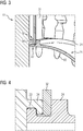
- FIG. 1 and 2 an embodiment of a rotor according to the invention is sketched in a half section in perspective views.
- the first rotor disk 01 shown on the left side and the second rotor disk 11 connected via the connection point 08 can be seen.
- the first rotor disk 01 has a plurality of blade retaining grooves 03 distributed around the circumference. These 03 are intended for receiving blades (not shown).
- Adjacent to the first rotor disk 01 is a circumferential annular cavity 09. This is further formed in sections by a flange 13 of the second rotor disk 11. Radial outer side, the annular cavity 09 is closed by the ring cover 21, which 21 between the first rotor disk 01 and the second rotor disk 11 extends.
- the blade retaining grooves 03 are partially covered by sealing plates 31 on the front side, wherein these 31 are mounted on the radially inner side between the ring cover 21 and the first rotor disk 01.
- cooling air duct with cooling air holes 06 in the first rotor disk 01 which 06 lead from a radially into that area in the annular cavity 09. From the annular cavity 09, the cooling air can flow into the blade retaining grooves 03.
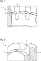
- the rotor disk 01 can be recognized as having axially extending fastening projections 04, which each have a hook-shaped configuration pointing radially to the rotor axis adjacent to the first rotor disk 01 Ring cover 21, which 21 with a first edge portion 22 on the first rotor disk 01, that is attached to the mounting projections 04. Furthermore, the arrangement of a circumferential annular collar 24 on the first edge portion 22, wherein the sealing plates 31 are axially fixed with an inner side edge 32 between the fastening projections 04 and the annular collar 24. Furthermore, the inner side edge 22 limits the movement of the sealing plates 31 radially toward the rotor axis.
- the first edge portion 22 has the circumferential annular collar 24 and a plurality of circumferentially distributed at the end of the first edge portion 22 arranged in each case radially outwardly extending bayonet paragraphs 23. These 23 distributed in multiple numbers in the circumference form the bayonet connection in cooperation with the fastening projections 04.
- the first edge portion two 20 opposite to the ring cover 21 is the second edge portion 26, on which a radially outwardly extending securing survey 27 is arranged.
Landscapes
- Engineering & Computer Science (AREA)
- Mechanical Engineering (AREA)
- General Engineering & Computer Science (AREA)
- Turbine Rotor Nozzle Sealing (AREA)
Priority Applications (1)
| Application Number | Priority Date | Filing Date | Title |
|---|---|---|---|
| EP17151766.7A EP3348786A1 (fr) | 2017-01-17 | 2017-01-17 | Rotor comprenant une couverture de conduite et plaques d'étanchéité |
Applications Claiming Priority (1)
| Application Number | Priority Date | Filing Date | Title |
|---|---|---|---|
| EP17151766.7A EP3348786A1 (fr) | 2017-01-17 | 2017-01-17 | Rotor comprenant une couverture de conduite et plaques d'étanchéité |
Publications (1)
| Publication Number | Publication Date |
|---|---|
| EP3348786A1 true EP3348786A1 (fr) | 2018-07-18 |
Family
ID=57838225
Family Applications (1)
| Application Number | Title | Priority Date | Filing Date |
|---|---|---|---|
| EP17151766.7A Withdrawn EP3348786A1 (fr) | 2017-01-17 | 2017-01-17 | Rotor comprenant une couverture de conduite et plaques d'étanchéité |
Country Status (1)
| Country | Link |
|---|---|
| EP (1) | EP3348786A1 (fr) |
Cited By (2)
| Publication number | Priority date | Publication date | Assignee | Title |
|---|---|---|---|---|
| CN114599859A (zh) * | 2019-10-18 | 2022-06-07 | 西门子能源全球有限两合公司 | 具有设置在两个转子盘之间的转子构件的转子 |
| US12037926B2 (en) | 2016-02-05 | 2024-07-16 | Siemens Energy Global GmbH & Co. KG | Rotor comprising a rotor component arranged between two rotor discs |
Citations (5)
| Publication number | Priority date | Publication date | Assignee | Title |
|---|---|---|---|---|
| GB1137630A (en) * | 1966-09-20 | 1968-12-27 | Gen Electric | Improvements in axial flow gas turbines |
| EP0169800A1 (fr) * | 1984-07-23 | 1986-01-29 | United Technologies Corporation | Assemblage d'étanchéification d'une turbine |
| US5472313A (en) * | 1991-10-30 | 1995-12-05 | General Electric Company | Turbine disk cooling system |
| EP1264964A1 (fr) * | 2001-06-07 | 2002-12-11 | Snecma Moteurs | Agencement de rotor de turbomachine à deux disques aubages séparés par une entretoise |
| EP2261461A1 (fr) * | 2008-03-28 | 2010-12-15 | Mitsubishi Heavy Industries, Ltd. | Couvercle pour passage de refroidissement, procédé de fabrication du couvercle, et turbine à gaz |
-
2017
- 2017-01-17 EP EP17151766.7A patent/EP3348786A1/fr not_active Withdrawn
Patent Citations (5)
| Publication number | Priority date | Publication date | Assignee | Title |
|---|---|---|---|---|
| GB1137630A (en) * | 1966-09-20 | 1968-12-27 | Gen Electric | Improvements in axial flow gas turbines |
| EP0169800A1 (fr) * | 1984-07-23 | 1986-01-29 | United Technologies Corporation | Assemblage d'étanchéification d'une turbine |
| US5472313A (en) * | 1991-10-30 | 1995-12-05 | General Electric Company | Turbine disk cooling system |
| EP1264964A1 (fr) * | 2001-06-07 | 2002-12-11 | Snecma Moteurs | Agencement de rotor de turbomachine à deux disques aubages séparés par une entretoise |
| EP2261461A1 (fr) * | 2008-03-28 | 2010-12-15 | Mitsubishi Heavy Industries, Ltd. | Couvercle pour passage de refroidissement, procédé de fabrication du couvercle, et turbine à gaz |
Cited By (3)
| Publication number | Priority date | Publication date | Assignee | Title |
|---|---|---|---|---|
| US12037926B2 (en) | 2016-02-05 | 2024-07-16 | Siemens Energy Global GmbH & Co. KG | Rotor comprising a rotor component arranged between two rotor discs |
| CN114599859A (zh) * | 2019-10-18 | 2022-06-07 | 西门子能源全球有限两合公司 | 具有设置在两个转子盘之间的转子构件的转子 |
| CN114599859B (zh) * | 2019-10-18 | 2023-11-17 | 西门子能源全球有限两合公司 | 具有设置在两个转子盘之间的转子构件的转子 |
Similar Documents
| Publication | Publication Date | Title |
|---|---|---|
| EP2960438B1 (fr) | Système d'aubes de guidage variables pour une turbine à gaz et turbine à gaz dotée d'un tel système | |
| EP3153667B1 (fr) | Dispositif de sécurisation axiale d'une aube mobile et dispositif de rotor équipé d'une telle sécurisation | |
| DE102014205986B4 (de) | Leitschaufelkranz und Strömungsmaschine | |
| EP3412874A1 (fr) | Bague interne d'une turbomachine divisée axiale | |
| DE1221849B (de) | Axial-Gasturbine | |
| EP2342425B1 (fr) | Turbine à gaz avec plaque de fixation entre la base d'aube et le disque | |
| EP1183444A1 (fr) | Turbomachine ainsi qu'element d'etancheite pour un rotor d'une turbomachine | |
| EP2360352B1 (fr) | Joint d'étanchéité sans vis d'une turbine à gaz | |
| DE112013001838T5 (de) | Leitschaufelsegment und dieses enthaltende Axialströmungsfluidmaschine | |
| EP3348786A1 (fr) | Rotor comprenant une couverture de conduite et plaques d'étanchéité | |
| EP2947282B1 (fr) | Boîtier intermédiaire pour une turbine à gaz et turbine à gaz | |
| EP3219911A1 (fr) | Rotor d'une turbine a gaz comprenant des disques rotoriques visses | |
| EP3109520A1 (fr) | Support d'étanchéité, stator et turbomachine | |
| EP3194725B1 (fr) | Rotor, compresseur axial, procédé de montage | |
| EP2816198B1 (fr) | Ensemble d'aube directrice, aube directrice et procédé de montage d'une aube directrice | |
| WO2003016679A1 (fr) | Anneau de fixation segmente pour les pales d'une turbine et procede pour monter et demonter ledit anneau de fixation | |
| DE102021113833B4 (de) | Anordnung zur Zentrierung zweier aneinander angrenzender Teile | |
| EP3170987B1 (fr) | Système de bague intérieure pour turbomachine | |
| EP3695100B1 (fr) | Rotor pourvu d'élément d'étanchéité et de bague d'étanchéité | |
| EP3561234B1 (fr) | Rotor pourvu de dispositif d'étanchéité | |
| EP3350416B1 (fr) | Turbine à gaz munie d'un support amélioré du carter intérieur | |
| DE102021129534A1 (de) | Leitschaufelanordnung einer Strömungsmaschine und Verfahren zur Montage einer Leitschaufelanordnung | |
| EP4013950B1 (fr) | Rotor comprenant un composant de rotor disposé entre deux disques de rotor | |
| WO2018082907A1 (fr) | Segment étanche d'un rotor et rotor | |
| EP3318723B1 (fr) | Anneau d'étanchéité d'un rotor et rotor |
Legal Events
| Date | Code | Title | Description |
|---|---|---|---|
| PUAI | Public reference made under article 153(3) epc to a published international application that has entered the european phase |
Free format text: ORIGINAL CODE: 0009012 |
|
| AK | Designated contracting states |
Kind code of ref document: A1 Designated state(s): AL AT BE BG CH CY CZ DE DK EE ES FI FR GB GR HR HU IE IS IT LI LT LU LV MC MK MT NL NO PL PT RO RS SE SI SK SM TR |
|
| AX | Request for extension of the european patent |
Extension state: BA ME |
|
| STAA | Information on the status of an ep patent application or granted ep patent |
Free format text: STATUS: THE APPLICATION IS DEEMED TO BE WITHDRAWN |
|
| 18D | Application deemed to be withdrawn |
Effective date: 20190119 |