EP3348867A1 - Drehmomentvektorisierungsvorrichtung - Google Patents
Drehmomentvektorisierungsvorrichtung Download PDFInfo
- Publication number
- EP3348867A1 EP3348867A1 EP16844238.2A EP16844238A EP3348867A1 EP 3348867 A1 EP3348867 A1 EP 3348867A1 EP 16844238 A EP16844238 A EP 16844238A EP 3348867 A1 EP3348867 A1 EP 3348867A1
- Authority
- EP
- European Patent Office
- Prior art keywords
- differential
- sun gear
- planetary gears
- torque vectoring
- drive wheel
- Prior art date
- Legal status (The legal status is an assumption and is not a legal conclusion. Google has not performed a legal analysis and makes no representation as to the accuracy of the status listed.)
- Granted
Links
Images



Classifications
-
- B—PERFORMING OPERATIONS; TRANSPORTING
- B60—VEHICLES IN GENERAL
- B60K—ARRANGEMENT OR MOUNTING OF PROPULSION UNITS OR OF TRANSMISSIONS IN VEHICLES; ARRANGEMENT OR MOUNTING OF PLURAL DIVERSE PRIME-MOVERS IN VEHICLES; AUXILIARY DRIVES FOR VEHICLES; INSTRUMENTATION OR DASHBOARDS FOR VEHICLES; ARRANGEMENTS IN CONNECTION WITH COOLING, AIR INTAKE, GAS EXHAUST OR FUEL SUPPLY OF PROPULSION UNITS IN VEHICLES
- B60K7/00—Disposition of motor in, or adjacent to, traction wheel
- B60K7/0007—Disposition of motor in, or adjacent to, traction wheel the motor being electric
-
- B—PERFORMING OPERATIONS; TRANSPORTING
- B60—VEHICLES IN GENERAL
- B60K—ARRANGEMENT OR MOUNTING OF PROPULSION UNITS OR OF TRANSMISSIONS IN VEHICLES; ARRANGEMENT OR MOUNTING OF PLURAL DIVERSE PRIME-MOVERS IN VEHICLES; AUXILIARY DRIVES FOR VEHICLES; INSTRUMENTATION OR DASHBOARDS FOR VEHICLES; ARRANGEMENTS IN CONNECTION WITH COOLING, AIR INTAKE, GAS EXHAUST OR FUEL SUPPLY OF PROPULSION UNITS IN VEHICLES
- B60K1/00—Arrangement or mounting of electrical propulsion units
- B60K1/02—Arrangement or mounting of electrical propulsion units comprising more than one electric motor
-
- B—PERFORMING OPERATIONS; TRANSPORTING
- B60—VEHICLES IN GENERAL
- B60K—ARRANGEMENT OR MOUNTING OF PROPULSION UNITS OR OF TRANSMISSIONS IN VEHICLES; ARRANGEMENT OR MOUNTING OF PLURAL DIVERSE PRIME-MOVERS IN VEHICLES; AUXILIARY DRIVES FOR VEHICLES; INSTRUMENTATION OR DASHBOARDS FOR VEHICLES; ARRANGEMENTS IN CONNECTION WITH COOLING, AIR INTAKE, GAS EXHAUST OR FUEL SUPPLY OF PROPULSION UNITS IN VEHICLES
- B60K17/00—Arrangement or mounting of transmissions in vehicles
- B60K17/04—Arrangement or mounting of transmissions in vehicles characterised by arrangement, location or kind of gearing
- B60K17/043—Transmission unit disposed in on near the vehicle wheel, or between the differential gear unit and the wheel
- B60K17/046—Transmission unit disposed in on near the vehicle wheel, or between the differential gear unit and the wheel with planetary gearing having orbital motion
-
- F—MECHANICAL ENGINEERING; LIGHTING; HEATING; WEAPONS; BLASTING
- F16—ENGINEERING ELEMENTS AND UNITS; GENERAL MEASURES FOR PRODUCING AND MAINTAINING EFFECTIVE FUNCTIONING OF MACHINES OR INSTALLATIONS; THERMAL INSULATION IN GENERAL
- F16H—GEARING
- F16H48/00—Differential gearings
- F16H48/06—Differential gearings with gears having orbital motion
- F16H48/10—Differential gearings with gears having orbital motion with orbital spur gears
- F16H48/11—Differential gearings with gears having orbital motion with orbital spur gears having intermeshing planet gears
-
- F—MECHANICAL ENGINEERING; LIGHTING; HEATING; WEAPONS; BLASTING
- F16—ENGINEERING ELEMENTS AND UNITS; GENERAL MEASURES FOR PRODUCING AND MAINTAINING EFFECTIVE FUNCTIONING OF MACHINES OR INSTALLATIONS; THERMAL INSULATION IN GENERAL
- F16H—GEARING
- F16H48/00—Differential gearings
- F16H48/36—Differential gearings characterised by intentionally generating speed difference between outputs
-
- B—PERFORMING OPERATIONS; TRANSPORTING
- B60—VEHICLES IN GENERAL
- B60K—ARRANGEMENT OR MOUNTING OF PROPULSION UNITS OR OF TRANSMISSIONS IN VEHICLES; ARRANGEMENT OR MOUNTING OF PLURAL DIVERSE PRIME-MOVERS IN VEHICLES; AUXILIARY DRIVES FOR VEHICLES; INSTRUMENTATION OR DASHBOARDS FOR VEHICLES; ARRANGEMENTS IN CONNECTION WITH COOLING, AIR INTAKE, GAS EXHAUST OR FUEL SUPPLY OF PROPULSION UNITS IN VEHICLES
- B60K1/00—Arrangement or mounting of electrical propulsion units
- B60K2001/001—Arrangement or mounting of electrical propulsion units one motor mounted on a propulsion axle for rotating right and left wheels of this axle
-
- B—PERFORMING OPERATIONS; TRANSPORTING
- B60—VEHICLES IN GENERAL
- B60Y—INDEXING SCHEME RELATING TO ASPECTS CROSS-CUTTING VEHICLE TECHNOLOGY
- B60Y2300/00—Purposes or special features of road vehicle drive control systems
- B60Y2300/80—Control of differentials
- B60Y2300/82—Torque vectoring
-
- B—PERFORMING OPERATIONS; TRANSPORTING
- B60—VEHICLES IN GENERAL
- B60Y—INDEXING SCHEME RELATING TO ASPECTS CROSS-CUTTING VEHICLE TECHNOLOGY
- B60Y2400/00—Special features of vehicle units
- B60Y2400/80—Differentials
- B60Y2400/804—Torque vectoring arrangements
Definitions
- This invention relates to a torque vectoring device.
- Patent Literature 1 a torque vectoring device has been proposed in which the turning performance of a vehicle can be improved by distributing drive torque outputted to the right and left drive wheels from the drive source by a motor torque which is outputted by a torque vectoring motor.
- This type of torque vectoring device is formed by a first planetary gear mechanism which serves as a differential mechanism, a second planetary gear mechanism which serves as a torque distributing mechanism, a third planetary gear mechanism and a torque vectoring motor.
- Patent Literature 1 WO2014 - 008896 A
- the torque vectoring motor When the vehicle is travelling straight forward, the torque vectoring motor is controlled so that the drive torques outputted to respective right and left drive wheels from the drive source become equal to each other.
- the torque vectoring device shown in the Patent Literature 1 the torque vectoring motor does not rotate when the vehicle is travelling straight forward. Therefore, the electric current flows through only a particular phase stator among a plurality of stators of the torque vectoring motor, which may lead to an overheating of the particular phase stator. Thus, the particular phase stator of the motor may be deteriorated due to such overheating.
- this invention was made in consideration with the above-mentioned situation and the objective of the invention is to provide a torque vectoring device which can prevent deterioration of the stator of the torque vectoring motor by rotating the torque vectoring motor even under a situation that the vehicle is travelling straight forward.
- the torque vectoring device associated with the invention of claim 1 includes a torque vectoring motor, a first sun gear, a plurality of first planetary gears provided at an outer peripheral side of the first sun gear and engaged therewith, a second sun gear which gear diameter is larger than a gear diameter of the first sun gear, a plurality of second planetary gears provided at an outer peripheral side of the second sun gear and engaged therewith, the plurality of second planetary gears being arranged coaxial with the plurality of first planetary gears and formed integrally therewith, a common carrier connected to the torque vectoring motor and pivotally supporting the plurality of first planetary gears and the plurality of second planetary gears, a differential which includes an input member to which a drive torque is inputted, a first output member connected to the first sun gear and at the same time connected to one of a right drive wheel and a left drive wheel, and a second output member connected to the second sun gear and at the same time connected to the other of the right drive wheel and the left drive wheel
- the torque vectoring motor can rotate even under a state that the vehicle is travelling straight forward. Therefore, the torque vectoring motor is not rotatable when the torque vectoring motor is controlled so that the drive torques outputted to the right and left drive wheels from the drive source become equal to each other under the state that the vehicle is travelling straight forward. Thus, flowing of the current only through the particular phase stator among the plurality of stators of the torque vectoring motor can be prevented to thereby prevent the particular phase stator from deterioration.
- the vehicle drive device 100 for vehicle V in which the torque vectoring device 10 according to the first embodiment (hereinafter, referred to as "torque vectoring device 10", case by case) is installed will be explained with reference to Fig. 1 of the attached drawings.
- the vehicle drive device 100 is provided with a drive motor generator 1, the torque vectoring device 10, an inverter device 15, a battery 16 and a control portion 17.
- the vehicle V includes a left drive wheel 21L, a right drive wheel 21R, a left drive axle 22L and a right drive axle 22R.
- the drive motor generator 1 outputs a motor torque Tm (drive torque) which drives the vehicle V.
- the drive motor generator 1 is formed by a stator 1a which is fixed to the vehicle V and a rotor 1b which is rotatably provided at an inner peripheral side of the stator 1a.
- the drive motor generator 1 functions as both a motor which generates a drive force by a supplied electric power and a generator which generates electricity by converting the kinetic energy into the electric energy.
- the battery 16 is a secondary battery which stores electricity and supplies the stator 1a of the drive motor generator 1 and a torque vectoring stator 2a of a later explained torque vectoring motor 2 with the electricity through the inverter device 15.
- the inverter device 15 raises the electric voltage of the electricity supplied from the battery 16 and supplies the stator 1a of the drive motor generator 1 and the torque vectoring stator 2a of the torque vectoring motor 2 with the electricity with the raised electric voltage based on the instructions from the control portion 17and further the inverter device 15 drops the electric voltage of the electricity generated at the drive motor generator 1 and the torque vectoring motor 2 and charges the battery 16 based on the instructions from the control portion 17.
- the torque vectoring device 10 distributes the motor torque Tm (drive torque) outputted from the drive motor generator 1 variably to the right and the left drive wheels 21R and 21L and at the same time absorbs the rotational speed difference between the right and the left drive wheels 21R and 21L.
- the torque vectoring device 10 is formed by a first planetary gear mechanism 11, a second planetary gear mechanism 12, a differential (differential device) 13 and the torque vectoring motor 2.
- the first planetary gear mechanism 11, the second planetary gear mechanism 12 and the differential 13 are in series arranged in coaxial with one another in an axial line direction.
- the torque vectoring motor 2 is used for variably distributing the motor torque Tm (drive torque) outputted from the drive motor generator 1 to the right and the left drive wheels 21R and 21L.
- the torque vectoring motor 2 is formed by the torque vectoring stator 2a which is fixed to the vehicle V and the torque vectoring rotor 2b which is provided at an inner peripheral side of the torque vectoring stator 2a and is rotatable relative thereto.
- the torque vectoring motor 2 functions as both a motor which generates a drive force by a supplied electric power and a generator which generates electricity by converting the kinetic energy into the electric energy.
- the first planetary gear mechanism 11 is formed by a first sun gear S1, a later explained plurality of first planetary gears P1 and a common carrier Cc.
- the plurality of first planetary gears P1 is provided at the outer peripheral side of the first sun gear S1 and is engaged with the first sun gear S1.
- the common carrier Cc pivotally supports the plurality of first planetary gears P1.
- the second planetary gear mechanism 12 is arranged adjacent to the first planetary gear mechanism 11.
- the second planetary gear mechanism 12 is formed by a second sun gear S2, a plurality of second planetary gears P2 and a common carrier Cc.
- the gear diameter (pitch circle diameter, reference circle diameter) of the second sun gear S2 is large than the gear diameter of the first sun gear S1.
- the plurality of second planetary gears P2 is provided at the outer peripheral side of the second sun gear S2 and is engaged with the second sun gear S2.
- the plurality of second planetary gears P2 is formed coaxially and integrally with the plurality of first planetary gears P1.
- the gear diameter of the plurality of second planetary gears P2 is smaller than the gear diameter of the plurality of first planetary gears P1.
- the common carrier Cc pivotally supports the plurality of second planetary gears P2. As explained, the common carrier Cc pivotally supports the plurality of first planetary gears P1 and the plurality of second planetary gears P2.
- the torque vectoring rotor 2b of the torque vectoring motor 2 is connected to the common carrier Cc.
- the differential 13 absorbs the rotational speed difference generated between the right and the left drive wheels 21R and 21L.
- the differential 13 is arranged adjacent to the second planetary gear mechanism 12 and is formed of a double pinion type planetary gear mechanism.
- the differential 13 is formed by a differential sun gear Sd, a first differential planetary gear Pd1, a second differential planetary gear Pd2, a differential carrier Cd and a differential ring gear Rd.
- the differential sun gear Sd (corresponding to the first output member defined in appended claims of this application) and the first sun gear S1 are mutually connected to each other. Further, the differential sun gear Sd is connected to the left drive wheel 21L via the left drive axle 22L.
- the plurality of first differential planetary gears Pd1 is provided at the outer peripheral side of the differential sun gear Sd and is engaged with the differential sun gear Sd.
- the plurality of second differential planetary gears Pd2 is respectively provided at the outer peripheral side of the plurality of first differential planetary gears Pd1 and is engaged with the plurality of first differential planetary gears Pd1.
- the differential carrier Cd (corresponding to the second output member defined in claims of the application) pivotally supports the plurality of first differential planetary gears Pd1 and the plurality of second differential planetary gears Pd2.
- the differential carrier Cd and the second sun gear S2 are mutually connected to each other.
- the differential carrier Cd is connected to the right drive wheel 21R via the right drive axle 22R.
- the differential ring gear Rd (corresponding to the input member defined in claims of the application) is provided at the outer peripheral side of the plurality of second differential planetary gears Pd2 and the differential inner gear Rda is formed at the inner peripheral surface thereof which engages with the plurality of second differential planetary gears Pd2.
- the number of teeth ZRda of the differential inner gear Rda is twice as much as the number of the teeth ZSd of the differential sun gear Sd.
- the differential ring gear Rd is connected to the rotor 1b of the drive motor generator 1. By structuring above, the motor torque Tm (drive torque) is inputted to the differential ring gear Rd from the drive motor generator 1.
- Fig. 2 The speed diagram of the torque vectoring device 10 according to the first embodiment will be explained with reference to Fig. 2 .
- the vertical axis indicates respective rotational speed of the elements shown in Fig. 1 .
- the area above the zero line in Fig. 2 indicates the positive rotation direction.
- the signs and/or symbols illustrated in Fig. 2 represent the following:
- the straight line L1 represents the relationship of rotational speed of the first sun gear S1, the second sun gear S2 and the common carrier Cc and the relationship of rotational speed of the differential sun gear Sd, the differential ring gear Rd and the differential carrier Cd.
- the solid line represents the state that the vehicle V is travelling straight forward, and the broken lines represents the state that a rotational speed difference is generated between the right and left drive wheels 21R and 21L by the torque vectoring device 10.
- the differential 13 is shown as a double pinion type and the number of teeth ZRda of the differential inner gear Rda is twice as much as the number of teeth ZSd of the differential sun gear Sd. Accordingly, in Fig. 2 , the distance "a" between the vertical line which represents the rotational speed of the first sun gear S1 and the rotational speed of the differential sun gear Sd and the vertical line which represents the rotational speed of the differential gear Rd is set to be equal to the distance "a" between the vertical line which represents the rotational speed of the second sun gear S2 and the rotational speed of the differential carrier Cd and the vertical line which represents the rotational speed of the differential gear Rd.
- the torque vectoring motor 2 rotates even under the state that the vehicle V is travelling straight forward. If a motor torque difference between the right drive wheel 21R and the left drive wheel 21L is required, the control portion 17 gives instructions to the inverter device 15 to have the torque Tmt of the torque vectoring motor 2 increase or decrease. Then, the torque T21R of the right drive wheel 21 R and the torque T21 L of the left drive wheel 21 L are changed to generate the motor torque (drive torque) difference between the motor torques inputted to the respective right and left drive wheels 21R and 21L. For example, if the rotational speed Nmt of the torque vectoring motor 2 becomes fast, the straight line L1 inclines such that the right side of the line L1 inclines upwardly. As a result, the rotational speed N21L of the left drive wheel 21L becomes slower and on the other hand, the rotational speed N21R of the right drive wheel 21R becomes faster.
- control portion 17 controls the torque vectoring motor 2 not to generate the rotational speed difference between the right and left drive wheels 21R and 21L, i.e., not to incline the straight line L1 in Fig. 2 when the vehicle V is travelling straight forward.
- locking of the differential 13 can be performed.
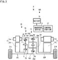
- the torque vectoring device 20 according to the second embodiment will be explained with reference to Fig. 3 , particularly, the points which differ from the torque vectoring device 10 of the first embodiment will be explained.
- the torque vectoring device 20 according to the second embodiment includes a single pinion planetary gear mechanism 19, a differential 13 and a torque vectoring motor 2.
- the single pinion planetary gear mechanism 19 and the differential 13 are provided adjacently, and are arranged coaxially with each other in series in an axial direction.
- the single pinion planetary gear mechanism 19 is formed by a sun gear S, a plurality of planetary gears P, a carrier C and a ring gear R.
- the sun gear S is connected to the torque vectoring rotor 2b of the torque vectoring motor 2.
- the plurality of planetary gears P is provided at the outer peripheral side of the sun gear S and is engaged with the sun gear S.
- the carrier C pivotally supports the plurality of planetary gears P.
- the ring gear R is provided at the outer peripheral side of the plurality of planetary gears P.
- the inner gear Ra which engages with the plurality of planetary gears P is formed at the inner periphery of the ring gear R.
- the differential 13 is structured as same with the structure of the differential 13 of the torque vectoring device 10 according to the first embodiment.
- the differential carrier Cd and the ring gear R are mutually connected with each other.
- the differential sun gear Sd and the sun gear S are mutually connected with each other.
- Fig. 4 The vertical axis in Fig. 4 indicates the rotational speed of respective elements shown in Fig. 3 .
- the area above the line zero (0) indicates the positive rotation direction. Signs and symbols in Fig. 4 represent the following:
- the straight line L2 represents the relationship of rotational speed of the sun gear S, carrier C and the ring gear R and the relationship of rotational speed of the differential sun gear Sd, the differential ring gear Rd and the differential carrier Cd.
- the solid line represents the state that the vehicle V is travelling straight forward, and the broken lines represents the state that a rotational speed difference is generated between the right and left drive wheels 21R and 21L by the torque vectoring device 20.
- the torque vectoring motor 2 rotates even under the state that the vehicle V is travelling straight forward. If a motor torque difference between the right drive wheel 21R and the left drive wheel 21L is required, the control portion 17 gives instructions to the inverter device 15 to have the torque Tmt of the torque vectoring motor 2 increase or decrease. Then, the inclination of the straight line L2 changes (See broken lines in Fig. 4 ) and the rotational speed N21 L of the left drive wheel 21 L and the rotational speed N21 R of the right drive wheel 21R are changed.
- torque vectoring motor 2 rotates. Accordingly, when the torque vectoring motor 2 is controlled such that the motor torques Tm outputted from the right and left drive wheels 21R and 21R from the drive motor generator 1 under the state that the vehicle V is travelling straight forward become equal to each other, the torque vectoring motor 2 is not rotated. Thus, flowing of the electric current only through the particular phase torque vectoring stator 2a among the torque vectoring stators 2a of the torque vectoring motor 2 can be prevented. As a result, the deterioration of the particular phase torque vectoring stator 2a can be prevented.
- the torque vectoring device 10 includes a torque vectoring motor 2, a first sun gear S1, a plurality of first planetary gears P1 provided at an outer peripheral side of the first sun gear S1 and engaged therewith, a second sun gear S2 which gear diameter is larger than a gear diameter of the first sun gear S1, a plurality of second planetary gears P2 provided at an outer peripheral side of the second sun gear S2 and engaged therewith, the plurality of second planetary gears P2 being arranged coaxial with the plurality of first planetary gears P1 and formed integrally therewith, a common carrier Cc connected to the torque vectoring motor 2 and pivotally supporting the plurality of first planetary gears P1 and the plurality of second planetary gears P2, and a differential 13 which includes a differential ring gear Rd (input member) to which a motor torque Tm (drive torque) is inputted, a differential sun gear Sd (first output member) connected to the first sun gear S1 and at the same time connected to a left drive wheel 21
- the torque vectoring device 10 of the first embodiment By structuring a torque vectoring device as defined above, according to the torque vectoring device 10 of the first embodiment, in the speed diagram shown in Fig. 2 , the distance between the vertical line which indicates the rotational speed Nmt of the torque vectoring motor 2 and the vertical line which indicates the rotational speed Nmd of the drive motor generator 1 becomes large. Therefore, the straight line L1 shown in Fig. 2 changes the inclination at the point of rotational speed Nmd of the drive motor generator 1 as a fulcrum point (See broken lines in Fig. 2 ). Thus, as the principle of leverage, the difference of the motor torques (drive torques) inputted to the right and left drive wheels 21R and 21L can be largely set.
- the torque vectoring device 20 includes a torque vectoring motor 2, a sun gear S to which the torque vectoring motor 2 is connected, a plurality of planetary gears P provided at an outer peripheral side of the sun gear S and engaged therewith, a carrier C pivotally supporting the plurality of planetary gears P, a ring gear R provided at an outer peripheral side of the plurality of planetary gears P and engaged therewith, and a differential 13 which includes a ring gear R (an input member) to which a motor torque (drive torque) is inputted, a differential sun gear Sd (first output member) connected to the carrier C and at the same time connected to a left drive wheel 21L and a differential carrier Cd (second output member) to which the ring gear R is connected and at the same time connected to a right drive wheel 21R, wherein the differential 13 absorbs a rotational speed difference between the right and left drive wheels 21R and 21L.
- the torque vectoring device 20 is formed only by the single pinion planetary gear mechanism 19 other than the differential 13. Therefore, comparing the structure which is formed by a plurality of planetary gear mechanisms other than the differential 13, the size in the axial direction of the torque vectoring device 20 according to the second embodiment can be down-sized.
- the differential 13 is a double pinion type planetary gear mechanism which includes a differential sun gear Sd, a plurality of first differential planetary gears Pd1 provided at an outer peripheral side of the differential sun gear Sd and engaged therewith, a plurality of second differential planetary gears Pd2 provided at an outer peripheral side of the plurality of first differential planetary gears Pd1 and engaged therewith, a differential carrier Cd which pivotally supports the plurality of first differential planetary gears Pd1 and the plurality of second differential planetary gears Pd2 and a differential ring gear Rd which is provided at an outer peripheral side of the plurality of second differential planetary gears Pd2 and engaged therewith.
- the drive source which outputs the drive torque to the differential ring gear Rd of the differential 13 is the drive motor generator 1.
- an engine may be used as the drive source which outputs the drive torque to the differential ring gear Rd.
- the drive motor generator 1 and the torque vectoring motor 2 have the electricity generation function (generator function), however, the motors without such generation function may be used, without any problems.
- the differential sun gear Sd is rotatably connected to one (the left drive wheel 21L) of the drive wheels 21R and 21L through the left drive axle 22L and the differential carrier Cd is rotatably connected to the other (the right drive wheel 21R) of the drive wheels 21R and 21L through the right drive axle 22R.
- the differential sun gear Sd is rotatably connected to one (the right drive wheel 21R) of the drive wheels 21R and 21L through the right drive axle 22R and the differential carrier Cd is rotatably connected to the other (the left drive wheel 21L) of the drive wheels 21R and 21L through the left drive axle 22L.
- the differential 13 is a double pinion type planetary gear mechanism. However, a bevel gear wheels are used for the differential 13.
Landscapes
- Engineering & Computer Science (AREA)
- General Engineering & Computer Science (AREA)
- Mechanical Engineering (AREA)
- Chemical & Material Sciences (AREA)
- Combustion & Propulsion (AREA)
- Transportation (AREA)
- Retarders (AREA)
- Electric Propulsion And Braking For Vehicles (AREA)
Applications Claiming Priority (2)
| Application Number | Priority Date | Filing Date | Title |
|---|---|---|---|
| JP2015177571A JP6447430B2 (ja) | 2015-09-09 | 2015-09-09 | トルクベクタリング装置 |
| PCT/JP2016/075371 WO2017043377A1 (ja) | 2015-09-09 | 2016-08-30 | トルクベクタリング装置 |
Publications (3)
| Publication Number | Publication Date |
|---|---|
| EP3348867A1 true EP3348867A1 (de) | 2018-07-18 |
| EP3348867A4 EP3348867A4 (de) | 2018-09-12 |
| EP3348867B1 EP3348867B1 (de) | 2019-12-04 |
Family
ID=58240760
Family Applications (1)
| Application Number | Title | Priority Date | Filing Date |
|---|---|---|---|
| EP16844238.2A Active EP3348867B1 (de) | 2015-09-09 | 2016-08-30 | Drehmomentvektorisierungsvorrichtung |
Country Status (5)
| Country | Link |
|---|---|
| US (1) | US10596895B2 (de) |
| EP (1) | EP3348867B1 (de) |
| JP (1) | JP6447430B2 (de) |
| CN (1) | CN107923509A (de) |
| WO (1) | WO2017043377A1 (de) |
Cited By (8)
| Publication number | Priority date | Publication date | Assignee | Title |
|---|---|---|---|---|
| US20180306298A1 (en) * | 2015-11-24 | 2018-10-25 | Schaeffler Technologies AG & Co. KG | Drive system for a motor vehicle |
| SE2150342A1 (en) * | 2021-03-24 | 2022-09-25 | Borgwarner Sweden Ab | Electric drive module |
| DE102022000324A1 (de) | 2022-01-27 | 2023-01-05 | Mercedes-Benz Group AG | Elektrische Antriebsvorrichtung für ein Kraftfahrzeug, insbesondere für einen Kraftwagen |
| DE102022000466A1 (de) | 2022-02-07 | 2023-03-09 | Mercedes-Benz Group AG | Elektrische Antriebseinheit für ein Kraftfahrzeug, insbesondere für einen Kraftwagen |
| DE102022000462B3 (de) | 2022-02-07 | 2023-03-16 | Mercedes-Benz Group AG | Elektrische Antriebseinheit für ein Kraftfahrzeug mit wählbarer Boost- oder Torque-Vectoring- Funktion |
| DE102022000463B3 (de) | 2022-02-07 | 2023-03-16 | Mercedes-Benz Group AG | Elektrische Antriebseinheit für ein Kraftfahrzeug mit wählbarer Boost- oder Torque-Vectoring- Funktion |
| DE102022000042B3 (de) | 2022-01-03 | 2023-04-13 | Mercedes-Benz Group AG | Elektrische Antriebsvorrichtung für ein Kraftfahrzeug, insbesondere für einen Kraftwagen |
| DE102022000037B3 (de) | 2022-01-03 | 2023-04-13 | Mercedes-Benz Group AG | Elektrische Antriebsvorrichtung für ein Kraftfahrzeug mit einem Torque- Vectoring-Getriebe |
Families Citing this family (25)
| Publication number | Priority date | Publication date | Assignee | Title |
|---|---|---|---|---|
| DE102017220167B3 (de) * | 2017-11-13 | 2019-03-21 | Audi Ag | Antriebsvorrichtung für eine Fahrzeugachse eines zweispurigen Fahrzeugs |
| JP6571157B2 (ja) * | 2017-12-25 | 2019-09-04 | 本田技研工業株式会社 | 動力配分装置 |
| KR102600054B1 (ko) * | 2018-07-10 | 2023-11-07 | 현대자동차 주식회사 | 토크 벡터링 장치 |
| KR102654449B1 (ko) * | 2018-12-05 | 2024-04-03 | 현대자동차 주식회사 | 토크 벡터링 장치 |
| KR102654446B1 (ko) * | 2018-12-05 | 2024-04-03 | 현대자동차 주식회사 | 토크 벡터링 장치 |
| KR102654456B1 (ko) * | 2018-12-18 | 2024-04-03 | 현대자동차 주식회사 | 토크 벡터링 장치 |
| KR102654454B1 (ko) * | 2018-12-18 | 2024-04-03 | 현대자동차 주식회사 | 토크 벡터링 장치 |
| KR102654455B1 (ko) * | 2018-12-18 | 2024-04-03 | 현대자동차 주식회사 | 토크 벡터링 장치 |
| US10982745B2 (en) * | 2019-01-15 | 2021-04-20 | GM Global Technology Operations LLC | Planetary differential drive system |
| DE112019007044T5 (de) * | 2019-03-19 | 2021-12-30 | Schaeffler Technologies AG & Co. KG | Torque-vectoring-system für nabenmotor-antriebssystem |
| DE102019209461A1 (de) * | 2019-06-28 | 2020-12-31 | Zf Friedrichshafen Ag | Getriebe mit einer Torque-Vectoring-Überlagerungseinheit |
| JP2021038785A (ja) * | 2019-09-03 | 2021-03-11 | トヨタ自動車株式会社 | トルクベクタリング装置 |
| KR102715815B1 (ko) * | 2019-09-24 | 2024-10-11 | 현대자동차 주식회사 | 토크 벡터링 장치 |
| KR102829607B1 (ko) * | 2020-01-08 | 2025-07-04 | 현대자동차 주식회사 | 토크 벡터링 장치 |
| EP3879134B1 (de) | 2020-03-13 | 2023-11-15 | Volvo Car Corporation | Getriebe mit torque vectoring |
| JP7251506B2 (ja) * | 2020-03-24 | 2023-04-04 | トヨタ自動車株式会社 | トルクベクタリング装置 |
| DE102021004236A1 (de) | 2021-08-19 | 2023-02-23 | Mercedes-Benz Group AG | Elektrisches Antriebssystem für ein Kraftfahrzeug |
| DE102021004237B4 (de) | 2021-08-19 | 2024-03-28 | Mercedes-Benz Group AG | Elektrisches Antriebssystem für ein Kraftfahrzeug |
| DE102021006118B3 (de) | 2021-12-13 | 2023-03-16 | Mercedes-Benz Group AG | Elektrisches Antriebssystem für ein Kraftfahrzeug mit zwei Elektromotoren und schaltbarer Torque- Vectoring-Funktion |
| CN114393991A (zh) * | 2022-02-23 | 2022-04-26 | 浙江吉利控股集团有限公司 | 变速器和车辆 |
| KR20230134021A (ko) * | 2022-03-10 | 2023-09-20 | 현대자동차주식회사 | 토크 벡터링 제어 장치 및 그 방법 |
| DE102023001052B3 (de) | 2023-03-17 | 2024-05-02 | Mercedes-Benz Group AG | Elektrisches Antriebssystem für ein Kraftfahrzeug |
| KR20250084641A (ko) | 2023-12-04 | 2025-06-11 | 현대자동차주식회사 | 전기자동차용 구동장치 |
| CN118544786A (zh) * | 2024-06-03 | 2024-08-27 | 中国第一汽车股份有限公司 | 一种驱动装置及车辆 |
| CN119393490A (zh) * | 2024-11-14 | 2025-02-07 | 麦格纳动力总成(江西)有限公司 | 一种传动装置、驱动系统和车辆 |
Family Cites Families (8)
| Publication number | Priority date | Publication date | Assignee | Title |
|---|---|---|---|---|
| JP2687052B2 (ja) | 1991-04-19 | 1997-12-08 | 本田技研工業株式会社 | 差動装置のトルク分配機構 |
| JPH05169991A (ja) * | 1992-03-19 | 1993-07-09 | Aisin Aw Co Ltd | 電気自動車用駆動装置 |
| JP3292120B2 (ja) * | 1997-12-10 | 2002-06-17 | 日産自動車株式会社 | 車両の走行アシスト装置 |
| JP2008513713A (ja) * | 2004-09-15 | 2008-05-01 | マグナ・シユタイル・フアールツオイクテヒニク・アクチエンゲゼルシヤフト・ウント・コンパニー・コマンデイトゲゼルシヤフト | トルク及び回転数の分配を制御可能な差動歯車構成体 |
| DE102006031089A1 (de) * | 2006-07-05 | 2008-01-17 | Fzgmbh | Antriebsvorrichtung für ein Kraftfahrzeug |
| EP2416033B1 (de) | 2009-03-31 | 2018-09-19 | Honda Motor Co., Ltd. | Antriebsvorrichtung und fahrzeug damit |
| US9248732B2 (en) * | 2011-11-02 | 2016-02-02 | Honda Motor Co., Ltd. | Power plant |
| DE102012212268B4 (de) * | 2012-07-13 | 2021-02-18 | Schaeffler Technologies AG & Co. KG | Antriebssystem für eine Elektrische Achse mit Zwei-Gang-Getriebe |
-
2015
- 2015-09-09 JP JP2015177571A patent/JP6447430B2/ja not_active Expired - Fee Related
-
2016
- 2016-08-30 EP EP16844238.2A patent/EP3348867B1/de active Active
- 2016-08-30 US US15/745,833 patent/US10596895B2/en active Active
- 2016-08-30 CN CN201680045864.2A patent/CN107923509A/zh active Pending
- 2016-08-30 WO PCT/JP2016/075371 patent/WO2017043377A1/ja not_active Ceased
Cited By (16)
| Publication number | Priority date | Publication date | Assignee | Title |
|---|---|---|---|---|
| US20180306298A1 (en) * | 2015-11-24 | 2018-10-25 | Schaeffler Technologies AG & Co. KG | Drive system for a motor vehicle |
| US10641375B2 (en) * | 2015-11-24 | 2020-05-05 | Schaeffler Technologies AG & Co. KG | Drive system for a motor vehicle |
| SE2150342A1 (en) * | 2021-03-24 | 2022-09-25 | Borgwarner Sweden Ab | Electric drive module |
| SE546763C2 (en) * | 2021-03-24 | 2025-02-18 | Borgwarner Sweden Ab | Electric drive module |
| DE102022000037B3 (de) | 2022-01-03 | 2023-04-13 | Mercedes-Benz Group AG | Elektrische Antriebsvorrichtung für ein Kraftfahrzeug mit einem Torque- Vectoring-Getriebe |
| DE102022000042B3 (de) | 2022-01-03 | 2023-04-13 | Mercedes-Benz Group AG | Elektrische Antriebsvorrichtung für ein Kraftfahrzeug, insbesondere für einen Kraftwagen |
| WO2023126183A1 (de) | 2022-01-03 | 2023-07-06 | Mercedes-Benz Group AG | Elektrische antriebsvorrichtung für ein kraftfahrzeug, insbesondere für einen kraftwagen |
| US12253152B2 (en) | 2022-01-03 | 2025-03-18 | Mercedes-Benz Group AG | Electric drive device for a motor vehicle, in particular for a motor car |
| DE102022000324A1 (de) | 2022-01-27 | 2023-01-05 | Mercedes-Benz Group AG | Elektrische Antriebsvorrichtung für ein Kraftfahrzeug, insbesondere für einen Kraftwagen |
| DE102022000462B3 (de) | 2022-02-07 | 2023-03-16 | Mercedes-Benz Group AG | Elektrische Antriebseinheit für ein Kraftfahrzeug mit wählbarer Boost- oder Torque-Vectoring- Funktion |
| DE102022000463B3 (de) | 2022-02-07 | 2023-03-16 | Mercedes-Benz Group AG | Elektrische Antriebseinheit für ein Kraftfahrzeug mit wählbarer Boost- oder Torque-Vectoring- Funktion |
| DE102022000466A1 (de) | 2022-02-07 | 2023-03-09 | Mercedes-Benz Group AG | Elektrische Antriebseinheit für ein Kraftfahrzeug, insbesondere für einen Kraftwagen |
| WO2023148325A1 (de) | 2022-02-07 | 2023-08-10 | Mercedes-Benz Group AG | Elektrische antriebseinheit für ein kraftfahrzeug, insbesondere für einen kraftwagen |
| WO2023148327A1 (de) | 2022-02-07 | 2023-08-10 | Mercedes-Benz Group AG | Elektrische antriebseinheit für ein kraftfahrzeug, insbesondere für einen kraftwagen |
| US12305738B1 (en) | 2022-02-07 | 2025-05-20 | Mercedes-Benz Group AG | Electric drive unit for a motor vehicle |
| US12311756B1 (en) | 2022-02-07 | 2025-05-27 | Mercedes-Benz Group AG | Electric drive unit for a motor vehicle, in particular for a motor car |
Also Published As
| Publication number | Publication date |
|---|---|
| EP3348867A4 (de) | 2018-09-12 |
| CN107923509A (zh) | 2018-04-17 |
| WO2017043377A1 (ja) | 2017-03-16 |
| US10596895B2 (en) | 2020-03-24 |
| US20180208048A1 (en) | 2018-07-26 |
| JP2017053430A (ja) | 2017-03-16 |
| EP3348867B1 (de) | 2019-12-04 |
| JP6447430B2 (ja) | 2019-01-09 |
Similar Documents
| Publication | Publication Date | Title |
|---|---|---|
| EP3348867B1 (de) | Drehmomentvektorisierungsvorrichtung | |
| US9950607B2 (en) | Powertrain with multi-planetary, single motor drive unit | |
| EP2775171B1 (de) | Antriebsaggregat | |
| US11370407B2 (en) | Power apparatus | |
| EP2738029A1 (de) | Antriebsvorrichtung für ein hybridfahrzeug | |
| US9334942B2 (en) | Drive torque distribution apparatus | |
| EP2554447B1 (de) | Antriebssteuerungsvorrichtung für ein hybridfahrzeug | |
| WO2014013408A4 (en) | A dual-structured electric drive and power system for hybrid vehicles | |
| US9077227B2 (en) | Electric motor assembly with electric phasing of rotor segments to reduce back electromotive force | |
| JP6519723B1 (ja) | 電動車両駆動装置 | |
| JP2008012992A (ja) | ハイブリッド車両の駆動制御装置 | |
| JP5065223B2 (ja) | 車両制御システム | |
| KR101631779B1 (ko) | 차량용 구동 장치 | |
| CN116691311A (zh) | 用于风力发电机系统的制造方法和风力发电机系统 | |
| CN110997382B (zh) | 电动车辆驱动装置 | |
| JP2013096531A (ja) | 動力伝達装置 | |
| JP2013001181A (ja) | 車両のパワートレーン | |
| KR101284325B1 (ko) | 궤도형 하이브리드 전기차량의 동력전달장치 | |
| JP7196765B2 (ja) | ハイブリッド車 | |
| US12539747B2 (en) | Drive device for vehicle | |
| US20240198782A1 (en) | Vehicle | |
| JP2017226302A (ja) | 車両 | |
| CN110300688B (zh) | 车辆 | |
| JP2023152774A (ja) | 車両用駆動装置 | |
| JP2023079356A (ja) | ハイブリッド車両の駆動装置 |
Legal Events
| Date | Code | Title | Description |
|---|---|---|---|
| STAA | Information on the status of an ep patent application or granted ep patent |
Free format text: STATUS: THE INTERNATIONAL PUBLICATION HAS BEEN MADE |
|
| PUAI | Public reference made under article 153(3) epc to a published international application that has entered the european phase |
Free format text: ORIGINAL CODE: 0009012 |
|
| STAA | Information on the status of an ep patent application or granted ep patent |
Free format text: STATUS: REQUEST FOR EXAMINATION WAS MADE |
|
| 17P | Request for examination filed |
Effective date: 20180105 |
|
| AK | Designated contracting states |
Kind code of ref document: A1 Designated state(s): AL AT BE BG CH CY CZ DE DK EE ES FI FR GB GR HR HU IE IS IT LI LT LU LV MC MK MT NL NO PL PT RO RS SE SI SK SM TR |
|
| AX | Request for extension of the european patent |
Extension state: BA ME |
|
| A4 | Supplementary search report drawn up and despatched |
Effective date: 20180810 |
|
| RIC1 | Information provided on ipc code assigned before grant |
Ipc: F16H 48/36 20120101AFI20180806BHEP Ipc: F16H 48/11 20120101ALI20180806BHEP |
|
| DAV | Request for validation of the european patent (deleted) | ||
| DAX | Request for extension of the european patent (deleted) | ||
| GRAP | Despatch of communication of intention to grant a patent |
Free format text: ORIGINAL CODE: EPIDOSNIGR1 |
|
| STAA | Information on the status of an ep patent application or granted ep patent |
Free format text: STATUS: GRANT OF PATENT IS INTENDED |
|
| INTG | Intention to grant announced |
Effective date: 20190722 |
|
| GRAJ | Information related to disapproval of communication of intention to grant by the applicant or resumption of examination proceedings by the epo deleted |
Free format text: ORIGINAL CODE: EPIDOSDIGR1 |
|
| GRAL | Information related to payment of fee for publishing/printing deleted |
Free format text: ORIGINAL CODE: EPIDOSDIGR3 |
|
| GRAS | Grant fee paid |
Free format text: ORIGINAL CODE: EPIDOSNIGR3 |
|
| STAA | Information on the status of an ep patent application or granted ep patent |
Free format text: STATUS: REQUEST FOR EXAMINATION WAS MADE |
|
| GRAR | Information related to intention to grant a patent recorded |
Free format text: ORIGINAL CODE: EPIDOSNIGR71 |
|
| STAA | Information on the status of an ep patent application or granted ep patent |
Free format text: STATUS: GRANT OF PATENT IS INTENDED |
|
| GRAA | (expected) grant |
Free format text: ORIGINAL CODE: 0009210 |
|
| STAA | Information on the status of an ep patent application or granted ep patent |
Free format text: STATUS: THE PATENT HAS BEEN GRANTED |
|
| INTC | Intention to grant announced (deleted) | ||
| AK | Designated contracting states |
Kind code of ref document: B1 Designated state(s): AL AT BE BG CH CY CZ DE DK EE ES FI FR GB GR HR HU IE IS IT LI LT LU LV MC MK MT NL NO PL PT RO RS SE SI SK SM TR |
|
| INTG | Intention to grant announced |
Effective date: 20191028 |
|
| REG | Reference to a national code |
Ref country code: GB Ref legal event code: FG4D |
|
| REG | Reference to a national code |
Ref country code: CH Ref legal event code: EP |
|
| REG | Reference to a national code |
Ref country code: AT Ref legal event code: REF Ref document number: 1209817 Country of ref document: AT Kind code of ref document: T Effective date: 20191215 |
|
| REG | Reference to a national code |
Ref country code: DE Ref legal event code: R096 Ref document number: 602016025808 Country of ref document: DE |
|
| REG | Reference to a national code |
Ref country code: IE Ref legal event code: FG4D |
|
| REG | Reference to a national code |
Ref country code: NL Ref legal event code: MP Effective date: 20191204 |
|
| REG | Reference to a national code |
Ref country code: LT Ref legal event code: MG4D |
|
| PG25 | Lapsed in a contracting state [announced via postgrant information from national office to epo] |
Ref country code: LV Free format text: LAPSE BECAUSE OF FAILURE TO SUBMIT A TRANSLATION OF THE DESCRIPTION OR TO PAY THE FEE WITHIN THE PRESCRIBED TIME-LIMIT Effective date: 20191204 Ref country code: SE Free format text: LAPSE BECAUSE OF FAILURE TO SUBMIT A TRANSLATION OF THE DESCRIPTION OR TO PAY THE FEE WITHIN THE PRESCRIBED TIME-LIMIT Effective date: 20191204 Ref country code: LT Free format text: LAPSE BECAUSE OF FAILURE TO SUBMIT A TRANSLATION OF THE DESCRIPTION OR TO PAY THE FEE WITHIN THE PRESCRIBED TIME-LIMIT Effective date: 20191204 Ref country code: NO Free format text: LAPSE BECAUSE OF FAILURE TO SUBMIT A TRANSLATION OF THE DESCRIPTION OR TO PAY THE FEE WITHIN THE PRESCRIBED TIME-LIMIT Effective date: 20200304 Ref country code: GR Free format text: LAPSE BECAUSE OF FAILURE TO SUBMIT A TRANSLATION OF THE DESCRIPTION OR TO PAY THE FEE WITHIN THE PRESCRIBED TIME-LIMIT Effective date: 20200305 Ref country code: BG Free format text: LAPSE BECAUSE OF FAILURE TO SUBMIT A TRANSLATION OF THE DESCRIPTION OR TO PAY THE FEE WITHIN THE PRESCRIBED TIME-LIMIT Effective date: 20200304 Ref country code: FI Free format text: LAPSE BECAUSE OF FAILURE TO SUBMIT A TRANSLATION OF THE DESCRIPTION OR TO PAY THE FEE WITHIN THE PRESCRIBED TIME-LIMIT Effective date: 20191204 |
|
| PG25 | Lapsed in a contracting state [announced via postgrant information from national office to epo] |
Ref country code: RS Free format text: LAPSE BECAUSE OF FAILURE TO SUBMIT A TRANSLATION OF THE DESCRIPTION OR TO PAY THE FEE WITHIN THE PRESCRIBED TIME-LIMIT Effective date: 20191204 Ref country code: HR Free format text: LAPSE BECAUSE OF FAILURE TO SUBMIT A TRANSLATION OF THE DESCRIPTION OR TO PAY THE FEE WITHIN THE PRESCRIBED TIME-LIMIT Effective date: 20191204 |
|
| PG25 | Lapsed in a contracting state [announced via postgrant information from national office to epo] |
Ref country code: AL Free format text: LAPSE BECAUSE OF FAILURE TO SUBMIT A TRANSLATION OF THE DESCRIPTION OR TO PAY THE FEE WITHIN THE PRESCRIBED TIME-LIMIT Effective date: 20191204 |
|
| PG25 | Lapsed in a contracting state [announced via postgrant information from national office to epo] |
Ref country code: RO Free format text: LAPSE BECAUSE OF FAILURE TO SUBMIT A TRANSLATION OF THE DESCRIPTION OR TO PAY THE FEE WITHIN THE PRESCRIBED TIME-LIMIT Effective date: 20191204 Ref country code: PT Free format text: LAPSE BECAUSE OF FAILURE TO SUBMIT A TRANSLATION OF THE DESCRIPTION OR TO PAY THE FEE WITHIN THE PRESCRIBED TIME-LIMIT Effective date: 20200429 Ref country code: EE Free format text: LAPSE BECAUSE OF FAILURE TO SUBMIT A TRANSLATION OF THE DESCRIPTION OR TO PAY THE FEE WITHIN THE PRESCRIBED TIME-LIMIT Effective date: 20191204 Ref country code: ES Free format text: LAPSE BECAUSE OF FAILURE TO SUBMIT A TRANSLATION OF THE DESCRIPTION OR TO PAY THE FEE WITHIN THE PRESCRIBED TIME-LIMIT Effective date: 20191204 Ref country code: NL Free format text: LAPSE BECAUSE OF FAILURE TO SUBMIT A TRANSLATION OF THE DESCRIPTION OR TO PAY THE FEE WITHIN THE PRESCRIBED TIME-LIMIT Effective date: 20191204 Ref country code: CZ Free format text: LAPSE BECAUSE OF FAILURE TO SUBMIT A TRANSLATION OF THE DESCRIPTION OR TO PAY THE FEE WITHIN THE PRESCRIBED TIME-LIMIT Effective date: 20191204 |
|
| PG25 | Lapsed in a contracting state [announced via postgrant information from national office to epo] |
Ref country code: SK Free format text: LAPSE BECAUSE OF FAILURE TO SUBMIT A TRANSLATION OF THE DESCRIPTION OR TO PAY THE FEE WITHIN THE PRESCRIBED TIME-LIMIT Effective date: 20191204 Ref country code: IS Free format text: LAPSE BECAUSE OF FAILURE TO SUBMIT A TRANSLATION OF THE DESCRIPTION OR TO PAY THE FEE WITHIN THE PRESCRIBED TIME-LIMIT Effective date: 20200404 Ref country code: SM Free format text: LAPSE BECAUSE OF FAILURE TO SUBMIT A TRANSLATION OF THE DESCRIPTION OR TO PAY THE FEE WITHIN THE PRESCRIBED TIME-LIMIT Effective date: 20191204 |
|
| REG | Reference to a national code |
Ref country code: DE Ref legal event code: R097 Ref document number: 602016025808 Country of ref document: DE |
|
| REG | Reference to a national code |
Ref country code: AT Ref legal event code: MK05 Ref document number: 1209817 Country of ref document: AT Kind code of ref document: T Effective date: 20191204 |
|
| PLBE | No opposition filed within time limit |
Free format text: ORIGINAL CODE: 0009261 |
|
| STAA | Information on the status of an ep patent application or granted ep patent |
Free format text: STATUS: NO OPPOSITION FILED WITHIN TIME LIMIT |
|
| PG25 | Lapsed in a contracting state [announced via postgrant information from national office to epo] |
Ref country code: DK Free format text: LAPSE BECAUSE OF FAILURE TO SUBMIT A TRANSLATION OF THE DESCRIPTION OR TO PAY THE FEE WITHIN THE PRESCRIBED TIME-LIMIT Effective date: 20191204 |
|
| 26N | No opposition filed |
Effective date: 20200907 |
|
| PG25 | Lapsed in a contracting state [announced via postgrant information from national office to epo] |
Ref country code: SI Free format text: LAPSE BECAUSE OF FAILURE TO SUBMIT A TRANSLATION OF THE DESCRIPTION OR TO PAY THE FEE WITHIN THE PRESCRIBED TIME-LIMIT Effective date: 20191204 Ref country code: PL Free format text: LAPSE BECAUSE OF FAILURE TO SUBMIT A TRANSLATION OF THE DESCRIPTION OR TO PAY THE FEE WITHIN THE PRESCRIBED TIME-LIMIT Effective date: 20191204 Ref country code: AT Free format text: LAPSE BECAUSE OF FAILURE TO SUBMIT A TRANSLATION OF THE DESCRIPTION OR TO PAY THE FEE WITHIN THE PRESCRIBED TIME-LIMIT Effective date: 20191204 |
|
| PG25 | Lapsed in a contracting state [announced via postgrant information from national office to epo] |
Ref country code: IT Free format text: LAPSE BECAUSE OF FAILURE TO SUBMIT A TRANSLATION OF THE DESCRIPTION OR TO PAY THE FEE WITHIN THE PRESCRIBED TIME-LIMIT Effective date: 20191204 |
|
| PG25 | Lapsed in a contracting state [announced via postgrant information from national office to epo] |
Ref country code: MC Free format text: LAPSE BECAUSE OF FAILURE TO SUBMIT A TRANSLATION OF THE DESCRIPTION OR TO PAY THE FEE WITHIN THE PRESCRIBED TIME-LIMIT Effective date: 20191204 |
|
| REG | Reference to a national code |
Ref country code: CH Ref legal event code: PL |
|
| GBPC | Gb: european patent ceased through non-payment of renewal fee |
Effective date: 20200830 |
|
| PG25 | Lapsed in a contracting state [announced via postgrant information from national office to epo] |
Ref country code: CH Free format text: LAPSE BECAUSE OF NON-PAYMENT OF DUE FEES Effective date: 20200831 Ref country code: LU Free format text: LAPSE BECAUSE OF NON-PAYMENT OF DUE FEES Effective date: 20200830 Ref country code: LI Free format text: LAPSE BECAUSE OF NON-PAYMENT OF DUE FEES Effective date: 20200831 |
|
| REG | Reference to a national code |
Ref country code: BE Ref legal event code: MM Effective date: 20200831 |
|
| PG25 | Lapsed in a contracting state [announced via postgrant information from national office to epo] |
Ref country code: FR Free format text: LAPSE BECAUSE OF NON-PAYMENT OF DUE FEES Effective date: 20200831 |
|
| PG25 | Lapsed in a contracting state [announced via postgrant information from national office to epo] |
Ref country code: GB Free format text: LAPSE BECAUSE OF NON-PAYMENT OF DUE FEES Effective date: 20200830 Ref country code: IE Free format text: LAPSE BECAUSE OF NON-PAYMENT OF DUE FEES Effective date: 20200830 Ref country code: BE Free format text: LAPSE BECAUSE OF NON-PAYMENT OF DUE FEES Effective date: 20200831 |
|
| PG25 | Lapsed in a contracting state [announced via postgrant information from national office to epo] |
Ref country code: TR Free format text: LAPSE BECAUSE OF FAILURE TO SUBMIT A TRANSLATION OF THE DESCRIPTION OR TO PAY THE FEE WITHIN THE PRESCRIBED TIME-LIMIT Effective date: 20191204 Ref country code: MT Free format text: LAPSE BECAUSE OF FAILURE TO SUBMIT A TRANSLATION OF THE DESCRIPTION OR TO PAY THE FEE WITHIN THE PRESCRIBED TIME-LIMIT Effective date: 20191204 Ref country code: CY Free format text: LAPSE BECAUSE OF FAILURE TO SUBMIT A TRANSLATION OF THE DESCRIPTION OR TO PAY THE FEE WITHIN THE PRESCRIBED TIME-LIMIT Effective date: 20191204 |
|
| PG25 | Lapsed in a contracting state [announced via postgrant information from national office to epo] |
Ref country code: MK Free format text: LAPSE BECAUSE OF FAILURE TO SUBMIT A TRANSLATION OF THE DESCRIPTION OR TO PAY THE FEE WITHIN THE PRESCRIBED TIME-LIMIT Effective date: 20191204 |
|
| PGFP | Annual fee paid to national office [announced via postgrant information from national office to epo] |
Ref country code: DE Payment date: 20230705 Year of fee payment: 8 |
|
| REG | Reference to a national code |
Ref country code: DE Ref legal event code: R119 Ref document number: 602016025808 Country of ref document: DE |
|
| PG25 | Lapsed in a contracting state [announced via postgrant information from national office to epo] |
Ref country code: DE Free format text: LAPSE BECAUSE OF NON-PAYMENT OF DUE FEES Effective date: 20250301 |