EP3348882A1 - Matériau d'étanchéité et mécanisme d'étanchéité - Google Patents
Matériau d'étanchéité et mécanisme d'étanchéité Download PDFInfo
- Publication number
- EP3348882A1 EP3348882A1 EP16844250.7A EP16844250A EP3348882A1 EP 3348882 A1 EP3348882 A1 EP 3348882A1 EP 16844250 A EP16844250 A EP 16844250A EP 3348882 A1 EP3348882 A1 EP 3348882A1
- Authority
- EP
- European Patent Office
- Prior art keywords
- sealing material
- sealing
- shaft
- sliding layer
- layer
- Prior art date
- Legal status (The legal status is an assumption and is not a legal conclusion. Google has not performed a legal analysis and makes no representation as to the accuracy of the status listed.)
- Withdrawn
Links
- 239000003566 sealing material Substances 0.000 title claims abstract description 97
- 238000007789 sealing Methods 0.000 title claims abstract description 51
- 229920001971 elastomer Polymers 0.000 claims abstract description 44
- 239000012791 sliding layer Substances 0.000 claims abstract description 41
- 239000000806 elastomer Substances 0.000 claims abstract description 35
- 239000010410 layer Substances 0.000 claims abstract description 32
- 230000002093 peripheral effect Effects 0.000 claims abstract description 29
- 239000000835 fiber Substances 0.000 claims abstract description 26
- 239000000463 material Substances 0.000 claims description 26
- 239000004744 fabric Substances 0.000 claims description 19
- 238000003780 insertion Methods 0.000 claims description 16
- 230000037431 insertion Effects 0.000 claims description 16
- 238000005187 foaming Methods 0.000 claims description 6
- 239000004088 foaming agent Substances 0.000 description 9
- 239000005060 rubber Substances 0.000 description 9
- 229910052751 metal Inorganic materials 0.000 description 8
- 239000002184 metal Substances 0.000 description 8
- 238000000034 method Methods 0.000 description 6
- 239000004519 grease Substances 0.000 description 5
- 239000000843 powder Substances 0.000 description 5
- 239000003795 chemical substances by application Substances 0.000 description 4
- 230000000052 comparative effect Effects 0.000 description 4
- 230000006835 compression Effects 0.000 description 4
- 238000007906 compression Methods 0.000 description 4
- 230000002040 relaxant effect Effects 0.000 description 4
- 238000004804 winding Methods 0.000 description 4
- -1 acryl Chemical group 0.000 description 3
- 230000000694 effects Effects 0.000 description 3
- 239000002657 fibrous material Substances 0.000 description 3
- 238000010438 heat treatment Methods 0.000 description 3
- 238000004898 kneading Methods 0.000 description 3
- 238000004519 manufacturing process Methods 0.000 description 3
- 239000002994 raw material Substances 0.000 description 3
- 125000006850 spacer group Chemical group 0.000 description 3
- 238000004073 vulcanization Methods 0.000 description 3
- 229920002943 EPDM rubber Polymers 0.000 description 2
- 229920000181 Ethylene propylene rubber Polymers 0.000 description 2
- 229920000459 Nitrile rubber Polymers 0.000 description 2
- UIIMBOGNXHQVGW-UHFFFAOYSA-M Sodium bicarbonate Chemical compound [Na+].OC([O-])=O UIIMBOGNXHQVGW-UHFFFAOYSA-M 0.000 description 2
- 230000015572 biosynthetic process Effects 0.000 description 2
- 238000005520 cutting process Methods 0.000 description 2
- 229920006168 hydrated nitrile rubber Polymers 0.000 description 2
- 238000010191 image analysis Methods 0.000 description 2
- 229910044991 metal oxide Inorganic materials 0.000 description 2
- 150000004706 metal oxides Chemical class 0.000 description 2
- 229920000728 polyester Polymers 0.000 description 2
- 238000003825 pressing Methods 0.000 description 2
- 238000012545 processing Methods 0.000 description 2
- 239000012744 reinforcing agent Substances 0.000 description 2
- 238000010998 test method Methods 0.000 description 2
- 238000012360 testing method Methods 0.000 description 2
- XMNIXWIUMCBBBL-UHFFFAOYSA-N 2-(2-phenylpropan-2-ylperoxy)propan-2-ylbenzene Chemical compound C=1C=CC=CC=1C(C)(C)OOC(C)(C)C1=CC=CC=C1 XMNIXWIUMCBBBL-UHFFFAOYSA-N 0.000 description 1
- ATRRKUHOCOJYRX-UHFFFAOYSA-N Ammonium bicarbonate Chemical compound [NH4+].OC([O-])=O ATRRKUHOCOJYRX-UHFFFAOYSA-N 0.000 description 1
- 239000004156 Azodicarbonamide Substances 0.000 description 1
- OKTJSMMVPCPJKN-UHFFFAOYSA-N Carbon Chemical compound [C] OKTJSMMVPCPJKN-UHFFFAOYSA-N 0.000 description 1
- 229920000049 Carbon (fiber) Polymers 0.000 description 1
- 229920000742 Cotton Polymers 0.000 description 1
- MWRWFPQBGSZWNV-UHFFFAOYSA-N Dinitrosopentamethylenetetramine Chemical compound C1N2CN(N=O)CN1CN(N=O)C2 MWRWFPQBGSZWNV-UHFFFAOYSA-N 0.000 description 1
- JOYRKODLDBILNP-UHFFFAOYSA-N Ethyl urethane Chemical compound CCOC(N)=O JOYRKODLDBILNP-UHFFFAOYSA-N 0.000 description 1
- YCKRFDGAMUMZLT-UHFFFAOYSA-N Fluorine atom Chemical compound [F] YCKRFDGAMUMZLT-UHFFFAOYSA-N 0.000 description 1
- 244000043261 Hevea brasiliensis Species 0.000 description 1
- 229920000106 Liquid crystal polymer Polymers 0.000 description 1
- 239000004977 Liquid-crystal polymers (LCPs) Substances 0.000 description 1
- 239000004820 Pressure-sensitive adhesive Substances 0.000 description 1
- VYPSYNLAJGMNEJ-UHFFFAOYSA-N Silicium dioxide Chemical compound O=[Si]=O VYPSYNLAJGMNEJ-UHFFFAOYSA-N 0.000 description 1
- 235000021355 Stearic acid Nutrition 0.000 description 1
- 239000004809 Teflon Substances 0.000 description 1
- 229920006362 Teflon® Polymers 0.000 description 1
- 239000004433 Thermoplastic polyurethane Substances 0.000 description 1
- 238000009825 accumulation Methods 0.000 description 1
- 239000000654 additive Substances 0.000 description 1
- 239000000853 adhesive Substances 0.000 description 1
- 230000001070 adhesive effect Effects 0.000 description 1
- 239000001099 ammonium carbonate Substances 0.000 description 1
- 235000012501 ammonium carbonate Nutrition 0.000 description 1
- 230000003712 anti-aging effect Effects 0.000 description 1
- 229920006231 aramid fiber Polymers 0.000 description 1
- XOZUGNYVDXMRKW-AATRIKPKSA-N azodicarbonamide Chemical compound NC(=O)\N=N\C(N)=O XOZUGNYVDXMRKW-AATRIKPKSA-N 0.000 description 1
- 235000019399 azodicarbonamide Nutrition 0.000 description 1
- 239000006229 carbon black Substances 0.000 description 1
- 239000004917 carbon fiber Substances 0.000 description 1
- 229920006235 chlorinated polyethylene elastomer Polymers 0.000 description 1
- 238000004132 cross linking Methods 0.000 description 1
- 235000014113 dietary fatty acids Nutrition 0.000 description 1
- 239000000428 dust Substances 0.000 description 1
- 239000013013 elastic material Substances 0.000 description 1
- 238000011156 evaluation Methods 0.000 description 1
- 239000000194 fatty acid Substances 0.000 description 1
- 229930195729 fatty acid Natural products 0.000 description 1
- 150000004665 fatty acids Chemical class 0.000 description 1
- 239000000945 filler Substances 0.000 description 1
- 230000009969 flowable effect Effects 0.000 description 1
- 239000011737 fluorine Substances 0.000 description 1
- 229910052731 fluorine Inorganic materials 0.000 description 1
- 229920001973 fluoroelastomer Polymers 0.000 description 1
- 239000006260 foam Substances 0.000 description 1
- 239000003365 glass fiber Substances 0.000 description 1
- 229910002804 graphite Inorganic materials 0.000 description 1
- 239000010439 graphite Substances 0.000 description 1
- 229920002681 hypalon Polymers 0.000 description 1
- 239000007788 liquid Substances 0.000 description 1
- 239000000314 lubricant Substances 0.000 description 1
- 238000010077 mastication Methods 0.000 description 1
- 230000018984 mastication Effects 0.000 description 1
- VNWKTOKETHGBQD-UHFFFAOYSA-N methane Chemical compound C VNWKTOKETHGBQD-UHFFFAOYSA-N 0.000 description 1
- CWQXQMHSOZUFJS-UHFFFAOYSA-N molybdenum disulfide Chemical compound S=[Mo]=S CWQXQMHSOZUFJS-UHFFFAOYSA-N 0.000 description 1
- 229910052982 molybdenum disulfide Inorganic materials 0.000 description 1
- 238000000465 moulding Methods 0.000 description 1
- ALIFPGGMJDWMJH-UHFFFAOYSA-N n-phenyldiazenylaniline Chemical compound C=1C=CC=CC=1NN=NC1=CC=CC=C1 ALIFPGGMJDWMJH-UHFFFAOYSA-N 0.000 description 1
- 229920003052 natural elastomer Polymers 0.000 description 1
- 229920001194 natural rubber Polymers 0.000 description 1
- 239000004745 nonwoven fabric Substances 0.000 description 1
- 229920001778 nylon Polymers 0.000 description 1
- QIQXTHQIDYTFRH-UHFFFAOYSA-N octadecanoic acid Chemical compound CCCCCCCCCCCCCCCCCC(O)=O QIQXTHQIDYTFRH-UHFFFAOYSA-N 0.000 description 1
- OQCDKBAXFALNLD-UHFFFAOYSA-N octadecanoic acid Natural products CCCCCCCC(C)CCCCCCCCC(O)=O OQCDKBAXFALNLD-UHFFFAOYSA-N 0.000 description 1
- 150000001451 organic peroxides Chemical class 0.000 description 1
- 150000002898 organic sulfur compounds Chemical class 0.000 description 1
- 239000004014 plasticizer Substances 0.000 description 1
- 229920001084 poly(chloroprene) Polymers 0.000 description 1
- 229920002857 polybutadiene Polymers 0.000 description 1
- 229920002635 polyurethane Polymers 0.000 description 1
- 239000004814 polyurethane Substances 0.000 description 1
- 230000003014 reinforcing effect Effects 0.000 description 1
- 230000000452 restraining effect Effects 0.000 description 1
- 239000004065 semiconductor Substances 0.000 description 1
- 229920002545 silicone oil Polymers 0.000 description 1
- 229920002379 silicone rubber Polymers 0.000 description 1
- 239000004945 silicone rubber Substances 0.000 description 1
- 229910000030 sodium bicarbonate Inorganic materials 0.000 description 1
- 235000017557 sodium bicarbonate Nutrition 0.000 description 1
- 239000007787 solid Substances 0.000 description 1
- 239000002904 solvent Substances 0.000 description 1
- 239000008117 stearic acid Substances 0.000 description 1
- 229920003048 styrene butadiene rubber Polymers 0.000 description 1
- 229920001897 terpolymer Polymers 0.000 description 1
- 229920001169 thermoplastic Polymers 0.000 description 1
- 229920002803 thermoplastic polyurethane Polymers 0.000 description 1
- 229920001187 thermosetting polymer Polymers 0.000 description 1
- 239000004416 thermosoftening plastic Substances 0.000 description 1
- 239000011800 void material Substances 0.000 description 1
- 239000002759 woven fabric Substances 0.000 description 1
Images

Classifications
-
- F—MECHANICAL ENGINEERING; LIGHTING; HEATING; WEAPONS; BLASTING
- F16—ENGINEERING ELEMENTS AND UNITS; GENERAL MEASURES FOR PRODUCING AND MAINTAINING EFFECTIVE FUNCTIONING OF MACHINES OR INSTALLATIONS; THERMAL INSULATION IN GENERAL
- F16J—PISTONS; CYLINDERS; SEALINGS
- F16J15/00—Sealings
- F16J15/16—Sealings between relatively-moving surfaces
- F16J15/18—Sealings between relatively-moving surfaces with stuffing-boxes for elastic or plastic packings
- F16J15/20—Packing materials therefor
-
- G—PHYSICS
- G03—PHOTOGRAPHY; CINEMATOGRAPHY; ANALOGOUS TECHNIQUES USING WAVES OTHER THAN OPTICAL WAVES; ELECTROGRAPHY; HOLOGRAPHY
- G03G—ELECTROGRAPHY; ELECTROPHOTOGRAPHY; MAGNETOGRAPHY
- G03G15/00—Apparatus for electrographic processes using a charge pattern
-
- G—PHYSICS
- G03—PHOTOGRAPHY; CINEMATOGRAPHY; ANALOGOUS TECHNIQUES USING WAVES OTHER THAN OPTICAL WAVES; ELECTROGRAPHY; HOLOGRAPHY
- G03G—ELECTROGRAPHY; ELECTROPHOTOGRAPHY; MAGNETOGRAPHY
- G03G15/00—Apparatus for electrographic processes using a charge pattern
- G03G15/06—Apparatus for electrographic processes using a charge pattern for developing
- G03G15/08—Apparatus for electrographic processes using a charge pattern for developing using a solid developer, e.g. powder developer
-
- G—PHYSICS
- G03—PHOTOGRAPHY; CINEMATOGRAPHY; ANALOGOUS TECHNIQUES USING WAVES OTHER THAN OPTICAL WAVES; ELECTROGRAPHY; HOLOGRAPHY
- G03G—ELECTROGRAPHY; ELECTROPHOTOGRAPHY; MAGNETOGRAPHY
- G03G15/00—Apparatus for electrographic processes using a charge pattern
- G03G15/06—Apparatus for electrographic processes using a charge pattern for developing
- G03G15/08—Apparatus for electrographic processes using a charge pattern for developing using a solid developer, e.g. powder developer
- G03G15/0806—Apparatus for electrographic processes using a charge pattern for developing using a solid developer, e.g. powder developer on a donor element, e.g. belt, roller
- G03G15/0817—Apparatus for electrographic processes using a charge pattern for developing using a solid developer, e.g. powder developer on a donor element, e.g. belt, roller characterised by the lateral sealing at both sides of the donor member with respect to the developer carrying direction
-
- G—PHYSICS
- G03—PHOTOGRAPHY; CINEMATOGRAPHY; ANALOGOUS TECHNIQUES USING WAVES OTHER THAN OPTICAL WAVES; ELECTROGRAPHY; HOLOGRAPHY
- G03G—ELECTROGRAPHY; ELECTROPHOTOGRAPHY; MAGNETOGRAPHY
- G03G15/00—Apparatus for electrographic processes using a charge pattern
- G03G15/06—Apparatus for electrographic processes using a charge pattern for developing
- G03G15/08—Apparatus for electrographic processes using a charge pattern for developing using a solid developer, e.g. powder developer
- G03G15/0896—Arrangements or disposition of the complete developer unit or parts thereof not provided for by groups G03G15/08 - G03G15/0894
- G03G15/0898—Arrangements or disposition of the complete developer unit or parts thereof not provided for by groups G03G15/08 - G03G15/0894 for preventing toner scattering during operation, e.g. seals
-
- Y—GENERAL TAGGING OF NEW TECHNOLOGICAL DEVELOPMENTS; GENERAL TAGGING OF CROSS-SECTIONAL TECHNOLOGIES SPANNING OVER SEVERAL SECTIONS OF THE IPC; TECHNICAL SUBJECTS COVERED BY FORMER USPC CROSS-REFERENCE ART COLLECTIONS [XRACs] AND DIGESTS
- Y10—TECHNICAL SUBJECTS COVERED BY FORMER USPC
- Y10S—TECHNICAL SUBJECTS COVERED BY FORMER USPC CROSS-REFERENCE ART COLLECTIONS [XRACs] AND DIGESTS
- Y10S277/00—Seal for a joint or juncture
- Y10S277/935—Seal made of a particular material
- Y10S277/944—Elastomer or plastic
Definitions
- the present invention relates to a sealing material and a sealing mechanism for the purpose of preventing leakage and scattering of powder, such as toner.
- Patent Document 1 discloses a cylindrical sealing member formed by bringing a pile or fiber sheet into a cylindrical shape, and restraining an outer peripheral side thereof with a metal support member.
- the cylindrical sealing member keeps a balance between sliding resistance and sealing property by pressing, through the pile or fiber, the outer periphery of the shaft at an appropriate compression force.
- the cylindrical sealing member has the following problems. That is, the pile or fiber has low durability, and the sealing property is lowered due to accumulation of the powder between the piles or fibers.
- the sealing material is prone to deformation when a high pressure is applied from the outer periphery in order to enhance the sealing property. It is therefore difficult to apply to apparatuses used under high load over a long period of time.
- Patent Document 1 Japanese Unexamined Patent Publication No. 2008-26728
- the present invention aims at providing a highly durable sealing material having both low sliding resistance and high sealing property, as well as a sealing mechanism capable of relaxing an external compression force.
- a sealing material of the present invention is the sealing material for sealing between a hole of a structure and a shaft inserted into the hole.
- the sealing material includes a sliding layer and an elastic integument layer.
- the sliding layer has a ring shape or cylindrical shape whose inner peripheral surface slides with the shaft during movement of the shaft relative to the structure.
- the sliding layer has a fiber and an elastomer integrated with each other.
- the elastic integument layer is laminated on an outer peripheral surface of the sliding layer, and has a porous structure.
- the sealing material of the present invention is made up of the elastic material having, on the inner peripheral surface side, the sliding layer in which the fiber and the elastomer are integrated with each other. Therefore, the sealing material has high sealing property and excellent durability.
- the elastic integument layer disposed close to the outer peripheral surface of the sliding layer has the porous structure, it is possible to relax the external compressive force on the shaft, thereby achieving an appropriate sliding torque.
- FIG. 1 shows a sealing material 10 according to an embodiment of the present invention.
- the sealing material 10 has a ring shape, and has, at a middle part thereof, a shaft insertion hole 3 that permits insertion of a shaft 30.
- a sliding layer 11 and an elastic integument layer 12 are laminated in this order and integrated with each other around the shaft 30 toward an outer periphery thereof.
- the sealing material 10 is interposed between an inner peripheral surface of a sealing material accommodating recess 22 formed at an inlet of a hole 21 of a structure 20, namely, a shaft insertion port 51, and an outer peripheral surface of the shaft 30 inserted through the sealing material accommodating recess 22.
- the sealing material 10 seals the outer peripheral surface of the shaft 30 that makes rotational motion around its own axis or makes axial reciprocating motion.
- the shaft 30 is inserted through the sealing material accommodating recess 22 into the hole 21 of the structure 20.
- the sealing material accommodating recess 22 communicates with the hole 21, and has an inner diameter larger than a diameter of the hole 21.
- the sealing material 10 is suitably adjusted according to the shape and size of the shaft 30 described later, in order to ensure that a gap is less likely to occur between the inner peripheral surface of the shaft insertion hole 3 and the outer peripheral surface of the shaft 30 during operation of the shaft 30.
- the sliding layer 11 of the sealing material 10 is intended to seal the outer peripheral surface of the shaft 30 as shown in FIG. 1 .
- the sliding layer 11 is made up of fiber and an elastomer which are integrated with each other. This contributes to reducing sliding resistance of the shaft 30 subjected to contact, thereby leading to the sealing material with excellent durability against sliding friction.
- the elastomer constituting the sliding layer 11 is mainly intended to improve durability of the fiber.
- the material of the elastomer include elastomers, such as natural rubber, nitrile rubber, chloroprene rubber, hypalon, polybutadiene rubber, ethylene-propylene rubber (EPM), ethylene-propylene-diene rubber terpolymer (EPDM), hydrogenated acrylonitrile butadiene rubber (H-NBR), silicone rubber, fluoro rubber, acryl rubber, styrene butadiene rubber, chlorinated polyethylene rubber, millable urethane, thermosetting polyurethane, thermoplastic polyurethane, and thermoplastic polyester.
- elastomers such as natural rubber, nitrile rubber, chloroprene rubber, hypalon, polybutadiene rubber, ethylene-propylene rubber (EPM), ethylene-propylene-diene rubber terpolymer (EPDM), hydrogenated acrylonitrile butadiene
- a vulcanizing agent, a vulcanization accelerator, and a reinforcing agent may be blended with the elastomer constituting the sliding layer 11.
- the vulcanizing agent include organic peroxides, such as dicumyl peroxide, organic sulfur compounds, and metal oxides.
- the vulcanization accelerator include fatty acids, such as stearic acid, and metal oxide.
- the reinforcing agent include carbon black, and white carbon.
- an anti-aging agent, a filler, plasticizer, and pressure sensitive adhesive may be blended.
- a solid lubricating agent such as graphite, silicone oil, fluorine powder, and molybdenum disulfide, may be contained in the elastomer.
- the fiber constituting the sliding layer 11 is mainly intended to be brought into contact with and slides along the outer peripheral surface of the shaft 30, and the fiber becomes a main factor reducing the sliding resistance around the shaft 30.
- the material of the fiber constituting the sliding layer 11 examples include nylon fiber, aramid fiber, polyester fiber, carbon fiber, Teflon (registered trademark) fiber, liquid crystal polymer fiber, glass fiber, and cotton thread.
- the fiber constituting the sliding layer 11 may be in the form of a fabric material, or the fiber in the form of short fibers may be mixed with the elastomer.
- the fabric material include woven fabric, knitted fabric, and nonwoven fabric. Although a basis weight of the fabric material is usually 20-200 g/m 2 , no particular limitation is imposed thereon.
- the fiber form is a fabric material
- the fabric material and the elastomer are integrated with each other so that the fabric material is brought into sliding contact with the outer peripheral surface of the shaft 30.
- the sliding layer 11 is obtainable by mixing the short fibers into the elastomer, followed by integral formation.
- the elastic integument layer 12 has a porous structure.
- the elastic integument layer 12 is obtainable by incorporating, for example, a foaming agent into an elastomer material, followed by so-called foaming and crosslinking in which foaming occurs at the same time as vulcanization by heating under pressure.
- a foaming agent into an elastomer material, followed by so-called foaming and crosslinking in which foaming occurs at the same time as vulcanization by heating under pressure.
- an elastomer material used an elastomer material similar to that for the sliding layer 11 is usable. It is particularly preferable to use the same elastomer material as that for the sliding layer 11 for the purpose of being integrated with the sliding layer 11.
- any of ones which have been conventionally used for foaming of elastomers there are, for example, sodium hydrogen carbonate, ammonium carbonate, diazo amino benzene, N,N'-dinitroso pentamethylene tetramine, and azodicarbonamide.
- sodium hydrogen carbonate ammonium carbonate
- diazo amino benzene diazo amino benzene
- N,N'-dinitroso pentamethylene tetramine and azodicarbonamide.
- materials similar to those for the sliding layer 11 are usable.
- the hardness (rubber hardness) of the elastic integument layer 12 is 50-90 Hs, preferably approximately 60-70 Hs measured by type A durometer according to JIS K6253.
- the density of the elastic integument layer 12 is 1.0-1.4 kg/m3, preferably approximately 1.1-1.2 kg/m 3 .
- the addition amount of the foaming agent is 0.1-10% by mass, preferably 0.3-3.0% by mass relative to a total amount of the elastomer.
- a radial thickness of each of the sliding layer 11 and the elastic integument layer 12 The radial thickness needs to be suitably adjusted according to, for example, the purpose of use of the sealing material 10.
- a ratio of the radial thickness of the sliding layer 11 and the radial thickness of the elastic integument layer 12 having the porous structure is preferably 1:10 to 1:30 for the purpose of relaxing external compressive force exerted from the sealing material 10 lying along the outer periphery to the shaft 30.
- the sealing material 10 has a ring shape or cylindrical shape.
- a length of the sealing material 10 along an axial direction of the shaft 30 is not particularly limited, but the length usually needs approximately 0.5-10 mm.
- a shape of the shaft insertion hole 3 of the sealing material 10 is determined according to the shape of the shaft 30.
- a cross-sectional form of the shaft 30 may be, for example, a circle, square, or polygonal form.
- the shaft 30 may have a screw groove (not shown) formed on an outer surface thereof.
- an inner peripheral surface of the shaft insertion hole 3 of the sliding layer 11 is preferably provided with a screw groove being engageable with the screw groove of the shaft 30 for the purpose of ensuring sealing property.
- a method of manufacturing the sealing material 10 according to the present invention is not particularly limited.
- the method includes winding a fiber (fabric material) being impregnated with an elastomer for forming the sliding layer, around a bar-shaped object having a shape similar to the outer peripheral surface of the shaft 30, then winding, around an outer surface thereof, an elastomer for forming the elastic integument layer containing a foaming agent.
- the method further includes holding this between upper and lower metal molds capable of molding into a desired sealing material 10, followed by bonding by heating under pressure while simultaneously causing foaming of the elastomer for forming the elastic integument layer.
- the sealing material 10 is obtainable by taking a molded product out of the metal molds, and then cutting the molded product in a necessary thickness.
- the sealing material 10 is also manufacturable with a metal mold forming method. That is, a fabric material being impregnated with an elastomer for forming the sliding layer is wound around a bar-shaped object having a shape similar to the outer peripheral surface of the shaft 30. This is then held between metal molds. Subsequently, a flowable elastomer for forming the elastic integument layer containing a foaming agent is poured into the metal molds. This is heated under pressure and then taken out of the metal molds.
- the sliding layer 11 and the elastic integument layer 12 having the porous structure may be bonded to each other with an adhesive.
- the sealing material 10 is, for example, disposed and used as shown in FIG. 1 . Specifically, after the shaft 30 is inserted into the shaft insertion hole 3 at the middle part of the sealing material 10, the shaft 30 is inserted into the hole 21 of the structure 20, and the sealing material 10 is press-fitted into the sealing material accommodating recess 22 ahead of the hole 21. Subsequently, the sealing material 10 is sealed within the sealing material accommodating recess 22 by attaching the sealing retainer 24 to an outer surface of the structure 20.
- the sealing material 10 may be previously press-fitted into the sealing material accommodating recess 22, and the sealing retainer 24 may be attached thereto. Thereafter, the shaft 30 may be inserted into the hole 21 of the structure 20 through the shaft insertion hole 3 of the sealing material 10.
- the sealing retainer 24 is intended to be fixed to an outer wall surface of the structure 20 by a fastening screw (not shown) after the sealing material 10 externally inserted into the shaft 30 is press-fitted into the sealing material accommodating recess 22, and is attached thereto in a compressed state.
- the sealing retainer 24 is not particularly limited as long as it can confine the sealing material 10 in the sealing material accommodating recess 22 and can adhere to the structure 20.
- the sealing material 10 is fixed within the sealing material accommodating recess 22 by the sealing retainer 24, and the sealing material 10 does not separate from the structure 20 even when the shaft 30 is moved.
- the elastic integument layer 12 is a non-foaming body having no porous structure
- a pressing force from the sealing retainer 24 is dispersed in multiple directions in the elastic integument layer 12, and the elastic integument layer 12 is susceptible to appearance deformation.
- the elastic integument layer 12 has the porous structure as in the present embodiment
- when the sealing retainer 24 compresses the elastic integument layer 12 upon attachment void parts (not shown) in the porous structure included in the elastic integument layer 12 deform upon receipt of a pressure from the sealing retainer 24, thus contributing to relaxing an external compression force.
- the appearance of the elastic integument layer 12 is therefore less likely to be deformed.
- Spring effect of improving the porous structure inside the elastic integument layer 12 can be expected.
- the spring effect makes it possible to press the sliding layer 11 against the shaft 30 when an external pressure of a predetermined value or above is applied to the elastic integument layer 12. This leads to improved sealing property.
- a front surface of the sealing material 10, from which the foreign matter 4 may enter is formed vertical to the shaft 30 as shown in FIG. 1 .
- the front surface may be inclined into a slope shape so that an inner peripheral surface side of the sealing material 10 is located more outside the structure 20 than an outer peripheral surface side of the sealing material 10. This is effective in eliminating the foreign matter 4.
- FIG. 2 shows a sealing mechanism according to still another embodiment of the present invention.
- a sealing material 10 is fitted in a compressed state into a sealing material accommodating recess 43 disposed in a sealing retainer 42 located outside a structure 20 in the present embodiment.
- the sealing retainer 42 is attached to the outside of a shaft insertion port 52 disposed in the structure 20 in the present embodiment.
- the sealing material accommodating recess 43 is formed on a surface of the sealing retainer 42 which is opposed to the shaft insertion port 52.
- the shaft insertion port 52 is sealed by interposing the sealing material 10 between an inner peripheral surface of the sealing material accommodating recess 43 and an outer peripheral surface of the shaft 30 inserted into a hole 21 of the structure 20.
- the sealing retainer 42 causes the sealing material 10 externally inserted into the shaft 30 to be press-fitted into the sealing material accommodating recess 43 so as to be compressively deformed. Thereafter, the sealing retainer 42 is secured to an outer wall surface of the structure 20 by a fastening screw or the like. Others are common to the embodiment shown in FIG. 1 .
- the sealing material and the sealing mechanism of the present invention are suitably usable as a sealing material applied as shaft seal for a shaft, such as rotary shafts for use in, for example, vehicles, such as automobiles, motorbikes, bicycles, amusement vehicles, motorboats, railway vehicles, ships, aircrafts, and spaceships, industrial machines, such as various machines, machine tools, robots, as well as production facilities, image processing apparatuses, semiconductor manufacturing apparatuses, and chip mounters, each of which is easily affected by vibration.
- a shaft such as rotary shafts
- vehicles such as automobiles, motorbikes, bicycles, amusement vehicles, motorboats, railway vehicles, ships, aircrafts, and spaceships
- industrial machines such as various machines, machine tools, robots, as well as production facilities, image processing apparatuses, semiconductor manufacturing apparatuses, and chip mounters, each of which is easily affected by vibration.
- a base rubber (NBR rubber) was subjected to a primary kneading (mastication), and 0.55% by weight of DPT (dinitroso pentamethylene tetramin) was added as a foaming agent to a total amount of the base rubber. This was then subjected to a secondary kneading (kneading) to obtain a raw material rubber for a sealing material.
- NBR rubber a primary kneading
- DPT dinitroso pentamethylene tetramin
- a cylindrical sealing material was obtained by winding a canvas being impregnated with an elastomer around a bar-shaped object having the same shape as the outer peripheral surface of the shaft 30, and then winding therearound the raw material rubber containing the foaming agent, followed by heating under pressure so as to be fused to the canvas. Thereafter, the sealing material was obtainable by taking this out of metal molds, and then cutting this in a predetermined thickness. Hardness and density of the sealing material are presented in Table 1. The hardness was obtained by measuring the outer peripheral surface of the sealing material 10 with a rubber hardness tester.
- a sealing material was obtained in the same manner as in Example, except that no foaming agent was added to a raw material rubber. Hardness and density of the sealing material are presented in Table 1.
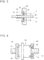
- a screw shaft 31 of a ball screw was inserted through the sealing material 10.
- the sealing material 10 was secured by mounting the sealing retainer 24 thereon and fastening a screw 26.
- a spacer 25 was disposed on an outer peripheral side in the sealing material accommodating recess 22, and an adjustment was made so that compressibility of the sealing material 10 reached 2%.
- a clearance T was left between the sealing material 10 and the spacer 25 in order to avoid compression in an outer peripheral direction.
- the sealing property was evaluated as follows. That is, a residual volume of the grease 27 on the screw shaft 31 was analyzed from an image taken by the image analysis camera. The evaluation was made that the sealing property was 100% when nothing remained. The results are presented in Table 1.
- the sealing material 10 was inserted through a screw shaft 31' of a ball screw, and was brought into contact with both surfaces of a structure 50 (corresponding to a nut). Sealing retainers 42, 42' were mounted from an outer surface of the sealing material 10. The sealing material 10 was secured by fastening the sealing retainer 42 by a screw 26 or the like. On this occasion, the sealing material 10 was in a state of being compressed 2% in a thickness direction without being compressed in an outer diameter direction.
- the sealing material of Example had hardness and density, each of which was lowered by approximately 5%, and the torque exerted on the shaft was also reduced by approximately 17% than that of a normal elastic body of Comparative Example. There was no significant difference in sealing property between Example and Comparative Example. This shows that the torque is reducible while maintaining sealing property.
Landscapes
- Engineering & Computer Science (AREA)
- General Engineering & Computer Science (AREA)
- Physics & Mathematics (AREA)
- General Physics & Mathematics (AREA)
- Mechanical Engineering (AREA)
- Sealing Devices (AREA)
- Dry Development In Electrophotography (AREA)
- Electrophotography Configuration And Component (AREA)
Applications Claiming Priority (2)
| Application Number | Priority Date | Filing Date | Title |
|---|---|---|---|
| JP2015177201A JP2017053418A (ja) | 2015-09-09 | 2015-09-09 | シール材およびシール機構 |
| PCT/JP2016/075501 WO2017043389A1 (fr) | 2015-09-09 | 2016-08-31 | Matériau d'étanchéité et mécanisme d'étanchéité |
Publications (2)
| Publication Number | Publication Date |
|---|---|
| EP3348882A1 true EP3348882A1 (fr) | 2018-07-18 |
| EP3348882A4 EP3348882A4 (fr) | 2019-05-01 |
Family
ID=58239667
Family Applications (1)
| Application Number | Title | Priority Date | Filing Date |
|---|---|---|---|
| EP16844250.7A Withdrawn EP3348882A4 (fr) | 2015-09-09 | 2016-08-31 | Matériau d'étanchéité et mécanisme d'étanchéité |
Country Status (7)
| Country | Link |
|---|---|
| US (1) | US20200232561A1 (fr) |
| EP (1) | EP3348882A4 (fr) |
| JP (1) | JP2017053418A (fr) |
| KR (1) | KR20180052555A (fr) |
| CN (1) | CN107709850A (fr) |
| TW (1) | TWI630335B (fr) |
| WO (1) | WO2017043389A1 (fr) |
Families Citing this family (2)
| Publication number | Priority date | Publication date | Assignee | Title |
|---|---|---|---|---|
| DE102022106567A1 (de) * | 2022-03-21 | 2023-09-21 | Trelleborg Sealing Solutions Germany Gmbh | Wellendichtsatz und Wellenanordnung |
| JP2024151865A (ja) * | 2023-04-13 | 2024-10-25 | 京セラドキュメントソリューションズ株式会社 | シール部材およびそれを備えたトナー収容容器 |
Family Cites Families (11)
| Publication number | Priority date | Publication date | Assignee | Title |
|---|---|---|---|---|
| JPH05346171A (ja) * | 1992-03-06 | 1993-12-27 | Nok Corp | ガスケット材料およびその製造法 |
| JP4268697B2 (ja) * | 1997-08-20 | 2009-05-27 | 槌屋ティスコ株式会社 | 粉粒体の漏れ防止用のシール材を備えた電子写真装置及びシール材 |
| JP4314317B2 (ja) * | 1997-08-20 | 2009-08-12 | 槌屋ティスコ株式会社 | 粉粒体の漏れ防止用のシール材の製造方法 |
| JPH11166065A (ja) * | 1997-12-04 | 1999-06-22 | Toyo Tire & Rubber Co Ltd | 発泡シール部材の製造方法 |
| JP2004069956A (ja) * | 2002-08-06 | 2004-03-04 | Tsuchiya Tsco Co Ltd | 画像形成装置用のシール材 |
| JP2007256691A (ja) * | 2006-03-24 | 2007-10-04 | Nichiyo Keori Kk | 微細粉粒体のもれ防止材 |
| WO2009031610A1 (fr) * | 2007-09-05 | 2009-03-12 | Daikin Industries, Ltd. | Composite |
| JP5818684B2 (ja) * | 2009-08-10 | 2015-11-18 | 三和テクノ株式会社 | 回転体からの微小粉体の漏出防止用のシール部材 |
| CN201654471U (zh) * | 2010-03-15 | 2010-11-24 | 槌屋特思科株式会社 | 防止微细粉粒体泄漏的密封构件 |
| EP2865922B1 (fr) * | 2012-06-22 | 2020-11-18 | Nitta Corporation | Vis écrou |
| JP6313982B2 (ja) * | 2014-01-29 | 2018-04-18 | ニッタ株式会社 | シール材およびシール機構 |
-
2015
- 2015-09-09 JP JP2015177201A patent/JP2017053418A/ja active Pending
-
2016
- 2016-08-31 EP EP16844250.7A patent/EP3348882A4/fr not_active Withdrawn
- 2016-08-31 US US15/758,823 patent/US20200232561A1/en not_active Abandoned
- 2016-08-31 CN CN201680031803.0A patent/CN107709850A/zh active Pending
- 2016-08-31 KR KR1020177034205A patent/KR20180052555A/ko not_active Abandoned
- 2016-08-31 WO PCT/JP2016/075501 patent/WO2017043389A1/fr not_active Ceased
- 2016-09-06 TW TW105128764A patent/TWI630335B/zh not_active IP Right Cessation
Also Published As
| Publication number | Publication date |
|---|---|
| TWI630335B (zh) | 2018-07-21 |
| JP2017053418A (ja) | 2017-03-16 |
| CN107709850A (zh) | 2018-02-16 |
| WO2017043389A1 (fr) | 2017-03-16 |
| US20200232561A1 (en) | 2020-07-23 |
| KR20180052555A (ko) | 2018-05-18 |
| EP3348882A4 (fr) | 2019-05-01 |
| TW201713885A (zh) | 2017-04-16 |
Similar Documents
| Publication | Publication Date | Title |
|---|---|---|
| KR101719282B1 (ko) | 시일 링, 시일 링의 제조 방법, 및 시일 링을 포함하는 유압장치 | |
| US5257967A (en) | Inking rollers | |
| CN104395643B (zh) | 滚珠丝杠、密封件以及密封构造 | |
| CN102171483A (zh) | 稳定器衬套 | |
| US20200232561A1 (en) | Sealing material and sealing mechanism | |
| US9221225B2 (en) | Sealing bellows, method for the production thereof and sealing bellows arrangement | |
| CN1667027A (zh) | 导电辊和导电辊的制造方法 | |
| EP2719724A1 (fr) | Composition de résine et élément d'étanchéité | |
| JP5839314B1 (ja) | ボールジョイント用ダストカバー | |
| DE102017011990A1 (de) | Gedichtetes Axiallager | |
| JP6313982B2 (ja) | シール材およびシール機構 | |
| US20180313387A1 (en) | Structure and method for fixing sealing material | |
| US10760642B2 (en) | Liquid-filled vibration isolator | |
| JPS58124820A (ja) | 軸受 | |
| JP6470050B2 (ja) | シール材およびシール機構 | |
| EP0727326B2 (fr) | Blanchet d'impression | |
| EP2732247B1 (fr) | Capteur et son procédé de fabrication | |
| EP3683014A1 (fr) | Racleur de machine-outil et procédé de fabrication de racleur de machine-outil | |
| CN1766358A (zh) | 滚柱轴承及包括其的泵 | |
| EP2534392B1 (fr) | Ressort à gaz muni d'un moyen d'étanchéité amélioré | |
| CN220015841U (zh) | 一种轴承密封装置 | |
| JP2015197179A (ja) | シール材およびシール機構 | |
| US20050085361A1 (en) | Developing roll | |
| JP2015232371A (ja) | シール材およびシール機構 | |
| KR20180053275A (ko) | 실링재 및 실링 기구 |
Legal Events
| Date | Code | Title | Description |
|---|---|---|---|
| PUAI | Public reference made under article 153(3) epc to a published international application that has entered the european phase |
Free format text: ORIGINAL CODE: 0009012 |
|
| 17P | Request for examination filed |
Effective date: 20180301 |
|
| AK | Designated contracting states |
Kind code of ref document: A1 Designated state(s): AL AT BE BG CH CY CZ DE DK EE ES FI FR GB GR HR HU IE IS IT LI LT LU LV MC MK MT NL NO PL PT RO RS SE SI SK SM TR |
|
| AX | Request for extension of the european patent |
Extension state: BA ME |
|
| DAV | Request for validation of the european patent (deleted) | ||
| DAX | Request for extension of the european patent (deleted) | ||
| A4 | Supplementary search report drawn up and despatched |
Effective date: 20190328 |
|
| RIC1 | Information provided on ipc code assigned before grant |
Ipc: G03G 15/00 20060101ALI20190322BHEP Ipc: G03G 15/08 20060101ALI20190322BHEP Ipc: F16J 15/20 20060101AFI20190322BHEP |
|
| STAA | Information on the status of an ep patent application or granted ep patent |
Free format text: STATUS: THE APPLICATION HAS BEEN WITHDRAWN |
|
| 18W | Application withdrawn |
Effective date: 20200319 |