EP3348917A1 - Luftvolumenregelungsvorrichtung und -verfahren sowie schrankklimaanlage - Google Patents
Luftvolumenregelungsvorrichtung und -verfahren sowie schrankklimaanlage Download PDFInfo
- Publication number
- EP3348917A1 EP3348917A1 EP16843664.0A EP16843664A EP3348917A1 EP 3348917 A1 EP3348917 A1 EP 3348917A1 EP 16843664 A EP16843664 A EP 16843664A EP 3348917 A1 EP3348917 A1 EP 3348917A1
- Authority
- EP
- European Patent Office
- Prior art keywords
- fans
- air
- air volume
- rotating speed
- regulation device
- Prior art date
- Legal status (The legal status is an assumption and is not a legal conclusion. Google has not performed a legal analysis and makes no representation as to the accuracy of the status listed.)
- Granted
Links
Images



Classifications
-
- F—MECHANICAL ENGINEERING; LIGHTING; HEATING; WEAPONS; BLASTING
- F24—HEATING; RANGES; VENTILATING
- F24F—AIR-CONDITIONING; AIR-HUMIDIFICATION; VENTILATION; USE OF AIR CURRENTS FOR SCREENING
- F24F1/00—Room units for air-conditioning, e.g. separate or self-contained units or units receiving primary air from a central station
- F24F1/0007—Indoor units, e.g. fan coil units
- F24F1/0011—Indoor units, e.g. fan coil units characterised by air outlets
- F24F1/0014—Indoor units, e.g. fan coil units characterised by air outlets having two or more outlet openings
-
- F—MECHANICAL ENGINEERING; LIGHTING; HEATING; WEAPONS; BLASTING
- F24—HEATING; RANGES; VENTILATING
- F24F—AIR-CONDITIONING; AIR-HUMIDIFICATION; VENTILATION; USE OF AIR CURRENTS FOR SCREENING
- F24F1/00—Room units for air-conditioning, e.g. separate or self-contained units or units receiving primary air from a central station
- F24F1/0007—Indoor units, e.g. fan coil units
- F24F1/0018—Indoor units, e.g. fan coil units characterised by fans
- F24F1/0033—Indoor units, e.g. fan coil units characterised by fans having two or more fans
-
- F—MECHANICAL ENGINEERING; LIGHTING; HEATING; WEAPONS; BLASTING
- F24—HEATING; RANGES; VENTILATING
- F24F—AIR-CONDITIONING; AIR-HUMIDIFICATION; VENTILATION; USE OF AIR CURRENTS FOR SCREENING
- F24F1/00—Room units for air-conditioning, e.g. separate or self-contained units or units receiving primary air from a central station
- F24F1/0007—Indoor units, e.g. fan coil units
- F24F1/0043—Indoor units, e.g. fan coil units characterised by mounting arrangements
- F24F1/005—Indoor units, e.g. fan coil units characterised by mounting arrangements mounted on the floor; standing on the floor
-
- F—MECHANICAL ENGINEERING; LIGHTING; HEATING; WEAPONS; BLASTING
- F24—HEATING; RANGES; VENTILATING
- F24F—AIR-CONDITIONING; AIR-HUMIDIFICATION; VENTILATION; USE OF AIR CURRENTS FOR SCREENING
- F24F11/00—Control or safety arrangements
- F24F11/0001—Control or safety arrangements for ventilation
-
- F—MECHANICAL ENGINEERING; LIGHTING; HEATING; WEAPONS; BLASTING
- F24—HEATING; RANGES; VENTILATING
- F24F—AIR-CONDITIONING; AIR-HUMIDIFICATION; VENTILATION; USE OF AIR CURRENTS FOR SCREENING
- F24F11/00—Control or safety arrangements
- F24F11/62—Control or safety arrangements characterised by the type of control or by internal processing, e.g. using fuzzy logic, adaptive control or estimation of values
- F24F11/63—Electronic processing
- F24F11/64—Electronic processing using pre-stored data
-
- F—MECHANICAL ENGINEERING; LIGHTING; HEATING; WEAPONS; BLASTING
- F24—HEATING; RANGES; VENTILATING
- F24F—AIR-CONDITIONING; AIR-HUMIDIFICATION; VENTILATION; USE OF AIR CURRENTS FOR SCREENING
- F24F11/00—Control or safety arrangements
- F24F11/62—Control or safety arrangements characterised by the type of control or by internal processing, e.g. using fuzzy logic, adaptive control or estimation of values
- F24F11/63—Electronic processing
- F24F11/65—Electronic processing for selecting an operating mode
-
- F—MECHANICAL ENGINEERING; LIGHTING; HEATING; WEAPONS; BLASTING
- F24—HEATING; RANGES; VENTILATING
- F24F—AIR-CONDITIONING; AIR-HUMIDIFICATION; VENTILATION; USE OF AIR CURRENTS FOR SCREENING
- F24F11/00—Control or safety arrangements
- F24F11/70—Control systems characterised by their outputs; Constructional details thereof
- F24F11/72—Control systems characterised by their outputs; Constructional details thereof for controlling the supply of treated air, e.g. its pressure
- F24F11/74—Control systems characterised by their outputs; Constructional details thereof for controlling the supply of treated air, e.g. its pressure for controlling air flow rate or air velocity
-
- F—MECHANICAL ENGINEERING; LIGHTING; HEATING; WEAPONS; BLASTING
- F24—HEATING; RANGES; VENTILATING
- F24F—AIR-CONDITIONING; AIR-HUMIDIFICATION; VENTILATION; USE OF AIR CURRENTS FOR SCREENING
- F24F11/00—Control or safety arrangements
- F24F11/70—Control systems characterised by their outputs; Constructional details thereof
- F24F11/72—Control systems characterised by their outputs; Constructional details thereof for controlling the supply of treated air, e.g. its pressure
- F24F11/74—Control systems characterised by their outputs; Constructional details thereof for controlling the supply of treated air, e.g. its pressure for controlling air flow rate or air velocity
- F24F11/77—Control systems characterised by their outputs; Constructional details thereof for controlling the supply of treated air, e.g. its pressure for controlling air flow rate or air velocity by controlling the speed of ventilators
-
- F—MECHANICAL ENGINEERING; LIGHTING; HEATING; WEAPONS; BLASTING
- F24—HEATING; RANGES; VENTILATING
- F24F—AIR-CONDITIONING; AIR-HUMIDIFICATION; VENTILATION; USE OF AIR CURRENTS FOR SCREENING
- F24F13/00—Details common to, or for air-conditioning, air-humidification, ventilation or use of air currents for screening
- F24F13/08—Air-flow control members, e.g. louvres, grilles, flaps or guide plates
- F24F13/10—Air-flow control members, e.g. louvres, grilles, flaps or guide plates movable, e.g. dampers
-
- F—MECHANICAL ENGINEERING; LIGHTING; HEATING; WEAPONS; BLASTING
- F24—HEATING; RANGES; VENTILATING
- F24F—AIR-CONDITIONING; AIR-HUMIDIFICATION; VENTILATION; USE OF AIR CURRENTS FOR SCREENING
- F24F1/00—Room units for air-conditioning, e.g. separate or self-contained units or units receiving primary air from a central station
- F24F1/0007—Indoor units, e.g. fan coil units
- F24F1/0043—Indoor units, e.g. fan coil units characterised by mounting arrangements
-
- F—MECHANICAL ENGINEERING; LIGHTING; HEATING; WEAPONS; BLASTING
- F24—HEATING; RANGES; VENTILATING
- F24F—AIR-CONDITIONING; AIR-HUMIDIFICATION; VENTILATION; USE OF AIR CURRENTS FOR SCREENING
- F24F1/00—Room units for air-conditioning, e.g. separate or self-contained units or units receiving primary air from a central station
- F24F1/02—Self-contained room units for air-conditioning, i.e. with all apparatus for treatment installed in a common casing
- F24F1/028—Self-contained room units for air-conditioning, i.e. with all apparatus for treatment installed in a common casing characterised by air supply means, e.g. fan casings, internal dampers or ducts
- F24F1/0287—Self-contained room units for air-conditioning, i.e. with all apparatus for treatment installed in a common casing characterised by air supply means, e.g. fan casings, internal dampers or ducts with vertically arranged fan axis
-
- F—MECHANICAL ENGINEERING; LIGHTING; HEATING; WEAPONS; BLASTING
- F24—HEATING; RANGES; VENTILATING
- F24F—AIR-CONDITIONING; AIR-HUMIDIFICATION; VENTILATION; USE OF AIR CURRENTS FOR SCREENING
- F24F2110/00—Control inputs relating to air properties
- F24F2110/10—Temperature
-
- Y—GENERAL TAGGING OF NEW TECHNOLOGICAL DEVELOPMENTS; GENERAL TAGGING OF CROSS-SECTIONAL TECHNOLOGIES SPANNING OVER SEVERAL SECTIONS OF THE IPC; TECHNICAL SUBJECTS COVERED BY FORMER USPC CROSS-REFERENCE ART COLLECTIONS [XRACs] AND DIGESTS
- Y02—TECHNOLOGIES OR APPLICATIONS FOR MITIGATION OR ADAPTATION AGAINST CLIMATE CHANGE
- Y02B—CLIMATE CHANGE MITIGATION TECHNOLOGIES RELATED TO BUILDINGS, e.g. HOUSING, HOUSE APPLIANCES OR RELATED END-USER APPLICATIONS
- Y02B30/00—Energy efficient heating, ventilation or air conditioning [HVAC]
- Y02B30/70—Efficient control or regulation technologies, e.g. for control of refrigerant flow, motor or heating
Definitions
- the disclosure relates to an air conditioning technology, and particularly to an air volume regulation device and method and a cabinet air conditioner.
- a cabinet air conditioner mainly comprises an evaporator and an internal fan.
- a liquid coolant is vaporized after reaching the evaporator, thereby generating a low-temperature gaseous coolant and simultaneously absorbing a large amount of heat to reduce a temperature of the evaporator.
- the internal fan supplies a cold air around the evaporator into a room, thereby changing an environmental temperature in the room.
- An internal unit of an existing cabinet air conditioner mostly adopts only one internal fan, for example, an alternating current internal fan or a direct current internal fan.
- Different control manners are adopted for different types of internal fans.
- the alternating current internal fan is easy to control, a tapped motor is mostly adopted, and different voltages are applied for speed regulation.
- the control manner for the alternating current internal fan mostly adopts open loop control, wherein there are no corresponding detection and feedback signals such as a rotating speed. Therefore, the control manner for the direct current internal fan is relatively complicated.
- a Hall sensor provided in a motor detects and feeds back a rotating speed to a main unit to implement closed loop control.
- the plurality of fans simultaneously work to achieve the air outlet and cooling speed required by the system, the plurality of fans are simultaneously started and work at relatively low rotating speeds, which makes the fans in a low-efficiency state.
- the invention provides an air volume regulation device and method and a cabinet air conditioner.
- an air volume regulation device which comprises: a fan system provided in a cabinet air conditioner, an upper air outlet provided in an upper part of the cabinet air conditioner, a lower air outlet provided in a lower part of the cabinet air conditioner and a control system configured to control a fan, wherein the fan system comprises a plurality of fans driven by motors respectively, and a port of each of the plurality of fans is communicated with a main air passage formed by at least a part of an air conditioner housing; and the control system controls each of the plurality of fans to execute at least one operation of starting, stopping and power regulation, thereby regulating an outlet air volume.
- the air volume regulation device further comprises: an air door structure provided in a vicinity of the lower air outlet of the cabinet air conditioner and configured to open or close the lower air outlet.
- the air door structure comprises a baffle plate, an air door motor and a rack
- the baffle plate is fixed at a tail end of the rack
- a driving gear of the air door motor is meshed with the rack
- the rack is driven by the air door motor to cause the baffle plate to move to different positions along with the rack.
- the control system comprises: an input provision device, used for acquiring a user instruction; a temperature sensor, used for acquiring a sensing signal representative of an environmental temperature; a plurality of motor drivers, connected with a plurality of motors respectively and used for providing power supply voltages for the corresponding motors and acquiring feedback signals from the motors; and a controller, receiving the user instruction from the input provision device and receiving the sensing signal from the temperature sensor respectively, generating a control signal according to the received user instruction and sensing signal and providing the control signal for the plurality of motor drivers to control running of the plurality of motors.
- control system starts a corresponding number of fans and/or controls a rotating speed of each of the fans according to an air volume requirement of a system.
- the plurality of fans comprises: a first group of fans, provided at an upper part of the main air passage, provided with an upper port and configured to provide an airflow blown from the upper air outlet; and a second group of fans, provided at a lower part of the main air passage, provided with a lower port and configured to provide an airflow blown from the lower air outlet.
- the plurality of fans further comprises: a third group of fans, provided at a middle part of the main air passage, provided with an upper port and a lower port and configured to simultaneously provide airflows blown from the upper air outlet and the lower air outlet.
- a third group of fans provided at a middle part of the main air passage, provided with an upper port and a lower port and configured to simultaneously provide airflows blown from the upper air outlet and the lower air outlet.
- an air volume regulation method for the abovementioned air volume regulation device comprises that: starting all fans or part of the fans according to an environmental temperature; maintaining or reducing a number of the fans which have run according to a rotating speed of each of the fans; and closing or opening a lower air outlet according to a running stage of an air conditioning system.
- starting all the fans or part of the fans according to the environmental temperature comprises that: detecting the environmental temperature; judging whether a temperature difference between the environmental temperature and a preset temperature is larger than a first threshold value or not; if the temperature difference is larger than the first threshold value, starting all the fans; if the temperature difference is not larger than the first threshold value and the environmental temperature does not exceed the preset temperature, starting all the fans; and if the temperature difference is not larger than the first threshold value and the environmental temperature exceeds the preset temperature, starting part of the fans.
- the temperature difference is reduced or not is judged, passing a predetermined time and after all the fans are started, and a step of maintaining or reducing the number of the fans which have run according to the rotating speed of each of the fans is executed only when the temperature difference has been reduced.
- maintaining or reducing the number of the fans which have run according to the rotating speed of each of the fans comprises that: detecting the rotating speed of each of the fans; judging whether a rotating speed difference between the rotating speed of each of the fans and a rated rotating speed is larger than a second threshold value or not; if the rotating speed difference is larger than the second threshold value, turned off at least one fan, and increasing the rotating speeds of the other fans; and if the rotating speed difference is not larger than the second threshold value, starting all the fans or part of the fans according to the environmental temperature.
- the rotating speed of each of the fans is acquired according to feedback signals of motors.
- a cabinet air conditioner which comprises: the abovementioned air volume regulation device; a housing, at least a part of the housing forming a main air passage and the housing comprising an upper air outlet connected with the main air passage; and a base, assembled together with the housing and including a lower air outlet connected with the main air passage.
- air volume regulation control of the whole machine is implemented through multiple groups of independently controlled motors and an air door capable of opening and closing the lower air outlet.
- the control system controls different input power of the multiple motors to change different rotating speeds and air volumes to implement air volume regulation; and through the air door structure of the lower air outlet, during closing, only the upper air outlet is opened to reduce the air volume, or the air door is closed after the upper and lower air outlets are both opened for a period of time, to regulate the air volume.
- integrated air volume control of the multiple fans may be implemented; optimized real-time control may be implemented according to the working stage of the air conditioning system, so as to improve comfort; and whether to turn off part of the fans in a subsequent stage or not may be judged according to a current running rotating speed of each of the fans to improve energy efficiency, achieve energy saving and avoid a low-efficiency state that the multiple fans are simultaneously started but all work at relatively low rotating speeds.
- Fig. 1 is a structure diagram of an air volume regulation device of a cabinet air conditioner according to an embodiment of the invention.
- the air volume regulation device comprises a fan system 1a provided in the cabinet air conditioner, and an upper air outlet 1b and a lower air outlet 1c provided at an upper part and a lower part of the cabinet air conditioner respectively.
- the cabinet air conditioner is provided with a main air passage formed by at least a part of a housing.
- the upper air outlet 1b and the lower air outlet 1c are provided in an upper end and a lower end of the main air passage respectively.
- air outlet areas of the upper air outlet 1b and the lower air outlet 1c are different.
- the lower air outlet 1c may be selectively opened or closed, so that the cabinet air conditioner may provide multiple air outlet modes, for example, only the upper air outlet is opened, or the upper air outlet and the lower air outlet is opened, and comfort is improved.
- the upper air outlet and the lower air outlet are simultaneously opened; in case of relatively low cooling capacity of the air conditioner, only the upper air outlet is opened; in case of rapid heating of the air conditioner, the upper air outlet and the lower air outlet are simultaneously opened; and in case of relatively low heating capacity of the air conditioner, only the lower air outlet is opened.
- Fig. 2 is a structure schematic diagram of a fan system in an air volume regulation device according to an embodiment of the invention.
- the fan system 1a comprises a plurality of fans driven by motors respectively, which are sequentially provided from a top to a bottom. A port of each of the plurality of fans is communicated with the main air passage.
- the fan system shown in Fig. 1 and 2 comprises an upper, a middle and a lower totally three fans 2a-2c.
- the upper fan 2a is only provided with an upper port
- the lower fan 2c is only provided with a lower port
- the middle fan 2b is provided with an upper port and a lower port.
- the upper fan 2a and the middle fan 2b provide airflows blown from the upper air outlet together
- the lower fan 2c and the middle fan 2b provide airflows blown from the lower air outlet together.
- the three fans in the fan system are driven by three motors respectively, i.e. an upper motor 2d, a middle motor 2e and a lower motor 2f.
- Power of the motors is regulated to control outlet air volumes of the upper fan 2a, the middle fan 2b and the lower fan 2c respectively, thereby regulating outlet air volumes of the upper air outlet 1b and the lower air outlet 1c respectively.
- input power of the motors 2d, 2e and 2f are the same, and a hot air volume of the lower air outlet is large. Because hot air floats, indoor comfort is relatively high. Under a cooling condition, such a motor power combination has a shortcoming.
- the input power of the motors 2d, 2e and 2f is regulated, the input power of the upper motor 2d is increased, the input power of the middle power 2e is kept unchanged, and the input power of the lower motor 2f is reduced.
- an air volume of the upper air outlet is larger than an air volume of the lower air outlet, and the cooling comfort is improved.
- the three fans which are provided from top to bottom are described.
- a number of the fans is not limited, and two or more fans may be provided in the main air passage.
- the multiple fans may be vertically provided or horizontally provided in the main air passage according to a shape and size of the main air passage.
- the fans provided at the upper part are only provided with upper ports, and are configured to provide airflows flowing upwards
- the fans provided at the lower part are only provided with lower ports, and are configured to provide airflows flowing downwards.
- a fan provided at the middle part is provided with the upper port and the lower port and configured to simultaneously provide the airflows flowing upwards and downwards in the embodiment.
- the fan provided at the middle part is only optional, and the fan comprises two ports, so that the number of the fans used in the main air passage may be reduced, cost may be reduced, and an efficient air volume control method may be provided.
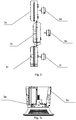
- Fig. 3a and Fig. 3b are part views of an air door structure of an air volume regulation device according to an embodiment of the invention
- Fig. 4 is a more detailed part view of an air door structure of an air volume regulation device according to an embodiment of the disclosure.
- the air door structure is provided in a housing 3c of the cabinet air conditioner, and is provided in a vicinity of a base 3d of the cabinet air conditioner.
- the air door structure comprises a baffle plate 3a, an air door motor 3b and a rack 3e.
- the baffle plate 3a is fixed at a tail end of the rack 3e, and a driving gear of the air door motor 3b is meshed with the rack 3e, thereby driving the rack 3e to move up and down.
- the baffle plate 3e moves to different positions along with the rack 3e, thereby opening or closing the lower air outlet.
- the baffle plate 3a and the lower air outlet are consistent in shape, so that airflows between the main air passage and the lower air outlet may be better cut off in a closed state.
- a sealing ring mounting part is provided on the baffle plate 3e. The sealing ring mounting part is configured to mount a sealing ring to implement sealing in the closed state, thereby avoiding air leakage.
- an additional guide structure is provided on the housing 3c, for example, a grooved structure.
- An edge of the baffle plate 3a is matched with the grooved structure, and slides along the grooved structure.
- the guide structure may also be provided to be another structure with a guide function, such as a guide block.
- Adopting the air door structure may implement multiple air outlet modes, thereby improving the comfort. For example, in a cooling mode, before an indoor temperature gets nearly constant, for preventing a condition that a temperature close to the ground is excessively low and makes people feel freezing, it is necessary to close an air door 3a at the lower air outlet under driving of the air door motor 3b, then the lower air outlet is in a closed state, and air is only blown from the upper air outlet.
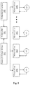
- Fig. 5 is a schematic diagram of a control system of an air volume regulation device according to an embodiment of the invention.
- the control system comprises a controller 101, an input provision device 102, a temperature sensor 103 and a plurality of motor drivers 203-20N.
- a plurality of motors M1-MN are also shown in Fig. 5 , and are configured to drive the plurality of fans shown in Fig. 1 respectively.
- the controller 101 comprises a master control chip, for example, a single-chip microcomputer and a Digital Signal Processor (DSP).
- the controller 101 receives a user instruction from the input provision device 102, receives an environmental sensing signal from the temperature sensor 103, and generates a control signal according to the received user instruction and environmental sensing signal.
- DSP Digital Signal Processor
- the controller 101 provides the control signal for the motor drivers 201-20N to control running of the fans.
- the input provision device 102 may be any piece of user input equipment, for example, a remote controller and a mobile phone, and is configured to provide the user instruction for the cabinet air conditioner, for example, starting, stopping, lower air blowing and air volume regulation of the air conditioner.
- the temperature sensor 103 is used to detect the environmental temperature, for example, a sensitive element comprising a thermistor.
- the motor drivers 201-20N are connected with the motors M1-MN respectively.
- the motor drivers provide power supply voltages for the motors, so that the motors may run.
- the motor drivers obtain feedback signals from the motors respectively, running parameters of the motors may be regulated.
- the feedback signals of the motors are, for example, rotating speed signals.
- Hall sensors are provided on rotors of the motors to obtain the rotating speed signals.
- the rotating speed signals may be no measured values but calculated values of a system algorithm.
- the air volumes of the fans depend on the rotating speeds of the fans, so that the air volumes of the fans may be estimated according to the rotating speeds.
- a corresponding relationship between an air volume and a rotating speed of a single fan may be obtained by tests for inverse deduction, and the rotating speed signals may be determined as signals feeding back the air volumes.
- the control system implements integrated air volume control of the plurality of fans.
- a form of combining the plurality of fans is adopted to maximally gather the air volumes.
- the control system may implement optimized real-time control to improve the comfort. For example, when the air conditioner is started for cooling or heating, the controller starts all the controlled fans to implement maximum air volume output to rapidly meet a temperature requirement set by the system. When the temperature reaches a value close to a set temperature, the controller may be switched into an energy-saving running state and properly turn off part of the fans for smooth transition.
- Whether to turn off part of the fans in a subsequent stage or not is judged according to a current running rotating speed of each of the plurality of fans to improve energy efficiency and achieve energy saving. For example, in an optimized control method, only one fan is left running, and the rotating speed of the fan is close to a rated value. Therefore, a low-efficiency state that the multiple fans are simultaneously started but all work at relatively low rotating speeds may be avoided.
- Fig. 6 is a flowchart of an air volume regulation method according to an embodiment of the invention.
- the air volume regulation method is described with a cooling process as an example.
- a control system shown in Fig. 5 is adopted to execute the following air volume regulation method.
- a controller 101 shown in Fig. 5 provides a control signal for a motor driver 201, then a motor M1 runs, and meanwhile, other motors stop working.
- different numbers of fans are started, and the rotating speed of each of the fans is controlled.
- Step S01 the air conditioning system is started for cooling.
- Step S02 a temperature sensor is adopted to detect an environmental temperature T environmental and judge whether a temperature difference between the environmental temperature T environmental and a preset temperature T preset is larger than a first threshold value ⁇ T1 or not, if it is not larger than the first threshold value ⁇ T1, Step S03 is subsequently executed, and if it is larger than the first threshold value ⁇ T1, Step S05 is subsequently executed.
- Step S03 whether the environmental temperature T environmental is lower than T preset or not is judged, if T environmental is lower than T preset , one fan is started in Step S04, and if T environmental is not lower than T preset , Step S05 is subsequently executed.
- Step S05 all the fans are started.
- Step S06 after the fans run for a period of time, the temperature sensor is adopted to detect the environmental temperature T environmental and judge whether the temperature difference between the environmental temperature T environmental and T preset is larger than a second threshold value ⁇ T2 or not, the second threshold value ⁇ T2 being smaller than the first threshold value ⁇ T1, which namely indicates that the temperature difference is reduced, if it is not larger than the second threshold value ⁇ T2, Step S02 is re-executed, and if it is larger than the second threshold value ⁇ T2, Step S07 is subsequently executed.
- Step S07 a current rotating speed of each of the fans is obtained according to feedback signals of the motors, whether a difference value between a rated rotating speed and current rotating speed of each of the fans is larger than a third threshold value ⁇ n or not is judged, if it is larger than the third threshold value ⁇ n, Step S08 is subsequently executed, and if it is not larger than the third threshold value ⁇ n, Step S02 is re-executed.
- Step S08 one fan is turned off, and the rotating speeds of the other running fans are increased, thereby ensuring that the running fans work at speeds in the vicinity of the rated rotating speed and all the running fans maintain the air volume of the system.
- first, second, third and the like may be adopted here to describe each element, part, region, layer and/or section, these elements, parts, regions, layers and/or sections should not be limited by these terms. These terms may only be adopt to distinguish one element, part, region, layer or section from another element, region, layer or section. Terms such as “first” and “second” and other numerical terms used here do not mean orders or sequences, unless explicitly specified in the context. Therefore, a first element, part, region, layer or section discussed below may be called as a second element, part, region, layer or section, without departing from the instruction of the exemplary embodiments. In addition, in the descriptions of the disclosure, “multiple” means two or more than two, unless otherwise noted.
- space-related terms such as “in”, “outside”, “under”, “below”, “lower part”, “above” and “upper part” are adopted here to describe a relationship between an element or characteristic and another element or characteristic shown in the drawings. It is understood that the space-related terms may be intended to include different orientations except orientations shown in the drawings during use or operation of equipment. For example, if the equipment in the drawings is overturned, an element described to be “below” or “under” another element or characteristic is to be positioned to be “above” the other element or characteristic. Therefore, the exemplary term “below” may include two directions above and below. The equipment may be oriented in another manner (rotating 90 degrees or at other orientations), and the space-related descriptors used here should be correspondingly explained.
Landscapes
- Engineering & Computer Science (AREA)
- Chemical & Material Sciences (AREA)
- Combustion & Propulsion (AREA)
- Mechanical Engineering (AREA)
- General Engineering & Computer Science (AREA)
- Signal Processing (AREA)
- Physics & Mathematics (AREA)
- Fuzzy Systems (AREA)
- Mathematical Physics (AREA)
- Fluid Mechanics (AREA)
- Air Conditioning Control Device (AREA)
Applications Claiming Priority (2)
| Application Number | Priority Date | Filing Date | Title |
|---|---|---|---|
| CN201510578301.7A CN105240930B (zh) | 2015-09-11 | 2015-09-11 | 风量调节装置的风量调节方法 |
| PCT/CN2016/098407 WO2017041726A1 (zh) | 2015-09-11 | 2016-09-08 | 风量调节装置及方法和空调柜机 |
Publications (3)
| Publication Number | Publication Date |
|---|---|
| EP3348917A1 true EP3348917A1 (de) | 2018-07-18 |
| EP3348917A4 EP3348917A4 (de) | 2019-04-24 |
| EP3348917B1 EP3348917B1 (de) | 2022-11-23 |
Family
ID=55038673
Family Applications (1)
| Application Number | Title | Priority Date | Filing Date |
|---|---|---|---|
| EP16843664.0A Active EP3348917B1 (de) | 2015-09-11 | 2016-09-08 | Luftvolumenregelungsverfahren |
Country Status (3)
| Country | Link |
|---|---|
| EP (1) | EP3348917B1 (de) |
| CN (1) | CN105240930B (de) |
| WO (1) | WO2017041726A1 (de) |
Families Citing this family (30)
| Publication number | Priority date | Publication date | Assignee | Title |
|---|---|---|---|---|
| CN105240930B (zh) * | 2015-09-11 | 2017-12-19 | 珠海格力电器股份有限公司 | 风量调节装置的风量调节方法 |
| CN106052040B (zh) * | 2016-07-04 | 2019-11-12 | 珠海格力电器股份有限公司 | 空调及其控制方法和装置 |
| CN107120783A (zh) * | 2017-03-22 | 2017-09-01 | 深圳市艾特网能技术有限公司 | 带有多风机空调系统的风机控制方法 |
| CN108731102A (zh) * | 2017-04-25 | 2018-11-02 | 青岛海尔空调器有限总公司 | 立式空调室内机 |
| CN107238173B (zh) * | 2017-05-19 | 2018-12-07 | 珠海格力电器股份有限公司 | 空调器及其控制方法、装置、存储介质和处理器 |
| CN107084513A (zh) * | 2017-06-21 | 2017-08-22 | 广东美的暖通设备有限公司 | 多风机空调的风机启动控制方法、装置及空调 |
| CN107155287A (zh) * | 2017-07-24 | 2017-09-12 | 郑州云海信息技术有限公司 | 一种服务器和服务器内风道的风量调节方法 |
| CN108151139A (zh) * | 2017-11-20 | 2018-06-12 | 珠海格力电器股份有限公司 | 柜式空调的控制方法、柜式空调、处理器、存储介质 |
| CN108488087B (zh) * | 2018-05-31 | 2024-07-02 | 王梓豫 | 一种节流式降温电风扇及其控制方法 |
| CN111197584A (zh) * | 2018-11-20 | 2020-05-26 | 珠海格力电器股份有限公司 | 一种离心风机、风道系统及空调 |
| CN109595691B (zh) * | 2018-12-20 | 2020-05-01 | 珠海格力电器股份有限公司 | 一种双贯流空调器的控制方法 |
| CN109539505B (zh) * | 2018-12-29 | 2021-04-20 | 青岛海尔空调器有限总公司 | 空调的控制方法、装置、存储介质及计算机设备 |
| CN110160150B (zh) * | 2019-06-25 | 2024-05-10 | 宁波奥克斯电气股份有限公司 | 一种风道壳体、上风道组件及空调器 |
| CN110131789B (zh) * | 2019-06-25 | 2024-07-16 | 宁波奥克斯电气股份有限公司 | 出风组件及空调器 |
| CN110260488A (zh) * | 2019-06-25 | 2019-09-20 | 宁波奥克斯电气股份有限公司 | 电机功率控制方法、装置及空调器 |
| CN110486802B (zh) * | 2019-08-19 | 2021-02-19 | 南京晶华智能科技有限公司 | 空调器、其送风调节系统和方法 |
| CN111750425B (zh) * | 2020-05-18 | 2022-05-31 | 海信(山东)空调有限公司 | 一种室内空调器 |
| CN111902023B (zh) * | 2020-07-28 | 2023-06-30 | 深圳市科信通信技术股份有限公司 | 一种机柜风量控制系统及控制方法 |
| CN114135971B (zh) * | 2020-09-04 | 2023-04-07 | 宁波奥克斯电气股份有限公司 | 一种空调器的出风控制方法、装置、控制器及存储介质 |
| CN112984725B (zh) * | 2021-02-07 | 2022-04-19 | 青岛海尔空调器有限总公司 | 一种水洗下出风空调的控制方法和水洗下出风空调 |
| CN112984729B (zh) * | 2021-02-07 | 2022-04-19 | 青岛海尔空调器有限总公司 | 一种下出风空调的控制方法和下出风空调 |
| CN112944627B (zh) * | 2021-03-02 | 2022-04-19 | 青岛海尔空调器有限总公司 | 一种下出风空调的控制方法和下出风空调 |
| CN113048563B (zh) * | 2021-04-25 | 2022-07-12 | 宁波奥克斯电气股份有限公司 | 空调柜机控制方法、装置及空调柜机 |
| CN113323903B (zh) * | 2021-06-18 | 2023-08-08 | 广东湾区智能终端工业设计研究院有限公司 | 风扇热启动方法及装置 |
| CN115234279B (zh) * | 2022-07-29 | 2025-05-27 | 济南嘉宏科技有限责任公司 | 一种矿井下智能气动风窗精准调节装置和方法 |
| CN115183439A (zh) * | 2022-08-05 | 2022-10-14 | 宁波奥克斯电气股份有限公司 | 一种多风口空调控制方法、装置及空调器 |
| CN115666107A (zh) * | 2022-11-16 | 2023-01-31 | 联宝(合肥)电子科技有限公司 | 一种散热装置以及电子设备 |
| CN119123533B (zh) * | 2023-06-12 | 2025-12-30 | 青岛海尔空调电子有限公司 | 用于控制空调器电加热装置的方法及装置、空调器 |
| CN119436264A (zh) * | 2023-08-07 | 2025-02-14 | 青岛海尔空调电子有限公司 | 柜式室内机及空调 |
| KR20250103074A (ko) * | 2023-12-28 | 2025-07-07 | 삼성전자주식회사 | 공기 조화기 및 그 제어 방법 |
Family Cites Families (20)
| Publication number | Priority date | Publication date | Assignee | Title |
|---|---|---|---|---|
| EP0154461A3 (de) * | 1984-02-25 | 1987-07-15 | Nishida Tekko Corporation | Gerät zur Umwälzung von Raumluft |
| JPS63161343A (ja) * | 1986-12-24 | 1988-07-05 | Matsushita Electric Ind Co Ltd | 空気調和機の風量制御装置 |
| CN1010707B (zh) * | 1987-07-02 | 1990-12-05 | 三菱电机株式会社 | 分离型空气调节器 |
| US5810658A (en) * | 1995-11-30 | 1998-09-22 | Samsung Electronics Co., Ltd. | Interlocking device for closing or opening the suction and exhaust ports in air conditioners |
| JP4766889B2 (ja) * | 2005-03-16 | 2011-09-07 | 三菱電機株式会社 | 空気調和機 |
| CN201166438Y (zh) * | 2007-11-23 | 2008-12-17 | 艾斯比特制热电器(上海)有限公司 | 扇形产品面板 |
| CN101650064A (zh) * | 2008-08-14 | 2010-02-17 | 海尔集团公司 | 低温制冷空调及其风速控制方法 |
| CN102466299A (zh) * | 2010-11-16 | 2012-05-23 | 珠海格力电器股份有限公司 | 风管机系统及其控制系统 |
| US9551498B2 (en) * | 2012-06-28 | 2017-01-24 | Samsung Electronics Co., Ltd. | Indoor unit of air conditioner and method of controlling the air conditioner |
| CN202792281U (zh) * | 2012-07-30 | 2013-03-13 | 广东美的暖通设备有限公司 | 冷凝器及具有该冷凝器的空调室外机 |
| CN103776094A (zh) * | 2012-10-23 | 2014-05-07 | 珠海格力电器股份有限公司 | 空调器室内机及具有其的空调器 |
| CN202973363U (zh) * | 2012-12-13 | 2013-06-05 | 珠海格力电器股份有限公司 | 空调器 |
| CN103307713B (zh) * | 2013-05-28 | 2016-06-15 | 广东美的制冷设备有限公司 | 多风档转速控制方法及装置 |
| KR102136647B1 (ko) * | 2013-06-10 | 2020-07-22 | 삼성전자주식회사 | 공기 조화기 및 그 제어 방법 |
| CN103512155B (zh) * | 2013-09-30 | 2016-06-08 | 美的集团股份有限公司 | 一种空调控制方法及控制系统 |
| CN104515287A (zh) * | 2013-09-30 | 2015-04-15 | 海尔集团公司 | 空调及其控制方法 |
| CN204006499U (zh) * | 2014-04-03 | 2014-12-10 | 杭州先途电子有限公司 | 空调控制器及其安全控制电路 |
| CN104748234B (zh) * | 2015-03-30 | 2018-04-27 | 广东美的制冷设备有限公司 | 空调器 |
| CN104776575B (zh) * | 2015-03-31 | 2018-09-11 | 珠海格力电器股份有限公司 | 空调器室内机 |
| CN105240930B (zh) * | 2015-09-11 | 2017-12-19 | 珠海格力电器股份有限公司 | 风量调节装置的风量调节方法 |
-
2015
- 2015-09-11 CN CN201510578301.7A patent/CN105240930B/zh active Active
-
2016
- 2016-09-08 WO PCT/CN2016/098407 patent/WO2017041726A1/zh not_active Ceased
- 2016-09-08 EP EP16843664.0A patent/EP3348917B1/de active Active
Also Published As
| Publication number | Publication date |
|---|---|
| WO2017041726A1 (zh) | 2017-03-16 |
| EP3348917A4 (de) | 2019-04-24 |
| CN105240930A (zh) | 2016-01-13 |
| CN105240930B (zh) | 2017-12-19 |
| EP3348917B1 (de) | 2022-11-23 |
Similar Documents
| Publication | Publication Date | Title |
|---|---|---|
| EP3348917B1 (de) | Luftvolumenregelungsverfahren | |
| CN106247565B (zh) | 空调的送风方法、装置和系统 | |
| US10406888B2 (en) | Electric vehicle thermal management system | |
| CN103822327B (zh) | 一种变频空调器电加热控制方法 | |
| CN105066334B (zh) | 空调器及其控制方法、控制装置 | |
| CN104110780B (zh) | 空调器及其电辅热的控制方法和系统 | |
| CN110260487A (zh) | 出风控制方法、装置及上下出风柜机 | |
| CN107763933B (zh) | 冰箱的制冷控制方法与冰箱 | |
| KR20100064609A (ko) | 차량용 공기조화기의 공기유입방법 및 그 시스템 | |
| CN106813360B (zh) | 多联机系统及其室内机的防冷风控制方法和装置 | |
| US20170326718A1 (en) | Hand-Held Power Tool, Fanless Storage Battery | |
| CN110100136A (zh) | 空调以及电机控制装置 | |
| KR20250088595A (ko) | 열 관리 제어 방법, 열 관리 제어 장치 및 차량 | |
| CN113203171A (zh) | 一种空调控制方法、装置、空调及计算机可读存储介质 | |
| EP3098547A1 (de) | Kühlschrank vom typ einer einfachen invertersteuerung, invertersteuerungseinheit für kühlschrank und inverterverdichter damit | |
| CN112880148A (zh) | 用于空调的控制方法、装置、电子设备及存储介质 | |
| CN109405164A (zh) | 设备及其风管机控制方法和装置 | |
| CN114963482A (zh) | 空调器的控制方法、空调器以及存储介质 | |
| CN113531825A (zh) | 用于控制热泵热水器空调的方法及装置、热泵热水器空调 | |
| JP2012239344A (ja) | 電動車両の暖機装置 | |
| CN202586717U (zh) | 变频器散热冷却系统 | |
| JP5455338B2 (ja) | 冷却塔及び熱源機システム | |
| CN109489216B (zh) | 一种舒适性风管送风式空调的控制方法 | |
| CN107726566A (zh) | 多联式新风系统及其控制方法 | |
| CN112361562A (zh) | 一种电控箱降温装置、降温控制方法及空调机组 |
Legal Events
| Date | Code | Title | Description |
|---|---|---|---|
| STAA | Information on the status of an ep patent application or granted ep patent |
Free format text: STATUS: THE INTERNATIONAL PUBLICATION HAS BEEN MADE |
|
| PUAI | Public reference made under article 153(3) epc to a published international application that has entered the european phase |
Free format text: ORIGINAL CODE: 0009012 |
|
| STAA | Information on the status of an ep patent application or granted ep patent |
Free format text: STATUS: REQUEST FOR EXAMINATION WAS MADE |
|
| 17P | Request for examination filed |
Effective date: 20180410 |
|
| AK | Designated contracting states |
Kind code of ref document: A1 Designated state(s): AL AT BE BG CH CY CZ DE DK EE ES FI FR GB GR HR HU IE IS IT LI LT LU LV MC MK MT NL NO PL PT RO RS SE SI SK SM TR |
|
| AX | Request for extension of the european patent |
Extension state: BA ME |
|
| DAV | Request for validation of the european patent (deleted) | ||
| DAX | Request for extension of the european patent (deleted) | ||
| A4 | Supplementary search report drawn up and despatched |
Effective date: 20190327 |
|
| RIC1 | Information provided on ipc code assigned before grant |
Ipc: F24F 11/74 20180101ALI20190321BHEP Ipc: F24F 1/0033 20190101ALI20190321BHEP Ipc: F24F 11/00 20180101ALI20190321BHEP Ipc: F24F 1/00 20190101AFI20190321BHEP Ipc: F24F 110/10 20180101ALI20190321BHEP Ipc: F24F 11/65 20180101ALI20190321BHEP Ipc: F24F 1/0043 20190101ALI20190321BHEP Ipc: F24F 11/64 20180101ALI20190321BHEP Ipc: F24F 1/0014 20190101ALI20190321BHEP Ipc: F24F 11/77 20180101ALI20190321BHEP |
|
| GRAP | Despatch of communication of intention to grant a patent |
Free format text: ORIGINAL CODE: EPIDOSNIGR1 |
|
| STAA | Information on the status of an ep patent application or granted ep patent |
Free format text: STATUS: GRANT OF PATENT IS INTENDED |
|
| INTG | Intention to grant announced |
Effective date: 20220630 |
|
| GRAS | Grant fee paid |
Free format text: ORIGINAL CODE: EPIDOSNIGR3 |
|
| GRAA | (expected) grant |
Free format text: ORIGINAL CODE: 0009210 |
|
| STAA | Information on the status of an ep patent application or granted ep patent |
Free format text: STATUS: THE PATENT HAS BEEN GRANTED |
|
| AK | Designated contracting states |
Kind code of ref document: B1 Designated state(s): AL AT BE BG CH CY CZ DE DK EE ES FI FR GB GR HR HU IE IS IT LI LT LU LV MC MK MT NL NO PL PT RO RS SE SI SK SM TR |
|
| REG | Reference to a national code |
Ref country code: GB Ref legal event code: FG4D |
|
| REG | Reference to a national code |
Ref country code: CH Ref legal event code: EP |
|
| REG | Reference to a national code |
Ref country code: AT Ref legal event code: REF Ref document number: 1533339 Country of ref document: AT Kind code of ref document: T Effective date: 20221215 Ref country code: DE Ref legal event code: R096 Ref document number: 602016076521 Country of ref document: DE |
|
| REG | Reference to a national code |
Ref country code: IE Ref legal event code: FG4D |
|
| REG | Reference to a national code |
Ref country code: LT Ref legal event code: MG9D |
|
| REG | Reference to a national code |
Ref country code: NL Ref legal event code: MP Effective date: 20221123 |
|
| REG | Reference to a national code |
Ref country code: AT Ref legal event code: MK05 Ref document number: 1533339 Country of ref document: AT Kind code of ref document: T Effective date: 20221123 |
|
| PG25 | Lapsed in a contracting state [announced via postgrant information from national office to epo] |
Ref country code: SE Free format text: LAPSE BECAUSE OF FAILURE TO SUBMIT A TRANSLATION OF THE DESCRIPTION OR TO PAY THE FEE WITHIN THE PRESCRIBED TIME-LIMIT Effective date: 20221123 Ref country code: PT Free format text: LAPSE BECAUSE OF FAILURE TO SUBMIT A TRANSLATION OF THE DESCRIPTION OR TO PAY THE FEE WITHIN THE PRESCRIBED TIME-LIMIT Effective date: 20230323 Ref country code: NO Free format text: LAPSE BECAUSE OF FAILURE TO SUBMIT A TRANSLATION OF THE DESCRIPTION OR TO PAY THE FEE WITHIN THE PRESCRIBED TIME-LIMIT Effective date: 20230223 Ref country code: LT Free format text: LAPSE BECAUSE OF FAILURE TO SUBMIT A TRANSLATION OF THE DESCRIPTION OR TO PAY THE FEE WITHIN THE PRESCRIBED TIME-LIMIT Effective date: 20221123 Ref country code: FI Free format text: LAPSE BECAUSE OF FAILURE TO SUBMIT A TRANSLATION OF THE DESCRIPTION OR TO PAY THE FEE WITHIN THE PRESCRIBED TIME-LIMIT Effective date: 20221123 Ref country code: ES Free format text: LAPSE BECAUSE OF FAILURE TO SUBMIT A TRANSLATION OF THE DESCRIPTION OR TO PAY THE FEE WITHIN THE PRESCRIBED TIME-LIMIT Effective date: 20221123 Ref country code: AT Free format text: LAPSE BECAUSE OF FAILURE TO SUBMIT A TRANSLATION OF THE DESCRIPTION OR TO PAY THE FEE WITHIN THE PRESCRIBED TIME-LIMIT Effective date: 20221123 |
|
| PG25 | Lapsed in a contracting state [announced via postgrant information from national office to epo] |
Ref country code: RS Free format text: LAPSE BECAUSE OF FAILURE TO SUBMIT A TRANSLATION OF THE DESCRIPTION OR TO PAY THE FEE WITHIN THE PRESCRIBED TIME-LIMIT Effective date: 20221123 Ref country code: PL Free format text: LAPSE BECAUSE OF FAILURE TO SUBMIT A TRANSLATION OF THE DESCRIPTION OR TO PAY THE FEE WITHIN THE PRESCRIBED TIME-LIMIT Effective date: 20221123 Ref country code: LV Free format text: LAPSE BECAUSE OF FAILURE TO SUBMIT A TRANSLATION OF THE DESCRIPTION OR TO PAY THE FEE WITHIN THE PRESCRIBED TIME-LIMIT Effective date: 20221123 Ref country code: IS Free format text: LAPSE BECAUSE OF FAILURE TO SUBMIT A TRANSLATION OF THE DESCRIPTION OR TO PAY THE FEE WITHIN THE PRESCRIBED TIME-LIMIT Effective date: 20230323 Ref country code: HR Free format text: LAPSE BECAUSE OF FAILURE TO SUBMIT A TRANSLATION OF THE DESCRIPTION OR TO PAY THE FEE WITHIN THE PRESCRIBED TIME-LIMIT Effective date: 20221123 Ref country code: GR Free format text: LAPSE BECAUSE OF FAILURE TO SUBMIT A TRANSLATION OF THE DESCRIPTION OR TO PAY THE FEE WITHIN THE PRESCRIBED TIME-LIMIT Effective date: 20230224 |
|
| PG25 | Lapsed in a contracting state [announced via postgrant information from national office to epo] |
Ref country code: NL Free format text: LAPSE BECAUSE OF FAILURE TO SUBMIT A TRANSLATION OF THE DESCRIPTION OR TO PAY THE FEE WITHIN THE PRESCRIBED TIME-LIMIT Effective date: 20221123 |
|
| P01 | Opt-out of the competence of the unified patent court (upc) registered |
Effective date: 20230530 |
|
| PG25 | Lapsed in a contracting state [announced via postgrant information from national office to epo] |
Ref country code: SM Free format text: LAPSE BECAUSE OF FAILURE TO SUBMIT A TRANSLATION OF THE DESCRIPTION OR TO PAY THE FEE WITHIN THE PRESCRIBED TIME-LIMIT Effective date: 20221123 Ref country code: RO Free format text: LAPSE BECAUSE OF FAILURE TO SUBMIT A TRANSLATION OF THE DESCRIPTION OR TO PAY THE FEE WITHIN THE PRESCRIBED TIME-LIMIT Effective date: 20221123 Ref country code: EE Free format text: LAPSE BECAUSE OF FAILURE TO SUBMIT A TRANSLATION OF THE DESCRIPTION OR TO PAY THE FEE WITHIN THE PRESCRIBED TIME-LIMIT Effective date: 20221123 Ref country code: DK Free format text: LAPSE BECAUSE OF FAILURE TO SUBMIT A TRANSLATION OF THE DESCRIPTION OR TO PAY THE FEE WITHIN THE PRESCRIBED TIME-LIMIT Effective date: 20221123 Ref country code: CZ Free format text: LAPSE BECAUSE OF FAILURE TO SUBMIT A TRANSLATION OF THE DESCRIPTION OR TO PAY THE FEE WITHIN THE PRESCRIBED TIME-LIMIT Effective date: 20221123 |
|
| REG | Reference to a national code |
Ref country code: DE Ref legal event code: R097 Ref document number: 602016076521 Country of ref document: DE |
|
| PG25 | Lapsed in a contracting state [announced via postgrant information from national office to epo] |
Ref country code: SK Free format text: LAPSE BECAUSE OF FAILURE TO SUBMIT A TRANSLATION OF THE DESCRIPTION OR TO PAY THE FEE WITHIN THE PRESCRIBED TIME-LIMIT Effective date: 20221123 Ref country code: AL Free format text: LAPSE BECAUSE OF FAILURE TO SUBMIT A TRANSLATION OF THE DESCRIPTION OR TO PAY THE FEE WITHIN THE PRESCRIBED TIME-LIMIT Effective date: 20221123 |
|
| PLBE | No opposition filed within time limit |
Free format text: ORIGINAL CODE: 0009261 |
|
| STAA | Information on the status of an ep patent application or granted ep patent |
Free format text: STATUS: NO OPPOSITION FILED WITHIN TIME LIMIT |
|
| 26N | No opposition filed |
Effective date: 20230824 |
|
| PG25 | Lapsed in a contracting state [announced via postgrant information from national office to epo] |
Ref country code: SI Free format text: LAPSE BECAUSE OF FAILURE TO SUBMIT A TRANSLATION OF THE DESCRIPTION OR TO PAY THE FEE WITHIN THE PRESCRIBED TIME-LIMIT Effective date: 20221123 |
|
| REG | Reference to a national code |
Ref country code: CH Ref legal event code: PL |
|
| PG25 | Lapsed in a contracting state [announced via postgrant information from national office to epo] |
Ref country code: LU Free format text: LAPSE BECAUSE OF NON-PAYMENT OF DUE FEES Effective date: 20230908 |
|
| REG | Reference to a national code |
Ref country code: BE Ref legal event code: MM Effective date: 20230930 |
|
| GBPC | Gb: european patent ceased through non-payment of renewal fee |
Effective date: 20230908 |
|
| PG25 | Lapsed in a contracting state [announced via postgrant information from national office to epo] |
Ref country code: LU Free format text: LAPSE BECAUSE OF NON-PAYMENT OF DUE FEES Effective date: 20230908 Ref country code: IT Free format text: LAPSE BECAUSE OF FAILURE TO SUBMIT A TRANSLATION OF THE DESCRIPTION OR TO PAY THE FEE WITHIN THE PRESCRIBED TIME-LIMIT Effective date: 20221123 Ref country code: MC Free format text: LAPSE BECAUSE OF FAILURE TO SUBMIT A TRANSLATION OF THE DESCRIPTION OR TO PAY THE FEE WITHIN THE PRESCRIBED TIME-LIMIT Effective date: 20221123 |
|
| REG | Reference to a national code |
Ref country code: IE Ref legal event code: MM4A |
|
| PG25 | Lapsed in a contracting state [announced via postgrant information from national office to epo] |
Ref country code: IE Free format text: LAPSE BECAUSE OF NON-PAYMENT OF DUE FEES Effective date: 20230908 |
|
| PG25 | Lapsed in a contracting state [announced via postgrant information from national office to epo] |
Ref country code: GB Free format text: LAPSE BECAUSE OF NON-PAYMENT OF DUE FEES Effective date: 20230908 |
|
| PG25 | Lapsed in a contracting state [announced via postgrant information from national office to epo] |
Ref country code: CH Free format text: LAPSE BECAUSE OF NON-PAYMENT OF DUE FEES Effective date: 20230930 |
|
| PG25 | Lapsed in a contracting state [announced via postgrant information from national office to epo] |
Ref country code: IE Free format text: LAPSE BECAUSE OF NON-PAYMENT OF DUE FEES Effective date: 20230908 Ref country code: GB Free format text: LAPSE BECAUSE OF NON-PAYMENT OF DUE FEES Effective date: 20230908 Ref country code: FR Free format text: LAPSE BECAUSE OF NON-PAYMENT OF DUE FEES Effective date: 20230930 Ref country code: CH Free format text: LAPSE BECAUSE OF NON-PAYMENT OF DUE FEES Effective date: 20230930 |
|
| PG25 | Lapsed in a contracting state [announced via postgrant information from national office to epo] |
Ref country code: BE Free format text: LAPSE BECAUSE OF NON-PAYMENT OF DUE FEES Effective date: 20230930 |
|
| PG25 | Lapsed in a contracting state [announced via postgrant information from national office to epo] |
Ref country code: BG Free format text: LAPSE BECAUSE OF FAILURE TO SUBMIT A TRANSLATION OF THE DESCRIPTION OR TO PAY THE FEE WITHIN THE PRESCRIBED TIME-LIMIT Effective date: 20221123 |
|
| PG25 | Lapsed in a contracting state [announced via postgrant information from national office to epo] |
Ref country code: BG Free format text: LAPSE BECAUSE OF FAILURE TO SUBMIT A TRANSLATION OF THE DESCRIPTION OR TO PAY THE FEE WITHIN THE PRESCRIBED TIME-LIMIT Effective date: 20221123 |
|
| PG25 | Lapsed in a contracting state [announced via postgrant information from national office to epo] |
Ref country code: CY Free format text: LAPSE BECAUSE OF FAILURE TO SUBMIT A TRANSLATION OF THE DESCRIPTION OR TO PAY THE FEE WITHIN THE PRESCRIBED TIME-LIMIT; INVALID AB INITIO Effective date: 20160908 |
|
| PG25 | Lapsed in a contracting state [announced via postgrant information from national office to epo] |
Ref country code: HU Free format text: LAPSE BECAUSE OF FAILURE TO SUBMIT A TRANSLATION OF THE DESCRIPTION OR TO PAY THE FEE WITHIN THE PRESCRIBED TIME-LIMIT; INVALID AB INITIO Effective date: 20160908 |
|
| PGFP | Annual fee paid to national office [announced via postgrant information from national office to epo] |
Ref country code: DE Payment date: 20250919 Year of fee payment: 10 |
|
| PG25 | Lapsed in a contracting state [announced via postgrant information from national office to epo] |
Ref country code: TR Free format text: LAPSE BECAUSE OF FAILURE TO SUBMIT A TRANSLATION OF THE DESCRIPTION OR TO PAY THE FEE WITHIN THE PRESCRIBED TIME-LIMIT Effective date: 20221123 |