EP3348963A1 - Dispositif de navigation et système de sondage - Google Patents
Dispositif de navigation et système de sondage Download PDFInfo
- Publication number
- EP3348963A1 EP3348963A1 EP15903572.4A EP15903572A EP3348963A1 EP 3348963 A1 EP3348963 A1 EP 3348963A1 EP 15903572 A EP15903572 A EP 15903572A EP 3348963 A1 EP3348963 A1 EP 3348963A1
- Authority
- EP
- European Patent Office
- Prior art keywords
- data
- image
- coordinates
- distance
- attitude
- Prior art date
- Legal status (The legal status is an assumption and is not a legal conclusion. Google has not performed a legal analysis and makes no representation as to the accuracy of the status listed.)
- Granted
Links
Images






Classifications
-
- G—PHYSICS
- G01—MEASURING; TESTING
- G01C—MEASURING DISTANCES, LEVELS OR BEARINGS; SURVEYING; NAVIGATION; GYROSCOPIC INSTRUMENTS; PHOTOGRAMMETRY OR VIDEOGRAMMETRY
- G01C11/00—Photogrammetry or videogrammetry, e.g. stereogrammetry; Photographic surveying
- G01C11/04—Interpretation of pictures
- G01C11/06—Interpretation of pictures by comparison of two or more pictures of the same area
-
- B—PERFORMING OPERATIONS; TRANSPORTING
- B64—AIRCRAFT; AVIATION; COSMONAUTICS
- B64D—EQUIPMENT FOR FITTING IN OR TO AIRCRAFT; FLIGHT SUITS; PARACHUTES; ARRANGEMENT OR MOUNTING OF POWER PLANTS OR PROPULSION TRANSMISSIONS IN AIRCRAFT
- B64D47/00—Equipment not otherwise provided for
- B64D47/08—Arrangements of cameras
-
- G—PHYSICS
- G01—MEASURING; TESTING
- G01B—MEASURING LENGTH, THICKNESS OR SIMILAR LINEAR DIMENSIONS; MEASURING ANGLES; MEASURING AREAS; MEASURING IRREGULARITIES OF SURFACES OR CONTOURS
- G01B11/00—Measuring arrangements characterised by the use of optical techniques
- G01B11/002—Measuring arrangements characterised by the use of optical techniques for measuring two or more coordinates
-
- G—PHYSICS
- G01—MEASURING; TESTING
- G01C—MEASURING DISTANCES, LEVELS OR BEARINGS; SURVEYING; NAVIGATION; GYROSCOPIC INSTRUMENTS; PHOTOGRAMMETRY OR VIDEOGRAMMETRY
- G01C1/00—Measuring angles
- G01C1/02—Theodolites
- G01C1/04—Theodolites combined with cameras
-
- G—PHYSICS
- G01—MEASURING; TESTING
- G01S—RADIO DIRECTION-FINDING; RADIO NAVIGATION; DETERMINING DISTANCE OR VELOCITY BY USE OF RADIO WAVES; LOCATING OR PRESENCE-DETECTING BY USE OF THE REFLECTION OR RERADIATION OF RADIO WAVES; ANALOGOUS ARRANGEMENTS USING OTHER WAVES
- G01S17/00—Systems using the reflection or reradiation of electromagnetic waves other than radio waves, e.g. lidar systems
- G01S17/02—Systems using the reflection of electromagnetic waves other than radio waves
- G01S17/06—Systems determining position data of a target
- G01S17/42—Simultaneous measurement of distance and other co-ordinates
-
- G—PHYSICS
- G01—MEASURING; TESTING
- G01S—RADIO DIRECTION-FINDING; RADIO NAVIGATION; DETERMINING DISTANCE OR VELOCITY BY USE OF RADIO WAVES; LOCATING OR PRESENCE-DETECTING BY USE OF THE REFLECTION OR RERADIATION OF RADIO WAVES; ANALOGOUS ARRANGEMENTS USING OTHER WAVES
- G01S17/00—Systems using the reflection or reradiation of electromagnetic waves other than radio waves, e.g. lidar systems
- G01S17/86—Combinations of lidar systems with systems other than lidar, radar or sonar, e.g. with direction finders
-
- G—PHYSICS
- G06—COMPUTING OR CALCULATING; COUNTING
- G06T—IMAGE DATA PROCESSING OR GENERATION, IN GENERAL
- G06T7/00—Image analysis
- G06T7/50—Depth or shape recovery
- G06T7/55—Depth or shape recovery from multiple images
- G06T7/593—Depth or shape recovery from multiple images from stereo images
-
- G—PHYSICS
- G06—COMPUTING OR CALCULATING; COUNTING
- G06T—IMAGE DATA PROCESSING OR GENERATION, IN GENERAL
- G06T7/00—Image analysis
- G06T7/70—Determining position or orientation of objects or cameras
-
- H—ELECTRICITY
- H04—ELECTRIC COMMUNICATION TECHNIQUE
- H04N—PICTORIAL COMMUNICATION, e.g. TELEVISION
- H04N7/00—Television systems
- H04N7/18—Closed-circuit television [CCTV] systems, i.e. systems in which the video signal is not broadcast
- H04N7/183—Closed-circuit television [CCTV] systems, i.e. systems in which the video signal is not broadcast for receiving images from a single remote source
- H04N7/185—Closed-circuit television [CCTV] systems, i.e. systems in which the video signal is not broadcast for receiving images from a single remote source from a mobile camera, e.g. for remote control
-
- G—PHYSICS
- G05—CONTROLLING; REGULATING
- G05D—SYSTEMS FOR CONTROLLING OR REGULATING NON-ELECTRIC VARIABLES
- G05D1/00—Control of position, course, altitude or attitude of land, water, air or space vehicles, e.g. using automatic pilots
- G05D1/08—Control of attitude, i.e. control of roll, pitch, or yaw
-
- G—PHYSICS
- G06—COMPUTING OR CALCULATING; COUNTING
- G06T—IMAGE DATA PROCESSING OR GENERATION, IN GENERAL
- G06T2207/00—Indexing scheme for image analysis or image enhancement
- G06T2207/10—Image acquisition modality
- G06T2207/10032—Satellite or aerial image; Remote sensing
-
- G—PHYSICS
- G06—COMPUTING OR CALCULATING; COUNTING
- G06T—IMAGE DATA PROCESSING OR GENERATION, IN GENERAL
- G06T2207/00—Indexing scheme for image analysis or image enhancement
- G06T2207/30—Subject of image; Context of image processing
- G06T2207/30244—Camera pose
Definitions
- the present invention relates to a navigation system that estimates the attitude of a moving body in which a camera for surveys and a laser distance measuring device are mounted, and a survey system provided with this navigation system.
- Patent Literature 1 discloses a survey system that performs photographic surveying and airborne laser scanning by using a camera and a laser emitting and receiving device which are mounted in a flying body.
- the camera that shoots a survey target from the flying body is supported by an attitude stabilizing device called a stabilizer, and the shooting direction can be kept aligned with a vertically downward direction regardless of the attitude of the flying body in flight.
- the laser emitting and receiving device projects laser light to a survey target from the flying body at a predetermined period, and receives light reflected from this survey target.
- a control device in this survey system performs the airborne laser scanning by using information about the reflected light from the survey target which is received by the laser emitting and receiving device.
- the laser emitting and receiving device corresponds to a laser distance measuring device according to the present invention.
- both three-dimensional coordinate data about the flying body (the horizontal position and the altitude of the flying body) and information showing the attitude of the flying body in flight are needed in addition to the above-mentioned information.
- the three-dimensional coordinate data about the flying body is detected by a GNSS (Global Navigation Satellite System) device mounted in the flying body. More specifically, the GNSS device receives GNSS information from a GNSS satellite at a predetermined period, and analyzes this GNSS information to acquire the three-dimensional coordinate data about the flying body.
- GNSS Global Navigation Satellite System
- the length of the period at which the laser light is projected to a survey target by the laser emitting and receiving device is shorter than the length of the period at which GNSS information is received by the GNSS device. Therefore, even if reflected light from a survey target is received by the laser emitting and receiving device, the control device cannot acquire the three-dimensional coordinate data about the flying body at a certain period not matching the period at which GNSS information is received.
- three-dimensional coordinate data about a flying body are acquired at a certain period other than the period at which GNSS information is received, by using information about acceleration along three axes and angular acceleration along three axes which are measured by an IMU (Inertial Measurement Unit) mounted in the flying body.
- IMU Inertial Measurement Unit
- the IMU is very expensive and is relatively heavy, a limitation is imposed on the types of flying bodies into which this IMU can be incorporated.
- this survey system acquires three-dimensional coordinate data about a flying body at a certain period not matching the period at which GNSS information is received, by using both information about acceleration along three axes from the accelerometer and information about angular acceleration along three axes from the angular accelerometer.
- information showing the attitude of the flying body is angles in a rolling direction, a pitching direction and a yawing direction of the flying body (referred to as a roll angle, a pitch angle and a yaw angle from here on), and values acquired by bundle calculation for corresponding points of images which are shot from two or more different positions by a camera are used.
- the control device calculates an attitude of the flying body at each scan period of laser light (this period does not match the period at which the GNSS information is received) in accordance with the attitude of the flying body acquired by the bundle calculation and by using both the acceleration from the accelerometer and the angular acceleration from the angular accelerometer.
- Patent Literature 1 Japanese Unexamined Patent Application Publication No. 2014-145762
- Patent Literature 1 estimates the attitude of the flying body by the bundle calculation using the image data about images captured from different positions by a camera, and uses only the image data for the estimation of the attitude. Therefore, the estimation accuracy of the attitude has a limit.
- the above-mentioned survey system is based on the premise that information of images to be used for the estimation of the attitude of the flying body is taken with the camera pointing vertically downward with respect to the flying body, regardless of the attitude of the flying body.
- the present invention is made in order to solve the above-mentioned problems, and it is therefore an object of the present invention to provide a navigation system and a survey system capable of estimating the attitude of a moving body with a high degree of accuracy by using a configuration not having any IMU and any stabilizer.
- a navigation system including: a data acquiring unit for acquiring distance data showing a distance from a projection reference point of laser light to a distance measurement point, the distance being measured by a laser distance measuring device mounted in a moving body, angle data showing a projection angle of the laser light, coordinate data showing three-dimensional coordinates of the projection reference point of the laser light, the three-dimensional coordinates being measured by a coordinate measuring device mounted in the moving body, and image data containing a distance measurement point on an object taken by an image shooting device mounted in the moving body; a coordinate calculating unit for calculating coordinates of the distance measurement point on an image shown by the image data on a basis of the distance data, the angle data and the coordinate data that are acquired by the data acquiring unit, and a parameter showing an attitude of the moving body; an image matching unit for performing image matching on a pair of pieces of image data taken by the image shooting device at different shooting positions, and searching an image shown by one image data of the pair for a point corresponding to coordinates of a distance measurement
- the navigation system pays attention to the fact that the coordinates of corresponding points between images shot at different shooting positions deviate from each other dependently on the attitude of the moving body, and corrects the value of the parameter showing the attitude of the moving body in such a way that the difference between these coordinates becomes small, to estimate the attitude of the moving body, the navigation system can estimate the attitude of the moving body even if the navigation system does not use an IMU and a stabilizer.
- the navigation system estimates the attitude of the moving body by using, in addition to image data about an image containing a shot distance measurement point, the distance from the projection reference point of laser light to the distance measurement point, the projection angle of the laser light and the three-dimensional coordinates of the projection reference point of the laser light, the navigation system can estimate the attitude of the moving body with a high degree of accuracy.
- Fig. 1 is a block diagram showing the configuration of a survey system 1 according to Embodiment 1 of the present invention.
- the survey system 1 surveys geographical features from an airplane 2, and includes a left camera 20a, a right camera 20b, a laser distance measuring device 21, a GNSS device 22 and a memory card 23 which are mounted in the airplane 2, and a navigation system 3.
- the navigation system 3 estimates the attitude of the airplane 2 in flight, and, as shown in Fig. 1 , is disposed separately from the airplane 2. Alternatively, the navigation system 3 may be mounted in the airplane 2.
- attitude of the airplane 2 is specified by the following three parameters: a roll angle ⁇ , a pitch angle ⁇ and a yaw angle ⁇ which are attitude angles in a rolling direction, in a pitching direction and in a yawing direction of the airplane 2.
- the airplane 2 is an embodiment of a moving body described in the present invention, and can fly with the left camera 20a, the right camera 20b, the laser distance measuring device 21, the GNSS device 22 and the memory card 23 mounted therein.
- an airplane which a pilot on board operates may be used, or a UAV (Unmanned Aerial Vehicle) may be used.
- UAV Unmanned Aerial Vehicle
- the left camera 20a and the right camera 20b are components which are embodiments of a first shooting unit and a second shooting unit according to the present invention, and each of the cameras shoots a ground surface including a distance measurement point of the laser distance measuring device 21.
- a device including the left camera 20a, the right camera 20b and a control device for controlling shooting processes performed by these cameras corresponds to an image shooting device according to the present invention.
- the control device instructs the left camera 20a and the right camera 20b to shoot a ground surface at a predetermined period, and stores image data in which an image acquired via shooting and a shooting date are brought into correspondence with each other in the memory card 23.
- the predetermined period it is conceivable to perform shooting every second.
- the laser distance measuring device 21 measures a distance 1 from a projection reference point of laser light to a distance measurement point by projecting the laser light to a ground surface which is a survey target while changing a projection angle ⁇ of the laser light. Further, every time the laser distance measuring device 21 measures the distance 1, the laser distance measuring device 21 stores distance data showing this distance 1 and angle data showing the projection angle ⁇ of the laser light at which this distance 1 is acquired in the memory card 23.
- the GNSS device 22 is a component which is a concrete example of a coordinate measuring device according to the present invention, and measures the three-dimensional coordinates of the projection reference point of the laser light in the laser distance measuring device 21.
- the GNSS device 22 also stores coordinate data showing the three-dimensional coordinates of the projection reference point in the memory card 23 at a predetermined period. For example, the GNSS device measures the coordinates every second in synchronization with the shooting performed by the left camera 20a and the right camera 20b.
- the difference between the position of the GNSS device 22 and the position of the projection reference point falls within an allowable range, with respect to the accuracy of measurement of the GNSS device 22. More specifically, it is assumed that the GNSS device 22 is located at the same position as the projection reference point, and the position of the projection reference point has the same meaning as the position of the airplane 2.
- the memory card 23 is a component which is a concrete example of a storage device according to the present invention, and stores distance data, angle data, image data and coordinate data which are acquired during a flight of the airplane 2.
- an SD (Secure Digital) memory card can be used as the memory card 23 for example.
- Fig. 2 is a block diagram showing the function configuration of the navigation system 3.
- the navigation system 3 includes a data acquiring unit 30, a coordinate calculating unit 31, an image matching unit 32 and an attitude estimating unit 33, as shown in Fig. 2 .
- the data acquiring unit 30 is a component that acquires distance data, angle data, coordinate data and image data which are stored in the memory card 23 of the airplane 2.
- the data acquiring unit 30 connects to the card drive of the memory card 23 via a cable or radio, and reads and acquires the above-mentioned data.
- the coordinate calculating unit 31 calculates the coordinates of a distance measurement point on the image shown by image data by using the distance data, the angle data and the coordinate data, which are acquired by the data acquiring unit 30, and the attitude angles of the airplane 2 (the roll angle ⁇ , the pitch angle ⁇ and the yaw angle ⁇ ). For example, the coordinate calculating unit calculates the three-dimensional coordinates of a distance measurement point by using the distance 1 from the projection reference point of the laser light to the distance measurement point, the projection angle ⁇ of the laser light, the three-dimensional coordinates of the projection reference point of the laser light, and the roll angle ⁇ , the pitch angle ⁇ and the yaw angle ⁇ of the airplane 2.
- the coordinate calculating unit then calculates the coordinates of the distance measurement point on the image shown by each of image data generated by the left camera 20a and the right camera 20b by using the three-dimensional coordinates of the distance measurement point, the coordinates of the projection center of the left camera 20a and the coordinates of the projection center of the right camera 20b.
- the image matching unit 32 performs image matching on a pair of image data about an image shot at a shooting position by at least one of the left camera 20a and the right camera 20b, and image data about an image shot at a different shooting position by at least one of the left camera 20a and the right camera 20b, and searches for a point corresponding to the coordinates of a distance measurement point on the image shown by one (referred to as first image data from here on as needed) of the pair of image data, through the image shown by the other image data (referred to as second image data from here on as needed) of the pair.
- both the two image data are compared with each other with the first image data being set as template image data and the second image data being set as image data to be compared, and a point corresponding to the coordinates of a distance measurement point on the template image is searched for through the image shown by the image data to be compared.
- image data about an image shot at a time i during a flight of the airplane 2 and image data about an image shot at a time j later than this time i during the flight can be alternatively used.
- a pair of image data about respective images shot at a time i by the left camera 20a and the right camera 20b can be used.
- a pair of image data about an image shot at a time i by at least one of the left camera 20a and the right camera 20b and image data about an image shot at a time j later than the time i by at least one of the cameras can be used.
- the survey system according to the present invention uses a change in an object to be shot on images, the change being dependent on the attitude of the airplane 2, for the estimation of the attitude of the airplane 2, no stabilizers are needed for the left camera 20a and the right camera 20b.
- the attitude estimating unit 33 corrects the values of the attitude angles of the airplane 2 in such a way that the difference between the coordinates of the distance measurement point on the image shown by the other image data (second image data) of the pair, the coordinates being calculated by the coordinate calculating unit 31, and the coordinates of the corresponding point which is searched for by the image matching unit 32 becomes small, to estimate the attitude of the airplane 2.
- the attitude estimating unit 33 calculates correction amounts for the values of the attitude angles of the airplane 2 in such a way that the difference between the coordinates of these two points becomes small, and estimates the attitude angles which minimize the difference between the coordinates of the two points as final attitude angles of the airplane 2.
- the attitude estimating unit can estimate the attitude angles of the airplane 2 with a high degree of accuracy by using the distance data, the angle data, the coordinate data and the image data.
- Fig. 3 illustrates block diagrams showing the hardware configuration of the navigation system 3.
- Fig. 3A shows a processing circuit 100 which is hardware for implementing the functions of the navigation system 3
- Fig. 3B shows a hardware configuration which executes software for implementing the functions of the navigation system 3.
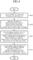
- Fig. 4 is a flow chart showing an overview of the operation of the navigation system 3.
- the functions of the data acquiring unit 30, the coordinate calculating unit 31, the image matching unit 32 and the attitude estimating unit 33 of the navigation system 3 are implemented by a processing circuit.
- the navigation system 3 includes a processing circuit for performing a step ST1 of acquiring distance data, angle data, coordinate data and image data, a step ST2 of calculating the coordinates of a distance measurement point on an image shown by image data by using the distance data, the angle data, the coordinate data and the attitude angles of the airplane 2, a step ST3 of performing image matching on a pair of image data about images shot at different shooting positions, to search for a point corresponding to the coordinates of a distance measurement point on the image shown by one image data of the pair, through the image shown by the other image data of the pair, and a step ST4 of correcting the values of the attitude angles of the airplane 2 in such a way that the difference between the coordinates of the distance measurement point on the image shown by the other image data of the pair and the coordinates of the corresponding point which is searched for by the image matching unit 32 becomes small, to estimate the attitude of the airplane 2, the steps being shown in Fig. 4 .
- the processing circuit can be hardware for exclusive use, or a CPU (Central Processing Unit) that executes a program stored in a memory.
- a CPU Central Processing Unit
- the processing circuit 100 is, for example, a single circuit, a composite circuit, a programmed processor, a parallel programmed processor, an ASIC (Application Specific Integrated Circuit), an FPGA (Field-Programmable Gate Array), or a circuit which is a combination of some of these circuits.
- ASIC Application Specific Integrated Circuit
- FPGA Field-Programmable Gate Array
- each of the following units can be implemented by respective processing circuits, or can be implemented collectively by a single processing circuit.
- the functions of the data acquiring unit 30, the coordinate calculating unit 31, the image matching unit 32 and the attitude estimating unit 33 are implemented by software, firmware or a combination of software and firmware.
- the CPU 101 implements the functions of each of the units by reading and executing programs stored in the memory 102.
- the memory 102 is disposed to store the programs which the CPU executes so as to perform, as a result, the processes of steps ST1 to ST4 shown in Fig. 4 .
- These programs are provided to cause a computer to execute procedures or methods which are carried out by the data acquiring unit 30, the coordinate calculating unit 31, the image matching unit 32 and the attitude estimating unit 33.
- the memory is, for example, a nonvolatile or volatile semiconductor memory, such as a RAM (Random Access Memory), a ROM, a flash memory, an EPROM (Erasable Programmable ROM) or an EEPROM (Electrically EPROM), a magnetic disk, a flexible disk, an optical disk, a compact disk, a mini disk, or a DVD (Digital Versatile Disk).
- a part of the functions of the data acquiring unit 30, the coordinate calculating unit 31, the image matching unit 32 and the attitude estimating unit 33 can be implemented by hardware for exclusive use and another part of the functions can be implemented by software or firmware.
- the processing circuit 100 which is hardware for exclusive use implements the functions of the data acquiring unit 30, and the CPU 101 implements the functions of the coordinate calculating unit 31, the image matching unit 32 and the attitude estimating unit 33 by executing programs stored in the memory 102.
- the above-mentioned processing circuit can implement the above-mentioned functions by using hardware, software, firmware or a combination of some of these elements.
- Fig. 5 illustrates diagrams schematically showing a positional relationship among the left camera 20a, the right camera 20b and the laser distance measuring device 21.
- Fig. 5A is a perspective view of a unit provided with the left camera 20a, the right camera 20b and the laser distance measuring device 21
- Fig. 5B is a diagram showing the unit when viewed from a direction of an X axis
- Fig. 5C is a diagram showing the unit when viewed from a direction of a Z axis
- Fig. 5D is a diagram showing the unit when viewed from a direction of a Y axis. As shown in Fig.
- the left camera 20a is attached to an end of an arm 20c extending leftward from the laser distance measuring device 21, and the right camera 20b is attached to an end of an arm 20d extending rightward from the laser distance measuring device 21.
- the length of each of both the arms 20c and 20d is, for example, 1 m.
- the shooting directions of the left camera 20a and the right camera 20b are oriented toward a vertically downward direction with respect to the airplane 2 (a direction of the Z axis).
- the laser distance measuring device 21 projects laser light from the projection reference point 21a to a distance measurement point P 0 on a ground surface and receives reflected light from the distance measurement point P 0 while changing the projection angle ⁇ of the laser light, to measure the distance 1 from the projection reference point 21a to the distance measurement point P 0 , as shown in Fig. 5B . It is assumed that the projection angle ⁇ at which laser light is projected from the projection reference point 21a toward the vertically downward direction is 90 degrees.
- the left camera 20a and the right camera 20b acquire image data, as will be mentioned below using Fig. 8 , by shooting images of rectangular image shooting areas, as shown in Fig. 5C .
- the position of the projection reference point 21a is the same as that of the airplane 2. Therefore, when the airplane 2 makes a level flight in a direction of the X axis, the unit which configured by the left camera 20a, the right camera 20b and the laser distance measuring device 21 also moves in the direction of the X axis, as shown in Fig. 5D .
- the airplane 2 flies in a state in which the airplane rotates in a rolling direction, in a pitching direction and in a yawing direction.
- Fig. 6 illustrates diagrams showing changes in the positions of the left camera 20a, the right camera 20b and the laser distance measuring device 21, the changes being caused by a flight of the airplane.
- Fig. 6A shows data about the coordinates of the position of the laser distance measuring device 21.
- Fig. 6B is a graph in which the coordinates of the positions of the left camera 20a, the right camera 20b and the laser distance measuring device 21 are plotted on the XZ plane.
- Fig. 6C is a graph in which these position coordinates are plotted on the YZ plane, and
- Fig. 6D is a graph in which these position coordinates are plotted on the XY plane. As shown in Fig.
- the position coordinates of the laser distance measuring device 21 are the position coordinates of the projection reference point 21a which are measured every second by the GNSS device 22.
- the position coordinates of the left camera 20a and the right camera 20b are calculated by assuming that the left camera 20a and the right camera 20b are apart, by the length of each of the arms 20c and 20d which is 1 m, from the position of the projection reference point 21a in directions of the Y axis.
- the positions of the left camera 20a, the right camera 20b and the laser distance measuring device 21 shifted toward a direction of the Z axis.
- Fig. 7 illustrates diagrams showing changes in measurement results acquired by the laser distance measuring device 21, the changes being caused by the flight of the airplane 2, and shows the measurement results acquired when the airplane 2 flew in the state shown in Fig. 6 .
- Fig. 7A shows the angle data and the distance data at each of times
- Fig. 7B is a graph in which the data shown in Fig. 7A are plotted.
- Fig. 8 is a diagram showing images which were shot every second by the left camera 20a and the right camera 20b, and shows the images which were shot when the airplane 2 flew in the state shown in Fig. 6 .
- the measurement results acquired by the laser distance measuring device 21 are stored in the memory card 23 in such a way that each set of a measurement time t, a projection angle ⁇ and a distance 1 is defined as one record.
- the laser distance measuring device 21 performs four measurements per second.
- the projection angle ⁇ is taken in such a manner that the vertical direction downward from the projection reference point 21a, shown in Fig. 5B , is 90 degrees.
- the laser distance measuring device 21 scans the laser light by rotating the projection reference point 21a clockwise in steps of 18 degrees around the X axis when viewed from the positive direction of the X axis.
- left camera images and right camera images as shown in Fig. 8 , which are shot by the left camera image 20a and the right camera 20b, also change dependently on the attitude angles of the airplane 2.
- an error depending on the attitude angles of the airplane 2 occurs between the coordinates of a distance measurement point on an image, the coordinates being calculated using distance data, angle data, coordinate data and image data on the assumption that the airplane 2 makes a level flight, and the coordinates of the same distance measurement point when the airplane 2 actually flies while rotating.
- the attitude angles are corrected in such a way that the above-mentioned error becomes small, and the attitude angles that minimize the above-mentioned error are determined as the estimated values of the attitude angles of the airplane 2.
- the attitude angles that minimize the above-mentioned error are determined as the estimated values of the attitude angles of the airplane 2.
- Fig. 9 is a diagram showing images 100a and 100b which are shot by the left camera 20a and the right camera 20b while the airplane 2 makes a level flight and each of which contains a distance measurement point P 0 of the laser distance measuring device 21. In Fig. 9 , it is assumed that the airplane 2 makes a level flight along with the positive direction of the X axis.
- the laser distance measuring device 21 measures the distance to the distance measurement point P 0 located directly under the airframe of the airplane with the projection angle ⁇ being set to be 90 degrees.
- Fig. 10 is a diagram showing images 100a and 100c which are shot by the left camera 20a and the right camera 20b when the airplane 2 flies while the airplane is tilted in a pitch direction and each of which contains a distance measurement point P 0 of the laser distance measuring device 21.
- the object to be shot is seen at a position close to the right as a whole, as shown by a broken chain line, as compared with the example shown in Fig. 9 .
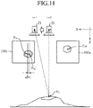
- Fig. 11 is a diagram showing an error occurring between the coordinates of a distance measurement point P 0 on an image, the coordinates being calculated on the assumption that the airplane 2 makes a level flight, and the coordinates of a corresponding point on an image shot when the airplane 2 flies while the airplane is tilted in a pitch direction.
- the coordinates P 0b ' of the point on the image 100c are acquired.
- the pitch angle ⁇ is acquired as an estimated result of the attitude.
- Fig. 12 is a flow chart showing the operation of the navigation system 3 according to Embodiment 1, and shows a series of processes of estimating the attitude angles of the airplane 2 in flight.
- attitude angles of the airplane 2 are expressed by the three parameters including the roll angle ⁇ , the pitch angle ⁇ and the yaw angle ⁇ , and these angles are estimated per second.
- the data acquiring unit 30 reads and acquires distance data, angle data, coordinate data and image data from the memory card 23 mounted in the airplane 2 (step ST1a).
- Each distance data shows the distance 1 measured by the laser distance measuring device 21 from the projection reference point 21a of laser light to a distance measurement point P 0
- each angle data shows the projection angle ⁇ of laser light.
- Each coordinate data shows the three-dimensional coordinates (X 0 , Y 0 , Z 0 ) of the projection reference point 21a of laser light, the three-dimensional coordinates being measured by the GNSS device 22.
- Each image data shows images each containing a distance measurement point P 0 on an object to be shot, the images being shot by the left camera 20a and the right camera 20b.
- the attitude of the airplane 2 can be estimated after the flight has been ended, and by using estimated attitude angles survey results can also be corrected.
- the coordinate calculating unit 31 calculates the three-dimensional coordinates (X, Y, Z) of each distance measurement point P 0 in accordance with the following expression (1) by using the distance data, the angle data and the coordinate data, which are acquired by the data acquiring unit 30, and the settings of the attitude angles ( ⁇ , ⁇ , ⁇ ) of the airplane 2 (step ST2a) .
- a 11 to a 33 denote the elements of a 3 ⁇ 3 rotation matrix showing the inclinations of the laser distance measuring device 21, the left camera 20a and the right camera 20b, the inclinations depending on the attitude of the airplane 2.
- a 11 a 12 a 13 a 21 a 22 a 23 a 31 a 32 a 33 cos ⁇ ⁇ sin ⁇ 0 sin ⁇ cos ⁇ 0 0 0 1 cos ⁇ 0 sin ⁇ 0 1 0 ⁇ sin ⁇ 0 cos ⁇ 1 0 0 0 cos ⁇ ⁇ sin ⁇ 0 sin ⁇ cos ⁇ . .
- (X 0 , Y 0 , Z 0 ) denote the three-dimensional coordinates of the projection reference point 21a of laser light, the three-dimensional coordinates being shown by each of the above-mentioned coordinate data.
- ⁇ denotes the projection angle of the laser light which is shown by the corresponding one of the above-mentioned angle data
- 1 denotes the distance from the projection reference point 21a of the laser light to the distance measurement point P 0 , the distance being shown by the corresponding one of the above-mentioned distance data.
- the projection angle ⁇ is defined by assuming that the vertically downward direction with respect to the airplane 2 makes an angle of 90 degrees.
- the coordinate calculating unit 31 calculates the second-by-second projection center coordinates (X L , Y L , Z L ) of the left camera 20a and the second-by-second projection center coordinates (X R , Y R , Z R ) of the right camera 20b by using the coordinate data and the settings of the attitude angles, in accordance with the following expressions (2) and (3) (step ST3a) .
- the coordinate calculating unit 31 calculates the coordinates (x L , y L ) of a distance measurement point P 0 on a left camera image and the coordinates (x R , y R ) of the distance measurement point P 0 on a right camera image on the basis of the coordinate data, the settings of the attitude angles, the three-dimensional coordinates of the distance measurement point P 0 , the projection center coordinates of the left camera 20a, and the projection center coordinates of the right camera 20b, in accordance with the following expressions (4) and (5) (step ST4a).
- c denotes the focal distance of each of the left and right cameras 20a and 20b.
- U L b 11 X ⁇ X L + b 12 Y ⁇ Y L + b 13 Z ⁇ Z L
- V L b 21 X ⁇ X L + b 22 Y ⁇ Y L + b 23 Z ⁇ Z L
- W L b 31 X ⁇ X L + b 32 Y ⁇ Y L + b 33 Z ⁇ Z L
- U R b 11 X ⁇ X R + b 12 Y ⁇ Y R + b 13 Z ⁇ Z R
- the image matching unit 32 extracts, as a pair, a left camera image shot at a time i and a right camera image shot at a time j later than the time i by +1 from the image data acquired by the data acquiring unit 30.
- the process of extracting a pair of image data which is a target for image matching in this way is referred to as pairing.
- pairing a pair of image data about images which are shot at different shooting positions is acquired.
- the image matching unit 32 searches for a point corresponding to the coordinates (x L , y L ) of a distance measurement point P 0 on the left camera image shot at the time i, the coordinates being calculated by the coordinate calculating unit 31, from the right camera image shot at the time j by performing template matching on the left camera image shot at the time i and the right camera image shot at the time j (step ST5a).
- Fig. 16 shows a correspondence between the coordinates of the distance measurement point P 0 on the left camera image at the time i, and the coordinates of the point corresponding to the coordinates of the distance measurement point and existing on the right camera image shot at the time j, the point being searched for through the template matching.
- SCAN x (x Li , y Li ) denotes the x coordinate of the corresponding point which is searched for by performing template matching on the right camera image shot at the time j with respect to a small region centered at the coordinates (x Li , y Li ) of the distance measurement point P 0 on the left camera image shot at the time i.
- SCAN y (x Li , y Li ) denotes the y coordinate of the corresponding point which is searched for by performing template matching in the same way.
- the above-mentioned coordinates (x Rj , y Rj ) are made to match the above-mentioned coordinates (SCAN x (x Li , y Li ), SCAN y (x Li , y Li )).
- attitude angles which minimize the difference between the above-mentioned pair of coordinates are set as the estimated values of the attitude angles of the airplane 2.
- the attitude estimating unit 33 calculates the correction amounts for the attitude angles which reduce the difference between the coordinates (x Rj , y Rj ) of the distance measurement point P 0 on the right camera image shot at the time j and the coordinates (SCAN x (x Li , y Li ), SCAN y (x Li , y Li )) of the corresponding point which is searched for by the image matching unit 32 (step ST6a) .
- observation equations v x and v y which are shown in the following expression (6) are used.
- tilde ⁇ ( ⁇ ), tilde ⁇ ( ⁇ ⁇ ) and tilde ⁇ ( ⁇ ⁇ ) are approximate solutions of the roll angle ⁇ , the pitch angle ⁇ and the yaw angle ⁇ which are unknown.
- ⁇ , ⁇ , and ⁇ are the correction amounts for the approximate solutions tilde ⁇ , tilde ⁇ and tilde ⁇ .
- ⁇ F x / ⁇ is the partial derivative of F x with respect to the roll angle ⁇
- ⁇ F x / ⁇ is the partial derivative of F x with respect to the pitch angle ⁇
- ⁇ F x / ⁇ is the partial derivative of F x with respect to the yaw angle ⁇ .
- ⁇ F y / ⁇ is the partial derivative of F y with respect to the roll angle ⁇
- ⁇ F y / ⁇ is the partial derivative of F y with respect to the pitch angle ⁇
- ⁇ F y / ⁇ is the partial derivative of F y with respect to the yaw angle ⁇ .
- These partial derivatives are also coefficients whose values are acquired by substitutions of the approximate solutions tilde ⁇ , tilde ⁇ and tilde ⁇ .
- Tilde F x ( ⁇ F x ) is a value which is acquired by substituting SCANx (x L , y L ) and an approximate solution of x R into F x
- tilde F y ( ⁇ F y ) is a value which is acquired by substituting SCAN y (x L , y L ) and an approximate solution of y R into F y .
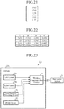
- FIG. 18 A 24 ⁇ 6 design matrix which consists of partial differential coefficients which are calculated for the observation equations in this way is shown in Fig. 18 .
- the attitude estimating unit 33 then calculates the product of the transpose of this design matrix and the design matrix.
- a calculation result acquired using the design matrix shown in Fig. 18 is shown in Fig. 19 .
- the attitude estimating unit 33 further calculates the product of the transpose of this design matrix, and the constant vector shown in Fig. 17 . A result of this calculation is shown in Fig. 20 .
- the attitude estimating unit 33 calculates the product of the inverse matrix calculated from the matrix shown in Fig. 19 , and the vector shown in Fig. 20 .
- a result of this calculation is the correction amounts ( ⁇ , ⁇ , ⁇ ) for the attitude angles shown in Fig. 21 .
- the attitude estimating unit 33 adds the correction amounts which the attitude estimating unit calculates in the above-mentioned way to the previous approximate solutions to correct these approximate solutions, and determines the corrected approximate solutions as the settings of the attitude angles (step ST7a) .
- the attitude estimating unit 33 instructs the coordinate calculating unit 31 to perform the same coordinate calculation as the above-mentioned coordinate calculation.
- the coordinate calculating unit 31 performs the processes in steps ST2a to ST4a by using the corrected approximate solutions as the settings of the attitude angles, and the image matching unit 32 performs the process in step ST5a.
- the attitude estimating unit 33 When the above-mentioned series of processes has been performed the predetermined number of repetitions (when YES in step ST8a), and the correction amounts which minimize the difference between the above-mentioned coordinates are acquired, the attitude estimating unit 33 outputs the approximate solutions which are corrected by using these correction amounts as final estimated results of the attitude angles (step ST9a).
- a pair of a left camera image shot at a time i and a right camera image shot at the time i can be alternatively used. More specifically, according to the present invention, it is sufficient that a pair of image data about images shot at different shooting positions is used.
- stereo image processing for searching for corresponding points between images shot by cameras located at different positions, and acquiring three-dimensional information including the distance to an observation object and depth information, there are a method called fixed stereo and a method called motion stereo.
- two cameras are arranged at a spacing, and images are shot by the cameras. Pairing of a left camera image shot at a time i and a right camera image shot at the time i is equivalent to the fixed stereo.
- the unknown quantities are the three parameters ( ⁇ , ⁇ , ⁇ ) which are the attitude angles at each time
- the six parameters additionally including the position coordinates (X, Y, Z) of the airplane 2 can be alternatively used, or an internal parameter, such as the focal distance c of the cameras, can be included.
- the navigation system 3 pays attention to the fact that the coordinates of corresponding points between images shot at different shooting positions deviate from each other dependently on the attitude of the airplane 2, and corrects the values of the parameters ( ⁇ , ⁇ , ⁇ ) showing the attitude of the airplane 2 in such a way that the difference between these coordinates becomes small, to estimate the attitude of the airplane 2.
- the attitude of the airplane 2 can be estimated even if an IMU and a stabilizer are not used.
- the attitude of the airplane 2 is estimated by using, in addition to image data about an image containing a shot distance measurement point P 0 , the distance 1 from the projection reference point 21a of laser light to the distance measurement point P 0 , the projection angle ⁇ of the laser light and the three-dimensional coordinates (X, Y, Z) of the projection reference point 21a of the laser light, the attitude of the airplane 2 can be estimated with a high degree of accuracy.
- the pair of image data includes image data about an image shot at a time i during a flight of the airplane 2, and image data about an image shot at a time j later than this time i during the flight.
- the pair of image data includes a pair of image data about images shot at a time i by the left camera 20a and the right camera 20b, or a pair of image data about an image shot at a time i by at least one of the left camera 20a and the right cameras 20b and image data about an image shot at a time j later than the time i by at least one of the left and right cameras.
- the navigation system 3 performs the calculation of the coordinates by setting the initial value of the yaw angle ⁇ to zero, the navigation system can acquire an approximate solution of the yaw angle ⁇ from a time series of three-dimensional coordinates which is measured by the GNSS device 22. Therefore, a value calculated from the time series of three-dimensional coordinates measured by the GNSS device 22 can be used as the initial value of the yaw angle ⁇ .
- the survey system 1 is provided with the memory card 23 mounted in the airplane 2.
- the data acquiring unit 30 reads and acquires distance data, angle data, coordinate data and image data which are stored in the memory card 23.
- the attitude of the airplane 2 can be estimated after the flight has been ended, and the survey results can also be corrected by using the estimated attitude angles.
- Fig. 23 is a block diagram showing the configuration of a survey system 1A according to Embodiment 2 of the present invention.
- the survey system 1A surveys geographical features from an airplane 2A, and includes a left camera 20a, a right camera 20b, a laser distance measuring device 21, a GNSS device 22 and a wireless communication device 24 which are mounted in the airplane 2A, and a navigation system 3.
- the wireless communication device 24 transmits distance data, angle data, coordinate data and image data which are acquired during a flight of the airplane 2A to the navigation system 3.
- the navigation system 3 is provided separately from the airplane 2A, as shown in Fig. 23 .
- the navigation system 3 can be mounted in the airplane 2A.
- a data acquiring unit 30 of the navigation system 3 receives and acquires the distance data, the angle data, the coordinate data and the image data which are transmitted by the wireless communication device 24.
- the navigation system 3 estimates the attitude of the airplane 2A by performing the same processing as that shown in Embodiment 1 by using the above-mentioned data which the navigation system acquires in this way.
- the survey system 1A includes the wireless communication device 24 mounted in the airplane 2.
- the data acquiring unit 30 receives and acquires distance data, angle data, coordinate data and image data which are transmitted by the wireless communication device 24.
- the attitude of the airplane 2A can be estimated during a flight of the airplane 2A.
- the survey results can also be corrected during a flight of the airplane 2A by using the estimated attitude angles.
- the navigation system according to the present invention can be implemented as a mobile mapping system, and a vehicle in which this system is mounted is defined as a moving body.
- a railroad car, a ship or a robot can be defined as a moving body, and the navigation system according to the present invention can be used as a device that estimates the attitude of the moving body.
- the attitude angles ( ⁇ , ⁇ , ⁇ ) of the moving body can be used similarly as the parameters showing the attitude of the moving body, and position information can be included in the parameters in some cases.
- the navigation system can estimate the attitude of a moving body with a high degree of accuracy by using a configuration of not including any IMU and any stabilizer, the navigation system is suitable for use as, for example, a navigation system for UAV.
Landscapes
- Engineering & Computer Science (AREA)
- Physics & Mathematics (AREA)
- General Physics & Mathematics (AREA)
- Radar, Positioning & Navigation (AREA)
- Remote Sensing (AREA)
- Electromagnetism (AREA)
- Computer Networks & Wireless Communication (AREA)
- Multimedia (AREA)
- Computer Vision & Pattern Recognition (AREA)
- Theoretical Computer Science (AREA)
- Signal Processing (AREA)
- Aviation & Aerospace Engineering (AREA)
- Length Measuring Devices By Optical Means (AREA)
- Navigation (AREA)
- Optical Radar Systems And Details Thereof (AREA)
Applications Claiming Priority (1)
| Application Number | Priority Date | Filing Date | Title |
|---|---|---|---|
| PCT/JP2015/075598 WO2017042907A1 (fr) | 2015-09-09 | 2015-09-09 | Dispositif de navigation et système de sondage |
Publications (3)
| Publication Number | Publication Date |
|---|---|
| EP3348963A1 true EP3348963A1 (fr) | 2018-07-18 |
| EP3348963A4 EP3348963A4 (fr) | 2019-05-29 |
| EP3348963B1 EP3348963B1 (fr) | 2020-05-20 |
Family
ID=57358823
Family Applications (1)
| Application Number | Title | Priority Date | Filing Date |
|---|---|---|---|
| EP15903572.4A Active EP3348963B1 (fr) | 2015-09-09 | 2015-09-09 | Système de navigation et système de sondage |
Country Status (4)
| Country | Link |
|---|---|
| US (1) | US10222210B2 (fr) |
| EP (1) | EP3348963B1 (fr) |
| JP (1) | JP6029794B1 (fr) |
| WO (1) | WO2017042907A1 (fr) |
Families Citing this family (12)
| Publication number | Priority date | Publication date | Assignee | Title |
|---|---|---|---|---|
| JP6861592B2 (ja) * | 2017-07-14 | 2021-04-21 | 三菱電機株式会社 | データ間引き装置、測量装置、測量システム及びデータ間引き方法 |
| CN107146447A (zh) * | 2017-07-16 | 2017-09-08 | 汤庆佳 | 一种基于无人机的智能车辆管理系统及其方法 |
| CN107478195A (zh) * | 2017-09-15 | 2017-12-15 | 哈尔滨工程大学 | 一种基于光学的空间物体姿态测量装置及其测量方法 |
| CN110268710B (zh) * | 2018-01-07 | 2022-01-04 | 深圳市大疆创新科技有限公司 | 图像数据处理方法、设备、平台及存储介质 |
| JP7188687B2 (ja) * | 2018-07-17 | 2022-12-13 | エアロセンス株式会社 | 情報処理方法、プログラム、および情報処理システム |
| CN109345589A (zh) * | 2018-09-11 | 2019-02-15 | 百度在线网络技术(北京)有限公司 | 基于自动驾驶车辆的位置检测方法、装置、设备及介质 |
| GB201818357D0 (en) * | 2018-11-12 | 2018-12-26 | Forsberg Services Ltd | Locating system |
| JP7241517B2 (ja) * | 2018-12-04 | 2023-03-17 | 三菱電機株式会社 | 航法装置、航法パラメータ計算方法およびプログラム |
| CN110672117B (zh) * | 2019-11-04 | 2022-02-18 | 中国人民解放军空军工程大学 | 基于单观察哨数字望远镜的小航路捷径运动目标航迹获取方法 |
| CN112099521B (zh) * | 2020-10-09 | 2022-05-17 | 北京邮电大学 | 一种无人机路径规划方法及装置 |
| JP2022087978A (ja) * | 2020-12-02 | 2022-06-14 | 三菱電機株式会社 | 位置姿勢算出装置、位置姿勢算出方法及び測量装置 |
| CN117848294B (zh) * | 2023-07-29 | 2024-11-19 | 上海钦天导航技术有限公司 | 测量方法、系统、设备及存储介质 |
Family Cites Families (14)
| Publication number | Priority date | Publication date | Assignee | Title |
|---|---|---|---|---|
| US4335520A (en) * | 1980-09-22 | 1982-06-22 | The United States Of America As Represented By The Secretary Of The Navy | Survey spar system for precision offshore seafloor surveys |
| JP3148900B2 (ja) | 1991-10-25 | 2001-03-26 | 清水建設株式会社 | 模型ヘリコプターを用いる3次元測量システム |
| JPH1151611A (ja) * | 1997-07-31 | 1999-02-26 | Tokyo Electric Power Co Inc:The | 認識対象物体の位置姿勢認識装置および位置姿勢認識方法 |
| JP4480212B2 (ja) | 1999-11-05 | 2010-06-16 | アジア航測株式会社 | 空中写真の位置及び姿勢の計算方法 |
| US20090299635A1 (en) * | 2005-10-13 | 2009-12-03 | Tom Meredydd Brookes | Terrain mapping |
| JP2007240506A (ja) * | 2006-03-06 | 2007-09-20 | Giyourin Cho | 3次元形状と3次元地形計測法 |
| JP4874693B2 (ja) | 2006-04-06 | 2012-02-15 | 株式会社トプコン | 画像処理装置及びその処理方法 |
| DK2227676T3 (en) * | 2007-12-21 | 2017-05-15 | Bae Systems Plc | APPARATUS AND METHOD OF LANDING A ROTOR AIR |
| US10212687B2 (en) * | 2010-09-30 | 2019-02-19 | Echo Ridge Llc | System and method for robust navigation and geolocation using measurements of opportunity |
| JP5992184B2 (ja) | 2012-03-09 | 2016-09-14 | 株式会社トプコン | 画像データ処理装置、画像データ処理方法および画像データ処理用のプログラム |
| JP5561843B1 (ja) * | 2013-01-07 | 2014-07-30 | 株式会社amuse oneself | 制御装置、測量システム、プログラム及び記録媒体並びに計測方法 |
| US9684076B1 (en) * | 2013-03-15 | 2017-06-20 | Daniel Feldkhun | Frequency multiplexed ranging |
| US10643351B2 (en) * | 2013-03-20 | 2020-05-05 | Trimble Inc. | Indoor navigation via multi beam laser projection |
| US9911189B1 (en) * | 2016-06-30 | 2018-03-06 | Kitty Hawk Corporation | Navigation based on downward facing sensors |
-
2015
- 2015-09-09 EP EP15903572.4A patent/EP3348963B1/fr active Active
- 2015-09-09 US US15/561,882 patent/US10222210B2/en active Active
- 2015-09-09 WO PCT/JP2015/075598 patent/WO2017042907A1/fr not_active Ceased
- 2015-09-09 JP JP2016513572A patent/JP6029794B1/ja not_active Expired - Fee Related
Also Published As
| Publication number | Publication date |
|---|---|
| JPWO2017042907A1 (ja) | 2017-09-07 |
| JP6029794B1 (ja) | 2016-11-24 |
| US20180120107A1 (en) | 2018-05-03 |
| EP3348963A4 (fr) | 2019-05-29 |
| EP3348963B1 (fr) | 2020-05-20 |
| US10222210B2 (en) | 2019-03-05 |
| WO2017042907A1 (fr) | 2017-03-16 |
Similar Documents
| Publication | Publication Date | Title |
|---|---|---|
| EP3348963B1 (fr) | Système de navigation et système de sondage | |
| US11099030B2 (en) | Attitude estimation apparatus, attitude estimation method, and observation system | |
| EP3454008B1 (fr) | Dispositif, procédé et programme de traitement de données d'enquête | |
| JP6560337B2 (ja) | 遠隔画像の安定化及び表示 | |
| US8320616B2 (en) | Image-based system and methods for vehicle guidance and navigation | |
| Johnson et al. | Real-time terrain relative navigation test results from a relevant environment for Mars landing | |
| US8649917B1 (en) | Apparatus for measurement of vertical obstructions | |
| US8300096B2 (en) | Apparatus for measurement of vertical obstructions | |
| JP6138326B1 (ja) | 移動体、移動体の制御方法、移動体を制御するプログラム、制御システム、及び情報処理装置 | |
| JP2017053687A (ja) | 飛翔体位置算出システム、飛翔体位置算出方法及び飛翔体位置算出プログラム | |
| KR102620116B1 (ko) | 드론에 의한 타겟 좌표의 취득 시스템 및 이에 의한 타겟 좌표 취득 방법 | |
| KR101911353B1 (ko) | Gnss 신호 손실시 자율 비행 방법 및 이를 위한 무인 비행체 | |
| RU2597024C1 (ru) | Способ оперативного определения угловых элементов внешнего ориентирования космического сканерного снимка | |
| Skaloud et al. | Mapping with MAV: experimental study on the contribution of absolute and relative aerial position control | |
| JP6249864B2 (ja) | 飛翔体の慣性航法システム | |
| US10795158B2 (en) | Method for dual harmonization of a DDP posture-detecting subsystem integrated into a worn/borne head-up viewing system | |
| Andert et al. | Optical aircraft navigation with multi-sensor SLAM and infinite depth features | |
| JP2020071154A (ja) | 位置推定装置、位置推定方法、プログラム、及び記録媒体 | |
| Bukin et al. | A computer vision system for navigation of ground vehicles: Hardware and software | |
| EP3637048A1 (fr) | Dispositif d'amincissement de données, dispositif d'arpentage, système d'arpentage et procédé d'amincissement de données | |
| Ruzgienė | Analysis of camera orientation variation in airborne photogrammetry: images under tilt (roll‑pitch‑yaw) angles | |
| Jia et al. | Modeling image motion in airborne three-line-array (TLA) push-broom cameras | |
| US10964047B2 (en) | Device for locating a target by stellar correction, intended to be on board a mobile carrier | |
| JP2024048738A (ja) | 姿勢角補正装置および姿勢角補正方法 | |
| KR20250141592A (ko) | 비행체의 센서를 보정하는 방법 및 장치 |
Legal Events
| Date | Code | Title | Description |
|---|---|---|---|
| STAA | Information on the status of an ep patent application or granted ep patent |
Free format text: STATUS: THE INTERNATIONAL PUBLICATION HAS BEEN MADE |
|
| PUAI | Public reference made under article 153(3) epc to a published international application that has entered the european phase |
Free format text: ORIGINAL CODE: 0009012 |
|
| STAA | Information on the status of an ep patent application or granted ep patent |
Free format text: STATUS: REQUEST FOR EXAMINATION WAS MADE |
|
| 17P | Request for examination filed |
Effective date: 20171121 |
|
| AK | Designated contracting states |
Kind code of ref document: A1 Designated state(s): AL AT BE BG CH CY CZ DE DK EE ES FI FR GB GR HR HU IE IS IT LI LT LU LV MC MK MT NL NO PL PT RO RS SE SI SK SM TR |
|
| AX | Request for extension of the european patent |
Extension state: BA ME |
|
| DAV | Request for validation of the european patent (deleted) | ||
| DAX | Request for extension of the european patent (deleted) | ||
| REG | Reference to a national code |
Ref country code: DE Ref legal event code: R079 Ref document number: 602015053203 Country of ref document: DE Free format text: PREVIOUS MAIN CLASS: G01C0011060000 Ipc: B64D0047080000 |
|
| A4 | Supplementary search report drawn up and despatched |
Effective date: 20190502 |
|
| RIC1 | Information provided on ipc code assigned before grant |
Ipc: G01C 1/04 20060101ALI20190425BHEP Ipc: G01S 17/42 20060101ALI20190425BHEP Ipc: G06T 7/593 20170101ALI20190425BHEP Ipc: B64D 47/08 20060101AFI20190425BHEP Ipc: G01S 17/02 20060101ALI20190425BHEP Ipc: H04N 7/18 20060101ALI20190425BHEP |
|
| GRAP | Despatch of communication of intention to grant a patent |
Free format text: ORIGINAL CODE: EPIDOSNIGR1 |
|
| STAA | Information on the status of an ep patent application or granted ep patent |
Free format text: STATUS: GRANT OF PATENT IS INTENDED |
|
| INTG | Intention to grant announced |
Effective date: 20191122 |
|
| GRAS | Grant fee paid |
Free format text: ORIGINAL CODE: EPIDOSNIGR3 |
|
| GRAA | (expected) grant |
Free format text: ORIGINAL CODE: 0009210 |
|
| STAA | Information on the status of an ep patent application or granted ep patent |
Free format text: STATUS: THE PATENT HAS BEEN GRANTED |
|
| AK | Designated contracting states |
Kind code of ref document: B1 Designated state(s): AL AT BE BG CH CY CZ DE DK EE ES FI FR GB GR HR HU IE IS IT LI LT LU LV MC MK MT NL NO PL PT RO RS SE SI SK SM TR |
|
| REG | Reference to a national code |
Ref country code: GB Ref legal event code: FG4D |
|
| REG | Reference to a national code |
Ref country code: CH Ref legal event code: EP |
|
| REG | Reference to a national code |
Ref country code: DE Ref legal event code: R096 Ref document number: 602015053203 Country of ref document: DE |
|
| REG | Reference to a national code |
Ref country code: AT Ref legal event code: REF Ref document number: 1272463 Country of ref document: AT Kind code of ref document: T Effective date: 20200615 |
|
| REG | Reference to a national code |
Ref country code: LT Ref legal event code: MG4D |
|
| REG | Reference to a national code |
Ref country code: NL Ref legal event code: MP Effective date: 20200520 |
|
| PG25 | Lapsed in a contracting state [announced via postgrant information from national office to epo] |
Ref country code: IS Free format text: LAPSE BECAUSE OF FAILURE TO SUBMIT A TRANSLATION OF THE DESCRIPTION OR TO PAY THE FEE WITHIN THE PRESCRIBED TIME-LIMIT Effective date: 20200920 Ref country code: PT Free format text: LAPSE BECAUSE OF FAILURE TO SUBMIT A TRANSLATION OF THE DESCRIPTION OR TO PAY THE FEE WITHIN THE PRESCRIBED TIME-LIMIT Effective date: 20200921 Ref country code: NO Free format text: LAPSE BECAUSE OF FAILURE TO SUBMIT A TRANSLATION OF THE DESCRIPTION OR TO PAY THE FEE WITHIN THE PRESCRIBED TIME-LIMIT Effective date: 20200820 Ref country code: FI Free format text: LAPSE BECAUSE OF FAILURE TO SUBMIT A TRANSLATION OF THE DESCRIPTION OR TO PAY THE FEE WITHIN THE PRESCRIBED TIME-LIMIT Effective date: 20200520 Ref country code: GR Free format text: LAPSE BECAUSE OF FAILURE TO SUBMIT A TRANSLATION OF THE DESCRIPTION OR TO PAY THE FEE WITHIN THE PRESCRIBED TIME-LIMIT Effective date: 20200821 Ref country code: SE Free format text: LAPSE BECAUSE OF FAILURE TO SUBMIT A TRANSLATION OF THE DESCRIPTION OR TO PAY THE FEE WITHIN THE PRESCRIBED TIME-LIMIT Effective date: 20200520 Ref country code: LT Free format text: LAPSE BECAUSE OF FAILURE TO SUBMIT A TRANSLATION OF THE DESCRIPTION OR TO PAY THE FEE WITHIN THE PRESCRIBED TIME-LIMIT Effective date: 20200520 |
|
| PG25 | Lapsed in a contracting state [announced via postgrant information from national office to epo] |
Ref country code: BG Free format text: LAPSE BECAUSE OF FAILURE TO SUBMIT A TRANSLATION OF THE DESCRIPTION OR TO PAY THE FEE WITHIN THE PRESCRIBED TIME-LIMIT Effective date: 20200820 Ref country code: RS Free format text: LAPSE BECAUSE OF FAILURE TO SUBMIT A TRANSLATION OF THE DESCRIPTION OR TO PAY THE FEE WITHIN THE PRESCRIBED TIME-LIMIT Effective date: 20200520 Ref country code: LV Free format text: LAPSE BECAUSE OF FAILURE TO SUBMIT A TRANSLATION OF THE DESCRIPTION OR TO PAY THE FEE WITHIN THE PRESCRIBED TIME-LIMIT Effective date: 20200520 Ref country code: HR Free format text: LAPSE BECAUSE OF FAILURE TO SUBMIT A TRANSLATION OF THE DESCRIPTION OR TO PAY THE FEE WITHIN THE PRESCRIBED TIME-LIMIT Effective date: 20200520 |
|
| REG | Reference to a national code |
Ref country code: AT Ref legal event code: MK05 Ref document number: 1272463 Country of ref document: AT Kind code of ref document: T Effective date: 20200520 |
|
| PG25 | Lapsed in a contracting state [announced via postgrant information from national office to epo] |
Ref country code: NL Free format text: LAPSE BECAUSE OF FAILURE TO SUBMIT A TRANSLATION OF THE DESCRIPTION OR TO PAY THE FEE WITHIN THE PRESCRIBED TIME-LIMIT Effective date: 20200520 Ref country code: AL Free format text: LAPSE BECAUSE OF FAILURE TO SUBMIT A TRANSLATION OF THE DESCRIPTION OR TO PAY THE FEE WITHIN THE PRESCRIBED TIME-LIMIT Effective date: 20200520 |
|
| PG25 | Lapsed in a contracting state [announced via postgrant information from national office to epo] |
Ref country code: DK Free format text: LAPSE BECAUSE OF FAILURE TO SUBMIT A TRANSLATION OF THE DESCRIPTION OR TO PAY THE FEE WITHIN THE PRESCRIBED TIME-LIMIT Effective date: 20200520 Ref country code: SM Free format text: LAPSE BECAUSE OF FAILURE TO SUBMIT A TRANSLATION OF THE DESCRIPTION OR TO PAY THE FEE WITHIN THE PRESCRIBED TIME-LIMIT Effective date: 20200520 Ref country code: EE Free format text: LAPSE BECAUSE OF FAILURE TO SUBMIT A TRANSLATION OF THE DESCRIPTION OR TO PAY THE FEE WITHIN THE PRESCRIBED TIME-LIMIT Effective date: 20200520 Ref country code: AT Free format text: LAPSE BECAUSE OF FAILURE TO SUBMIT A TRANSLATION OF THE DESCRIPTION OR TO PAY THE FEE WITHIN THE PRESCRIBED TIME-LIMIT Effective date: 20200520 Ref country code: CZ Free format text: LAPSE BECAUSE OF FAILURE TO SUBMIT A TRANSLATION OF THE DESCRIPTION OR TO PAY THE FEE WITHIN THE PRESCRIBED TIME-LIMIT Effective date: 20200520 Ref country code: IT Free format text: LAPSE BECAUSE OF FAILURE TO SUBMIT A TRANSLATION OF THE DESCRIPTION OR TO PAY THE FEE WITHIN THE PRESCRIBED TIME-LIMIT Effective date: 20200520 Ref country code: RO Free format text: LAPSE BECAUSE OF FAILURE TO SUBMIT A TRANSLATION OF THE DESCRIPTION OR TO PAY THE FEE WITHIN THE PRESCRIBED TIME-LIMIT Effective date: 20200520 Ref country code: ES Free format text: LAPSE BECAUSE OF FAILURE TO SUBMIT A TRANSLATION OF THE DESCRIPTION OR TO PAY THE FEE WITHIN THE PRESCRIBED TIME-LIMIT Effective date: 20200520 |
|
| REG | Reference to a national code |
Ref country code: DE Ref legal event code: R097 Ref document number: 602015053203 Country of ref document: DE |
|
| PG25 | Lapsed in a contracting state [announced via postgrant information from national office to epo] |
Ref country code: PL Free format text: LAPSE BECAUSE OF FAILURE TO SUBMIT A TRANSLATION OF THE DESCRIPTION OR TO PAY THE FEE WITHIN THE PRESCRIBED TIME-LIMIT Effective date: 20200520 Ref country code: SK Free format text: LAPSE BECAUSE OF FAILURE TO SUBMIT A TRANSLATION OF THE DESCRIPTION OR TO PAY THE FEE WITHIN THE PRESCRIBED TIME-LIMIT Effective date: 20200520 |
|
| PLBE | No opposition filed within time limit |
Free format text: ORIGINAL CODE: 0009261 |
|
| STAA | Information on the status of an ep patent application or granted ep patent |
Free format text: STATUS: NO OPPOSITION FILED WITHIN TIME LIMIT |
|
| 26N | No opposition filed |
Effective date: 20210223 |
|
| REG | Reference to a national code |
Ref country code: CH Ref legal event code: PL |
|
| PG25 | Lapsed in a contracting state [announced via postgrant information from national office to epo] |
Ref country code: SI Free format text: LAPSE BECAUSE OF FAILURE TO SUBMIT A TRANSLATION OF THE DESCRIPTION OR TO PAY THE FEE WITHIN THE PRESCRIBED TIME-LIMIT Effective date: 20200520 |
|
| REG | Reference to a national code |
Ref country code: BE Ref legal event code: MM Effective date: 20200930 |
|
| PG25 | Lapsed in a contracting state [announced via postgrant information from national office to epo] |
Ref country code: LU Free format text: LAPSE BECAUSE OF NON-PAYMENT OF DUE FEES Effective date: 20200909 |
|
| PG25 | Lapsed in a contracting state [announced via postgrant information from national office to epo] |
Ref country code: LI Free format text: LAPSE BECAUSE OF NON-PAYMENT OF DUE FEES Effective date: 20200930 Ref country code: IE Free format text: LAPSE BECAUSE OF NON-PAYMENT OF DUE FEES Effective date: 20200909 Ref country code: BE Free format text: LAPSE BECAUSE OF NON-PAYMENT OF DUE FEES Effective date: 20200930 Ref country code: CH Free format text: LAPSE BECAUSE OF NON-PAYMENT OF DUE FEES Effective date: 20200930 |
|
| PG25 | Lapsed in a contracting state [announced via postgrant information from national office to epo] |
Ref country code: TR Free format text: LAPSE BECAUSE OF FAILURE TO SUBMIT A TRANSLATION OF THE DESCRIPTION OR TO PAY THE FEE WITHIN THE PRESCRIBED TIME-LIMIT Effective date: 20200520 Ref country code: MT Free format text: LAPSE BECAUSE OF FAILURE TO SUBMIT A TRANSLATION OF THE DESCRIPTION OR TO PAY THE FEE WITHIN THE PRESCRIBED TIME-LIMIT Effective date: 20200520 Ref country code: CY Free format text: LAPSE BECAUSE OF FAILURE TO SUBMIT A TRANSLATION OF THE DESCRIPTION OR TO PAY THE FEE WITHIN THE PRESCRIBED TIME-LIMIT Effective date: 20200520 |
|
| PG25 | Lapsed in a contracting state [announced via postgrant information from national office to epo] |
Ref country code: MK Free format text: LAPSE BECAUSE OF FAILURE TO SUBMIT A TRANSLATION OF THE DESCRIPTION OR TO PAY THE FEE WITHIN THE PRESCRIBED TIME-LIMIT Effective date: 20200520 Ref country code: MC Free format text: LAPSE BECAUSE OF FAILURE TO SUBMIT A TRANSLATION OF THE DESCRIPTION OR TO PAY THE FEE WITHIN THE PRESCRIBED TIME-LIMIT Effective date: 20200520 |
|
| REG | Reference to a national code |
Ref country code: DE Ref legal event code: R084 Ref document number: 602015053203 Country of ref document: DE |
|
| REG | Reference to a national code |
Ref country code: GB Ref legal event code: 746 Effective date: 20221229 |
|
| P01 | Opt-out of the competence of the unified patent court (upc) registered |
Effective date: 20230512 |
|
| PGFP | Annual fee paid to national office [announced via postgrant information from national office to epo] |
Ref country code: GB Payment date: 20230727 Year of fee payment: 9 |
|
| PGFP | Annual fee paid to national office [announced via postgrant information from national office to epo] |
Ref country code: FR Payment date: 20230808 Year of fee payment: 9 Ref country code: DE Payment date: 20230802 Year of fee payment: 9 |
|
| REG | Reference to a national code |
Ref country code: DE Ref legal event code: R119 Ref document number: 602015053203 Country of ref document: DE |
|
| GBPC | Gb: european patent ceased through non-payment of renewal fee |
Effective date: 20240909 |
|
| PG25 | Lapsed in a contracting state [announced via postgrant information from national office to epo] |
Ref country code: DE Free format text: LAPSE BECAUSE OF NON-PAYMENT OF DUE FEES Effective date: 20250401 |
|
| PG25 | Lapsed in a contracting state [announced via postgrant information from national office to epo] |
Ref country code: GB Free format text: LAPSE BECAUSE OF NON-PAYMENT OF DUE FEES Effective date: 20240909 |
|
| PG25 | Lapsed in a contracting state [announced via postgrant information from national office to epo] |
Ref country code: FR Free format text: LAPSE BECAUSE OF NON-PAYMENT OF DUE FEES Effective date: 20240930 |