EP3349042B1 - Capteur de surveillance et véhicule relié par le plancher - Google Patents
Capteur de surveillance et véhicule relié par le plancher Download PDFInfo
- Publication number
- EP3349042B1 EP3349042B1 EP17150936.7A EP17150936A EP3349042B1 EP 3349042 B1 EP3349042 B1 EP 3349042B1 EP 17150936 A EP17150936 A EP 17150936A EP 3349042 B1 EP3349042 B1 EP 3349042B1
- Authority
- EP
- European Patent Office
- Prior art keywords
- light
- monitoring sensor
- scanning
- optics
- line
- Prior art date
- Legal status (The legal status is an assumption and is not a legal conclusion. Google has not performed a legal analysis and makes no representation as to the accuracy of the status listed.)
- Active
Links
Images

Classifications
-
- G—PHYSICS
- G01—MEASURING; TESTING
- G01S—RADIO DIRECTION-FINDING; RADIO NAVIGATION; DETERMINING DISTANCE OR VELOCITY BY USE OF RADIO WAVES; LOCATING OR PRESENCE-DETECTING BY USE OF THE REFLECTION OR RERADIATION OF RADIO WAVES; ANALOGOUS ARRANGEMENTS USING OTHER WAVES
- G01S7/00—Details of systems according to groups G01S13/00, G01S15/00, G01S17/00
- G01S7/48—Details of systems according to groups G01S13/00, G01S15/00, G01S17/00 of systems according to group G01S17/00
- G01S7/497—Means for monitoring or calibrating
- G01S7/4972—Alignment of sensor
-
- G—PHYSICS
- G01—MEASURING; TESTING
- G01S—RADIO DIRECTION-FINDING; RADIO NAVIGATION; DETERMINING DISTANCE OR VELOCITY BY USE OF RADIO WAVES; LOCATING OR PRESENCE-DETECTING BY USE OF THE REFLECTION OR RERADIATION OF RADIO WAVES; ANALOGOUS ARRANGEMENTS USING OTHER WAVES
- G01S17/00—Systems using the reflection or reradiation of electromagnetic waves other than radio waves, e.g. lidar systems
- G01S17/02—Systems using the reflection of electromagnetic waves other than radio waves
- G01S17/04—Systems determining the presence of a target
-
- G—PHYSICS
- G01—MEASURING; TESTING
- G01S—RADIO DIRECTION-FINDING; RADIO NAVIGATION; DETERMINING DISTANCE OR VELOCITY BY USE OF RADIO WAVES; LOCATING OR PRESENCE-DETECTING BY USE OF THE REFLECTION OR RERADIATION OF RADIO WAVES; ANALOGOUS ARRANGEMENTS USING OTHER WAVES
- G01S17/00—Systems using the reflection or reradiation of electromagnetic waves other than radio waves, e.g. lidar systems
- G01S17/02—Systems using the reflection of electromagnetic waves other than radio waves
- G01S17/06—Systems determining position data of a target
- G01S17/46—Indirect determination of position data
- G01S17/48—Active triangulation systems, i.e. using the transmission and reflection of electromagnetic waves other than radio waves
-
- G—PHYSICS
- G01—MEASURING; TESTING
- G01S—RADIO DIRECTION-FINDING; RADIO NAVIGATION; DETERMINING DISTANCE OR VELOCITY BY USE OF RADIO WAVES; LOCATING OR PRESENCE-DETECTING BY USE OF THE REFLECTION OR RERADIATION OF RADIO WAVES; ANALOGOUS ARRANGEMENTS USING OTHER WAVES
- G01S17/00—Systems using the reflection or reradiation of electromagnetic waves other than radio waves, e.g. lidar systems
- G01S17/88—Lidar systems specially adapted for specific applications
- G01S17/89—Lidar systems specially adapted for specific applications for mapping or imaging
- G01S17/90—Lidar systems specially adapted for specific applications for mapping or imaging using synthetic aperture techniques
-
- G—PHYSICS
- G01—MEASURING; TESTING
- G01S—RADIO DIRECTION-FINDING; RADIO NAVIGATION; DETERMINING DISTANCE OR VELOCITY BY USE OF RADIO WAVES; LOCATING OR PRESENCE-DETECTING BY USE OF THE REFLECTION OR RERADIATION OF RADIO WAVES; ANALOGOUS ARRANGEMENTS USING OTHER WAVES
- G01S17/00—Systems using the reflection or reradiation of electromagnetic waves other than radio waves, e.g. lidar systems
- G01S17/88—Lidar systems specially adapted for specific applications
- G01S17/93—Lidar systems specially adapted for specific applications for anti-collision purposes
- G01S17/931—Lidar systems specially adapted for specific applications for anti-collision purposes of land vehicles
-
- G—PHYSICS
- G01—MEASURING; TESTING
- G01S—RADIO DIRECTION-FINDING; RADIO NAVIGATION; DETERMINING DISTANCE OR VELOCITY BY USE OF RADIO WAVES; LOCATING OR PRESENCE-DETECTING BY USE OF THE REFLECTION OR RERADIATION OF RADIO WAVES; ANALOGOUS ARRANGEMENTS USING OTHER WAVES
- G01S7/00—Details of systems according to groups G01S13/00, G01S15/00, G01S17/00
- G01S7/48—Details of systems according to groups G01S13/00, G01S15/00, G01S17/00 of systems according to group G01S17/00
- G01S7/481—Constructional features, e.g. arrangements of optical elements
- G01S7/4811—Constructional features, e.g. arrangements of optical elements common to transmitter and receiver
-
- G—PHYSICS
- G01—MEASURING; TESTING
- G01S—RADIO DIRECTION-FINDING; RADIO NAVIGATION; DETERMINING DISTANCE OR VELOCITY BY USE OF RADIO WAVES; LOCATING OR PRESENCE-DETECTING BY USE OF THE REFLECTION OR RERADIATION OF RADIO WAVES; ANALOGOUS ARRANGEMENTS USING OTHER WAVES
- G01S7/00—Details of systems according to groups G01S13/00, G01S15/00, G01S17/00
- G01S7/48—Details of systems according to groups G01S13/00, G01S15/00, G01S17/00 of systems according to group G01S17/00
- G01S7/481—Constructional features, e.g. arrangements of optical elements
- G01S7/4814—Constructional features, e.g. arrangements of optical elements of transmitters alone
-
- G—PHYSICS
- G01—MEASURING; TESTING
- G01S—RADIO DIRECTION-FINDING; RADIO NAVIGATION; DETERMINING DISTANCE OR VELOCITY BY USE OF RADIO WAVES; LOCATING OR PRESENCE-DETECTING BY USE OF THE REFLECTION OR RERADIATION OF RADIO WAVES; ANALOGOUS ARRANGEMENTS USING OTHER WAVES
- G01S7/00—Details of systems according to groups G01S13/00, G01S15/00, G01S17/00
- G01S7/48—Details of systems according to groups G01S13/00, G01S15/00, G01S17/00 of systems according to group G01S17/00
- G01S7/481—Constructional features, e.g. arrangements of optical elements
- G01S7/4817—Constructional features, e.g. arrangements of optical elements relating to scanning
-
- G—PHYSICS
- G01—MEASURING; TESTING
- G01S—RADIO DIRECTION-FINDING; RADIO NAVIGATION; DETERMINING DISTANCE OR VELOCITY BY USE OF RADIO WAVES; LOCATING OR PRESENCE-DETECTING BY USE OF THE REFLECTION OR RERADIATION OF RADIO WAVES; ANALOGOUS ARRANGEMENTS USING OTHER WAVES
- G01S7/00—Details of systems according to groups G01S13/00, G01S15/00, G01S17/00
- G01S7/48—Details of systems according to groups G01S13/00, G01S15/00, G01S17/00 of systems according to group G01S17/00
- G01S7/483—Details of pulse systems
- G01S7/486—Receivers
- G01S7/4865—Time delay measurement, e.g. time-of-flight measurement, time of arrival measurement or determining the exact position of a peak
-
- G—PHYSICS
- G05—CONTROLLING; REGULATING
- G05D—SYSTEMS FOR CONTROLLING OR REGULATING NON-ELECTRIC VARIABLES
- G05D1/00—Control of position, course, altitude or attitude of land, water, air or space vehicles, e.g. using automatic pilots
- G05D1/20—Control system inputs
- G05D1/24—Arrangements for determining position or orientation
- G05D1/242—Means based on the reflection of waves generated by the vehicle
-
- G—PHYSICS
- G05—CONTROLLING; REGULATING
- G05D—SYSTEMS FOR CONTROLLING OR REGULATING NON-ELECTRIC VARIABLES
- G05D1/00—Control of position, course, altitude or attitude of land, water, air or space vehicles, e.g. using automatic pilots
- G05D1/60—Intended control result
- G05D1/617—Safety or protection, e.g. defining protection zones around obstacles or avoiding hazards
- G05D1/622—Obstacle avoidance
-
- G—PHYSICS
- G08—SIGNALLING
- G08G—TRAFFIC CONTROL SYSTEMS
- G08G1/00—Traffic control systems for road vehicles
- G08G1/16—Anti-collision systems
-
- G—PHYSICS
- G05—CONTROLLING; REGULATING
- G05D—SYSTEMS FOR CONTROLLING OR REGULATING NON-ELECTRIC VARIABLES
- G05D2105/00—Specific applications of the controlled vehicles
- G05D2105/20—Specific applications of the controlled vehicles for transportation
- G05D2105/28—Specific applications of the controlled vehicles for transportation of freight
-
- G—PHYSICS
- G05—CONTROLLING; REGULATING
- G05D—SYSTEMS FOR CONTROLLING OR REGULATING NON-ELECTRIC VARIABLES
- G05D2107/00—Specific environments of the controlled vehicles
- G05D2107/70—Industrial sites, e.g. warehouses or factories
-
- G—PHYSICS
- G05—CONTROLLING; REGULATING
- G05D—SYSTEMS FOR CONTROLLING OR REGULATING NON-ELECTRIC VARIABLES
- G05D2109/00—Types of controlled vehicles
- G05D2109/10—Land vehicles
-
- G—PHYSICS
- G05—CONTROLLING; REGULATING
- G05D—SYSTEMS FOR CONTROLLING OR REGULATING NON-ELECTRIC VARIABLES
- G05D2111/00—Details of signals used for control of position, course, altitude or attitude of land, water, air or space vehicles
- G05D2111/10—Optical signals
- G05D2111/17—Coherent light, e.g. laser signals
Definitions
- laser scanners are used for this purpose.
- Such laser scanners usually have movable optics and devices for light transit time measurement, which is associated with high costs.
- the distance of an existing object or obstacle in the monitoring area can be determined.
- the light generated by the light source of the light emitter is focused with the aid of the transmitting optics to form a transmitted light beam, which strikes in the monitoring area on an optionally located there, to be detected object.
- the transmitted light may be remitted from such an object, i. diffused or specularly reflected. It passes through a receiving optical system and can be detected by a light receiver, which forms a receiving unit together with the receiving optics.
- the light receiver consists in known solutions of an array of photosensitive receiver elements.
- the position of a light spot generated by the remitted light on the light receiver changes in the so-called triangulation direction.
- the point of impact on the light receiver and the distance of the detected object.
- a monitoring sensor can be mounted on a vehicle, wherein the monitoring sensor is expediently arranged at a distance from the track to be monitored and oriented such that the transmitted light is emitted obliquely at a predetermined angle of inclination in the direction of the travel path and there at a corresponding distance from the monitoring sensor.
- the track thus provides a The monitoring area extends between the monitoring sensor and the point of impact of the transmitted light on the scanning plane.
- the transmitted light hits an object in the monitoring area, which is closer to the monitoring sensor than the point of incidence of the transmitted light on the scanning plane, the transmitted light which passes through the receiving optical system is reflected at a different angle in the direction of the receiving optics, so that shifts the position of the light spot generated from the remitted light in the triangulation direction on the light receiver.
- the transmitted light can be widened laterally, so that it generates a scanning light line when hitting the scanning plane or generally on an imaginary screen, which is transverse to the viewing direction of the monitoring sensor and thus usually transverse to the direction of travel of the vehicle and extends parallel to the scanning plane.
- the transmitted light is fan-shaped, so to speak, so that the monitoring area extends sector-shaped from the monitoring sensor.
- the light emitter, the light receiver and the receiving optics are designed and aligned such that the scanning light line on the scanning plane runs as a straight line across the main monitoring direction of the monitoring sensor, which is imaged as a rectilinear spot on the light receiver in the absence of obstacles, this rectilinear image parallel to the rows or columns of the light receiver, in which the receiver elements are arranged.
- a lateral position on the light receiver ie a position in the direction of extension of the line-shaped light spot, corresponds to this a respective angular position within the sector-shaped monitoring area.
- the incident location of the light received from the corresponding angle shifts transversely, in particular perpendicularly, to the extending direction of the light spot on the light receiver.
- a short segment of the line-shaped receiving light spot is offset transversely to the extension direction of that rectilinear receiving light spot which would be generated without the presence of objects in the surveillance area.
- the main monitoring direction usually coincides with the direction of travel of a vehicle carrying the monitoring sensor.
- the object is achieved by a monitoring sensor having the features of claim 1 and by a vehicle having the features of claim 9.
- the transmitting optics is set up to focus the light emitted by the light source into a transmitted light bundle which, when impinging on a scanning plane which is inclined to the optical axis of the transmitting optics by a predetermined angle of inclination in the triangulation direction, generates a scanning light line, which is concave curved viewed from the direction of the monitoring sensor.
- the receiver elements are advantageously arranged in the form of a two-dimensional array and are adapted to convert received light into electrical received signals.
- An evaluation unit for generating a detection signal from the received signals can be provided.
- light receivers and light transmitters can be spaced apart in the triangulation direction, so that the beam paths of the transmitted light and of the received light have a parallax relative to one another.
- the named scanning plane can be regarded as a fictitious reference plane.
- the scanning plane for example, a real area, such as a track to be monitored correspond, which does not necessarily have to be exactly flat due to local conditions.
- Said angle of inclination usually depends on the distance of the monitoring sensor from the scanning plane, ie the height of the attachment point of the monitoring sensor on the vehicle over the travel of the vehicle, and the desired maximum extent of the monitoring range corresponding to the distance of the scanning light line from the monitoring sensor.
- the monitoring sensor is designed or oriented such that the triangulation direction transversely, advantageously perpendicular, extends to the scanning plane.
- An inclination of the triangulation direction with respect to the scanning plane deviating from a perpendicular of the scanning plane is advantageously provided only within a plane which is perpendicular to the scanning plane and comprises the optical axis of the transmitting optics.
- the desired curvature of the scanning light line is advantageously achieved in that the transmitting optics directs extra-axial beams with increasing lateral angular distance from the optical axis of the transmitting optics more strongly downwards in the direction of the scanning plane.
- lateral subareas of the surveillance area i. Subareas that are located laterally to the main monitoring direction are better monitored.
- it would potentially also be possible to monitor these lateral areas by producing a sufficiently long rectilinear scanning light line, so that a suitable solid angle range is covered.
- the problem that with increasing angles of incidence of the transmitted light on the scanning plane is always further away from the monitoring sensor and the transmitted light thus impinges at an ever flatter angle to the scanning plane.
- no sufficient amount of light is remitted from these places in the direction of the light receiver, so that a reliable detection of remitted light by the light receiver in these outer areas is no longer guaranteed.
- the course of the scanning light line on the scanning plane corresponds to a segment of a circle, a parabola, a hyperbola or an ellipse.
- the aperture angle of the scanned sector-shaped region i. the angular range over which the monitoring area extends is advantageously at least 45 °, preferably at least 90 ° and in particular up to 180 °.
- the transmitted light bundle focused by the transmission optics generates a curved reference light line in projection onto a reference scanning plane extending perpendicular to the optical axis of the transmitting optics.
- the profile of the reference light line can serve as a reference for the design of the transmitting or receiving optics, so that it is possible in particular to simplify the computation steps required for calculating the optics.
- the vertex of the reference light line advantageously corresponds to the intersection of the optical axis of the transmitting optics with the reference scanning plane.
- the intensity distribution of the scanning light line in the longitudinal direction and / or in the transverse direction of the scanning light line is homogeneous.
- An appropriate design of the transmission optics ensures that, on the one hand, the image of the scanning light line on the light receiver, ie the light spot, is as sharply delimited as possible and, on the other hand a homogeneous distribution of intensity of the light spot over its entire length is given. This enables reliable object detection over the entire surveillance area.
- the receiving optics is adapted to generate a straight line corresponding image of the scanning light line on the light receiver.
- a rectilinear image of the scanning light line on the light receiver is modeled that the transmitted light impinges on a flat scanning plane, so that no distortions occur in the curvature of the scanning light line.
- the receiving optics makes, so to speak, the distortions of the transmitting optics "reversed", which are necessary in order to convert about an imaginary rectilinear scanning light line in the concave curved scanning light line according to the invention.
- an equally curved light spot would form on the light receiver, which would make the evaluation of a picture produced by the light receiver more complex, since it would no longer be e.g. only a maximum of the light distribution could be determined line by line or column by column, but radial components would have to be considered in the distance determination.
- the photosensitive surface of the light receiver is optimally utilized.
- the generation of a light spot in the form of a rectilinear image of the scanning light line also has the advantage that the variation of the light spot position on the light receiver as a function of the distance of an object to be detected from the monitoring sensor is largely the same regardless of the angular position of the object.
- the receiver elements of the light receiver are arranged in rows and columns, wherein the image of the scanning light line on the light receiver parallel to the rows or columns.
- the evaluation of the image generated by the light receiver is further facilitated.
- the transmitting optics and / or the receiving optics each comprise at least one lens, wherein at least one refractive surface of the lens is designed as a free-form surface.
- at least one refractive surface is designed as a freeform surface.
- the desired distortions can be achieved in a simple and cost-effective manner when generating the scanning light line or when producing an image of the scanning light line on the light receiver.
- the transmitting and / or the receiving optics are designed as mirror optics or comprise a respective combination of one or more mirror optics and one or more lenses.
- the transmitting optics and / or the receiving optics can each comprise at least one mirror optics whose light-reflecting surface is designed as a free-form surface.
- the transmitting optics has at least two free-form surfaces, wherein a first free-form surface is configured in such a way that it would produce a straight scanning line on the scanning plane and a second free-form surface is configured such that it causes the curvature of the scanning light line.
- the first free-form surface thus effects a collimation of the transmitted light in the triangulation direction and a spreading of the transmitted light in the direction of the opening angle.
- the second free-form surface serves to deflect off-axis beams with increasing lateral angular distance from the optical axis of the transmitting optics more strongly downwards in the direction of the scanning plane in order to generate the desired curvature of the scanning light line.
- the free-form surfaces can be provided on one or even on several lenses.
- the two refractive surfaces of a single lens may be formed as a respective free-form surface.
- the present invention also extends to a field-bound vehicle, in particular a driverless transport vehicle, having a monitoring sensor according to at least one of the aforementioned embodiments for monitoring a travel path of the vehicle.
- the monitoring sensor is spaced apart from the track to be monitored on the vehicle and aligned such that the optical axis of the transmission optics intersects a flat track at a predetermined distance from the vehicle.
- Fig. 1 and 2 show a floor-bound vehicle 10, which can travel along a travel path 26 in a direction of movement RF.
- a monitoring sensor 12 for the spatially resolved detection of objects in a monitoring area 20 is arranged on the vehicle 10 at a distance from the travel path 26.
- the monitoring sensor 12 has a light transmitter for emitting transmitted light into the monitoring area 20, the light transmitter comprising a light source 14 and a transmitting optical system 16, which has an optical axis O.
- the monitoring sensor 12 further comprises a light receiver 22, which has a plurality of receiver elements which are arrayed in rows and columns.
- the light receiver 22 is preceded by a receiving optical system 24, which focuses light from the surveillance area 20, which is remitted from an object 40 to be detected or the travel path 26, in the direction of the light receiver 22.
- the light source 14, the transmitting optics 16, the light receiver 22 and the receiving optics 24 are arranged and aligned with each other such that the position of a light spot generated on the light receiver 22 by means of the receiving optics 24 results in a triangulation direction T as a function of the distance of the object 40 wherein light remitted from a receiving light region 42 can be detected.
- the monitoring sensor 12 is inclined relative to the travel path 26, so that a light beam emitted along the optical axis O strikes the driving path at an impact point 46 spaced from the vehicle 10 at an inclination angle ⁇ .
- the transmission optical unit 16 is set up to collimate the transmitted light 18 in the triangulation direction T or transversely to a plane which is defined by the travel path 26 and subsequently also referred to as the scanning plane 26 and in a direction orthogonal thereto in the direction of an opening angle ⁇ ( Fig. 2 ) expand or spread.
- the collimating light on the one hand and the fan-shaped expansion on the other hand, the transmitted light 18 is formed by means of the optical transmitting system 16 so that there is a scanning light line 28 in the absence of objects or other obstacles in the beam path on the scanning plane 26 generated concave curved viewed from the direction of the monitoring sensor 12 (see Fig. 2 ).
- the design and function of the transmitting optics 16 will be described in more detail below.
- the curvature of the scanning light line 28 corresponds in accordance with the exemplary embodiment Fig. 2 a circular segment, wherein the opening angle ⁇ is approximately 90 °.
- the scanning light line 28 may also correspond to a segment of a hyperbola, a parabola or an ellipse.
- the receiving optical system 24 is configured to image the scanning light line 28 onto the light receiver 22 in such a way that a light spot corresponding to a straight line is generated on the light receiver 22, this rectilinear light spot being parallel to the scanning plane 26 and perpendicular to the triangulation direction T parallel to the rows or Columns of the light receiver 22 extends.
- the design and function of the receiving optics 24 will be described in more detail below.
- the distance of a detected object 40 from the variation of the impact location on the light receiver 22 in the triangulation direction T can be determined, while the angular position of the object from the position of the impact location on the light receiver 22 in a direction transverse to the triangulation direction T can be determined.
- the concave curvature of the scanning light line 28 thereby improves the detection of objects in lateral areas of the monitoring area 20.
- an object 40 whose direction of movement RO according to FIG Fig. 2 transverse to the direction of movement RF of the vehicle 10 is already detected at an early time, so that a possible collision with the vehicle 10 can be avoided.
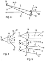
- FIG. 3 schematically shows a transmitted light beam path in a side view, in contrast to Fig. 1 not only a along the optical axis O of the optical transmitting system 16 extending central transmitted light beam 30 of the transmitted light beam 18 is shown, but also the two outer transmitted light beams 32, in the perspective of Fig. 3 one behind the other and so far in the illustration are not visible separately.
- the outer transmitted light beams 32 strike the scanning plane 26 at passage points 38, while the central transmitted light beam 30 is at the point of impact 46 hits the scanning plane 26.
- the calculation of the transmitting optical system 16 can be carried out, for example, on the basis of a reference light line 36 which is produced as an image or projection of the transmitted light bundle 18 after passing through the scanning plane 26 assumed here to be transparent on a reference scanning plane 34 perpendicular to the central transmitted light beam 30 or to the optical Axis O runs.
- a reference light line 36 which is produced as an image or projection of the transmitted light bundle 18 after passing through the scanning plane 26 assumed here to be transparent on a reference scanning plane 34 perpendicular to the central transmitted light beam 30 or to the optical Axis O runs.
- the resulting reference light line 36 is rotated in the plane of the drawing.
- the reference light line 36 has a hyperbolic or parabolic-like profile, the vertex lying in the point of impingement 46.
- the transmitting optics 16 is here exemplified as a biconical lens, wherein the one refractive surface of the lens plan and the other refractive surface in plan view according to Fig. 2 and 4 concave and in side view according to Fig. 1 and 5 is convexly curved.
- the concave curvature of the refractive surface causes according to Fig. 4 the fan-shaped spreading of the transmitted light beam 18, while the convex curvature component according to Fig. 5 the collimation of the transmitted light beam in the triangulation direction T and the angle-dependent change of the radiation angle causes.
- Fig. 4 three spaced apart cutting planes A to C are located.
- the cutting plane A runs in the middle of the transmitting optics 16, the cutting plane C in an outer region and the cutting plane B between the cutting planes A and C.
- the associated sectional views are in Fig. 5 shown.
- a largely parallel collimation of the transmitted light beam 18 takes place. While the beam 18 in the sectional plane A is parallel to the optical axis O, the inclination of the beam 18 with respect to the optical axis O increases toward the outside.
- the effective refractive surface of the transmitting optics 16 may preferably be designed as a free-form surface, the calculation of which is based on the reference light line 36 (FIG. Fig. 3 ).
- the various optical functions of the transmitting optics 16 need not be realized in a single refractive surface, but may be distributed to different refractive surfaces of a single or multiple lenses.
- the receiving optics 24 can be configured in a corresponding manner, wherein essentially the angle-dependent distortions which cause the curvature of the scanning light line 28 to be "undone" again.
- One of the divergent component of the optical transmitting system 16 corresponding property, as provided in the transmitting optics 16 for the fan-shaped spreading of the beam, can be omitted in the receiving optical system 24 in the rule.
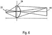
- FIG Fig. 6 An exemplary receiving optical system 24 is shown in FIG Fig. 6 shown schematically.
- the receiving optics 24 are designed such that an imaging region 44 corresponding to the extent of the scanning light line 28 is imaged on the light receiver 22 in the best possible format-filling manner becomes. This avoids that unwanted scattered light reaches the light receiver 22. Accordingly, the passage points 38 of the external transmitted light beams 32 (FIG. Fig. 2 and 3 ) can be imaged in regions of the light receiver 22 that are as close to the edge as possible.
- One or more refractive surfaces of the transmitting optics 16 may also be configured as free-form surfaces,
Landscapes
- Engineering & Computer Science (AREA)
- Physics & Mathematics (AREA)
- General Physics & Mathematics (AREA)
- Radar, Positioning & Navigation (AREA)
- Remote Sensing (AREA)
- Computer Networks & Wireless Communication (AREA)
- Electromagnetism (AREA)
- Aviation & Aerospace Engineering (AREA)
- Automation & Control Theory (AREA)
- Length Measuring Devices By Optical Means (AREA)
- Measurement Of Optical Distance (AREA)
Claims (10)
- Capteur de surveillance (12) pour la détection à résolution spatiale d'objets dans une zone à surveiller (20) selon le principe de triangulation, comportant- un émetteur de lumière pour émettre une lumière d'émission (18) jusque dans la zone à surveiller (20), l'émetteur de lumière comprenant uns source de lumière (14) et une optique d'émission (16) qui présente un axe optique (O),- un récepteur de lumière (22) qui comprend plusieurs éléments récepteurs pour recevoir la lumière en provenance de la zone à surveiller (20), qui est réémise par un objet à détecter (40), et- une optique de réception (24) agencée en amont du récepteur de lumière (22),l'émetteur de lumière, le récepteur de lumière (22) et l'optique de réception (24) étant agencés les uns par rapport aux autres de telle sorte que la position d'une tache de lumière (32) générée à partir de la lumière réémise (26) sur le récepteur de lumière (14) au moyen de l'optique de réception (24) dans une direction de triangulation (T) résulte en fonction de la distance de l'objet (40),
caractérisé en ce que
l'optique d'émission (16) est conçue pour focaliser la lumière émise par la source de lumière (14) pour donner un faisceau lumineux d'émission (18) qui, lors de l'impact sur un plan de balayage (26) s'étendant de façon inclinée par rapport à l'axe optique (O) de l'optique d'émission (16) d'un angle d'inclinaison donnée (β) dans la direction de triangulation (T), génère une ligne de lumière de balayage (28) qui, vue depuis la direction du capteur de surveillance (12), s'étend de façon incurvée concave. - Capteur de surveillance selon la revendication 1,
caractérisé en ce que
l'allure de la ligne de lumière de balayage (28) sur le plan de balayage (26) correspond à un segment d'un cercle, d'une parabole, d'une hyperbole ou d'une ellipse. - Capteur de surveillance selon l'une des revendications précédentes, caractérisé en ce que
en projection sur un plan de balayage de référence (34) s'étendant perpendiculairement à l'axe optique (O) de l'optique d'émission (16), le faisceau lumineux d'émission (18) focalisé par l'optique d'émission (16) génère une ligne de lumière de référence (36) incurvée. - Capteur de surveillance (12) selon l'une des revendications précédentes, caractérisé en ce que
le profil d'intensité de la ligne de lumière de balayage (28) en direction longitudinale et/ou en direction transversale de la ligne de lumière de balayage (28) est homogène. - Capteur de surveillance (12) selon l'une des revendications précédentes, caractérisé en ce que
l'optique de réception (24) est conçue pour générer une image de la ligne de lumière de balayage (28), ladite image correspondant à une ligne droite, sur le récepteur de lumière (22). - Capteur de surveillance (12) selon la revendication 5,
caractérisé en ce que
les éléments récepteurs du récepteur de lumière (22) sont agencés en rangées et en colonnes, et
l'image de la ligne de lumière de balayage (28) sur le récepteur de lumière (22) s'étend parallèlement aux rangées ou aux colonnes. - Capteur de surveillance (12) selon l'une des revendications précédentes, caractérisé en ce que
l'optique d'émission (16) et/ou l'optique de réception (24) comprennent chacune au moins une lentille, au moins une surface réfractive de la lentille étant réalisée sous forme de surface de forme libre. - Capteur de surveillance (12) selon la revendication 7,
caractérisé en ce que
l'optique d'émission (16) présente au moins deux surfaces de forme libre, une première surface de forme libre étant réalisée de telle sorte que celle-ci, prise à elle-seule, générerait une ligne de lumière de balayage (28) droite sur le plan de balayage (26), et la seconde surface de forme libre étant réalisée de telle sorte que celle-ci provoque la courbure de la ligne de lumière de balayage (28). - Véhicule (10) guidé au sol, en particulier véhicule de transport sans conducteur, comportant un capteur de surveillance (12) selon l'une des revendications précédentes pour surveiller un trajet de déplacement (26) du véhicule (10).
- Véhicule (10) selon la revendication 9,
caractérisé en ce que
le capteur de surveillance (12) est agencé sur le véhicule (10) à distance du trajet de déplacement à surveiller (26) et est orienté de telle sorte que l'axe optique (O) de l'optique d'émission (16) coupe un trajet de déplacement plan (26) à une distance donnée du véhicule (10).
Priority Applications (2)
| Application Number | Priority Date | Filing Date | Title |
|---|---|---|---|
| EP17150936.7A EP3349042B1 (fr) | 2017-01-11 | 2017-01-11 | Capteur de surveillance et véhicule relié par le plancher |
| US15/866,835 US10634773B2 (en) | 2017-01-11 | 2018-01-10 | Monitoring sensor and floor-bound vehicle |
Applications Claiming Priority (1)
| Application Number | Priority Date | Filing Date | Title |
|---|---|---|---|
| EP17150936.7A EP3349042B1 (fr) | 2017-01-11 | 2017-01-11 | Capteur de surveillance et véhicule relié par le plancher |
Publications (2)
| Publication Number | Publication Date |
|---|---|
| EP3349042A1 EP3349042A1 (fr) | 2018-07-18 |
| EP3349042B1 true EP3349042B1 (fr) | 2019-05-08 |
Family
ID=57777541
Family Applications (1)
| Application Number | Title | Priority Date | Filing Date |
|---|---|---|---|
| EP17150936.7A Active EP3349042B1 (fr) | 2017-01-11 | 2017-01-11 | Capteur de surveillance et véhicule relié par le plancher |
Country Status (2)
| Country | Link |
|---|---|
| US (1) | US10634773B2 (fr) |
| EP (1) | EP3349042B1 (fr) |
Families Citing this family (2)
| Publication number | Priority date | Publication date | Assignee | Title |
|---|---|---|---|---|
| EP3349042B1 (fr) * | 2017-01-11 | 2019-05-08 | Sick Ag | Capteur de surveillance et véhicule relié par le plancher |
| CN112415494B (zh) * | 2020-12-11 | 2021-08-13 | 福勤智能科技(昆山)有限公司 | Agv双激光雷达位置标定方法、装置、设备和存储介质 |
Family Cites Families (22)
| Publication number | Priority date | Publication date | Assignee | Title |
|---|---|---|---|---|
| US6204916B1 (en) * | 1998-02-03 | 2001-03-20 | Minolta Co., Ltd. | Three dimensional information measurement method and apparatus |
| JP2001004746A (ja) * | 1999-06-16 | 2001-01-12 | Nec Corp | レール走行車両の衝突防止装置 |
| JP3875813B2 (ja) * | 1999-08-30 | 2007-01-31 | 株式会社リコー | 複数ビーム走査装置及び画像形成装置 |
| DE102004047022A1 (de) * | 2004-09-28 | 2006-04-06 | Siemens Ag | Vorrichtung zur Überwachung von Raumbereichen |
| DE102007003024A1 (de) * | 2007-01-20 | 2008-07-31 | Sick Ag | Triangulationssensor mit Entfernungsbestimmung aus Lichtfleckposition und -form |
| ATE545045T1 (de) * | 2009-12-17 | 2012-02-15 | Sick Ag | Optoelektronischer sensor |
| JP5321915B2 (ja) * | 2010-02-18 | 2013-10-23 | 株式会社リコー | 光源装置、光走査装置及び画像形成装置 |
| DE102011000863A1 (de) * | 2011-02-22 | 2012-08-23 | Sick Ag | Optoelektronischer Sensor und Verfahren zur Erfassung von Objekten |
| US20120218564A1 (en) * | 2011-02-24 | 2012-08-30 | Sick Ag | Method for the secure detection and position determination of objects and safety apparatus |
| JP5729358B2 (ja) * | 2011-09-22 | 2015-06-03 | 株式会社リコー | 光ビームスキャナ及びレーザレーダユニット |
| EP2722684B1 (fr) * | 2012-10-19 | 2019-08-28 | Sick Ag | Lecteur laser |
| EP2722687B1 (fr) * | 2012-10-22 | 2015-04-29 | Sick Ag | Dispositif de sécurité pour un véhicule |
| EP2746808B1 (fr) * | 2012-12-18 | 2015-02-25 | Sick Ag | Capteur optoélectronique destiné à la détection d'objets |
| JP6292534B2 (ja) * | 2014-01-23 | 2018-03-14 | 株式会社リコー | 物体検出装置及びセンシング装置 |
| DE102014101312B3 (de) * | 2014-02-04 | 2014-12-04 | Sick Ag | Optoelektronischer Sensor und Verfahren zur Erfassung von Objekten in einem Überwachungsbereich |
| DE102014115260B3 (de) * | 2014-10-20 | 2015-11-12 | Sick Ag | Sicherheitssystem zur Absicherung der Umgebung eines Objekts |
| JP6587385B2 (ja) * | 2014-11-27 | 2019-10-09 | キヤノン株式会社 | 被検体情報取得装置および被検体情報取得方法 |
| DE102015121840A1 (de) * | 2015-12-15 | 2017-06-22 | Sick Ag | Optoelektronischer Sensor und Verfahren zur Erfassung eines Objekts |
| JP6637331B2 (ja) * | 2016-02-22 | 2020-01-29 | 株式会社キーエンス | 安全スキャナ及び光学安全システム |
| JP6851137B2 (ja) * | 2016-02-22 | 2021-03-31 | 株式会社キーエンス | 安全スキャナ |
| EP3220164B1 (fr) * | 2016-03-14 | 2018-03-07 | Sick Ag | Procédé de fonctionnement d'un capteur écartométrique de surveillance et capteur écartométrique de surveillance |
| EP3349042B1 (fr) * | 2017-01-11 | 2019-05-08 | Sick Ag | Capteur de surveillance et véhicule relié par le plancher |
-
2017
- 2017-01-11 EP EP17150936.7A patent/EP3349042B1/fr active Active
-
2018
- 2018-01-10 US US15/866,835 patent/US10634773B2/en active Active
Non-Patent Citations (1)
| Title |
|---|
| None * |
Also Published As
| Publication number | Publication date |
|---|---|
| US20180196128A1 (en) | 2018-07-12 |
| US10634773B2 (en) | 2020-04-28 |
| EP3349042A1 (fr) | 2018-07-18 |
Similar Documents
| Publication | Publication Date | Title |
|---|---|---|
| EP3350615B1 (fr) | Capteur lidar | |
| EP2936193B1 (fr) | Système optique de détection d'objets à mems et véhicule à moteur équipé d'un tel système de détection | |
| EP3474033B1 (fr) | Module d'émission et de réception pour un capteur optoélectronique et procédé de détection d'objets | |
| EP1355128B1 (fr) | Alignement automatique d'un senseur | |
| EP2629050B1 (fr) | Capteur de triangulation | |
| WO2017042097A1 (fr) | Dispositif de balayage laser pour véhicules automobiles | |
| DE102006013292A1 (de) | Vorrichtung zur optischen Distanzmessung | |
| DE102013012789A1 (de) | Abtastende optoelektronische Detektionseinrichtung und Kraftfahrzeug mit einer solchen Detektionseinrichtung | |
| DE10341548A1 (de) | Optoelektronische Erfassungseinrichtung | |
| EP3168642A1 (fr) | Capteur optoélectronique et procédé de détection d'un objet | |
| DE10146639A1 (de) | Lichtgitter mit Strahlteiler | |
| CH695633A5 (de) | Laserentfernungsmessgerät für den Nah- und Fernbereich mit speziellem Empfänger. | |
| EP3349042B1 (fr) | Capteur de surveillance et véhicule relié par le plancher | |
| DE102019207867A1 (de) | Optische Anordnung mit einem verbesserten Aberrationsverhalten und LIDAR-Vorrichtung mit einer derartigen Anordnung | |
| DE102010003544A1 (de) | 3D-TOF-Kamera | |
| DE202017100095U1 (de) | Überwachungssensor und flurgebundenes Fahrzeug | |
| DE102018216201A1 (de) | Optische Anordnung und LIDAR-Vorrichtung mit einer derartigen Anordnung | |
| WO2019072633A1 (fr) | Dispositif optique pour un dispositif de mesure de distance selon le principe lidar | |
| EP3553564B1 (fr) | Capteur mesurant la distance | |
| DE102017129100B4 (de) | Optoelektronischer Sensor und Verfahren zur Erfassung eines Überwachungsbereichs | |
| EP2690398A1 (fr) | Dispositif de détermination de la position d'éléments mécaniques | |
| DE102005007945A1 (de) | Optische Linse | |
| WO2020207740A1 (fr) | Capteur lidar pour l'enregistrement optique d'un champ de vision et procédé pour la commande du capteur lidar | |
| WO2020151898A1 (fr) | Système optique, en particulier système lidar, ainsi que véhicule | |
| EP4293395B1 (fr) | Ensemble émetteur de lumière et ensemble capteur optoélectronique |
Legal Events
| Date | Code | Title | Description |
|---|---|---|---|
| PUAI | Public reference made under article 153(3) epc to a published international application that has entered the european phase |
Free format text: ORIGINAL CODE: 0009012 |
|
| STAA | Information on the status of an ep patent application or granted ep patent |
Free format text: STATUS: REQUEST FOR EXAMINATION WAS MADE |
|
| 17P | Request for examination filed |
Effective date: 20171115 |
|
| AK | Designated contracting states |
Kind code of ref document: A1 Designated state(s): AL AT BE BG CH CY CZ DE DK EE ES FI FR GB GR HR HU IE IS IT LI LT LU LV MC MK MT NL NO PL PT RO RS SE SI SK SM TR |
|
| AX | Request for extension of the european patent |
Extension state: BA ME |
|
| GRAP | Despatch of communication of intention to grant a patent |
Free format text: ORIGINAL CODE: EPIDOSNIGR1 |
|
| STAA | Information on the status of an ep patent application or granted ep patent |
Free format text: STATUS: GRANT OF PATENT IS INTENDED |
|
| RIC1 | Information provided on ipc code assigned before grant |
Ipc: G01S 17/02 20060101ALI20181026BHEP Ipc: G01S 17/48 20060101AFI20181026BHEP Ipc: G01S 17/93 20060101ALI20181026BHEP |
|
| INTG | Intention to grant announced |
Effective date: 20181128 |
|
| GRAS | Grant fee paid |
Free format text: ORIGINAL CODE: EPIDOSNIGR3 |
|
| GRAA | (expected) grant |
Free format text: ORIGINAL CODE: 0009210 |
|
| STAA | Information on the status of an ep patent application or granted ep patent |
Free format text: STATUS: THE PATENT HAS BEEN GRANTED |
|
| AK | Designated contracting states |
Kind code of ref document: B1 Designated state(s): AL AT BE BG CH CY CZ DE DK EE ES FI FR GB GR HR HU IE IS IT LI LT LU LV MC MK MT NL NO PL PT RO RS SE SI SK SM TR |
|
| REG | Reference to a national code |
Ref country code: GB Ref legal event code: FG4D Free format text: NOT ENGLISH |
|
| REG | Reference to a national code |
Ref country code: CH Ref legal event code: EP Ref country code: AT Ref legal event code: REF Ref document number: 1131044 Country of ref document: AT Kind code of ref document: T Effective date: 20190515 |
|
| REG | Reference to a national code |
Ref country code: DE Ref legal event code: R096 Ref document number: 502017001233 Country of ref document: DE |
|
| REG | Reference to a national code |
Ref country code: IE Ref legal event code: FG4D Free format text: LANGUAGE OF EP DOCUMENT: GERMAN |
|
| REG | Reference to a national code |
Ref country code: NL Ref legal event code: MP Effective date: 20190508 |
|
| REG | Reference to a national code |
Ref country code: LT Ref legal event code: MG4D |
|
| PG25 | Lapsed in a contracting state [announced via postgrant information from national office to epo] |
Ref country code: FI Free format text: LAPSE BECAUSE OF FAILURE TO SUBMIT A TRANSLATION OF THE DESCRIPTION OR TO PAY THE FEE WITHIN THE PRESCRIBED TIME-LIMIT Effective date: 20190508 Ref country code: NO Free format text: LAPSE BECAUSE OF FAILURE TO SUBMIT A TRANSLATION OF THE DESCRIPTION OR TO PAY THE FEE WITHIN THE PRESCRIBED TIME-LIMIT Effective date: 20190808 Ref country code: AL Free format text: LAPSE BECAUSE OF FAILURE TO SUBMIT A TRANSLATION OF THE DESCRIPTION OR TO PAY THE FEE WITHIN THE PRESCRIBED TIME-LIMIT Effective date: 20190508 Ref country code: PT Free format text: LAPSE BECAUSE OF FAILURE TO SUBMIT A TRANSLATION OF THE DESCRIPTION OR TO PAY THE FEE WITHIN THE PRESCRIBED TIME-LIMIT Effective date: 20190908 Ref country code: SE Free format text: LAPSE BECAUSE OF FAILURE TO SUBMIT A TRANSLATION OF THE DESCRIPTION OR TO PAY THE FEE WITHIN THE PRESCRIBED TIME-LIMIT Effective date: 20190508 Ref country code: ES Free format text: LAPSE BECAUSE OF FAILURE TO SUBMIT A TRANSLATION OF THE DESCRIPTION OR TO PAY THE FEE WITHIN THE PRESCRIBED TIME-LIMIT Effective date: 20190508 Ref country code: HR Free format text: LAPSE BECAUSE OF FAILURE TO SUBMIT A TRANSLATION OF THE DESCRIPTION OR TO PAY THE FEE WITHIN THE PRESCRIBED TIME-LIMIT Effective date: 20190508 Ref country code: LT Free format text: LAPSE BECAUSE OF FAILURE TO SUBMIT A TRANSLATION OF THE DESCRIPTION OR TO PAY THE FEE WITHIN THE PRESCRIBED TIME-LIMIT Effective date: 20190508 Ref country code: NL Free format text: LAPSE BECAUSE OF FAILURE TO SUBMIT A TRANSLATION OF THE DESCRIPTION OR TO PAY THE FEE WITHIN THE PRESCRIBED TIME-LIMIT Effective date: 20190508 |
|
| PG25 | Lapsed in a contracting state [announced via postgrant information from national office to epo] |
Ref country code: BG Free format text: LAPSE BECAUSE OF FAILURE TO SUBMIT A TRANSLATION OF THE DESCRIPTION OR TO PAY THE FEE WITHIN THE PRESCRIBED TIME-LIMIT Effective date: 20190808 Ref country code: RS Free format text: LAPSE BECAUSE OF FAILURE TO SUBMIT A TRANSLATION OF THE DESCRIPTION OR TO PAY THE FEE WITHIN THE PRESCRIBED TIME-LIMIT Effective date: 20190508 Ref country code: LV Free format text: LAPSE BECAUSE OF FAILURE TO SUBMIT A TRANSLATION OF THE DESCRIPTION OR TO PAY THE FEE WITHIN THE PRESCRIBED TIME-LIMIT Effective date: 20190508 Ref country code: GR Free format text: LAPSE BECAUSE OF FAILURE TO SUBMIT A TRANSLATION OF THE DESCRIPTION OR TO PAY THE FEE WITHIN THE PRESCRIBED TIME-LIMIT Effective date: 20190809 |
|
| PG25 | Lapsed in a contracting state [announced via postgrant information from national office to epo] |
Ref country code: RO Free format text: LAPSE BECAUSE OF FAILURE TO SUBMIT A TRANSLATION OF THE DESCRIPTION OR TO PAY THE FEE WITHIN THE PRESCRIBED TIME-LIMIT Effective date: 20190508 Ref country code: CZ Free format text: LAPSE BECAUSE OF FAILURE TO SUBMIT A TRANSLATION OF THE DESCRIPTION OR TO PAY THE FEE WITHIN THE PRESCRIBED TIME-LIMIT Effective date: 20190508 Ref country code: SK Free format text: LAPSE BECAUSE OF FAILURE TO SUBMIT A TRANSLATION OF THE DESCRIPTION OR TO PAY THE FEE WITHIN THE PRESCRIBED TIME-LIMIT Effective date: 20190508 Ref country code: EE Free format text: LAPSE BECAUSE OF FAILURE TO SUBMIT A TRANSLATION OF THE DESCRIPTION OR TO PAY THE FEE WITHIN THE PRESCRIBED TIME-LIMIT Effective date: 20190508 Ref country code: DK Free format text: LAPSE BECAUSE OF FAILURE TO SUBMIT A TRANSLATION OF THE DESCRIPTION OR TO PAY THE FEE WITHIN THE PRESCRIBED TIME-LIMIT Effective date: 20190508 |
|
| REG | Reference to a national code |
Ref country code: DE Ref legal event code: R097 Ref document number: 502017001233 Country of ref document: DE |
|
| RAP2 | Party data changed (patent owner data changed or rights of a patent transferred) |
Owner name: SICK AG |
|
| PG25 | Lapsed in a contracting state [announced via postgrant information from national office to epo] |
Ref country code: IT Free format text: LAPSE BECAUSE OF FAILURE TO SUBMIT A TRANSLATION OF THE DESCRIPTION OR TO PAY THE FEE WITHIN THE PRESCRIBED TIME-LIMIT Effective date: 20190508 Ref country code: SM Free format text: LAPSE BECAUSE OF FAILURE TO SUBMIT A TRANSLATION OF THE DESCRIPTION OR TO PAY THE FEE WITHIN THE PRESCRIBED TIME-LIMIT Effective date: 20190508 |
|
| PLBE | No opposition filed within time limit |
Free format text: ORIGINAL CODE: 0009261 |
|
| STAA | Information on the status of an ep patent application or granted ep patent |
Free format text: STATUS: NO OPPOSITION FILED WITHIN TIME LIMIT |
|
| PG25 | Lapsed in a contracting state [announced via postgrant information from national office to epo] |
Ref country code: TR Free format text: LAPSE BECAUSE OF FAILURE TO SUBMIT A TRANSLATION OF THE DESCRIPTION OR TO PAY THE FEE WITHIN THE PRESCRIBED TIME-LIMIT Effective date: 20190508 |
|
| 26N | No opposition filed |
Effective date: 20200211 |
|
| PG25 | Lapsed in a contracting state [announced via postgrant information from national office to epo] |
Ref country code: PL Free format text: LAPSE BECAUSE OF FAILURE TO SUBMIT A TRANSLATION OF THE DESCRIPTION OR TO PAY THE FEE WITHIN THE PRESCRIBED TIME-LIMIT Effective date: 20190508 |
|
| PG25 | Lapsed in a contracting state [announced via postgrant information from national office to epo] |
Ref country code: MC Free format text: LAPSE BECAUSE OF FAILURE TO SUBMIT A TRANSLATION OF THE DESCRIPTION OR TO PAY THE FEE WITHIN THE PRESCRIBED TIME-LIMIT Effective date: 20190508 |
|
| REG | Reference to a national code |
Ref country code: CH Ref legal event code: PL |
|
| REG | Reference to a national code |
Ref country code: BE Ref legal event code: MM Effective date: 20200131 |
|
| PG25 | Lapsed in a contracting state [announced via postgrant information from national office to epo] |
Ref country code: LU Free format text: LAPSE BECAUSE OF NON-PAYMENT OF DUE FEES Effective date: 20200111 |
|
| PG25 | Lapsed in a contracting state [announced via postgrant information from national office to epo] |
Ref country code: BE Free format text: LAPSE BECAUSE OF NON-PAYMENT OF DUE FEES Effective date: 20200131 Ref country code: CH Free format text: LAPSE BECAUSE OF NON-PAYMENT OF DUE FEES Effective date: 20200131 Ref country code: LI Free format text: LAPSE BECAUSE OF NON-PAYMENT OF DUE FEES Effective date: 20200131 |
|
| PG25 | Lapsed in a contracting state [announced via postgrant information from national office to epo] |
Ref country code: IE Free format text: LAPSE BECAUSE OF NON-PAYMENT OF DUE FEES Effective date: 20200111 |
|
| PG25 | Lapsed in a contracting state [announced via postgrant information from national office to epo] |
Ref country code: MT Free format text: LAPSE BECAUSE OF FAILURE TO SUBMIT A TRANSLATION OF THE DESCRIPTION OR TO PAY THE FEE WITHIN THE PRESCRIBED TIME-LIMIT Effective date: 20190508 Ref country code: CY Free format text: LAPSE BECAUSE OF FAILURE TO SUBMIT A TRANSLATION OF THE DESCRIPTION OR TO PAY THE FEE WITHIN THE PRESCRIBED TIME-LIMIT Effective date: 20190508 |
|
| PG25 | Lapsed in a contracting state [announced via postgrant information from national office to epo] |
Ref country code: MK Free format text: LAPSE BECAUSE OF FAILURE TO SUBMIT A TRANSLATION OF THE DESCRIPTION OR TO PAY THE FEE WITHIN THE PRESCRIBED TIME-LIMIT Effective date: 20190508 Ref country code: IS Free format text: LAPSE BECAUSE OF FAILURE TO SUBMIT A TRANSLATION OF THE DESCRIPTION OR TO PAY THE FEE WITHIN THE PRESCRIBED TIME-LIMIT Effective date: 20190908 |
|
| REG | Reference to a national code |
Ref country code: AT Ref legal event code: MM01 Ref document number: 1131044 Country of ref document: AT Kind code of ref document: T Effective date: 20220111 |
|
| PG25 | Lapsed in a contracting state [announced via postgrant information from national office to epo] |
Ref country code: AT Free format text: LAPSE BECAUSE OF NON-PAYMENT OF DUE FEES Effective date: 20220111 |
|
| PG25 | Lapsed in a contracting state [announced via postgrant information from national office to epo] |
Ref country code: SI Free format text: LAPSE BECAUSE OF FAILURE TO SUBMIT A TRANSLATION OF THE DESCRIPTION OR TO PAY THE FEE WITHIN THE PRESCRIBED TIME-LIMIT Effective date: 20190508 |
|
| PGFP | Annual fee paid to national office [announced via postgrant information from national office to epo] |
Ref country code: GB Payment date: 20260122 Year of fee payment: 10 |
|
| PGFP | Annual fee paid to national office [announced via postgrant information from national office to epo] |
Ref country code: DE Payment date: 20260120 Year of fee payment: 10 |
|
| PGFP | Annual fee paid to national office [announced via postgrant information from national office to epo] |
Ref country code: FR Payment date: 20260127 Year of fee payment: 10 |