EP3349299A1 - Kabel zur übertragung elektromagnetischer wellen - Google Patents
Kabel zur übertragung elektromagnetischer wellen Download PDFInfo
- Publication number
- EP3349299A1 EP3349299A1 EP18151170.0A EP18151170A EP3349299A1 EP 3349299 A1 EP3349299 A1 EP 3349299A1 EP 18151170 A EP18151170 A EP 18151170A EP 3349299 A1 EP3349299 A1 EP 3349299A1
- Authority
- EP
- European Patent Office
- Prior art keywords
- cable
- core
- sleeve
- support
- cable according
- Prior art date
- Legal status (The legal status is an assumption and is not a legal conclusion. Google has not performed a legal analysis and makes no representation as to the accuracy of the status listed.)
- Withdrawn
Links
- 230000005684 electric field Effects 0.000 claims description 33
- 229910052751 metal Inorganic materials 0.000 claims description 19
- 239000002184 metal Substances 0.000 claims description 19
- 239000003989 dielectric material Substances 0.000 claims description 16
- 239000000463 material Substances 0.000 claims description 13
- -1 polyethylene Polymers 0.000 claims description 8
- 230000000644 propagated effect Effects 0.000 claims description 7
- 239000004698 Polyethylene Substances 0.000 claims description 4
- 239000004743 Polypropylene Substances 0.000 claims description 4
- 229910044991 metal oxide Inorganic materials 0.000 claims description 4
- 150000004706 metal oxides Chemical class 0.000 claims description 4
- 229920000573 polyethylene Polymers 0.000 claims description 4
- 229920001155 polypropylene Polymers 0.000 claims description 4
- YCKRFDGAMUMZLT-UHFFFAOYSA-N Fluorine atom Chemical compound [F] YCKRFDGAMUMZLT-UHFFFAOYSA-N 0.000 claims description 3
- 150000001336 alkenes Chemical class 0.000 claims description 3
- 239000011737 fluorine Substances 0.000 claims description 3
- 229910052731 fluorine Inorganic materials 0.000 claims description 3
- JRZJOMJEPLMPRA-UHFFFAOYSA-N olefin Natural products CCCCCCCC=C JRZJOMJEPLMPRA-UHFFFAOYSA-N 0.000 claims description 3
- 230000005540 biological transmission Effects 0.000 description 14
- 238000009826 distribution Methods 0.000 description 10
- 238000005253 cladding Methods 0.000 description 8
- 230000000694 effects Effects 0.000 description 7
- 229910052782 aluminium Inorganic materials 0.000 description 5
- XAGFODPZIPBFFR-UHFFFAOYSA-N aluminium Chemical compound [Al] XAGFODPZIPBFFR-UHFFFAOYSA-N 0.000 description 5
- 239000004020 conductor Substances 0.000 description 5
- 229920000089 Cyclic olefin copolymer Polymers 0.000 description 4
- 230000005672 electromagnetic field Effects 0.000 description 4
- 230000005855 radiation Effects 0.000 description 4
- 230000001902 propagating effect Effects 0.000 description 3
- 238000005452 bending Methods 0.000 description 2
- 239000002131 composite material Substances 0.000 description 2
- 239000004033 plastic Substances 0.000 description 2
- 229920003023 plastic Polymers 0.000 description 2
- 230000010287 polarization Effects 0.000 description 2
- RYGMFSIKBFXOCR-UHFFFAOYSA-N Copper Chemical compound [Cu] RYGMFSIKBFXOCR-UHFFFAOYSA-N 0.000 description 1
- PNEYBMLMFCGWSK-UHFFFAOYSA-N aluminium oxide Inorganic materials [O-2].[O-2].[O-2].[Al+3].[Al+3] PNEYBMLMFCGWSK-UHFFFAOYSA-N 0.000 description 1
- 230000000052 comparative effect Effects 0.000 description 1
- 239000012141 concentrate Substances 0.000 description 1
- 229910052802 copper Inorganic materials 0.000 description 1
- 239000010949 copper Substances 0.000 description 1
- 229910052593 corundum Inorganic materials 0.000 description 1
- 238000001125 extrusion Methods 0.000 description 1
- 230000002349 favourable effect Effects 0.000 description 1
- 239000012530 fluid Substances 0.000 description 1
- PCHJSUWPFVWCPO-UHFFFAOYSA-N gold Chemical compound [Au] PCHJSUWPFVWCPO-UHFFFAOYSA-N 0.000 description 1
- 229910052737 gold Inorganic materials 0.000 description 1
- 239000010931 gold Substances 0.000 description 1
- 230000005484 gravity Effects 0.000 description 1
- 238000004519 manufacturing process Methods 0.000 description 1
- 239000000203 mixture Substances 0.000 description 1
- 238000012986 modification Methods 0.000 description 1
- 230000004048 modification Effects 0.000 description 1
- 230000002093 peripheral effect Effects 0.000 description 1
- 238000007747 plating Methods 0.000 description 1
- 239000004810 polytetrafluoroethylene Substances 0.000 description 1
- 229920001343 polytetrafluoroethylene Polymers 0.000 description 1
- 230000002265 prevention Effects 0.000 description 1
- 229910001845 yogo sapphire Inorganic materials 0.000 description 1
Images





Classifications
-
- H—ELECTRICITY
- H01—ELECTRIC ELEMENTS
- H01P—WAVEGUIDES; RESONATORS, LINES, OR OTHER DEVICES OF THE WAVEGUIDE TYPE
- H01P3/00—Waveguides; Transmission lines of the waveguide type
- H01P3/12—Hollow waveguides
- H01P3/123—Hollow waveguides with a complex or stepped cross-section, e.g. ridged or grooved waveguides
-
- H—ELECTRICITY
- H01—ELECTRIC ELEMENTS
- H01P—WAVEGUIDES; RESONATORS, LINES, OR OTHER DEVICES OF THE WAVEGUIDE TYPE
- H01P3/00—Waveguides; Transmission lines of the waveguide type
- H01P3/16—Dielectric waveguides, i.e. without a longitudinal conductor
-
- H—ELECTRICITY
- H01—ELECTRIC ELEMENTS
- H01P—WAVEGUIDES; RESONATORS, LINES, OR OTHER DEVICES OF THE WAVEGUIDE TYPE
- H01P3/00—Waveguides; Transmission lines of the waveguide type
- H01P3/12—Hollow waveguides
- H01P3/122—Dielectric loaded (not air)
Definitions
- the present invention relates to a cable for transmitting electromagnetic waves.
- Japanese Unexamined Patent Publication No. JP08-195605 discloses a coaxial cable and a waveguide for transmitting electromagnetic waves, such as microwaves and millimeter waves.
- Japanese Unexamined Patent Publication No. JP06-034715 discloses not only a coaxial line and a waveguide, as a microwave line, but also a coplanar line.
- the present invention relates to a cable for electromagnetic waves as one embodiment thereof.
- the cable for transmitting electromagnetic waves includes a core extending along a longitudinal direction of the cable, a sleeve extending along the longitudinal direction of the cable while surrounding the core so as to provide a cavity between the core and the sleeve, and a support that supports the core in the cavity in the sleeve.
- Each of the core, the sleeve, and the support includes a dielectric.
- a coaxial cable has a tendency to concentrate an electric field on a surface of a conductor with heightening frequencies of electromagnetic waves to be transmitted. This concentration causes a resistive loss (skin resistance) which locally increases resistance, whereby propagation loss of the electromagnetic waves can be increased.
- One aspect of the present invention provides a cable which can reduce propagation loss of electromagnetic waves.
- a cable for electromagnetic waves is a cable for transmitting electromagnetic waves.
- the cable includes a core extending along the longitudinal direction of the cable, a sleeve extending along the longitudinal direction of the cable while surrounding the core so as to provide a cavity between the core and the sleeve, and a support that supports the core in the cavity in the sleeve.
- Each of the core, the sleeve, and the support includes a dielectric.
- the cable for electromagnetic waves is formed with the core that includes the dielectric. Accordingly, this cable prevents from increasing the resistive loss (skin resistance) that causes by concentrating electric field on a surface of a conductor such as the core to locally increase resistance when electromagnetic waves such as microwaves and millimeter waves are transmitted, whereby this cable can reduce propagation loss of the electromagnetic waves.
- the cable for electromagnetic waves is formed so that a cavity is formed in a region between the core and the sleeve, the region corresponding to a cladding, and thus air or the like with a dielectric loss tangent of zero is positioned in so-called a cladding corresponding region, whereby this cable can further reduce propagation loss of the electromagnetic waves of the entire cable.
- the cable for electromagnetic waves provides the support that supports the core in the cavity, the core is reliably supported in the sleeve, whereby the cable can secure the cavity with a predetermined size. If there is not this kind of support, the core and the sleeve are brought into contact with each other, or are adjacent to each other, to cause a higher mode propagating through the sleeve, thereby increasing loss at a receiving section.
- electromagnetic waves to be transmitted through the cable for electromagnetic waves includes electromagnetic waves at 30 GHz to 300 GHz, such as millimeter waves, or extremely high frequency (EHF), for example, the cable can be used when electromagnetic waves other than the millimeter waves are transmitted.
- the support may be formed integrally with the core, and may be fixed to an inner periphery of the sleeve. In this case, a positional relationship between the core and the sleeve is fixed, and thus transmission characteristics through the cable for electromagnetic waves can be stabilized.
- the support may be formed integrally with the core, and may be provided to be brought into contact with the inner periphery of the sleeve.
- the core and the support integrated with each other, appropriately move in the sleeve to enable transmission characteristics through the cable for electromagnetic waves to be stabilized.
- This structure enables the core and the support to be easily formed with a dielectric material different from that of the sleeve, and thus the sleeve may be formed of a material harder than that of the core and the like to prevent deformation of the sleeve due to pressure from the outside, for example.
- the support with a width less than a width or a diameter in a cross-sectional shape of the core may extend to the inner periphery of the sleeve.
- a wider region for cavity in the sleeve can be secured, and thus a region of air or the like with a dielectric loss tangent of zero, the region corresponding to a cladding, can be widened to further reduce propagation loss.
- the support with a width more than a thickness of the sleeve may extend to the inner periphery of the sleeve. In this case, strength of the support can be secured to prevent breakage or the like of the support when the cable is used.
- the support may be formed to be inclined at an angle of 45 degrees or more with respect to a direction of an electric field propagated through the core.
- the support is formed to be inclined at an angle of 45 degrees or more with respect to the direction of an electric field, radiation of electromagnetic waves due to a bend of the cable can be reduced, and thus bend loss can be reduced.
- a cross-sectional shape of the core may be any one of a square, a rectangle, a circle, an ellipse, a trapezoid, and a polygon.
- the cross-sectional shape of the core may have length in a long axis different from that in a short axis.
- TE polarized waves transverse electric waves
- TM polarized waves transverse magnetic waves
- polarization multiplexed communication is also available.
- a cross-sectional shape of the core may be any one of a square, a rectangle, a trapezoid, and a polygon, and the support may be connected at its base end to a corner of the core.
- the support is disposed in a portion with a relatively low electric field intensity, and thus a leakage of the electric field to the support can be reduced to reduce bend loss.
- the cable for electromagnetic waves may further include a metal layer that covers an outer periphery of the sleeve.
- a metal layer that covers an outer periphery of the sleeve.
- the core, the sleeve, and the support may be formed of the same dielectric material.
- the cable for electromagnetic waves can be integrally and easily manufactured by extrusion molding.
- the dielectric material constituting the core, the sleeve, and the support may contain polyethylene, polypropylene, olefin-based material, or fluorine-based material. In this case, a desired flexibility can be provided in the cable.
- any one of the core, the sleeve, and the support may contain metal oxide that adjusts permittivity or dielectric loss tangent.
- the cable with adjusted permittivity and dielectric loss tangent can be easily formed.
- the core, the sleeve, and the support may be formed integrally with each other. In this case, a positional relationship between the core and the sleeve is fixed, and thus transmission characteristics through the cable for electromagnetic waves can be stabilized.
- the cable for electromagnetic waves may further include an auxiliary support that assists support of the core by using the support, and the auxiliary support may be provided between the support and the sleeve while being in non-contact with the core.
- the auxiliary support may connect and fix the support and the sleeve to each other. This enables the strength of the cable against a bend to be further increased.
- the support may include a pair of beam members, and the pair of beam members may be provided in the sleeve to be parallel or symmetrical to each other.
- the pair of beam members may be provided in the sleeve to be parallel or symmetrical to each other.
- a ratio of the cavity in the sleeve to a total cross-sectional area of an inner periphery of the sleeve, in a cross-sectional view of the cable may be 30% or more. In this case, propagation loss can be reduced. In addition, flexibility of the cable can be increased. Further, in the cable for electromagnetic waves, a ratio of the cavity in the sleeve to the total cross-sectional area of an inner periphery of the sleeve, in a cross-sectional view of the cable, may be 50% or more. In this case, dielectric loss can be further reduced. In addition, the flexibility of the cable can be further increased.
- FIG. 1 is a sectional view taken along a direction perpendicular to an axial direction of a cable for millimeter waves according to a first embodiment of the present invention.
- a cable 10 is a cable for transmitting electromagnetic waves such as millimeter waves, for example, and includes a core 12, a sleeve 14, and a support 16.
- the cable 10 is formed so that cavities P1, P2, P3, and P4 are provided between the core 12 and the sleeve 14.
- Each of the cavities PI to P4 defined by the support 16 is to be filled with air with a dielectric loss tangent of zero, for example.
- the "millimeter waves" to be used here means electromagnetic waves within a frequency band from 30 GHz to 300 GHz.
- the core 12 is a region with a function of mainly transmitting the millimeter waves, and is substantially formed of a dielectric to extend along in a longitudinal direction of the cable 10. While the core 12 is in the cross-sectional shape of a rectangle with a long axis and a short axis different from each other in length in FIG. 1 , the core 12 may be in the shape of any one of a square, a circle, an ellipse, a trapezoid, and a polygon.
- plastic material such as polyethylene, polypropylene, olefin-based material including cycloolefin polymer (COP) or cyclic olefin polymer (COC), and fluorine material of PFA, PTFE, or the like, can be shown by way of example.
- the core 12 may be formed of composite material in which material (metal oxide) such as Al 2 O 3 and BiTiO 2 for adjusting permittivity or dielectric loss tangent is added to the plastic material described above.
- the sleeve 14 and the support 16 described later also can be formed of dielectric material similar to the above or composite material of the dielectric material, similar to the above.
- the sleeve 14 is substantially formed of a dielectric in the shape of a cylinder, and extends along the longitudinal direction of the cable 10 to surround the core 12. As described above, the sleeve 14 is formed so that the cavities PI to P4 each with a predetermined size are provided between the core 12 and the sleeve 14.
- the cavities PI to P4 can be formed so that a total ratio of the cavities PI to P4 in the sleeve 14 to a total cross-sectional area of the inner periphery of the sleeve 14, in a cross-sectional view of the cable 10, is to be 50% or more, and the total ratio of the cavities PI to P4 to the total cross-sectional area of the inner periphery of the sleeve 14 may be 30% or more.
- the support 16 is a member for supporting the core 12 in a region of the cavities PI to P4 in the sleeve 14, and is substantially formed of a dielectric.
- the support 16 includes four plate-shaped beam members 16a, 16b, 16c, and 16d, extending from four respective corners of the core 12 to an inner peripheral surface of the sleeve 14 in a substantially radial manner, in a cross-sectional view.
- the support 16 is formed so that an angle between an electric field direction and each of the beam members 16a to 16d is to be 45 degrees.
- the beam members 16a and 16b, and the beam members 16c and 16d are disposed to be axially symmetrical to each other with respect to a vertical line passing through the center of the core 12.
- the beam members 16a to 16d each can have a width that is less than a width (in the long axis and the short axis) of the core 12 in a cross-sectional shape, or a diameter (in a case where a cross-sectional shape is a circle), and that is more than a thickness of the sleeve 14.
- the beam members 16a to 16d formed as described above connect the core 12 to the sleeve 14 as supports of the core 12. Base ends of the beam members 16a to 16d are fixed to the corresponding corners of the core 12, and leading ends thereof are fixed to an inner periphery of the sleeve 14.
- Each of the beam members 16a to 16d constituting the support 16 may be a plate-like member continuously extending along the longitudinal direction of the cable by a constant length, or a plate-like member that intermittently has an opening whose length is variable.
- the core 12, the sleeve 14, and the support 16, may be integrally formed with the same material, or may be separately formed with different materials to be connected to each other.
- FIG. 2 illustrates an electric field intensity distribution acquired by electromagnetic field distribution calculation, in the cable for millimeter waves illustrated in FIG. 1 .
- a white region in FIG. 2 shows a region with high electric field intensity, and a blacker region has a lower electric field intensity.
- polyethylene was selected as a dielectric material constituting the core 12, the sleeve 14, and the support 16, and then a width of the core 12 in the short axis direction (a vertical direction in FIG. 2 ) was set at 1.3 mm, a width of the core 12 in the long axis direction (a side-to-side direction in FIG.
- an electric field intensity distribution transmission was acquired by electromagnetic field distribution calculation of a basic mode (fundamental mode) in a case where a frequency of electromagnetic waves to be transmitted was 100 GHz.
- the term "basic mode” here is the same as a mode by TE polarized waves in TE polarized waves (Transverse Electric Waves) and TM polarized waves (Transverse Magnetic Waves). As illustrated in FIG.
- the core 12 is formed of a dielectric, and a region between the core 12 and the sleeve 14, corresponding to a cladding, is formed of the cavities PI to P4. Accordingly, when radio waves such as microwaves and millimeter waves are transmitted, not only increase in loss due to locally increased resistance (skin resistance) caused by an electric field concentrated on a surface of a conductor of the core 12 and the like is reduced, but also propagation loss of millimeter waves can be further reduced, because a region corresponding to claddings 103 and 113 is formed to be he cavities PI to P4 to allow air or the like with a dielectric loss tangent of zero to be positioned in a cladding corresponding region.
- the cable 10 for millimeter waves is provided with the support 16 for supporting the core 12, in the region of the cavities PI to P4, and thus the core 12 is to be reliably supported in the sleeve 14 to enable transmission characteristics to be stabilized.
- the cable 10 for millimeter waves according to the present embodiment enables flexibility to be provided in a cable while reducing transmission loss when millimeter waves are transmitted.
- the support 16 is formed integrally with the core 12, and is fixed to the inner periphery of the sleeve 14.
- a positional relationship between the core 12 and the sleeve 14 is fixed, and also the region of the cavities PI to P4 can be stabilized, whereby transmission characteristics through the cable 10 for millimeter waves can be stabilized.
- the support 16 with a width less than a width or a diameter in a cross-sectional shape of the core 12 extends to the inner periphery of the sleeve 14. Accordingly, a wider region for the cavities PI to P4 in the sleeve 14 can be secured, and thus a region of air or the like with a dielectric loss tangent of zero, the region corresponding to a cladding, can be widened to further reduce transmission loss.
- the support 16 with a width more than a thickness of the sleeve 14 extends to the inner periphery of the sleeve 14. Accordingly, breakage or the like of the support 16 can be prevented when the cable 10 is used.
- the support 16 is provided to be inclined at an angle of 45 degrees with respect to a direction of an electric field propagated through the core 12. Accordingly, radiation of electromagnetic waves due to a bend of the cable can be reduced, and thus bend loss can be reduced.
- the support 16 may be provided to be inclined at an angle of 45 degrees or more with respect to the direction of an electric field propagated through the core 12.
- a cross-sectional shape of the core 12 may be any one of a square, a rectangle, a circle, an ellipse, a trapezoid, and a polygon, a shape with length in a long axis and length in a short axis, different from each other, such as a rectangle, an ellipse, and a trapezoid, is preferable.
- TE polarized waves and TM polarized waves of electromagnetic waves to be propagated can be completely separated, and this enables a cross talk between modes by both the polarized waves to be reduced.
- polarization multiplexed communication is also available.
- any one of the core 12, the sleeve 14, and the support 16 can contain metal oxide to adjust permittivity or dielectric loss tangent.
- the cable 10 with adjusted permittivity and dielectric loss tangent can be easily manufactured.
- FIG. 4 is a sectional view taken along a direction perpendicular to an axial direction of the cable for millimeter waves according to the second embodiment of the present invention.
- a cable 10A for millimeter waves illustrated in FIG. 4 includes a core 12, a sleeve 14, and a support 16, as with the cable 10 for millimeter waves of the first embodiment, and further includes a metal layer 18 formed of an aluminum film on an outer periphery of the sleeve 14.
- the metal layer 18 is a layer serving as a reflecting mirror, and has a thickness of 1 ⁇ m or more, for example.
- the metal layer 18 may be formed by wrapping a film-like member around the outer periphery of the sleeve 14, or may be formed by directly applying plating thereto.
- As the metal layer 18, copper, gold, or the like, other than aluminum, may be used.
- the cable 10A for millimeter waves with the structure described above, in addition to the effect of the cable 10 for millimeter waves according to the first embodiment, even when the cable 10A is bent, electromagnetic waves can propagate through the core 12, and thus radiation of transmitting millimeter waves or the like to the outside of the cable 10A can be reduced by the metal layer 18 positioned in the outer periphery of the cable.
- the metal layer 18 positioned in the outer periphery of the cable.
- FIG. 5A illustrates an example of bend loss of the cable for millimeter waves illustrated in FIG. 1 .
- FIG. 5B illustrates an example of bend loss of the cable for millimeter waves illustrated in FIG. 4 .
- FIGS. 5A and 5B each show a state of propagation in a bent portion when the cables 10 and 10A for millimeter waves each are bent in a long axis direction of the core 12 by 90 degrees at a radius of 25mm. While some of millimeter waves propagating through the cable from an incident direction of millimeter waves to an output direction thereof radiated to the outside of the cable (electric field intensity in the cable was reduced in some portions) in FIG. 5A, FIG.
- FIG. 5B shows a state where millimeter waves propagating through the cable from an incident direction of millimeter waves to an output direction thereof did not radiate to the outside of the cable (electric field intensity in the cable was not reduced), and were reflected by the metal layer 18 (an aluminum film) to join into the core 12 again. That is, it was perceived that bend loss was reduced by providing the metal layer 18 such as an aluminum film.
- bend loss in the examples shown in FIGS. 5A and 5B was calculated, a calculation result of bend loss in the example of FIG. 5A was 4.5 dB/bend, in contrast, a calculation result of bend loss in the example of FIG. 5B was reduced to 0.6 dB/bend, and thus it was perceived that propagation characteristics was further improved.
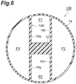
- FIG. 6 is a sectional view taken along a direction perpendicular to an axial direction of the cable for millimeter waves according to the third embodiment of the present invention.
- a cable 10B for millimeter waves illustrated in FIG. 6 includes a core 12, a sleeve 14, and a support 16B, as with the cable 10 for millimeter waves of the first embodiment. While the support 16B has material composition and the like similar to those of the support 16 of the first embodiment, a placement direction of the support 16B is different from that of the support 16 of the first embodiment.
- the support 16B is provided to have an angle of 90 degrees with respect to a direction of an electric field propagated through the core 12.
- beam members 16e and 16f, and beam members 16g and 16h, constituting the support 16B are formed to be parallel to each other.
- FIG. 7A illustrates an example of bend loss of the cable for millimeter waves illustrated in FIG. 1 .
- FIG. 7B illustrates an example of bend loss of the cable for millimeter waves illustrated in FIG. 6 .
- FIGS. 7A and 7B respectively show electric field intensity distributions of the cables 10 and 10B, in portions in each of which a bend was ended when each of the cables 10 and 10B was bent in the long axis direction of the core 12 by 90 degrees at a radius of 25 mm.
- FIG. 7A illustrates an example of bend loss of the cable for millimeter waves illustrated in FIG. 1 .
- FIG. 7B illustrates an example of bend loss of the cable for millimeter waves illustrated in FIG. 6 .
- FIGS. 7A and 7B respectively show electric field intensity distributions of the cables 10 and 10B, in portions in each of which a bend was ended when each of the cables 10 and 10B was bent in the long axis direction of the core 12 by 90 degrees at a radius of 25 mm.
- the beam members of the cable 10B extended in a direction orthogonal to an electric field, and thus even if the cable 10B was bent, a leakage of the electric field was less likely to occur, and then it was perceived that electromagnetic waves were relatively trapped in the core 12 even in a bent portion, and an emission of the electromagnetic waves to the outside of the cable was reduced. That is, it was perceived that a leakage of an electric field to the beam members 16e to 16h in the bent portion was able to be reduced by disposing each of the beam members 16e to 16h of the support 16B to have an angle of 90 degrees with respect to the electric field direction.
- a placement angle of each of the beam members with respect to the electric field direction is 90 degrees or more as described above, an angle of 45 degrees or more enables a leakage of the electric field in a bent portion to be reduced as shown in FIG. 7A .
- bend loss in the examples shown in FIGS. 7A and 7B was calculated, a calculation result of bend loss in the example of FIG. 7A was 4.5 dB/bend, in contrast, a calculation result of bend loss in the example of FIG. 7B was reduced to 2.3 dB/bend.
- a metal layer 18 of an aluminum film similar to that of the second embodiment was provided in an outer periphery of the cable in the example of FIG. 7B , it was perceived that bend loss was further reduced to 0.4 dB/bend.
- the cable 10B according to the present embodiment also can achieve operation effect similar to that of the cable 10 according to the first embodiment.
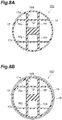
- FIG. 8A is a sectional view taken along a direction perpendicular to an axial direction of the cable for millimeter waves according to the fourth embodiment of the present invention
- FIG. 8B is a sectional view taken along a direction perpendicular to an axial direction of a cable for millimeter waves according to a variation of the fourth embodiment of the present invention.
- the 8A includes a core 12, a sleeve 14, and a support 16B provided with beam members 16e to 16h, as with the cable 10B for millimeter waves of the third embodiment, and further includes an auxiliary support 17.
- the auxiliary support 17 assists support of the core 12 by using the support 16B, and is formed of plate-shaped beam members 17a and 17b that are provided to be orthogonal to the corresponding beam members 16e to 16h constituting the support 16B at an intermediate portion of each of the beam members.
- the beam members 17a and 17b are provided not to be directly in contact with the core 12 formed of a dielectric, and thus can increase strength of the cable 10C against a bend without increasing propagation loss in the cable 10C.
- a kink tilt or tangle
- the cable 10C according to the present embodiment can prevent a kink up to a bend radius of 18 mm.
- a metal layer 18 similar to that of the second embodiment may be provided around an outer periphery of the cable 10C illustrated in FIG. 8A to form a cable 10D illustrated in FIG. 8B . In this case, bend loss can be further reduced.
- the cables 10C and 10D according to the present embodiment also can achieve operation effect similar to that of the cable 10 according to the first embodiment.
- FIG. 9A is a sectional view taken along a direction perpendicular to an axial direction of the cable for millimeter waves according to the fifth embodiment of the present invention
- FIG. 9B is a sectional view taken along a direction perpendicular to an axial direction of a cable for millimeter waves according to a variation of the fifth embodiment of the present invention.
- a cable 10E for millimeter waves illustrated in FIG. 9A includes a core 12, a sleeve 14, and a support 16E, as with the cable 10 for millimeter waves of the first embodiment.
- the core 12 and the support 16E are integrally formed of the same dielectric material, however, the sleeve 14 is not connected to a leading end of each of beam members 16i to 161 of the support 16E, and is separated therefrom to be formed as a separate member.
- the sleeve 14 may be formed of a dielectric material identical to or different from that of the core 12 and the like.
- the support 16E of the cable 10E for millimeter waves has a length that allows the support 16E to slightly fail to reach an inner periphery of the sleeve 14, as illustrated in FIG. 9A , and Cable 10E is formed in the longitudinal direction to have a portion that is to be in contact with the inner periphery of the sleeve due to gravity, together with a portion that is not in contact therewith.
- a core 12 with beams, having a size slightly smaller than an inner diameter of the sleeve 14, is previously formed, and then the core 12 with beams is inserted into the cylindrical sleeve 14 to enable the cable to be manufactured.
- a dielectric material constituting the core 12 with beams may be identical to a dielectric material constituting the sleeve 14, in the cable 10E for millimeter waves, the cable 10E also can have a structure for preventing deformation due to pressure from the outside of the cable by using a dielectric material constituting the sleeve 14 harder than a dielectric material constituting the core 12 with beams.
- a metal layer 18 similar to that of the second embodiment may be provided around an outer periphery of the cable 10E illustrated in FIG. 9A to form a cable 10F illustrated in FIG. 9B . In this case, bend loss can be further reduced.
- the metal layer 18 also can be provided (applied) on an inner periphery side of the sleeve 14 in this case.
- the present invention is not limited to the embodiments described above, and can be applied to various embodiments.
- millimeter waves are described as electromagnetic waves to be transmitted in the embodiments described above, this is because it is desirable to use a frequency with a small imaginary part ⁇ " r of complex permittivity to reduce dielectric loss in a cable, as illustrated in FIG. 10 .
- electromagnetic waves of millimeter waves with a range from 30 GHz to 300 GHz are suitable for transmission
- the cable according to the present embodiment may be obviously used for transmission using electromagnetic waves other than the millimeters wave, if dielectric loss in the cable is within an allowable range.
- a fluid other than air may be injected into the cavities PI to P4, if dielectric loss tangent can be achieved to be zero or close to zero.
Landscapes
- Communication Cables (AREA)
- Waveguides (AREA)
- Insulated Conductors (AREA)
Applications Claiming Priority (1)
| Application Number | Priority Date | Filing Date | Title |
|---|---|---|---|
| US15/403,335 US20180198184A1 (en) | 2017-01-11 | 2017-01-11 | Cable for transmitting electromagnetic waves |
Publications (1)
| Publication Number | Publication Date |
|---|---|
| EP3349299A1 true EP3349299A1 (de) | 2018-07-18 |
Family
ID=60954942
Family Applications (1)
| Application Number | Title | Priority Date | Filing Date |
|---|---|---|---|
| EP18151170.0A Withdrawn EP3349299A1 (de) | 2017-01-11 | 2018-01-11 | Kabel zur übertragung elektromagnetischer wellen |
Country Status (4)
| Country | Link |
|---|---|
| US (1) | US20180198184A1 (de) |
| EP (1) | EP3349299A1 (de) |
| JP (1) | JP2018113666A (de) |
| CN (1) | CN108306086A (de) |
Cited By (1)
| Publication number | Priority date | Publication date | Assignee | Title |
|---|---|---|---|---|
| EP3726642A1 (de) * | 2019-04-18 | 2020-10-21 | Thales | Polarisationsschirm mit breitband-hochfrequenz-polarisationszelle(n) |
Families Citing this family (7)
| Publication number | Priority date | Publication date | Assignee | Title |
|---|---|---|---|---|
| CN106876850A (zh) * | 2015-12-14 | 2017-06-20 | 泰科电子(上海)有限公司 | 介电波导 |
| DE102017116347A1 (de) * | 2017-07-20 | 2019-01-24 | Huber + Suhner Ag | Wellenleitung für elektromagnetische Wellen, Wellenleiterverbinder sowie Kommunikationsverbindung |
| EP3787100B1 (de) * | 2019-08-30 | 2025-04-23 | TE Connectivity Germany GmbH | Ablenkvorrichtung für mm-wellen, verbindungsanordnung |
| USD1094313S1 (en) | 2022-05-20 | 2025-09-23 | Samtec, Inc. | Electrical connector |
| KR102772533B1 (ko) * | 2023-08-31 | 2025-02-27 | 주식회사 유니컨 | 통신 선로 및 통신 시스템 |
| KR102848048B1 (ko) * | 2023-10-04 | 2025-08-20 | 주식회사 유니컨 | 통신 선로 |
| KR102824243B1 (ko) * | 2023-11-06 | 2025-06-24 | 주식회사 유니컨 | 통신 선로 및 이를 이용한 통신 시스템 |
Citations (7)
| Publication number | Priority date | Publication date | Assignee | Title |
|---|---|---|---|---|
| FR1190178A (fr) * | 1958-01-16 | 1959-10-09 | Comp Generale Electricite | Ligne pour la transmission des ondes eh10 |
| US3434774A (en) * | 1965-02-02 | 1969-03-25 | Bell Telephone Labor Inc | Waveguide for millimeter and optical waves |
| FR2380647A1 (fr) * | 1977-02-11 | 1978-09-08 | Patelhold Patentverwertung | Conducteur d'ondes pour la transmission d'energie electromagnetique |
| JPH0634715A (ja) | 1992-07-17 | 1994-02-10 | Mitsubishi Electric Corp | 高周波帯プローブヘッド |
| JPH08195605A (ja) | 1995-01-17 | 1996-07-30 | Nippon Telegr & Teleph Corp <Ntt> | 導波管 |
| GB2385478A (en) * | 2001-12-20 | 2003-08-20 | Liquip Sales Pty Ltd | Probe for liquid level sensor |
| EP2363913A1 (de) * | 2010-03-03 | 2011-09-07 | Astrium Limited | Wellenleiter |
Family Cites Families (2)
| Publication number | Priority date | Publication date | Assignee | Title |
|---|---|---|---|---|
| GB1392452A (en) * | 1971-08-02 | 1975-04-30 | Nat Res Dev | Waveguides |
| CN106876850A (zh) * | 2015-12-14 | 2017-06-20 | 泰科电子(上海)有限公司 | 介电波导 |
-
2017
- 2017-01-11 US US15/403,335 patent/US20180198184A1/en not_active Abandoned
- 2017-08-31 JP JP2017167678A patent/JP2018113666A/ja active Pending
-
2018
- 2018-01-10 CN CN201810022547.XA patent/CN108306086A/zh active Pending
- 2018-01-11 EP EP18151170.0A patent/EP3349299A1/de not_active Withdrawn
Patent Citations (7)
| Publication number | Priority date | Publication date | Assignee | Title |
|---|---|---|---|---|
| FR1190178A (fr) * | 1958-01-16 | 1959-10-09 | Comp Generale Electricite | Ligne pour la transmission des ondes eh10 |
| US3434774A (en) * | 1965-02-02 | 1969-03-25 | Bell Telephone Labor Inc | Waveguide for millimeter and optical waves |
| FR2380647A1 (fr) * | 1977-02-11 | 1978-09-08 | Patelhold Patentverwertung | Conducteur d'ondes pour la transmission d'energie electromagnetique |
| JPH0634715A (ja) | 1992-07-17 | 1994-02-10 | Mitsubishi Electric Corp | 高周波帯プローブヘッド |
| JPH08195605A (ja) | 1995-01-17 | 1996-07-30 | Nippon Telegr & Teleph Corp <Ntt> | 導波管 |
| GB2385478A (en) * | 2001-12-20 | 2003-08-20 | Liquip Sales Pty Ltd | Probe for liquid level sensor |
| EP2363913A1 (de) * | 2010-03-03 | 2011-09-07 | Astrium Limited | Wellenleiter |
Cited By (3)
| Publication number | Priority date | Publication date | Assignee | Title |
|---|---|---|---|---|
| EP3726642A1 (de) * | 2019-04-18 | 2020-10-21 | Thales | Polarisationsschirm mit breitband-hochfrequenz-polarisationszelle(n) |
| FR3095303A1 (fr) * | 2019-04-18 | 2020-10-23 | Thales | Ecran polariseur a cellule(s) polarisante(s) radiofrequence(s) large bande |
| US11171396B2 (en) | 2019-04-18 | 2021-11-09 | Thales | Broadband polarizing screen with one or more radiofrequency polarizing cells |
Also Published As
| Publication number | Publication date |
|---|---|
| JP2018113666A (ja) | 2018-07-19 |
| US20180198184A1 (en) | 2018-07-12 |
| CN108306086A (zh) | 2018-07-20 |
Similar Documents
| Publication | Publication Date | Title |
|---|---|---|
| EP3349299A1 (de) | Kabel zur übertragung elektromagnetischer wellen | |
| US10749238B2 (en) | Dielectric waveguide comprising a dielectric core surrounded by a dielectric cladding having a plurality of ribs that support the core within a conductive shield | |
| CN105229858B (zh) | 波导型缝隙阵列天线以及缝隙阵列天线模块 | |
| US9912032B2 (en) | Waveguide assembly having a conductive waveguide with ends thereof mated with at least first and second dielectric waveguides | |
| CN102064372B (zh) | 一种圆形漏泄波导电缆 | |
| US10522894B2 (en) | Coaxial line to microstrip line conversion circuit, where the conversion circuit comprises a waveguide in which the coaxial line and the microstrip line are disposed | |
| US20100001809A1 (en) | Electromagnetic wave transmission medium | |
| JP2020065251A (ja) | 導波路と同軸ケーブルとの接続構造 | |
| JP2017147548A (ja) | 可撓導波管、コネクタ、および電磁波伝送システム | |
| JP7504811B2 (ja) | 無線アンテナ、無線通信システム | |
| US20250055170A1 (en) | Radio frequency device | |
| WO2015025566A1 (ja) | アンテナ | |
| JP7333518B2 (ja) | 導波管の接続構造、導波管コネクタ、及び、導波管ユニット | |
| US20240195142A1 (en) | Package for accommodating electronic element, and electronic device | |
| CA2574552C (en) | Double structure broadband leaky wave antenna | |
| US12261345B2 (en) | Radio frequency device providing a transition unit for coupling a hollow waveguide to a differential pair transmission line having overlapping open loops | |
| JP4178265B2 (ja) | 導波管ホーンアンテナ、アンテナ装置、および、レーダ装置 | |
| EP3872927B1 (de) | Verbinder mit dielektrischem wellenleiter | |
| JP7147536B2 (ja) | 電波伝送ケーブル | |
| JP7738951B1 (ja) | 誘電体導波路と導波管との接続構造 | |
| JP6013577B1 (ja) | 変換器 | |
| RU2121736C1 (ru) | Направленный ответвитель свч мощности | |
| US20250202090A1 (en) | Waveguide device | |
| US20240266706A1 (en) | Data communication line and connector | |
| JP7558105B2 (ja) | 無線アンテナ、無線通信システム |
Legal Events
| Date | Code | Title | Description |
|---|---|---|---|
| PUAI | Public reference made under article 153(3) epc to a published international application that has entered the european phase |
Free format text: ORIGINAL CODE: 0009012 |
|
| AK | Designated contracting states |
Kind code of ref document: A1 Designated state(s): AL AT BE BG CH CY CZ DE DK EE ES FI FR GB GR HR HU IE IS IT LI LT LU LV MC MK MT NL NO PL PT RO RS SE SI SK SM TR |
|
| AX | Request for extension of the european patent |
Extension state: BA ME |
|
| STAA | Information on the status of an ep patent application or granted ep patent |
Free format text: STATUS: THE APPLICATION IS DEEMED TO BE WITHDRAWN |
|
| 18D | Application deemed to be withdrawn |
Effective date: 20190119 |