EP3349332B1 - Rotor und motor damit - Google Patents
Rotor und motor damit Download PDFInfo
- Publication number
- EP3349332B1 EP3349332B1 EP16844681.3A EP16844681A EP3349332B1 EP 3349332 B1 EP3349332 B1 EP 3349332B1 EP 16844681 A EP16844681 A EP 16844681A EP 3349332 B1 EP3349332 B1 EP 3349332B1
- Authority
- EP
- European Patent Office
- Prior art keywords
- rotor
- magnets
- radial
- ribs
- crossing
- Prior art date
- Legal status (The legal status is an assumption and is not a legal conclusion. Google has not performed a legal analysis and makes no representation as to the accuracy of the status listed.)
- Active
Links
Images



Classifications
-
- H—ELECTRICITY
- H02—GENERATION; CONVERSION OR DISTRIBUTION OF ELECTRIC POWER
- H02K—DYNAMO-ELECTRIC MACHINES
- H02K1/00—Details of the magnetic circuit
- H02K1/06—Details of the magnetic circuit characterised by the shape, form or construction
- H02K1/22—Rotating parts of the magnetic circuit
- H02K1/27—Rotor cores with permanent magnets
- H02K1/2786—Outer rotors
- H02K1/2787—Outer rotors the magnetisation axis of the magnets being perpendicular to the rotor axis
- H02K1/2789—Outer rotors the magnetisation axis of the magnets being perpendicular to the rotor axis the rotor consisting of two or more circumferentially positioned magnets
- H02K1/2791—Surface mounted magnets; Inset magnets
-
- H—ELECTRICITY
- H02—GENERATION; CONVERSION OR DISTRIBUTION OF ELECTRIC POWER
- H02K—DYNAMO-ELECTRIC MACHINES
- H02K1/00—Details of the magnetic circuit
- H02K1/06—Details of the magnetic circuit characterised by the shape, form or construction
- H02K1/22—Rotating parts of the magnetic circuit
- H02K1/27—Rotor cores with permanent magnets
- H02K1/2786—Outer rotors
- H02K1/2787—Outer rotors the magnetisation axis of the magnets being perpendicular to the rotor axis
- H02K1/2789—Outer rotors the magnetisation axis of the magnets being perpendicular to the rotor axis the rotor consisting of two or more circumferentially positioned magnets
- H02K1/2791—Surface mounted magnets; Inset magnets
- H02K1/27915—Magnets shaped to vary the mechanical air gap between the magnets and the stator
-
- D—TEXTILES; PAPER
- D06—TREATMENT OF TEXTILES OR THE LIKE; LAUNDERING; FLEXIBLE MATERIALS NOT OTHERWISE PROVIDED FOR
- D06F—LAUNDERING, DRYING, IRONING, PRESSING OR FOLDING TEXTILE ARTICLES
- D06F37/00—Details specific to washing machines covered by groups D06F21/00 - D06F25/00
- D06F37/30—Driving arrangements
- D06F37/304—Arrangements or adaptations of electric motors
-
- H—ELECTRICITY
- H02—GENERATION; CONVERSION OR DISTRIBUTION OF ELECTRIC POWER
- H02K—DYNAMO-ELECTRIC MACHINES
- H02K1/00—Details of the magnetic circuit
- H02K1/06—Details of the magnetic circuit characterised by the shape, form or construction
- H02K1/22—Rotating parts of the magnetic circuit
- H02K1/27—Rotor cores with permanent magnets
- H02K1/2706—Inner rotors
- H02K1/272—Inner rotors the magnetisation axis of the magnets being perpendicular to the rotor axis
- H02K1/274—Inner rotors the magnetisation axis of the magnets being perpendicular to the rotor axis the rotor consisting of two or more circumferentially positioned magnets
- H02K1/2753—Inner rotors the magnetisation axis of the magnets being perpendicular to the rotor axis the rotor consisting of two or more circumferentially positioned magnets the rotor consisting of magnets or groups of magnets arranged with alternating polarity
- H02K1/276—Magnets embedded in the magnetic core, e.g. interior permanent magnets [IPM]
- H02K1/2766—Magnets embedded in the magnetic core, e.g. interior permanent magnets [IPM] having a flux concentration effect
- H02K1/2773—Magnets embedded in the magnetic core, e.g. interior permanent magnets [IPM] having a flux concentration effect consisting of tangentially magnetized radial magnets
-
- H—ELECTRICITY
- H02—GENERATION; CONVERSION OR DISTRIBUTION OF ELECTRIC POWER
- H02K—DYNAMO-ELECTRIC MACHINES
- H02K1/00—Details of the magnetic circuit
- H02K1/06—Details of the magnetic circuit characterised by the shape, form or construction
- H02K1/22—Rotating parts of the magnetic circuit
- H02K1/28—Means for mounting or fastening rotating magnetic parts on to, or to, the rotor structures
-
- H—ELECTRICITY
- H02—GENERATION; CONVERSION OR DISTRIBUTION OF ELECTRIC POWER
- H02K—DYNAMO-ELECTRIC MACHINES
- H02K1/00—Details of the magnetic circuit
- H02K1/06—Details of the magnetic circuit characterised by the shape, form or construction
- H02K1/22—Rotating parts of the magnetic circuit
- H02K1/28—Means for mounting or fastening rotating magnetic parts on to, or to, the rotor structures
- H02K1/30—Means for mounting or fastening rotating magnetic parts on to, or to, the rotor structures using intermediate parts, e.g. spiders
-
- H—ELECTRICITY
- H02—GENERATION; CONVERSION OR DISTRIBUTION OF ELECTRIC POWER
- H02K—DYNAMO-ELECTRIC MACHINES
- H02K15/00—Processes or apparatus specially adapted for manufacturing, assembling, maintaining or repairing of dynamo-electric machines
- H02K15/02—Processes or apparatus specially adapted for manufacturing, assembling, maintaining or repairing of dynamo-electric machines of stator or rotor bodies
- H02K15/03—Processes or apparatus specially adapted for manufacturing, assembling, maintaining or repairing of dynamo-electric machines of stator or rotor bodies having permanent magnets
-
- H—ELECTRICITY
- H02—GENERATION; CONVERSION OR DISTRIBUTION OF ELECTRIC POWER
- H02K—DYNAMO-ELECTRIC MACHINES
- H02K15/00—Processes or apparatus specially adapted for manufacturing, assembling, maintaining or repairing of dynamo-electric machines
- H02K15/12—Impregnating, moulding insulation, heating or drying of windings, stators, rotors or machines
-
- H—ELECTRICITY
- H02—GENERATION; CONVERSION OR DISTRIBUTION OF ELECTRIC POWER
- H02K—DYNAMO-ELECTRIC MACHINES
- H02K5/00—Casings; Enclosures; Supports
- H02K5/04—Casings or enclosures characterised by the shape, form or construction thereof
-
- H—ELECTRICITY
- H02—GENERATION; CONVERSION OR DISTRIBUTION OF ELECTRIC POWER
- H02K—DYNAMO-ELECTRIC MACHINES
- H02K1/00—Details of the magnetic circuit
- H02K1/06—Details of the magnetic circuit characterised by the shape, form or construction
- H02K1/22—Rotating parts of the magnetic circuit
- H02K1/32—Rotating parts of the magnetic circuit with channels or ducts for flow of cooling medium
-
- H—ELECTRICITY
- H02—GENERATION; CONVERSION OR DISTRIBUTION OF ELECTRIC POWER
- H02K—DYNAMO-ELECTRIC MACHINES
- H02K2213/00—Specific aspects, not otherwise provided for and not covered by codes H02K2201/00 - H02K2211/00
- H02K2213/03—Machines characterised by numerical values, ranges, mathematical expressions or similar information
Definitions
- the present invention relates to a rotor according to claim 1 and a motor including the same, and more particularly to a rotor that is capable of more efficiently using magnetic flux from magnets and a motor including the same.
- a further object of the present invention is to provide a rotor configured such that magnets are entirely magnetized.
- a crossing point of the crossing ribs may be adjacent to the radial inner tips of the crossing ribs.
- a first one of the radial ribs extends through the crossing point in the radial direction, and the crossing ribs are provided between second radial ribs formed at circumferentially opposed sides of the first radial rib.
- the rotor frame may include a reference bottom surface and a reference top surface that define an external shape thereof, and the radial ribs may protrude downward from the reference bottom surface.
- No vertical through parts may be formed in the coupler base and the non-crossing zone.
- a rotor in a non claimed embodiment of the present disclosure, includes a plurality of rotor cores, a plurality of magnets magnetized such that magnetic flux is formed in the circumferential direction, the magnets and the rotor cores being alternately arranged in the circumferential direction, a coupler connected to a shaft, and a rotor frame including a coupler base connected to the coupler, an extension base extending from the coupler base in the radial direction, and a rotary base extending from the extension base in the axial direction of the shaft for supporting the rotor cores and the magnets while surrounding the rotor cores and the magnets.
- the rotary base may be formed so as to surround the top surfaces, the bottom surfaces, and the inner circumferential surfaces of the rotor cores and the magnets, excluding the outer circumferential surfaces of the rotor cores and the magnets that define gaps between the rotor cores and the stator and between the magnets and the stator. Consequently, it is possible to provide a rotor, particularly an inner type rotor, configured such that the rotor cores and the magnets are more securely coupled to the rotor frame.
- the inner circumferential surfaces or the outer circumferential surfaces of the rotor cores and the magnets that define the gap may be exposed outward. That is, the inner circumferential surfaces or the outer circumferential surfaces that define the gap may not be surrounded by the rotor frame. As a result, the gap may be uniform.
- the insertion parts may extend into the fixing holes of the rotor cores, whereby the rotor cores may be more securely fixed in the rotor frame.
- edge between the lower cover and side cover and the edge between the upper cover and side cover may be provided with edge holes, through which the magnets are exposed outward.
- the fixing holes may be formed through the rotor cores from the tops to bottoms thereof. Insertion parts, which extend into the fixing holes so as to reach the fixing pins, may be formed at the upper cover or the lower cover located at the side opposite to the cover holes, in which case the cover holes need not be formed.
- the rotor cores may be formed such that the circumferential width of the rotor cores is gradually increased outward in the radial direction from the center of the rotor frame.
- the magnets may be formed such that the circumferential width of the magnets is uniform outward in the radial direction from the center of the rotor frame, whereby the magnets are in tight contact with adjacent rotor cores.
- the fixing pin After injection molding of the rotor frame, the fixing pin may be separated from the fixing hole, whereby a cover hole may be formed in the rotor frame.
- the rotor core 500 and the magnet 400 are disposed so as to be spaced apart from the center of the rotor 100, i.e. the coupler 200, in the radial direction. Consequently, a structure for simultaneously rotating the rotor core 500 and the magnet 400 and rotating the coupler 200 is needed. That is, a structure for supporting and integrally coupling the rotor core 500, the magnet 400, and the coupler 200 is needed.
- the rotor 100 may include a rotor frame 300.
- Each of the magnets 400 may be magnetized so as to have a single magnetic pole.
- the magnets 400 and the rotor cores 500 may be alternately arranged in the circumferential direction of the rotor 100.
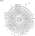
- 48 rotor cores (rotor core segments) and 48 magnets (magnet segments) may be provided.
- each rotor core 500 may be securely fixed to the rotor frame 300.
- the depression 535 may be formed so as to support each rotor core 500 in the mold.
- the depression 535 may include a fixing hole 536, into which a fixing pin 660 (see FIG. 5 ) for fixing each rotor core 500 in the mold during injection molding is inserted. That is, the fixing hole 536 may be a portion of the depression 535.
- the aperture 350 is formed between each magnet 400 and a corresponding rotor core 500.
- the aperture 350 is formed in the outside of the rotor core 500. Consequently, the aperture 350 may be an outer aperture.
- the outer aperture is formed in each side of the rotor core 500.
- the circumferential width of the outer aperture may be smaller than the radial width of the outer aperture.
- the radial width of the outer aperture may be about 3.2 mm.
- a length of about 3.2 mm of the circumferential side surface of the magnet 400 may not contact the rotor core 500, thus forming the aperture.
- the inner apertures 550 and 560 may include a first inner aperture 550 and a second inner aperture 560.
- the first inner aperture 550 may be located further inward than the second inner aperture 560 in the radial direction.
- the radial width of the first core rib 555 may be larger than the radial width of the second core rib 565. That is, the radial width of the second core rib 565 may be minimized. The reason for this is that the second core rib 565 is provided to form an aperture through which magnetic flux does not flow. In the case in which the radial width of the second core rib 565 is large, magnetic flux is formed through the second core rib 565, which may reduce efficiency.
- the apertures 550 and 560 which are respectively formed by the first core rib 555 and the second core rib 565, may reduce the volume of the rotor core 500.
- the apertures 550 and 560 may have a magnetic flux resistance function. Since the apertures 550 and 560 are formed outside in the radial direction, magnetic flux generated by the magnets 400 may be concentrated inward in the radial direction. Of course, in the case in which the rotor is an inner rotor, magnet flux generated by the magnets 400 may be concentrated outward in the radial direction.
- a fixing pin for supporting the rotor core 500 in the mold during injection molding of the rotor frame is inserted into the fixing hole 536.
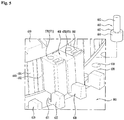
- the lower mold 600 may be provided with fixing pin holes 610, into which fixing pins 660 may be inserted.
- the fixing pins 660 may be inserted into the fixing holes 536 of the rotor cores 500.
- the rotor cores 500 may be fixed in the mold by the fixing pins.
- the shape of the fixing pins is critical. The reason for this is that the fixing pins 660 perform a function of spacing the rotor cores 500 upward from the first bottom surface 630 as well as a function of fixing the rotor cores 500.
- the support surface 663 of the fixing pin 660 protrudes upward from the first bottom surface 630.
- the bottom surface of the rotor core 500 is vertically spaced apart from the first bottom surface 630.
- the molding material is injected into the space to form the bottom surface 332 of the rotary base 330.
- the mold 600 may be provided with support seats 620.
- the fixing holes 536 may be formed in the rotor cores 500.
- the molding material may be injected into the fixing holes 536.
- the lower part of each fixing hole 536 is closed by a corresponding one of the fixing pins 660, but the upper part of each fixing hole 536 is open. Consequently, the molding material may be injected into the upper parts of the fixing holes 536.
- the molding material forms insertion parts 331a.
- the insertion parts 331a protrude from the lower cover 332 or the upper cover 331 toward the fixing holes 536.
- the cover holes 332a are formed in the lower cover 332, rather than in the upper cover 331.
- the insertion parts 331a are integrally formed with the lower cover 332 or the upper cover 331. As a result, the rotor cores 500 may be securely fixed to the rotor frame 300. In particular, the radial movement and the circumferential movement of the rotor cores 500 may be limited by the insertion parts 331a.
- the molding material is injected into the apertures formed in the rotor cores 500.
- the molding material connects the upper cover 331 and the lower cover 332 to form support posts 350, 351, and 352. Consequently, the rotor cores 500 may be securely fixed to the rotor frame 300 by the support posts.
- the cover holes 332a are not formed, and the fixing pins 660 substitute for the cover holes 332a. That is, the fixing pins 660 are integrally formed with the rotor frame 300 in the state in which the fixing pins 660 are disposed in the rotor cores 500. In other words, the fixing pins 660 may be integrally coupled to the rotor frame 300 during injection molding of the rotor frame 300.
- the insertion part 331a contacts the fixing pin 660. Consequently, the insertion part 331a and the fixing pin 660 may be coupled to each other, whereby the rotor cores 500 may be more securely coupled to the rotor frame 300.
- the support posts for interconnecting the lower cover 332 and the upper cover 331 may be further formed.
- the fixing pins 660 protrude from the upper cover 331 or the lower cover 332 of the rotor frame 300.
- the reason for this is that a portion of each of the fixing pins 660 is inserted into a corresponding one of the fixing pin holes 610 of the mold, and the fixing pins 660 protrude by the insertion length after injection molding.
- one rotor core 500 and one magnet 400 may be fixed in the mold by the lower fixing pin, the upper fixing pin, and the support seat. Consequently, the magnets and the rotor cores may be manufactured such that the magnets and the rotor cores are vertically fixed.
- the upper fixing pins are separated from the rotor frame to form the cover holes 331b, through which portions of the upper surfaces of the rotor cores 500 and the magnets 400 may be exposed outward.
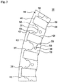
- the extension base 320 includes a plurality of zones D arranged in the circumferential direction.
- the zones D of the extension base 320 are called sub-zones.
- the sub-zones D which have the same shape and size, may be arranged in the circumferential direction to constitute a single extension base 320.
- One sub-zone means a zone constituting a portion of the extension base 320 in one unit zone A. That is, one unit zone A includes one sub-zone D of the extension base 320.
- the crossing ribs 321 are formed so as to cross obliquely in each sub-zone D. That is, one crossing rib 321 extends obliquely and another crossing rib 321 extends obliquely such that the crossing ribs 321 cross each other. Consequently, a zone between the radius defined by the radial inner tips of the crossing ribs and the radius defined by the radial outer tips of the crossing ribs is a sub-zone D.
- the sub-zone D is a crossing zone, since the sub-zone D is a zone defined by the crossing ribs.
- the crossing zone D may withstand force generated between the coupler base 310 and the rotary base 330 in various directions by virtue of the crossing ribs 321.
- a vertical through part 323 is formed between one radial rib 322 and an adjacent radial rib 322.
- the through part 323 is a passage through which air flows. That is, the through part 323 is an air through part.
- specific radial ribs may be formed so as to cross the circumferential centers of the rotor cores 500. That is, the specific radial ribs may further extend from the circumferential centers of the rotor cores 500 in the radial direction in order to form passages sufficient for injection of the molding material into the fixing holes 536 for supporting the rotor cores 500. Specifically, the radial ribs crossing the crossing point B may extend further in the radial direction than the centers of the rotor cores 500.
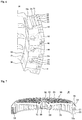
- the rotor frame 300 particularly the coupler base 310 and the extension base 320, includes a reference bottom surface 301 and a reference top surface 302, which define the external shape of the rotor frame 300. That is, the thickness between the reference bottom surface 301 and the reference top surface 302 may be the basic thickness of the coupler base 310 and the extension base 320.
- the present invention has the effect of providing a rotor that can be manufactured with reduced material costs and can be easily handled.
- the present invention has the effect of providing a rotor having a cooling structure that is capable of limiting the increase in temperature of a stator or cooling the stator.
Landscapes
- Engineering & Computer Science (AREA)
- Power Engineering (AREA)
- Manufacturing & Machinery (AREA)
- Textile Engineering (AREA)
- Permanent Field Magnets Of Synchronous Machinery (AREA)
- Lens Barrels (AREA)
- Reciprocating, Oscillating Or Vibrating Motors (AREA)
- Permanent Magnet Type Synchronous Machine (AREA)
- Iron Core Of Rotating Electric Machines (AREA)
Claims (8)
- Rotor (100) für einen Motor, wobei der Rotor (100) aufweist:mehrere Rotorkerne (500);mehrere Magnete (400), die so magnetisiert sind, dass Magnetfluss in Umfangsrichtung gebildet wird, wobei die Magnete (400) und die Rotorkerne (500) in Umfangsrichtung abwechselnd angeordnet sind;eine Kupplung (200), die mit einer Welle verbunden ist; undeinen Rotorrahmen (300) mit einer Kupplungsbasis (310), die mit der Kupplung (200) verbunden ist, einer Verlängerungsbasis (320), die sich von der Kupplungsbasis (310) in Radialrichtung erstreckt, und einer Drehbasis (330), die sich von der Verlängerungsbasis in Axialrichtung der Welle erstreckt, zum Stützen der Rotorkerne (500) und der Magnete (400), während sie die Rotorkerne (500) und die Magnete (400) umgibt,wobei die Kupplungsbasis (310), die Verlängerungsbasis (320) und die Drehbasis (330) durch Spritzgießen in einem Stück ausgebildet sind und der Rotorrahmen (300) mit der Kupplung (200), den Rotorkernen (500) und den Magneten (400) gekoppelt ist,wobei die Verlängerungsbasis (320) mit Kreuzungsrippen (321) versehen ist, die in Radialrichtung kreuzen, die Kreuzungsrippen (321) eine sich schräg erstreckende Kreuzungsrippe (321) und eine weitere Kreuzungsrippe (321) aufweisen, die sich so schräg erstreckt, dass die Kreuzungsrippen (321) einander kreuzen und einen Kreuzungspunkt (B) erzeugen,und die Verlängerungsbasis (320) ferner mit mehreren Radialrippen (322) versehen ist, die sich in Radialrichtung erstrecken und in gleichmäßigen Abständen in Umfangsrichtung angeordnet sind,wobeisich eine erste Radialrippe (322) der Radialrippen (322) durch den Kreuzungspunkt (B) in Radialrichtung erstrecktund eine zweite Radialrippe (322) der Radialrippen (322) mit den entgegengesetzten Umfangsspitzen der Kreuzungsrippen (321) verbunden ist,so dass die Kreuzungsrippen (321) zwischen zweiten Radialrippen (322) vorgesehen sind, die an entgegengesetzten Umfangsseiten der ersten Radialrippen (322) gebildet sind,und so dass sechs Teilstücke (S1, S2, S3, S4, S5, S6) um den Kreuzungspunkt (B) gebildet sind,wobeidie Verlängerungsbasis (320) eine Kreuzungszone (D), die zwischen Radialinnenspitzen der Kreuzungsrippen (321) und Radialaußenspitzen der Kreuzungsrippen (321) gebildet ist, und eine Nichtkreuzungszone aufweist, die außerhalb der Kreuzungszone (D) in Radialrichtung liegt und mit der Drehbasis (330) verbunden ist,wobei die Kreuzungszone (D) und die Nichtkreuzungszone durch Umfangsrippen (324) abgeteilt sind, die in Umfangsrichtung gebildet sind,und wobeiein senkrechtes Durchgangsteil (323) zwischen jeder der Kreuzungsrippen (321) und einer entsprechenden der Radialrippen (322) gebildet ist, um einen Durchgang bereitzustellen, durch den Luft strömt.
- Rotor nach Anspruch 1, wobei der Kreuzungspunkt (B) der Kreuzungsrippen (321) benachbart zu den Radialinnenspitzen der Kreuzungsrippen (321) ist.
- Rotor nach Anspruch 1, wobei
die Durchgangsteile (323) in vier der Teilstücke unter Ausschluss zweier der Teilstücke gebildet sind, die eine kleinste Fläche haben und in Radialrichtung nach innen liegen. - Rotor nach Anspruch 1, wobei die Nichtkreuzungszone mit der Drehbasis (330) über ein Stufenteil (340) verbunden ist.
- Rotor nach Anspruch 1, wobei
Radialrippen (322) von der Kupplungsbasis zur Drehbasis (330) kontinuierlich verbunden sind. - Rotor nach Anspruch 1, wobei sich eine spezifische Radialrippe (322) durch eine Umfangsmitte eines spezifischen der Rotorkerne (500) erstreckt und sich eine benachbarte Radialrippe (322) durch die Umfangsmitte eines Rotorkerns (500) erstreckt, der vom spezifischen Rotorkern in Umfangsrichtung zwei Kerne entfernt liegt, und
wobei die Nichtkreuzungszone mit einer Radialrippe versehen ist, die an einem Mittelteil zwischen den beiden benachbarten Radialrippen so gebildet ist, dass sie sich durch eine Umfangsmitte eines entsprechenden der Rotorkerne erstreckt. - Rotor nach Anspruch 1, wobei die Kupplungsbasis (310) und die Verlängerungsbasis (320) durch Stützrippen abgeteilt sind, die in Umfangsrichtung gebildet sind.
- Rotor nach einem der Ansprüche 1 bis 7, wobeidie Drehbasis (330) so gebildet ist, dass sie Kopfflächen, Bodenflächen und Außenumfangsflächen der Rotorkerne (500) und der Magnete (400) unter Ausschluss von Innenumfangsflächen der Rotorkerne und der Magnete umgibt, die Spalte zwischen den Rotorkernen und einem Stator sowie zwischen den Magneten und dem Stator bilden, oderdie Drehbasis (330) so gebildet ist, dass sie die Kopfflächen, die Bodenflächen und die Innenumfangsflächen der Rotorkerne (500) und der Magnete (400) unter Ausschluss der Außenumfangsflächen der Rotorkerne und der Magnete umgibt, die Spalte zwischen den Rotorkernen und einem Stator sowie zwischen den Magneten und dem Stator bilden.
Applications Claiming Priority (4)
| Application Number | Priority Date | Filing Date | Title |
|---|---|---|---|
| US201562215708P | 2015-09-08 | 2015-09-08 | |
| KR1020160063069A KR101832775B1 (ko) | 2015-09-08 | 2016-05-23 | 로터 및 이를 포함하는 모터 |
| KR1020160063072A KR102597819B1 (ko) | 2015-09-08 | 2016-05-23 | 로터 및 이를 포함하는 모터 |
| PCT/KR2016/010030 WO2017043865A1 (ko) | 2015-09-08 | 2016-09-07 | 로터 및 이를 포함하는 모터 |
Publications (3)
| Publication Number | Publication Date |
|---|---|
| EP3349332A1 EP3349332A1 (de) | 2018-07-18 |
| EP3349332A4 EP3349332A4 (de) | 2019-05-01 |
| EP3349332B1 true EP3349332B1 (de) | 2021-11-17 |
Family
ID=58497859
Family Applications (2)
| Application Number | Title | Priority Date | Filing Date |
|---|---|---|---|
| EP16844676.3A Active EP3349331B1 (de) | 2015-09-08 | 2016-09-07 | Rotor und motor damit |
| EP16844681.3A Active EP3349332B1 (de) | 2015-09-08 | 2016-09-07 | Rotor und motor damit |
Family Applications Before (1)
| Application Number | Title | Priority Date | Filing Date |
|---|---|---|---|
| EP16844676.3A Active EP3349331B1 (de) | 2015-09-08 | 2016-09-07 | Rotor und motor damit |
Country Status (2)
| Country | Link |
|---|---|
| EP (2) | EP3349331B1 (de) |
| KR (4) | KR102597819B1 (de) |
Cited By (1)
| Publication number | Priority date | Publication date | Assignee | Title |
|---|---|---|---|---|
| WO2026028463A1 (ja) * | 2024-07-31 | 2026-02-05 | 三菱電機株式会社 | 磁気ギアード回転電機 |
Families Citing this family (9)
| Publication number | Priority date | Publication date | Assignee | Title |
|---|---|---|---|---|
| CN111463934B (zh) * | 2017-03-29 | 2021-08-24 | 深圳市大疆创新科技有限公司 | 驱动装置及其操作方法、激光测量装置和移动平台 |
| EP3602749A4 (de) | 2017-03-29 | 2020-03-25 | SZ DJI Technology Co., Ltd. | Hohle motorvorrichtungen und zugehörige systeme und verfahren |
| EP3657640B1 (de) * | 2018-11-26 | 2023-09-13 | LG Electronics Inc. | Motor |
| KR102099836B1 (ko) * | 2018-11-26 | 2020-04-10 | 엘지전자 주식회사 | 모터 |
| KR102822634B1 (ko) | 2019-11-28 | 2025-06-20 | 삼성전자주식회사 | 모터 |
| KR102914030B1 (ko) * | 2020-03-06 | 2026-01-16 | 삼성전자주식회사 | 모터 및 이를 구비한 세탁기 |
| WO2022176956A1 (ja) | 2021-02-19 | 2022-08-25 | 宇部興産株式会社 | ポリイミド前駆体組成物およびポリイミドフィルム |
| DE102022111442A1 (de) * | 2022-05-09 | 2023-11-09 | eMoSys GmbH | Fluidgekühlte, mehrphasige permanenterregte Synchronmaschine |
| KR20250179922A (ko) * | 2024-06-24 | 2025-12-31 | 삼성전자주식회사 | 모터 및 의류 처리 장치 |
Citations (1)
| Publication number | Priority date | Publication date | Assignee | Title |
|---|---|---|---|---|
| JP2004194419A (ja) * | 2002-12-11 | 2004-07-08 | Meidensha Corp | 回転電機の回転子構造 |
Family Cites Families (10)
| Publication number | Priority date | Publication date | Assignee | Title |
|---|---|---|---|---|
| JP3725510B2 (ja) * | 2002-10-25 | 2005-12-14 | 株式会社東芝 | 外転形永久磁石モータの回転子 |
| KR100671900B1 (ko) * | 2005-05-23 | 2007-01-24 | 주식회사 대우일렉트로닉스 | 세탁기용 모터의 로터구조 |
| JP2009077602A (ja) * | 2007-09-25 | 2009-04-09 | Hitachi Appliances Inc | 駆動用モータの回転子 |
| JP2012157143A (ja) * | 2011-01-25 | 2012-08-16 | Shinano Kenshi Co Ltd | モータ |
| KR101900456B1 (ko) * | 2011-09-08 | 2018-09-21 | 삼성전자주식회사 | 모터와 이를 가지는 세탁기 |
| US8946954B2 (en) * | 2012-04-20 | 2015-02-03 | Nidec Motor Corporation | Integrated direct drive motor and control |
| WO2013184961A1 (en) * | 2012-06-06 | 2013-12-12 | Nidec Motor Corporation | Motor having spoked outer rotor with spaced apart pole segments |
| KR20140049201A (ko) * | 2012-10-16 | 2014-04-25 | 삼성전자주식회사 | 모터와 이를 가지는 세탁기 |
| CN202918162U (zh) * | 2012-10-31 | 2013-05-01 | 中山大洋电机股份有限公司 | 一种直流无刷外转子电机结构 |
| JP5990475B2 (ja) * | 2013-02-14 | 2016-09-14 | 本田技研工業株式会社 | 回転電機のロータ |
-
2016
- 2016-05-23 KR KR1020160063072A patent/KR102597819B1/ko active Active
- 2016-05-23 KR KR1020160063071A patent/KR102597818B1/ko active Active
- 2016-05-23 KR KR1020160063069A patent/KR101832775B1/ko active Active
- 2016-05-23 KR KR1020160063070A patent/KR102594897B1/ko active Active
- 2016-09-07 EP EP16844676.3A patent/EP3349331B1/de active Active
- 2016-09-07 EP EP16844681.3A patent/EP3349332B1/de active Active
Patent Citations (1)
| Publication number | Priority date | Publication date | Assignee | Title |
|---|---|---|---|---|
| JP2004194419A (ja) * | 2002-12-11 | 2004-07-08 | Meidensha Corp | 回転電機の回転子構造 |
Cited By (1)
| Publication number | Priority date | Publication date | Assignee | Title |
|---|---|---|---|---|
| WO2026028463A1 (ja) * | 2024-07-31 | 2026-02-05 | 三菱電機株式会社 | 磁気ギアード回転電機 |
Also Published As
| Publication number | Publication date |
|---|---|
| KR101832775B1 (ko) | 2018-02-27 |
| KR20170030022A (ko) | 2017-03-16 |
| EP3349332A4 (de) | 2019-05-01 |
| KR20170030019A (ko) | 2017-03-16 |
| KR20170030020A (ko) | 2017-03-16 |
| KR102597819B1 (ko) | 2023-11-03 |
| EP3349332A1 (de) | 2018-07-18 |
| KR20170030021A (ko) | 2017-03-16 |
| EP3349331A1 (de) | 2018-07-18 |
| KR102597818B1 (ko) | 2023-11-03 |
| EP3349331B1 (de) | 2021-05-26 |
| EP3349331A4 (de) | 2019-05-01 |
| KR102594897B1 (ko) | 2023-10-27 |
Similar Documents
| Publication | Publication Date | Title |
|---|---|---|
| EP3349331B1 (de) | Rotor und motor damit | |
| US10326325B2 (en) | Rotor and motor including the same | |
| EP3657639B1 (de) | Motor | |
| JP6325272B2 (ja) | 樹脂ケーシングの成型方法およびモータ | |
| JP5772832B2 (ja) | 回転機 | |
| US10879778B2 (en) | Rotor of rotating electric machine and manufacturing method of the same | |
| US20140232232A1 (en) | Rotary electric machine | |
| CN109391083B (zh) | 马达 | |
| KR102779881B1 (ko) | 모터 | |
| JP6102249B2 (ja) | 単相誘導モータ | |
| US10727710B2 (en) | Motor | |
| KR102487209B1 (ko) | 모터 | |
| EP2722971A2 (de) | Motor und Waschmaschine damit | |
| KR20180018968A (ko) | 회전자 | |
| US10594178B2 (en) | Rotor and motor including the same | |
| KR102026240B1 (ko) | 스포크 구조체가 체결된 모터 및 스포크 구조체 | |
| KR20170138105A (ko) | 스포크 타입 로터 | |
| KR20210071340A (ko) | 구동모터의 고정자 조립 유닛 | |
| KR102351726B1 (ko) | 스포크 타입 로터 | |
| CN116670974A (zh) | 旋转电机 | |
| US20250233467A1 (en) | Rotary Electric Machine | |
| US20240221987A1 (en) | Apparatus for manufacturing rotor | |
| US20140070653A1 (en) | Motor | |
| JP2007074844A (ja) | ステータコア、モータ | |
| JP5149559B2 (ja) | 回転電機 |
Legal Events
| Date | Code | Title | Description |
|---|---|---|---|
| STAA | Information on the status of an ep patent application or granted ep patent |
Free format text: STATUS: THE INTERNATIONAL PUBLICATION HAS BEEN MADE |
|
| PUAI | Public reference made under article 153(3) epc to a published international application that has entered the european phase |
Free format text: ORIGINAL CODE: 0009012 |
|
| STAA | Information on the status of an ep patent application or granted ep patent |
Free format text: STATUS: REQUEST FOR EXAMINATION WAS MADE |
|
| 17P | Request for examination filed |
Effective date: 20180313 |
|
| AK | Designated contracting states |
Kind code of ref document: A1 Designated state(s): AL AT BE BG CH CY CZ DE DK EE ES FI FR GB GR HR HU IE IS IT LI LT LU LV MC MK MT NL NO PL PT RO RS SE SI SK SM TR |
|
| AX | Request for extension of the european patent |
Extension state: BA ME |
|
| DAV | Request for validation of the european patent (deleted) | ||
| DAX | Request for extension of the european patent (deleted) | ||
| A4 | Supplementary search report drawn up and despatched |
Effective date: 20190401 |
|
| RIC1 | Information provided on ipc code assigned before grant |
Ipc: H02K 1/27 20060101AFI20190326BHEP Ipc: H02K 1/30 20060101ALI20190326BHEP Ipc: H02K 1/32 20060101ALN20190326BHEP |
|
| STAA | Information on the status of an ep patent application or granted ep patent |
Free format text: STATUS: EXAMINATION IS IN PROGRESS |
|
| 17Q | First examination report despatched |
Effective date: 20200406 |
|
| RIC1 | Information provided on ipc code assigned before grant |
Ipc: H02K 1/27 20060101AFI20210420BHEP Ipc: H02K 1/30 20060101ALI20210420BHEP Ipc: H02K 1/32 20060101ALN20210420BHEP |
|
| RIC1 | Information provided on ipc code assigned before grant |
Ipc: H02K 1/27 20060101AFI20210423BHEP Ipc: H02K 1/30 20060101ALI20210423BHEP Ipc: H02K 1/32 20060101ALN20210423BHEP |
|
| GRAP | Despatch of communication of intention to grant a patent |
Free format text: ORIGINAL CODE: EPIDOSNIGR1 |
|
| STAA | Information on the status of an ep patent application or granted ep patent |
Free format text: STATUS: GRANT OF PATENT IS INTENDED |
|
| RIC1 | Information provided on ipc code assigned before grant |
Ipc: H02K 1/27 20060101AFI20210517BHEP Ipc: H02K 1/30 20060101ALI20210517BHEP Ipc: H02K 1/32 20060101ALN20210517BHEP |
|
| RIC1 | Information provided on ipc code assigned before grant |
Ipc: H02K 1/27 20060101AFI20210526BHEP Ipc: H02K 1/30 20060101ALI20210526BHEP Ipc: H02K 1/32 20060101ALN20210526BHEP |
|
| INTG | Intention to grant announced |
Effective date: 20210608 |
|
| GRAS | Grant fee paid |
Free format text: ORIGINAL CODE: EPIDOSNIGR3 |
|
| GRAA | (expected) grant |
Free format text: ORIGINAL CODE: 0009210 |
|
| STAA | Information on the status of an ep patent application or granted ep patent |
Free format text: STATUS: THE PATENT HAS BEEN GRANTED |
|
| AK | Designated contracting states |
Kind code of ref document: B1 Designated state(s): AL AT BE BG CH CY CZ DE DK EE ES FI FR GB GR HR HU IE IS IT LI LT LU LV MC MK MT NL NO PL PT RO RS SE SI SK SM TR |
|
| REG | Reference to a national code |
Ref country code: GB Ref legal event code: FG4D |
|
| REG | Reference to a national code |
Ref country code: IE Ref legal event code: FG4D |
|
| REG | Reference to a national code |
Ref country code: DE Ref legal event code: R096 Ref document number: 602016066420 Country of ref document: DE |
|
| REG | Reference to a national code |
Ref country code: AT Ref legal event code: REF Ref document number: 1448851 Country of ref document: AT Kind code of ref document: T Effective date: 20211215 |
|
| REG | Reference to a national code |
Ref country code: LT Ref legal event code: MG9D |
|
| REG | Reference to a national code |
Ref country code: NL Ref legal event code: MP Effective date: 20211117 |
|
| REG | Reference to a national code |
Ref country code: AT Ref legal event code: MK05 Ref document number: 1448851 Country of ref document: AT Kind code of ref document: T Effective date: 20211117 |
|
| PG25 | Lapsed in a contracting state [announced via postgrant information from national office to epo] |
Ref country code: RS Free format text: LAPSE BECAUSE OF FAILURE TO SUBMIT A TRANSLATION OF THE DESCRIPTION OR TO PAY THE FEE WITHIN THE PRESCRIBED TIME-LIMIT Effective date: 20211117 Ref country code: LT Free format text: LAPSE BECAUSE OF FAILURE TO SUBMIT A TRANSLATION OF THE DESCRIPTION OR TO PAY THE FEE WITHIN THE PRESCRIBED TIME-LIMIT Effective date: 20211117 Ref country code: FI Free format text: LAPSE BECAUSE OF FAILURE TO SUBMIT A TRANSLATION OF THE DESCRIPTION OR TO PAY THE FEE WITHIN THE PRESCRIBED TIME-LIMIT Effective date: 20211117 Ref country code: BG Free format text: LAPSE BECAUSE OF FAILURE TO SUBMIT A TRANSLATION OF THE DESCRIPTION OR TO PAY THE FEE WITHIN THE PRESCRIBED TIME-LIMIT Effective date: 20220217 Ref country code: AT Free format text: LAPSE BECAUSE OF FAILURE TO SUBMIT A TRANSLATION OF THE DESCRIPTION OR TO PAY THE FEE WITHIN THE PRESCRIBED TIME-LIMIT Effective date: 20211117 |
|
| PG25 | Lapsed in a contracting state [announced via postgrant information from national office to epo] |
Ref country code: IS Free format text: LAPSE BECAUSE OF FAILURE TO SUBMIT A TRANSLATION OF THE DESCRIPTION OR TO PAY THE FEE WITHIN THE PRESCRIBED TIME-LIMIT Effective date: 20220317 Ref country code: SE Free format text: LAPSE BECAUSE OF FAILURE TO SUBMIT A TRANSLATION OF THE DESCRIPTION OR TO PAY THE FEE WITHIN THE PRESCRIBED TIME-LIMIT Effective date: 20211117 Ref country code: PT Free format text: LAPSE BECAUSE OF FAILURE TO SUBMIT A TRANSLATION OF THE DESCRIPTION OR TO PAY THE FEE WITHIN THE PRESCRIBED TIME-LIMIT Effective date: 20220317 Ref country code: PL Free format text: LAPSE BECAUSE OF FAILURE TO SUBMIT A TRANSLATION OF THE DESCRIPTION OR TO PAY THE FEE WITHIN THE PRESCRIBED TIME-LIMIT Effective date: 20211117 Ref country code: NO Free format text: LAPSE BECAUSE OF FAILURE TO SUBMIT A TRANSLATION OF THE DESCRIPTION OR TO PAY THE FEE WITHIN THE PRESCRIBED TIME-LIMIT Effective date: 20220217 Ref country code: NL Free format text: LAPSE BECAUSE OF FAILURE TO SUBMIT A TRANSLATION OF THE DESCRIPTION OR TO PAY THE FEE WITHIN THE PRESCRIBED TIME-LIMIT Effective date: 20211117 Ref country code: LV Free format text: LAPSE BECAUSE OF FAILURE TO SUBMIT A TRANSLATION OF THE DESCRIPTION OR TO PAY THE FEE WITHIN THE PRESCRIBED TIME-LIMIT Effective date: 20211117 Ref country code: HR Free format text: LAPSE BECAUSE OF FAILURE TO SUBMIT A TRANSLATION OF THE DESCRIPTION OR TO PAY THE FEE WITHIN THE PRESCRIBED TIME-LIMIT Effective date: 20211117 Ref country code: GR Free format text: LAPSE BECAUSE OF FAILURE TO SUBMIT A TRANSLATION OF THE DESCRIPTION OR TO PAY THE FEE WITHIN THE PRESCRIBED TIME-LIMIT Effective date: 20220218 Ref country code: ES Free format text: LAPSE BECAUSE OF FAILURE TO SUBMIT A TRANSLATION OF THE DESCRIPTION OR TO PAY THE FEE WITHIN THE PRESCRIBED TIME-LIMIT Effective date: 20211117 |
|
| PG25 | Lapsed in a contracting state [announced via postgrant information from national office to epo] |
Ref country code: SM Free format text: LAPSE BECAUSE OF FAILURE TO SUBMIT A TRANSLATION OF THE DESCRIPTION OR TO PAY THE FEE WITHIN THE PRESCRIBED TIME-LIMIT Effective date: 20211117 Ref country code: SK Free format text: LAPSE BECAUSE OF FAILURE TO SUBMIT A TRANSLATION OF THE DESCRIPTION OR TO PAY THE FEE WITHIN THE PRESCRIBED TIME-LIMIT Effective date: 20211117 Ref country code: RO Free format text: LAPSE BECAUSE OF FAILURE TO SUBMIT A TRANSLATION OF THE DESCRIPTION OR TO PAY THE FEE WITHIN THE PRESCRIBED TIME-LIMIT Effective date: 20211117 Ref country code: EE Free format text: LAPSE BECAUSE OF FAILURE TO SUBMIT A TRANSLATION OF THE DESCRIPTION OR TO PAY THE FEE WITHIN THE PRESCRIBED TIME-LIMIT Effective date: 20211117 Ref country code: DK Free format text: LAPSE BECAUSE OF FAILURE TO SUBMIT A TRANSLATION OF THE DESCRIPTION OR TO PAY THE FEE WITHIN THE PRESCRIBED TIME-LIMIT Effective date: 20211117 Ref country code: CZ Free format text: LAPSE BECAUSE OF FAILURE TO SUBMIT A TRANSLATION OF THE DESCRIPTION OR TO PAY THE FEE WITHIN THE PRESCRIBED TIME-LIMIT Effective date: 20211117 |
|
| REG | Reference to a national code |
Ref country code: DE Ref legal event code: R097 Ref document number: 602016066420 Country of ref document: DE |
|
| PLBE | No opposition filed within time limit |
Free format text: ORIGINAL CODE: 0009261 |
|
| STAA | Information on the status of an ep patent application or granted ep patent |
Free format text: STATUS: NO OPPOSITION FILED WITHIN TIME LIMIT |
|
| 26N | No opposition filed |
Effective date: 20220818 |
|
| PG25 | Lapsed in a contracting state [announced via postgrant information from national office to epo] |
Ref country code: AL Free format text: LAPSE BECAUSE OF FAILURE TO SUBMIT A TRANSLATION OF THE DESCRIPTION OR TO PAY THE FEE WITHIN THE PRESCRIBED TIME-LIMIT Effective date: 20211117 |
|
| PG25 | Lapsed in a contracting state [announced via postgrant information from national office to epo] |
Ref country code: SI Free format text: LAPSE BECAUSE OF FAILURE TO SUBMIT A TRANSLATION OF THE DESCRIPTION OR TO PAY THE FEE WITHIN THE PRESCRIBED TIME-LIMIT Effective date: 20211117 |
|
| PG25 | Lapsed in a contracting state [announced via postgrant information from national office to epo] |
Ref country code: MC Free format text: LAPSE BECAUSE OF FAILURE TO SUBMIT A TRANSLATION OF THE DESCRIPTION OR TO PAY THE FEE WITHIN THE PRESCRIBED TIME-LIMIT Effective date: 20211117 |
|
| REG | Reference to a national code |
Ref country code: CH Ref legal event code: PL |
|
| REG | Reference to a national code |
Ref country code: BE Ref legal event code: MM Effective date: 20220930 |
|
| P01 | Opt-out of the competence of the unified patent court (upc) registered |
Effective date: 20230524 |
|
| PG25 | Lapsed in a contracting state [announced via postgrant information from national office to epo] |
Ref country code: LU Free format text: LAPSE BECAUSE OF NON-PAYMENT OF DUE FEES Effective date: 20220907 |
|
| PG25 | Lapsed in a contracting state [announced via postgrant information from national office to epo] |
Ref country code: LI Free format text: LAPSE BECAUSE OF NON-PAYMENT OF DUE FEES Effective date: 20220930 Ref country code: IE Free format text: LAPSE BECAUSE OF NON-PAYMENT OF DUE FEES Effective date: 20220907 Ref country code: CH Free format text: LAPSE BECAUSE OF NON-PAYMENT OF DUE FEES Effective date: 20220930 |
|
| PG25 | Lapsed in a contracting state [announced via postgrant information from national office to epo] |
Ref country code: BE Free format text: LAPSE BECAUSE OF NON-PAYMENT OF DUE FEES Effective date: 20220930 |
|
| PG25 | Lapsed in a contracting state [announced via postgrant information from national office to epo] |
Ref country code: HU Free format text: LAPSE BECAUSE OF FAILURE TO SUBMIT A TRANSLATION OF THE DESCRIPTION OR TO PAY THE FEE WITHIN THE PRESCRIBED TIME-LIMIT; INVALID AB INITIO Effective date: 20160907 |
|
| PG25 | Lapsed in a contracting state [announced via postgrant information from national office to epo] |
Ref country code: CY Free format text: LAPSE BECAUSE OF FAILURE TO SUBMIT A TRANSLATION OF THE DESCRIPTION OR TO PAY THE FEE WITHIN THE PRESCRIBED TIME-LIMIT Effective date: 20211117 |
|
| PG25 | Lapsed in a contracting state [announced via postgrant information from national office to epo] |
Ref country code: MK Free format text: LAPSE BECAUSE OF FAILURE TO SUBMIT A TRANSLATION OF THE DESCRIPTION OR TO PAY THE FEE WITHIN THE PRESCRIBED TIME-LIMIT Effective date: 20211117 |
|
| PG25 | Lapsed in a contracting state [announced via postgrant information from national office to epo] |
Ref country code: MT Free format text: LAPSE BECAUSE OF FAILURE TO SUBMIT A TRANSLATION OF THE DESCRIPTION OR TO PAY THE FEE WITHIN THE PRESCRIBED TIME-LIMIT Effective date: 20211117 |
|
| PGFP | Annual fee paid to national office [announced via postgrant information from national office to epo] |
Ref country code: DE Payment date: 20250805 Year of fee payment: 10 |
|
| PGFP | Annual fee paid to national office [announced via postgrant information from national office to epo] |
Ref country code: IT Payment date: 20250806 Year of fee payment: 10 |
|
| PGFP | Annual fee paid to national office [announced via postgrant information from national office to epo] |
Ref country code: GB Payment date: 20250805 Year of fee payment: 10 |
|
| PGFP | Annual fee paid to national office [announced via postgrant information from national office to epo] |
Ref country code: FR Payment date: 20250807 Year of fee payment: 10 |
|
| PG25 | Lapsed in a contracting state [announced via postgrant information from national office to epo] |
Ref country code: TR Free format text: LAPSE BECAUSE OF FAILURE TO SUBMIT A TRANSLATION OF THE DESCRIPTION OR TO PAY THE FEE WITHIN THE PRESCRIBED TIME-LIMIT Effective date: 20211117 |