EP3349367B1 - Verfahren zur bestimmung eines kommunikationsstrahls und entsprechende vorrichtung - Google Patents
Verfahren zur bestimmung eines kommunikationsstrahls und entsprechende vorrichtung Download PDFInfo
- Publication number
- EP3349367B1 EP3349367B1 EP16869846.2A EP16869846A EP3349367B1 EP 3349367 B1 EP3349367 B1 EP 3349367B1 EP 16869846 A EP16869846 A EP 16869846A EP 3349367 B1 EP3349367 B1 EP 3349367B1
- Authority
- EP
- European Patent Office
- Prior art keywords
- beams
- width
- network side
- side device
- downlink
- Prior art date
- Legal status (The legal status is an assumption and is not a legal conclusion. Google has not performed a legal analysis and makes no representation as to the accuracy of the status listed.)
- Active
Links
Images


Classifications
-
- H—ELECTRICITY
- H04—ELECTRIC COMMUNICATION TECHNIQUE
- H04B—TRANSMISSION
- H04B7/00—Radio transmission systems, i.e. using radiation field
- H04B7/02—Diversity systems; Multi-antenna system, i.e. transmission or reception using multiple antennas
- H04B7/04—Diversity systems; Multi-antenna system, i.e. transmission or reception using multiple antennas using two or more spaced independent antennas
- H04B7/06—Diversity systems; Multi-antenna system, i.e. transmission or reception using multiple antennas using two or more spaced independent antennas at the transmitting station
- H04B7/0613—Diversity systems; Multi-antenna system, i.e. transmission or reception using multiple antennas using two or more spaced independent antennas at the transmitting station using simultaneous transmission
- H04B7/0615—Diversity systems; Multi-antenna system, i.e. transmission or reception using multiple antennas using two or more spaced independent antennas at the transmitting station using simultaneous transmission of weighted versions of same signal
- H04B7/0617—Diversity systems; Multi-antenna system, i.e. transmission or reception using multiple antennas using two or more spaced independent antennas at the transmitting station using simultaneous transmission of weighted versions of same signal for beam forming
-
- H—ELECTRICITY
- H04—ELECTRIC COMMUNICATION TECHNIQUE
- H04B—TRANSMISSION
- H04B7/00—Radio transmission systems, i.e. using radiation field
- H04B7/02—Diversity systems; Multi-antenna system, i.e. transmission or reception using multiple antennas
- H04B7/04—Diversity systems; Multi-antenna system, i.e. transmission or reception using multiple antennas using two or more spaced independent antennas
- H04B7/0413—MIMO systems
-
- H—ELECTRICITY
- H04—ELECTRIC COMMUNICATION TECHNIQUE
- H04B—TRANSMISSION
- H04B7/00—Radio transmission systems, i.e. using radiation field
- H04B7/02—Diversity systems; Multi-antenna system, i.e. transmission or reception using multiple antennas
- H04B7/04—Diversity systems; Multi-antenna system, i.e. transmission or reception using multiple antennas using two or more spaced independent antennas
- H04B7/0413—MIMO systems
- H04B7/0417—Feedback systems
-
- H—ELECTRICITY
- H04—ELECTRIC COMMUNICATION TECHNIQUE
- H04B—TRANSMISSION
- H04B7/00—Radio transmission systems, i.e. using radiation field
- H04B7/02—Diversity systems; Multi-antenna system, i.e. transmission or reception using multiple antennas
- H04B7/04—Diversity systems; Multi-antenna system, i.e. transmission or reception using multiple antennas using two or more spaced independent antennas
- H04B7/06—Diversity systems; Multi-antenna system, i.e. transmission or reception using multiple antennas using two or more spaced independent antennas at the transmitting station
- H04B7/0613—Diversity systems; Multi-antenna system, i.e. transmission or reception using multiple antennas using two or more spaced independent antennas at the transmitting station using simultaneous transmission
- H04B7/0615—Diversity systems; Multi-antenna system, i.e. transmission or reception using multiple antennas using two or more spaced independent antennas at the transmitting station using simultaneous transmission of weighted versions of same signal
- H04B7/0619—Diversity systems; Multi-antenna system, i.e. transmission or reception using multiple antennas using two or more spaced independent antennas at the transmitting station using simultaneous transmission of weighted versions of same signal using feedback from receiving side
- H04B7/0621—Feedback content
- H04B7/0626—Channel coefficients, e.g. channel state information [CSI]
-
- H—ELECTRICITY
- H04—ELECTRIC COMMUNICATION TECHNIQUE
- H04B—TRANSMISSION
- H04B7/00—Radio transmission systems, i.e. using radiation field
- H04B7/02—Diversity systems; Multi-antenna system, i.e. transmission or reception using multiple antennas
- H04B7/04—Diversity systems; Multi-antenna system, i.e. transmission or reception using multiple antennas using two or more spaced independent antennas
- H04B7/06—Diversity systems; Multi-antenna system, i.e. transmission or reception using multiple antennas using two or more spaced independent antennas at the transmitting station
- H04B7/0613—Diversity systems; Multi-antenna system, i.e. transmission or reception using multiple antennas using two or more spaced independent antennas at the transmitting station using simultaneous transmission
- H04B7/0615—Diversity systems; Multi-antenna system, i.e. transmission or reception using multiple antennas using two or more spaced independent antennas at the transmitting station using simultaneous transmission of weighted versions of same signal
- H04B7/0619—Diversity systems; Multi-antenna system, i.e. transmission or reception using multiple antennas using two or more spaced independent antennas at the transmitting station using simultaneous transmission of weighted versions of same signal using feedback from receiving side
- H04B7/0621—Feedback content
- H04B7/0628—Diversity capabilities
-
- H—ELECTRICITY
- H04—ELECTRIC COMMUNICATION TECHNIQUE
- H04B—TRANSMISSION
- H04B7/00—Radio transmission systems, i.e. using radiation field
- H04B7/02—Diversity systems; Multi-antenna system, i.e. transmission or reception using multiple antennas
- H04B7/04—Diversity systems; Multi-antenna system, i.e. transmission or reception using multiple antennas using two or more spaced independent antennas
- H04B7/06—Diversity systems; Multi-antenna system, i.e. transmission or reception using multiple antennas using two or more spaced independent antennas at the transmitting station
- H04B7/0613—Diversity systems; Multi-antenna system, i.e. transmission or reception using multiple antennas using two or more spaced independent antennas at the transmitting station using simultaneous transmission
- H04B7/0615—Diversity systems; Multi-antenna system, i.e. transmission or reception using multiple antennas using two or more spaced independent antennas at the transmitting station using simultaneous transmission of weighted versions of same signal
- H04B7/0619—Diversity systems; Multi-antenna system, i.e. transmission or reception using multiple antennas using two or more spaced independent antennas at the transmitting station using simultaneous transmission of weighted versions of same signal using feedback from receiving side
- H04B7/0621—Feedback content
- H04B7/063—Parameters other than those covered in groups H04B7/0623 - H04B7/0634, e.g. channel matrix rank or transmit mode selection
-
- H—ELECTRICITY
- H04—ELECTRIC COMMUNICATION TECHNIQUE
- H04W—WIRELESS COMMUNICATION NETWORKS
- H04W72/00—Local resource management
- H04W72/04—Wireless resource allocation
- H04W72/044—Wireless resource allocation based on the type of the allocated resource
- H04W72/046—Wireless resource allocation based on the type of the allocated resource the resource being in the space domain, e.g. beams
Definitions
- the present invention relates to the field of communications technologies, and in particular, to a communication beam determining method and a corresponding apparatus.
- a massive multiple-input multiple-output (Massive Multiple-Input Multiple-Output, Massive MIMO for short) technology is a latest development direction of a multiple-input multiple-output MIMO technology.
- the Massive MIMO technology can help reduce inter-cell interference and thermal noise, thereby improving spectral efficiency and expanding a system capacity.
- the Massive MIMO technology mainly has two types of implementations.
- a base station uses a wide beam to receive pilot information sent by user equipment (User Equipment, UE for short), and performs precoding (precoding) weighting on transmit data of different UEs based on channel responses of the UEs.
- precoding precoding
- the technology requires that a physical beam corresponding to each channel needs to be a wide beam, and the technology can be applied to only a Time Division Duplex (Time Division Duplexing, TDD for short) system in which UE moves slowly.
- TDD Time Division Duplexing
- the other is a narrow beam-based BF technology.
- a physical beam corresponding to each channel is a narrow beam (that is, widths of physical beams in a horizontal direction and a vertical direction are only a few degrees)
- each narrow beam corresponds to specific user equipment
- a BF weighted value of transmit data is obtained based on a predefined weighted value or a weighted value that changes slowly.
- the narrow beam-based BF technology can be applied to both the TDD system and a Frequency Division Duplex (Frequency Division Duplexing, FDD for short) system, has a wide application range, and is a promising Massive MIMO technology.
- FDD Frequency Division Duplexing
- the narrow beam-based BF technology specifically uses a narrow beam traverse scanning method to determine a beam for data transmission, that is, the base station divides a spatial channel into K narrow beams, and successively transmits a scanning signal by using each narrow beam, and determines the beam for data transmission based on a scanning result fed back by UE.
- a quantity k of narrow beams is proportional to a quantity of antennas, and there is an extremely large quantity of antennas in the Massive MIMO technology. Consequently, the foregoing narrow beam traverse scanning method consumes a long time, and results in large overheads.
- US 2015/0341105 A1 discloses methods for efficient beam training and communications apparatus and network control device utilizing the same.
- WO 2015/141066 A1 discloses a beam selecting method, base station, and user equipment.
- US 2013/0272263 A1 discloses hierarchical channel sounding and channel state information feedback in massive mimo systems.
- WO 2015/141065 A1 discloses a beam selection method, base station, and user device.
- Embodiments of the present invention provide a communication beam determining method and a corresponding apparatus, so as to resolve a prior-art problem that when a narrow beam traverse scanning method is used to determine a communication beam, a long time is consumed and large overheads are caused.
- a communication beam determining method comprising: respectively sending, by a network side device, downlink sounding signals by using M beams with a first width, wherein main lobe directions of any two of the M beams with the first width are different, and M is not less than 2; receiving, by the network side device, sounding results of the downlink sounding signals and that are returned by user equipment, UE, and determining N beams with a second width based on the sounding results, wherein the second width is less than the first width, a coverage area of a set of the N beams with the second width is smaller than a coverage area of a set of the M beams with the first width, and N is not less than 2; and respectively sending, by the network side device, downlink scanning signals by using the N beams with the second width, and determining, based on scanning results that are of the downlink scanning signals and that are returned by the UE, a first beam for data transmission with the UE; wherein after the determining,
- the network side device first scans a spatial channel by using a wider beam, to determine an approximate spatial area (the coverage area of the N beams with the second width) in which the UE is located, and then scans the determined approximate area by using a narrower beam, so as to determine a narrow beam for communication with the UE based on the scanning results.
- the technical solutions provided in this embodiment of the present invention can significantly reduce a channel scanning time, reduce overheads, and improve system efficiency.
- the method further includes: obtaining, by the network side device, channel change information of the UE, where the channel change information may be information characterizing a spatial characteristic direction of a channel, or geographical location information of the UE; generating, by the network side device, at least two tracking beams based on the channel change information and the first beam; and respectively sending, by the network side device, downlink tracking signals by using the at least two tracking beams, and updating, based on tracking results that are of the downlink tracking signals and that are returned by the UE, the beam for data transmission with the UE.
- the network side device can obtain the channel change information, and track and scan the UE based on the channel change information and the beam for current communication, and update the beam for communication with the UE based on the tracking results returned by the UE, to update the communication beam in real time, so that the communication beam conforms to the movement status of the UE, and it is ensured that communication between the UE and the network side device is always in a relatively good state.
- the sounding results include largest received signal strength information of the downlink sounding signals; and the determining, by the network side device, the N beams with the second width based on the sounding results includes: determining, by the network side device, the N beams with the second width based on the second beam, where the coverage area of the set of the N beams with the second width is corresponding to a coverage area of the second beam.
- the network side device directly determines, based on the beam with the first width whose received signal strength is largest, the N beams with the second width for performing scanning. This is easy to be implemented and has a small calculation amount.
- the scanning results include received signal strength information of the downlink scanning signals; and the determining, by the network side device, the first beam based on the scanning results includes: determining, by the network side device, a beam that is in the N beams with the second width and that is corresponding to largest received signal strength of the downlink scanning signals, where the determined beam is the first beam.
- An advantage of the foregoing implementation is that the first beam is determined in an easy manner, and a calculation amount is small.
- the scanning results include received signal strength information of the downlink scanning signals; and the determining, by the network side device, the first beam based on the scanning results includes: updating, by the network side device, channel information based on received signal strength corresponding to each beam with the second width, and determining the first beam based on the channel information.
- An advantage of the foregoing implementation is that quality of communication between the network side device and the UE can be improved as much as possible.
- an embodiment of the present invention provides a communication beam determining method, including: receiving, by UE, at least one of downlink sounding signals that are sent by a network side device by using M beams with a first width, where M is not less than 2; returning, by the UE, a sounding result of the at least one downlink sounding signal to the network side device, where the sounding result is used by the network side device to determine N beams with a second width, the second width is less than the first width, a coverage area of a set of the N beams with the second width is smaller than a coverage area of a set of the M beams with the first width, and N is not less than 2; receiving, by the UE, downlink scanning signals respectively sent by the network side device by using the N beams with the second width; and returning, by the UE, scanning results of the downlink scanning signals to the network side device, where the scanning results are used by the network side device to determine a first beam for data transmission with the UE.
- the method further includes: receiving, by the UE, downlink tracking signals respectively sent by the network side device by using at least two tracking beams, where the at least two tracking beams are generated by the network side device based on channel change information and the first beam; and returning, by the UE, tracking results of the downlink tracking signals to the network side device, where the tracking results are used by the network side device to update the beam for data transmission with the UE.
- an embodiment of the present invention provides a communication beam determining apparatus, including: a sending module, configured to respectively send downlink sounding signals by using M beams with a first width, where main lobe directions of any two of the M beams with the first width are different, and M is not less than 2; a receiving module, configured to receive sounding results that are of the downlink sounding signals and that are returned by user equipment UE; and a processing module, configured to determine N beams with a second width based on the sounding results, where the second width is less than the first width, a coverage area of a set of the N beams with the second width is smaller than a coverage area of a set of the M beams with the first width, and N is not less than 2, where the sending module is further configured to respectively send downlink scanning signals by using the N beams with the second width; the receiving module is further configured to receive scanning results that are of the downlink scanning signals and that are returned by the UE; and the processing module is configured to determine a first beam for data
- the processing module is further configured to: obtain channel change information of the UE; and generate at least two tracking beams based on the channel change information and the first beam; the sending module is further configured to respectively send downlink tracking signals by using the at least two tracking beams; the receiving module is further configured to receive tracking results that are of the downlink tracking signals and that are returned by the UE; and the processing module is further configured to update the beam for data transmission with the UE based on the tracking results returned by the UE.
- the sounding results include information indicating largest received signal strength of the UE for the downlink sounding signals; and the processing module is specifically configured to: determine a second beam that is in the M beams with the first width and that is corresponding to largest received signal strength of the downlink sounding signals; and determine the N beams with the second width based on the second beam, where the coverage area of the set of the N beams with the second width is corresponding to a coverage area of the second beam.
- the scanning results include received signal strength information of the downlink scanning signals; and the processing module is specifically configured to determine a beam that is in the N beams with the second width and that is corresponding to largest received signal strength of the downlink scanning signals, where the determined beam is the first beam.
- the scanning results include received signal strength information of the downlink scanning signals; and the processing module is specifically configured to: update channel information based on received signal strength corresponding to each beam with the second width, and determine the first beam based on the channel information.
- an embodiment of the present invention provides a communication beam determining apparatus, including: a receiving module, configured to receive at least one of downlink sounding signals that are sent by a network side device by using M beams with a first width, where M is not less than 2; a processing module, configured to generate a sounding result of the at least one downlink sounding signal; and a sending module, configured to return the sounding result to the network side device, where the sounding result is used by the network side device to determine N beams with a second width, the second width is less than the first width, a coverage area of a set of the N beams with the second width is smaller than a coverage area of a set of the M beams with the first width, and N is not less than 2; where the receiving module is further configured to receive downlink scanning signals respectively sent by the network side device by using the N beams with the second width; the processing module is further configured to generate scanning results of the downlink scanning signals; and the sending module is further configured to return the scanning results to the network side
- the receiving module is further configured to receive downlink tracking signals respectively sent by the network side device by using at least two tracking beams, where the at least two tracking beams are generated by the network side device based on channel change information and the first beam;
- the processing module is further configured to generate tracking results of the downlink tracking signals;
- the sending module is further configured to return the tracking results to the network side device, where the tracking results are used by the network side device to update the beam for data transmission with the apparatus.
- an embodiment of the present invention provides a communication beam determining device, including: a transceiver, configured to communicate with UE; a memory, configured to store an instruction; and a processor, separately connected to the transceiver and the processor, and configured to execute the instruction stored in the memory, so as to perform the following steps: instructing the transceiver to respectively send downlink sounding signals by using M beams with a first width, where main lobe directions of any two of the M beams with the first width are different, and M is not less than 2; instructing the transceiver to receive sounding results that are of the downlink sounding signals and that are returned by the user equipment UE; determining N beams with a second width based on the sounding results, where the second width is less than the first width, a coverage area of a set of the N beams with the second width is smaller than a coverage area of a set of the M beams with the first width, and N is not less than 2; instructing the transceiver to respectively
- the processor is further configured to: obtain channel change information of the UE; generate at least two tracking beams based on the channel change information and the first beam; and respectively send downlink tracking signals by using the at least two tracking beams, and update, based on tracking results returned by the UE, the beam for the data transmission with the UE.
- the sounding results include largest received signal strength information of the downlink sounding signals; and that the processor is configured to determine the N beams with the second width based on the sounding results is specifically: determining a second beam that is in the M beams with the first width and that is corresponding to largest received signal strength of the downlink sounding signals; and determining the N beams with the second width based on the second beam, where the coverage area of the set of the N beams with the second width is corresponding to a coverage area of the second beam.
- the scanning results include received signal strength information of the downlink scanning signals; and that the processor is configured to determine a first beam for data transmission with the UE based on scanning results returned by the UE is specifically: determining a beam that is in the N beams with the second width and that is corresponding to largest received signal strength of the downlink scanning signals, where the determined beam is the first beam.
- the scanning results include received signal strength information of the downlink scanning signals; and that the processor is configured to determine a first beam for data transmission with the UE based on scanning results returned by the UE is specifically: updating channel information based on received signal strength corresponding to each beam with the second width, and determine the first beam based on the channel information.
- an embodiment of the present invention provides a communication beam determining device, including: a transceiver, configured to communicate with a network side device; a memory, configured to store an instruction; and a processor, separately connected to the transceiver and the processor, and configured to execute the instruction stored in the memory, so as to perform the following steps: receiving at least one downlink sounding signal sent by the network side device by using M beams with a first width, where M is not less than 2; returning a sounding result of the at least one downlink sounding signal to the network side device, where the sounding result is used by the network side device to determine N beams with a second width, the second width is less than the first width, a coverage area of a set of the N beams with the second width is smaller than a coverage area of a set of the M beams with the first width, and N is not less than 2; receiving downlink scanning signals respectively sent by the network side device by using the N beams with the second width; and returning scanning results of the downlink scanning signals
- the processor is further configured to: instruct the transceiver to receive downlink tracking signals respectively sent by the network side device by using at least two tracking beams, where the at least two tracking beams are generated by the network side device based on channel change information and the first beam; and instruct the transceiver to return tracking results of the downlink tracking signals to the network side device, where the tracking results are used by the network side device to update the beam for data transmission with the communication beam determining device.
- the sounding results include received signal strength information of the downlink sounding signals.
- the scanning results include received signal strength information of the downlink scanning signals.
- the technical solutions of the present invention may be applied to various communications systems, such as: a Global System for Mobile Communications (Global System of Mobile communication, GSM for short), a Code Division Multiple Access (Code Division Multiple Access, CDMA for short) system, a Wideband Code Division Multiple Access (Wideband Code Division Multiple Access Wireless, WCDMA for short) system, a general packet radio service (General Packet Radio Service, GPRS for short) system, a Long Term Evolution (Long Term Evolution, LTE for short) system, a Universal Mobile Telecommunication System (Universal Mobile Telecommunication System, UMTS for short), and a 5 th Generation Communication System (5th Generation Communication Systems, 5G for short).
- GSM Global System of Mobile communication
- CDMA Code Division Multiple Access
- WCDMA Wideband Code Division Multiple Access Wireless
- GPRS General Packet Radio Service
- LTE Long Term Evolution
- Universal Mobile Telecommunication System Universal Mobile Telecommunication System
- 5G 5 th Generation Communication Systems
- User equipment UE may also be referred to as a mobile terminal (Mobile Terminal, MT for short), mobile user equipment, and the like, and may communicate with one or more core networks by using a radio access network (for example, Radio Access Network, RAN).
- the user equipment may be a mobile terminal such as a mobile phone (or referred to as a "cellular" phone), and a computer that has a mobile terminal.
- the user equipment may be a portable, pocket-size, handheld, computer-integrated or in-vehicle mobile apparatus, which exchanges voice and/or data with the radio access network.
- a network side device may be a base station in a mobile communications network, or may be a wireless access point (Wireless Access Point, AP for short) in a wireless local area network.
- the base station may be a base transceiver station (Base Transceiver Station, BTS for short) in the GSM or the CDMA, or may be a NodeB (NodeB) in the WCDMA, or may be an evolved NodeB (evolved NodeB, eNB or e-NodeB for short) in the LTE. This is not limited in the present invention.
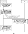
- FIG. 1 is a schematic flowchart of a beam determining method according to Embodiment 1 of the present invention. The method includes the following steps.
- Step 101 A network side device respectively sends downlink sounding signals by using M beams with a first width, where main lobe directions of any two of the M beams with the first width are different, and M is not less than 2.
- Step 102 UE receives at least one downlink sounding signal, and returns a sounding result of the at least one downlink sounding signal to the network side device.
- Step 103 The network side device receives the sounding result returned by the UE, and determines N beams with a second width based on the sounding result, where the second width is less than the first width, a coverage area of a set of the N beams with the second width is smaller than a coverage area of a set of the M beams with the first width, and N is not less than 2.
- Step 104 The network side device respectively sends downlink scanning signals by using the N beams with the second width.
- Step 105 The UE receives the downlink scanning signals, and returns scanning results of the downlink scanning signals to the network side device.
- Step 106 The network side device determines a first beam for data transmission with the UE based on the scanning results returned by the UE.
- the network side device first divides a spatial channel into the M beams with the first width, and sends the downlink sounding signal by using each beam with the first width. It may be understood that the set of the M beams with the first width can cover a cell to which the UE belongs.
- the UE receives one or more of the M downlink sounding signals, and returns the sounding result to the network side device.
- the network side device determines the N beams with the second width based on the sounding result returned by the UE, and then performs scanning by using the N beams with the second width.
- the UE returns, to the network side device, the scanning results of the downlink scanning signals sent by using the N beams with the second width.
- the network side device determines the first beam for communication with the UE based on the scanning results.
- the coverage area of the set of the N beams with the second width is smaller than the coverage area of the set of the M beams with the first width.
- the network side device first scans the spatial channel by using a wider beam, to determine an approximate spatial area in which the UE is located, and then scans the determined approximate area by using a narrower beam, so as to determine a narrow beam for communication with the UE based on the scanning results.
- the technical solutions provided in this embodiment of the present invention can significantly reduce a channel scanning time, reduce overheads, and improve system efficiency.
- the method further includes the following steps.
- Step 107 The network side device obtains channel change information of the UE.
- Step 108 The network side device generates at least two tracking beams based on the channel change information and the first beam.
- Step 109 The network side device respectively sends downlink tracking signals by using the at least two tracking beams.
- Step 110 The UE receives the downlink tracking signals, and returns tracking results of the downlink tracking signals to the network side device.
- Step 111 The network side device updates the beam for data transmission with the UE based on the tracking results returned by the UE.
- the network side device determines the first beam for communication with the UE
- data transmission between the network side device and the UE is implemented by using the first beam.
- the channel change information of the UE is obtained.
- the channel change information may be reported by the UE to the network side device (for example, the UE reports geographical location information of the UE), or the channel change information may be determined by the network side device based on an uplink signal sent by the UE.
- the network side device determines, based on a receive power value fed back by the UE, information used to characterize a spatial characteristic direction.
- the network side device After obtaining the channel change information, the network side device predicates, with reference to the channel change information and the first beam for current communication with the UE, a spatial channel area in which the UE is subsequently located, and generates the at least two tracking beams.
- a set of the at least two tracking beams conforms to a channel change tendency (that is, conforms to a movement status of the UE), and a coverage area of the set of the at least two tracking beams is the predicated spatial channel area in which the UE is located.
- the downlink tracking signals are respectively sent by using the at least two tracking beams, and the beam for communication with the user is updated based on the tracking results fed back by the user.
- the downlink sounding signals, the downlink scanning signals, and the downlink tracking signals in this embodiment of the present invention are all signals for scanning the UE.
- a difference is that beam sets of the downlink sounding signals, the downlink scanning signals, and the downlink tracking signals are different, and beam identifiers carried by the downlink sounding signals, the downlink scanning signals, and the downlink tracking signals are different.
- the network side device can obtain the channel change information, and track and scan the UE based on the channel change information and the beam for current communication, and update the beam for communication with the UE based on the tracking results returned by the UE, to update the communication beam in real time, so that the communication beam conforms to the movement status of the UE, and it is ensured that communication between the UE and the network side device is always in a relatively good state.
- a specific implementation of step 103 in which the network side device receives the sounding result returned by the UE, and determines the N beams with the second width based on the sounding result includes but is not limited to the following implementations:
- the network side device determines a second beam that is in the M beams with the first width and that is corresponding to largest received signal strength, and determines the N beams with the second width based on the second beam.
- the coverage area of the set of N beams with the second width is corresponding to a coverage area of the second beam.
- the UE can receive only one downlink sounding signal sent by using the beam with the first width, and the UE may return an identifier of the beam to the network side device (the identifier may be obtained from the downlink sounding signal). In this case, the network side device may determine that a beam corresponding to the identifier is the second beam.
- the UE may return, to the network side device, an identifier of a beam corresponding to the largest received signal strength, or return received signal strength of each received downlink sounding signal to the network side device.
- the network side device can determine, based on the returned identifier of the beam corresponding to the largest received signal strength or the received signal strength of each received downlink sounding signal, that the beam with the first width that is corresponding to the largest received signal strength is the second beam.
- the received signal strength in this embodiment of the present invention includes but is not limited to downlink receive power.
- the coverage area of the set of the N beams with the second width may be corresponding to the coverage area of the second beam in the following manners: In a first manner, channel space corresponding to the second beam is divided into the N beams with the second width, and the coverage area of the set of the N beams with the second width is equal to the coverage area of the second beam.
- the coverage area of the set of the N beams with the second width includes the coverage area of the second beam, and is slightly larger than the coverage area of the second beam. Such setting can ensure that the set of the N beams with the second width can definitely cover the UE.
- the coverage area of the second beam includes the coverage area of the set of the N beams with the second width, and is slightly larger than the coverage area of the set of the N beams with the second width.
- the previously determined second beam is the beam corresponding to the largest received signal strength for the UE, and therefore, usually the UE is not located at a side edge of the coverage area of the second beam.
- the coverage area of the set of the N beams with the second width is set to be appropriately less than the coverage area of the second beam, so that a scanning area can be narrowed when the UE is covered, thereby reducing a scanning time and improving efficiency.
- the coverage area of the set of the N beams with the second width intersects with the coverage area of the second beam, but neither of them includes the other.
- a purpose of such setting is considering both a requirement for covering the UE and a requirement for narrowing a scanning area, that is, if the UE can infer, based on the sounding result fed back by the UE, that the UE is closer to one side of the coverage area of the second beam, the coverage area of the set of the N beams with the second width may be expanded toward the side that is closer to the UE in the coverage area of the second beam, and a coverage area on the other side may be slightly narrowed.
- the coverage area of the set of the N beams with the second width is corresponding to the coverage area of the second beam indicates but is not limited to a fact that the two are approximately equal, or a fact that the two are equal, or a fact that one includes the other.
- a requirement of setting the coverage area of set of the N beams with the second width is ensuring that the UE is covered.
- the coverage area of the set of the N beams with the second width may be expanded or narrowed based on the coverage area of the second beam.
- Implementation 2 The UE receives downlink sounding signals sent by using r beams in the M beams with the first width, and feeds back received signal strength corresponding to the r beams to the network side device; and the network side device determines the N beams with the second width based on the received signal strength corresponding to the r beams and respective BF weighted values of the r beams.
- the scanning results returned by the UE to the network side device include received signal strength information of the downlink scanning signals.
- Received signal strength may be represented by using downlink receive power of the UE, or may be represented by using another physical quantity that can characterize received signal strength, and details are not described herein.
- That the network side device determines a first beam for data transmission with the UE based on the scanning results returned by the UE includes but is not limited to the following implementations: Manner 1: The network side device determines a beam that is in the N beams with the second width and that is corresponding to largest received signal strength of the downlink scanning signals, and uses the beam as the first beam.
- the network side device determines that the beam corresponding to the largest received signal strength is the first beam. That is, if the largest received signal strength meets a communication requirement, the beam corresponding to the largest received signal strength is directly used as a communication beam (that is, the first beam).
- An advantage of the foregoing Manner 1 is that an implementation is simple, and a calculation amount is small.
- the network side device does not directly select an optimal beam from the N beams with the second width as the first beam for communication, but updates channel information based on received signal strength corresponding to each beam with a second width, and determines the first beam based on the channel information.
- the scanning results fed back by the UE include an angular domain energy matrix H angular of the N beams with the second width that is constructed when the UE receives the downlink scanning signals.
- a spatial channel matrix H space is determined based on H angular
- a BF weighted value of the first beam may be determined based on H space , so as to form the first beam;
- H Space H Angular ⁇ U H s .
- N tx in the foregoing equation is a quantity of antennas
- H space may be determined based on the foregoing expression equation
- a manner of determining the BF weighted value of the first beam based on H space refer to the prior art.
- the network side device updates the channel information in the foregoing Manner 2 based on received signal strength corresponding to each beam with the second width that is returned by the UE, and determines the first beam based on the channel information.
- An advantage of the foregoing Manner 2 is that quality of communication between the network side device and the UE can be improved.
- the method before step 101 in which a network side device respectively sends downlink sounding signals by using M beams with a first width, the method further includes the following step: detecting, by the network side device, UE that newly accesses a network.
- the network side device determines a beam for communication with the UE by using the foregoing step 101 to step 106.
- the network side device when respectively sending the downlink sounding signals by using the M beams with the first width, may successively send a downlink sounding signal on each beam; or may send downlink sounding signals on s beams at a time, and all the downlink sounding signals are sent at M/s times. If M cannot be divisible by s, all the downlink sounding signals are sent at Int([M/s]+1) times. Int(*) is a rounding operator.
- the network side device when respectively sending the downlink scanning signals by using the N beams with the second width, may successively send a downlink scanning signal on each beam, or may send downlink scanning signals on t beams at a time.
- FIG. 3a to FIG. 3d respectively show schematic diagrams of four stages of a network side device: sounding, scanning, data transmission, and channel tracking. The following gives description by using specific embodiments.
- a base station when detecting that UE is a device that newly accesses a network, performs sounding on the UE, so as to learn an approximate channel area in which the UE is located.
- the base station determines a BF weighted value V d corresponding to each of N d downlink sounding signals T d (that is, generates N d beams with a first width).
- V d may be a discrete Fourier transform (discrete Fourier transform, DFT for short) vector, or a linear combination of a plurality of DFT vectors, or another BF weighted value that can cover a cell in which the UE is located.
- the base station sends a scanning signal T s on which weighting is performed by using V s , so as to send scanning signals by using N S beams with a second width
- detected received signal strength of each scanning signal is fed back to the UE.
- the base station directly determines that a BF weighted value of a scanning signal corresponding to largest signal receiving strength is a BF weighted value of a first beam used for communication.
- the base station determines a BF weighted value of a first beam based on a second-order channel characteristic vector direction, that is: the base station determines that the weighted value of the first beam is V j that meets Max V j H R V j , and V j belongs to a DFT vector.
- the network side device performs data transmission with the UE based on the determined first beam.
- the network side device tracks and updates a communication beam.
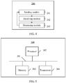
- Embodiment 2 of the present invention provides a communication beam determining apparatus 200.
- the apparatus 200 includes:
- the sending module 201 is further configured to respectively send downlink scanning signals by using the N beams with the second width; the receiving module 202 is further configured to receive scanning results that are of the downlink scanning signals and that are returned by the UE; and the processing module 203 is configured to determine a first beam for data transmission with the UE based on the scanning results.
- the processing module 203 is further configured to: obtain channel change information of the UE, and generate at least two tracking beams based on the channel change information and the first beam; the sending module 201 is further configured to respectively send downlink tracking signals by using the at least two tracking beams; the receiving module 202 is further configured to receive tracking results that are of the downlink tracking signals and that are returned by the UE; and
- the processing module 203 is further configured to update the beam for data transmission with the UE based on the tracking results returned by the UE.
- the sounding results include largest received signal strength information of the downlink sounding signals; and the processing module 203 is specifically configured to: determine a second beam that is in the M beams with the first width and that is corresponding to largest received signal strength of the downlink sounding signals; and determine the N beams with the second width based on the second beam, where the coverage area of the set of the N beams with the second width is corresponding to a coverage area of the second beam.
- the scanning results include received signal strength information of the downlink scanning signals; and the processing module 203 is specifically configured to determine a beam that is in the N beams with the second width and that is corresponding to largest received signal strength of the downlink scanning signals, where the determined beam is the first beam.
- the scanning results include received signal strength information of the downlink scanning signals; and the processing module 203 is specifically configured to: update channel information based on received signal strength corresponding to each beam with the second width, and determine the first beam based on the channel information.
- the sending module 201 may be a transmitter, and the receiving module 202 may be a receiver, and the processing module 203 may be a processor.
- the sending module 201 and the receiving module 202 may be integrated together.
- the apparatus 200 in this embodiment and the communication beam determining method in Embodiment 1 are two aspects based on a same inventive concept, and an implementation process of the method is described in detail above. Therefore, a person skilled in the art may clearly understand a structure and an implementation process of the apparatus 200 in this embodiment based on the foregoing description. For conciseness of this specification, details are not described herein again.
- Embodiment 3 of the present invention provides a communication beam determining apparatus, and the apparatus includes:
- the receiving module is further configured to receive downlink scanning signals respectively sent by the network side device by using the N beams with the second width; the processing module is further configured to generate scanning results of the downlink scanning signals; and the sending module is further configured to return the scanning results to the network side device, where the scanning results are used by the network side device to determine a first beam for data transmission with the communication beam determining apparatus.
- the receiving module is further configured to receive downlink tracking signals respectively sent by the network side device by using at least two tracking beams; the processing module is further configured to generate tracking results of the downlink tracking signals; and the sending module is further configured to return the tracking results to the network side device, where the tracking results are used by the network side device to update the beam for data transmission with the communication beam determining apparatus.
- the sounding result includes received signal strength information of the downlink sounding signal.
- the scanning results include received signal strength information of each of the N downlink scanning signals.
- the communication beam determining apparatus in Embodiment 3 and the communication beam determining method in Embodiment 1 are two aspects based on a same inventive concept, and an implementation process of the method is described in detail above. Therefore, a person skilled in the art may clearly understand a structure and an implementation process of the communication beam determining apparatus in this embodiment based on the foregoing description. For conciseness of this specification, details are not described herein again.
- Embodiment 4 of the present invention provides a communication beam determining device 300.
- the device 300 includes a bus 301, and a processor 302, a memory 303, and a transceiver 304 that are separately connected to the bus 301.
- the transceiver 304 is configured to communicate with UE.
- the memory 303 is configured to store an instruction.
- the processor 302 is configured to execute the instruction stored in the memory 303, so as to perform the following steps:
- the processor 302 is further configured to:
- the sounding results include largest received signal strength information of the downlink sounding signals; and that the processor 302 is configured to determine N beams with a second width based on the sounding results is specifically: determining a second beam that is in the M beams with the first width and that is corresponding to largest received signal strength of the downlink sounding signals; and determine the N beams with the second width based on the second beam, where the coverage area of the set of the N beams with the second width is corresponding to a coverage area of the second beam.
- the scanning results include received signal strength information of the downlink scanning signals; and that the processor 302 is configured to determine a first beam for data transmission with the UE based on scanning results that are of the downlink scanning signals and that are returned by the UE is specifically: determining a beam that is in the N beams with the second width and that is corresponding to largest received signal strength of the downlink scanning signals, where the determined beam is the first beam.
- the scanning results include received signal strength information of the downlink scanning signals; and that the processor 302 is configured to determine a first beam for data transmission with the UE based on scanning results that are of the downlink scanning signals and that are returned by the UE is specifically: updating channel information based on received signal strength corresponding to each beam with the second width, and determining the first beam based on the channel information.
- the transceiver 304 further includes some antennas, and a beam is formed by performing weighting on these antennas.
- the device 300 in Embodiment 4 and the communication beam determining method in Embodiment 1 are two aspects based on a same inventive concept, and an implementation process of the method is described in detail above. Therefore, a person skilled in the art may clearly understand a structure and an implementation process of the device 300 in this embodiment based on the foregoing description. For conciseness of this specification, details are not described herein again.
- Embodiment 5 of the present invention provides a communication beam determining device, including a bus, and a processor, a memory, and a transceiver that are separately connected to the bus.
- the transceiver is configured to communicate with a network side device.
- the memory is configured to store an instruction.
- the processor is configured to execute the instruction stored in the memory 303, so as to perform the following steps:
- the processor is further configured to:
- the sounding results include received signal strength information of the downlink sounding signals.
- the scanning results include received signal strength information of each of the N downlink scanning signals.
- the communication beam determining device in Embodiment 5 and the communication beam determining method in Embodiment 1 are two aspects based on a same inventive concept, and an implementation process of the method is described in detail above. Therefore, a person skilled in the art may clearly understand a structure and an implementation process of the communication beam determining device in this embodiment based on the foregoing description. For conciseness of this specification, details are not described herein again.
- the processor may be one processing unit, or may be a collective term of a plurality of processing units.
- the processor may be a central processing unit (Central Processing Unit, CPU for short), or may be an application specific integrated circuit (Application Specific Integrated Circuit, ASIC for short), or one or more integrated circuits configured to implement this embodiment of the present invention, for example, one or more microprocessors (digital signal processor, DSP for short), or one or more field programmable gate arrays (Field Programmable Gate Array, FPGA for short).
- CPU Central Processing Unit
- ASIC Application Specific Integrated Circuit
- the memory may be a storage apparatus, or may be a collective term of a plurality of storage elements, and is configured to store executable program code, or a parameter, data, or the like required by a user access network device or a terminal for running.
- the memory may include a random access memory (Random Access Memory, RAM for short), and may further include a non-volatile memory (non-volatile memory, NVM for short), for example, a magnetic disk memory or a flash memory (Flash).
- the bus may be an industry standard architecture (Industry Standard Architecture, ISA for short) bus, a peripheral component interconnect (Peripheral Component, PCI for short) bus, an extended industry standard architecture (Extended Industry Standard Architecture, EISA for short) bus, or the like.
- ISA Industry Standard Architecture
- PCI peripheral component interconnect
- EISA Extended Industry Standard Architecture
- the bus may be classified into an address bus, a data bus, a control bus, and the like. For ease of representation, only one line is used in the figure for representation, but it does not indicate that there is only one bus or one type of bus.
- the network side device first scans a spatial channel by using a wider beam, to determine an approximate spatial area in which the UE is located, and then scans the determined approximate area by using a narrower beam, so as to determine a narrow beam for communication with the UE based on the scanning results.
- the technical solutions provided in this embodiment of the present invention can significantly reduce a channel scanning time, reduce overheads, and improve system efficiency.
- the embodiments of the present invention may be provided as a method, a system, or a computer program product. Therefore, the present invention may use a form of hardware only embodiments, software only embodiments, or embodiments with a combination of software and hardware. Moreover, the present invention may use a form of a computer program product that is implemented on one or more computer-usable storage media (including but not limited to a disk memory, a CD-ROM, an optical memory, and the like) that include computer-usable program code.
- computer-usable storage media including but not limited to a disk memory, a CD-ROM, an optical memory, and the like
- These computer program instructions may be provided for a general-purpose computer, a dedicated computer, an embedded processor, or a processor of any other programmable data processing device to generate a machine, so that the instructions executed by a computer or a processor of any other programmable data processing device generate an apparatus for implementing a specific function in one or more processes in the flowcharts and/or in one or more blocks in the block diagrams.
- These computer program instructions may be stored in a computer readable memory that can instruct the computer or any other programmable data processing device to work in a specific manner, so that the instructions stored in the computer readable memory generate an artifact that includes an instruction apparatus.
- the instruction apparatus implements a specific function in one or more processes in the flowcharts and/or in one or more blocks in the block diagrams.
Landscapes
- Engineering & Computer Science (AREA)
- Computer Networks & Wireless Communication (AREA)
- Signal Processing (AREA)
- Physics & Mathematics (AREA)
- Mathematical Physics (AREA)
- Mobile Radio Communication Systems (AREA)
Claims (9)
- Verfahren zum Ermitteln eines Kommunikationsstrahls, umfassend:jeweiliges Senden (101), durch eine netzwerkseitige Vorrichtung, von Downlink-Sondierungssignalen, indem M Strahlen mit einer ersten Breite verwendet werden, wobei Hauptkeulenrichtungen von zwei beliebigen der M Strahlen mit der ersten Breite unterschiedlich sind, und wobei M nicht kleiner als 2 ist;Empfangen (102), in der netzwerkseitigen Vorrichtung, von Sondierungsergebnissen der Downlink-Sondierungssignale, die von einem Benutzergerät (User Equipment, UE) zurückgesendet werden, und Ermitteln von N Strahlen mit einer zweiten Breite aufgrund der Sondierungsergebnisse, wobei die zweite Breite geringer als die erste Breite ist, wobei ein Abdeckungsbereich einer Gruppe der N Strahlen mit der zweiten Breite kleiner als ein Abdeckungsbereich einer Gruppe der M Strahlen mit der ersten Breite ist, und wobei N nicht kleiner als 2 ist; undjeweiliges Senden (104), durch die netzwerkseitige Vorrichtung, von Downlink-Abtastsignalen, indem die N Strahlen mit der zweiten Breite verwendet werden, und Ermitteln aufgrund von Abtastergebnissen, die von den Downlink-Abtastsignalen stammen und die von dem UE zurückgesendet werden, eines ersten Strahls für eine Datenübertragung mit dem UE;wobei das Verfahren, nach dem Ermitteln des ersten Strahls durch die netzwerkseitige Vorrichtung, außerdem umfasst:Erhalten (107), in der netzwerkseitigen Vorrichtung, von Kanaländerungsinformationen des UE, wobei die Kanaländerungsinformationen von dem UE an die netzwerkseitige Vorrichtung gemeldet werden oder von der netzwerkseitigen Vorrichtung aufgrund eines von dem UE gesendeten Uplink-Signals ermittelt werden;Erzeugen, durch die netzwerkseitige Vorrichtung, von mindestens zwei Verfolgungsstrahlen aufgrund von Informationen über einen räumlichen Kanalbereich des UE, die dem räumlichen Kanalbereich entsprechen, in dem sich das UE befindet, und die aus den Kanaländerungsinformationen und aus dem ersten Strahl abgeleitet werden, wobei eine Gruppe aus den mindestens zwei Verfolgungsstrahlen einem Bewegungszustand des UE entspricht und wobei ein Abdeckungsbereich der Gruppe den Informationen über den räumlichen Kanalbereich des UE entspricht; undjeweiliges Senden, durch die netzwerkseitige Vorrichtung, von Downlink-Verfolgungssignalen, indem die mindestens zwei Verfolgungsstrahlen verwendet werden, und Aktualisieren aufgrund von Verfolgungsergebnissen, die von den Downlink-Verfolgungssignalen stammen und die von dem UE zurückgesendet werden, des Strahls für eine Datenübertragung mit dem UE.
- Verfahren nach Anspruch 1, wobei die Sondierungsergebnisse Informationen über die größten empfangenen Signalstärken der Downlink-Sondierungssignale umfassen; und wobei das Ermitteln, durch die netzwerkseitige Vorrichtung, von N Strahlen mit der zweiten Breite aufgrund der Sondierungsergebnisse umfasst:Ermitteln, durch die netzwerkseitige Vorrichtung, eines zweiten Strahls, der aus den M Strahlen mit der ersten Breite stammt und welcher der größten empfangenen Signalstärke der Downlink-Sondierungssignale entspricht; undErmitteln, durch die netzwerkseitige Vorrichtung, der N Strahlen mit der zweiten Breite aufgrund des zweiten Strahls, wobei der Abdeckungsbereich der Gruppe der N Strahlen mit der zweiten Breite einem Abdeckungsbereich des zweiten Strahls entspricht.
- Verfahren nach einem der Ansprüche 1 bis 2, wobei die Abtastergebnisse Informationen über empfangene Signalstärken der Downlink-Abtastsignale umfassen; und wobei das Ermitteln, durch die netzwerkseitige Vorrichtung, des ersten Strahls aufgrund der Abtastergebnisse umfasst:Ermitteln, durch die netzwerkseitige Vorrichtung, eines Strahls, der aus den N Strahlen mit der zweiten Breite stammt und welcher der größten empfangenen Signalstärke der Downlink-Abtastsignale entspricht, wobei der ermittelte Strahl der erste Strahl ist; oderAktualisieren, durch die netzwerkseitige Vorrichtung, der Kanalinformationen aufgrund der empfangenen Signalstärke, die jedem Strahl mit der zweiten Breite entspricht, und Ermitteln des ersten Strahls aufgrund der Kanalinformationen.
- Verfahren zum Ermitteln eines Kommunikationsstrahls, umfassend:Empfangen, in einem Benutzergerät (User Equipment, UE) mindestens eines von Downlink-Sondierungssignalen, die von einer netzwerkseitigen Vorrichtung gesendet werden, indem M Strahlen mit einer ersten Breite verwendet werden, wobei M nicht kleiner als 2 ist;Zurücksenden eines Sondierungsergebnisses des mindestens einen Downlink-Sondierungssignals von dem UE an die netzwerkseitige Vorrichtung, wobei das Sondierungsergebnis von der netzwerkseitigen Vorrichtung verwendet wird, um N Strahlen mit einer zweiten Breite zu ermitteln, wobei die zweite Breite geringer als die erste Breite ist, wobei ein Abdeckungsbereich einer Gruppe der N Strahlen mit der zweiten Breite kleiner als ein Abdeckungsbereich einer Gruppe der M Strahlen mit der ersten Breite ist, und wobei N nicht kleiner als 2 ist;Empfangen, in dem UE, von Downlink-Abtastsignalen, die jeweils von der netzwerkseitigen Vorrichtung gesendet werden, indem die N Strahlen mit der zweiten Breite verwendet werden; undZurücksenden von Abtastergebnissen der Downlink-Abtastsignale von dem UE an die netzwerkseitige Vorrichtung, wobei die Abtastergebnisse von der netzwerkseitigen Vorrichtung verwendet werden, um einen ersten Strahl für eine Datenübertragung mit dem UE zu ermitteln,wobei das Verfahren außerdem umfasst:Empfangen, in dem UE, von Downlink-Verfolgungssignalen, die jeweils von der netzwerkseitigen Vorrichtung gesendet werden, indem mindestens zwei Verfolgungsstrahlen verwendet werden, wobei die mindestens zwei Verfolgungsstrahlen von der netzwerkseitigen Vorrichtung aufgrund von Informationen über einen räumlichen Kanalbereich des UE erzeugt werden, die dem räumlichen Kanalbereich entsprechen, in dem sich das UE befindet, und die aus von dem UE bereitgestellten Kanaländerungsinformationen und aus dem ersten Strahl abgeleitet werden, wobei eine Gruppe aus den mindestens zwei Verfolgungsstrahlen einem Bewegungszustand des UE entspricht und wobei ein Abdeckungsbereich der Gruppe den Informationen über den räumlichen Kanalbereich des UE entspricht; undZurücksenden von Verfolgungsergebnissen der Downlink-Verfolgungssignale von dem UE an die netzwerkseitige Vorrichtung, wobei die Verfolgungsergebnisse von der netzwerkseitigen Vorrichtung verwendet werden, um den Strahl für eine Datenübertragung mit dem UE zu aktualisieren, wobei die Kanaländerungsinformationen von dem UE an die netzwerkseitige Vorrichtung gemeldet werden oder von der netzwerkseitigen Vorrichtung aufgrund eines von dem UE gesendeten Uplink-Signals ermittelt werden.
- Verfahren nach Anspruch 4, wobei das Sondierungsergebnis Informationen über empfangene Signalstärken des mindestens einen Downlink-Sondierungssignals umfasst.
- Verfahren nach Anspruch 4, wobei die Abtastergebnisse Informationen über empfangene Signalstärken von jedem der N Downlink-Abtastsignale umfassen.
- Vorrichtung zum Ermitteln eines Kommunikationsstrahls, umfassend:ein Sendemodul, das konfiguriert ist zum jeweiligen Senden von Downlink-Sondierungssignalen, indem M Strahlen mit einer ersten Breite verwendet werden, wobei Hauptkeulenrichtungen von zwei beliebigen der M Strahlen mit der ersten Breite unterschiedlich sind, und wobei M nicht kleiner als 2 ist;ein Empfangsmodul, das konfiguriert ist zum Empfangen von Sondierungsergebnissen, die von den Downlink-Sondierungssignalen stammen und die von einem Benutzergerät (User Equipment, UE) zurückgesendet werden; undein Verarbeitungsmodul, das konfiguriert ist zum Ermitteln von N Strahlen mit einer zweiten Breite aufgrund der Sondierungsergebnisse, wobei die zweite Breite geringer als die erste Breite ist, wobei ein Abdeckungsbereich einer Gruppe der N Strahlen mit der zweiten Breite kleiner als ein Abdeckungsbereich einer Gruppe der M Strahlen mit der ersten Breite ist, und wobei N nicht kleiner als 2 ist; wobeidas Sendemodul außerdem konfiguriert ist zum jeweiligen Senden von Downlink-Abtastsignalen, indem die N Strahlen mit der zweiten Breite verwendet werden;das Empfangsmodul außerdem konfiguriert ist zum Empfangen von Abtastergebnissen, die von den Downlink-Abtastsignalen stammen und die von dem UE zurückgesendet werden; unddas Verarbeitungsmodul konfiguriert ist zum Ermitteln eines ersten Strahls für eine Datenübertragung mit dem UE aufgrund der Abtastergebnisse,wobei das Verarbeitungsmodul außerdem konfiguriert ist zum: Erhalten von Kanaländerungsinformationen des UE, wobei die Kanaländerungsinformationen von dem UE an die netzwerkseitige Vorrichtung gemeldet werden oder von der netzwerkseitigen Vorrichtung aufgrund eines von dem UE gesendeten Uplink-Signals ermittelt werden; und Erzeugen von mindestens zwei Verfolgungsstrahlen aufgrund von Informationen über einen räumlichen Kanalbereich des UE, die dem räumlichen Kanalbereich entsprechen, in dem sich das UE befindet, und die aus den Kanaländerungsinformationen und aus dem ersten Strahl abgeleitet werden, wobei eine Gruppe aus den mindestens zwei Verfolgungsstrahlen einem Bewegungszustand des UE entspricht und wobei ein Abdeckungsbereich der Gruppe den Informationen über den räumlichen Kanalbereich des UE entspricht; unddas Sendemodul außerdem konfiguriert ist zum jeweiligen Senden von Downlink-Verfolgungssignalen, indem die mindestens zwei Verfolgungsstrahlen verwendet werden;das Empfangsmodul außerdem konfiguriert ist zum Empfangen von Verfolgungsergebnissen, die von den Downlink-Verfolgungssignalen stammen und die von dem UE zurückgesendet werden; unddas Verarbeitungsmodul außerdem konfiguriert ist zum Aktualisieren des Strahls für eine Datenübertragung mit dem UE aufgrund der Verfolgungsergebnisse, die von dem UE zurückgesendet werden.
- Vorrichtung nach Anspruch 7, wobei die Sondierungsergebnisse Informationen über die größten empfangenen Signalstärken der Downlink-Sondierungssignale umfassen; und
wobei das Verarbeitungsmodul insbesondere konfiguriert ist zum: Ermitteln eines zweiten Strahls, der aus den M Strahlen mit der ersten Breite stammt und welcher der größten empfangenen Signalstärke der Downlink-Sondierungssignale entspricht; und Ermitteln der N Strahlen mit der zweiten Breite aufgrund des zweiten Strahls, wobei der Abdeckungsbereich der Gruppe der N Strahlen mit der zweiten Breite einem Abdeckungsbereich des zweiten Strahls entspricht. - Vorrichtung nach einem der Ansprüche 7 oder 8, wobei die Abtastergebnisse Informationen über empfangene Signalstärken der Downlink-Abtastsignale umfassen; und
wobei das Verarbeitungsmodul insbesondere konfiguriert ist zum Ermitteln eines Strahls, der aus den N Strahlen mit der zweiten Breite stammt und welcher der größten empfangenen Signalstärke der Downlink-Abtastsignale entspricht, wobei der ermittelte Strahl der erste Strahl ist; oder konfiguriert ist zum: Aktualisieren der Kanalinformationen aufgrund der empfangenen Signalstärke, die jedem Strahl mit der zweiten Breite entspricht, und Ermitteln des ersten Strahls aufgrund der Kanalinformationen.
Applications Claiming Priority (2)
| Application Number | Priority Date | Filing Date | Title |
|---|---|---|---|
| CN201510860704.0A CN106850009B (zh) | 2015-11-30 | 2015-11-30 | 一种确定通信波束的方法及对应装置 |
| PCT/CN2016/104149 WO2017092536A1 (zh) | 2015-11-30 | 2016-10-31 | 一种确定通信波束的方法及对应装置 |
Publications (3)
| Publication Number | Publication Date |
|---|---|
| EP3349367A1 EP3349367A1 (de) | 2018-07-18 |
| EP3349367A4 EP3349367A4 (de) | 2018-10-31 |
| EP3349367B1 true EP3349367B1 (de) | 2020-02-26 |
Family
ID=58796258
Family Applications (1)
| Application Number | Title | Priority Date | Filing Date |
|---|---|---|---|
| EP16869846.2A Active EP3349367B1 (de) | 2015-11-30 | 2016-10-31 | Verfahren zur bestimmung eines kommunikationsstrahls und entsprechende vorrichtung |
Country Status (4)
| Country | Link |
|---|---|
| US (1) | US10432281B2 (de) |
| EP (1) | EP3349367B1 (de) |
| CN (1) | CN106850009B (de) |
| WO (1) | WO2017092536A1 (de) |
Families Citing this family (15)
| Publication number | Priority date | Publication date | Assignee | Title |
|---|---|---|---|---|
| US10659127B2 (en) * | 2016-05-12 | 2020-05-19 | Lg Electronics Inc. | Method and device for performing beam scanning in wireless access system supporting millimeter wave |
| US10277310B2 (en) * | 2017-02-15 | 2019-04-30 | Viasat, Inc. | Dynamic spatial allocation of satellite capacity based on mobile vessel load forecasting |
| CN109121208B (zh) * | 2017-06-23 | 2023-01-03 | 中国移动通信有限公司研究院 | 一种波束扫描方法和相关设备 |
| EP3646479B1 (de) * | 2017-06-29 | 2020-09-23 | Telefonaktiebolaget LM Ericsson (publ) | Erster funkknoten und verfahren darin zur einstellung einer strahlenreihe zur kommunikation in einem drahtlosen kommunikationsnetzwerk |
| US10686506B2 (en) * | 2017-08-04 | 2020-06-16 | Qualcomm Incorporated | Subset based spatial quasi-colocation parameter indication using multiple beams |
| EP3676966A4 (de) * | 2017-08-30 | 2021-04-21 | Telefonaktiebolaget LM Ericsson (Publ) | Drahtlose vorrichtung zur bestimmung eines optimalen antennenstrahls und verfahren dafür |
| CN108169710A (zh) * | 2017-11-16 | 2018-06-15 | 捷开通讯(深圳)有限公司 | 基于可重构天线的定位方法及定位系统 |
| CN109936397A (zh) * | 2017-12-15 | 2019-06-25 | 北京小米移动软件有限公司 | 波束对准方法及装置 |
| CN109963291B (zh) * | 2017-12-26 | 2021-09-28 | 中国移动通信集团广东有限公司 | 一种覆盖范围自适应调整的方法和基站 |
| CN112425091B (zh) * | 2018-07-30 | 2024-10-29 | 索尼集团公司 | 在无线通信系统中操作设备 |
| KR20200046466A (ko) | 2018-10-24 | 2020-05-07 | 삼성전자주식회사 | 이동 통신 시스템에서 빔 탐색을 위한 방법 및 장치 |
| US11632728B2 (en) | 2019-07-18 | 2023-04-18 | Qualcomm Incorporated | Directional measurements for sidelink synchronization signal transmission |
| CN112448488B (zh) * | 2019-09-04 | 2024-09-03 | 北京小米移动软件有限公司 | 电子设备、充电控制方法及装置、存储介质 |
| CN112787695B (zh) * | 2019-11-08 | 2022-07-26 | 上海华为技术有限公司 | 一种波束宽度控制方法及相关装置 |
| CN116264477A (zh) * | 2021-12-14 | 2023-06-16 | 展讯半导体(南京)有限公司 | 波束扫描方法及装置、计算机可读存储介质 |
Citations (1)
| Publication number | Priority date | Publication date | Assignee | Title |
|---|---|---|---|---|
| WO2015141065A1 (ja) * | 2014-03-20 | 2015-09-24 | 株式会社Nttドコモ | 移動通信システム、基地局、およびユーザ装置 |
Family Cites Families (9)
| Publication number | Priority date | Publication date | Assignee | Title |
|---|---|---|---|---|
| US7612706B2 (en) | 2004-07-16 | 2009-11-03 | Fujitsu Ten Limited | Monopulse radar apparatus and antenna switch |
| CN1866620B (zh) * | 2005-05-18 | 2011-05-25 | 普天信息技术研究院 | 自适应调整智能天线波束宽度的方法 |
| CN101329397B (zh) * | 2007-06-20 | 2012-05-30 | 中国科学院声学研究所 | 一种多波束快速探测方法及装置 |
| GB2471669B (en) | 2009-07-06 | 2012-04-04 | Socowave Technologies Ltd | Wireless network element and method for antenna array control |
| US9414371B2 (en) * | 2012-04-16 | 2016-08-09 | Samsung Electronics Co., Ltd. | Hierarchical channel sounding and channel state information feedback in massive MIMO systems |
| EP3018927B1 (de) | 2013-08-20 | 2017-10-18 | Huawei Technologies Co., Ltd. | Kommunikationsverfahren und -vorrichtung |
| JP2015164281A (ja) * | 2014-01-31 | 2015-09-10 | 株式会社Nttドコモ | ユーザ装置、基地局、及び通信方法 |
| JP2015185953A (ja) | 2014-03-20 | 2015-10-22 | 株式会社Nttドコモ | ビーム選択方法、基地局、およびユーザ装置 |
| US20150341105A1 (en) * | 2014-05-23 | 2015-11-26 | Mediatek Inc. | Methods for efficient beam training and communications apparatus and network control device utilizing the same |
-
2015
- 2015-11-30 CN CN201510860704.0A patent/CN106850009B/zh active Active
-
2016
- 2016-10-31 WO PCT/CN2016/104149 patent/WO2017092536A1/zh not_active Ceased
- 2016-10-31 EP EP16869846.2A patent/EP3349367B1/de active Active
-
2018
- 2018-05-29 US US15/991,672 patent/US10432281B2/en active Active
Patent Citations (2)
| Publication number | Priority date | Publication date | Assignee | Title |
|---|---|---|---|---|
| WO2015141065A1 (ja) * | 2014-03-20 | 2015-09-24 | 株式会社Nttドコモ | 移動通信システム、基地局、およびユーザ装置 |
| EP3122094A1 (de) * | 2014-03-20 | 2017-01-25 | Ntt Docomo, Inc. | Mobilkommunikationssystem, basisstation und benutzervorrichtung |
Also Published As
| Publication number | Publication date |
|---|---|
| US10432281B2 (en) | 2019-10-01 |
| CN106850009A (zh) | 2017-06-13 |
| EP3349367A4 (de) | 2018-10-31 |
| WO2017092536A1 (zh) | 2017-06-08 |
| CN106850009B (zh) | 2021-02-09 |
| EP3349367A1 (de) | 2018-07-18 |
| US20180278311A1 (en) | 2018-09-27 |
Similar Documents
| Publication | Publication Date | Title |
|---|---|---|
| EP3349367B1 (de) | Verfahren zur bestimmung eines kommunikationsstrahls und entsprechende vorrichtung | |
| US11901979B2 (en) | Channel reciprocity-based precoding matrix configuration method and apparatus | |
| EP3963845B1 (de) | Verfahren, verteiltes basisstationssystem, entfernte funkeinheit und basisbandeinheitssystem zur handhabung von uplink-signalen | |
| US11637611B2 (en) | Methods and apparatus for beam management for device communications | |
| EP3096464B1 (de) | Basisstation und strahlformungsverfahren | |
| EP3652870B1 (de) | Frequenzselektives strahlkontrolle | |
| US10020853B2 (en) | Method and system for processing downlink pilot signal | |
| EP2171875B1 (de) | Antennengewichtsberechnung auf der basis der störungszurückweisungsfähigkeiten von benutzern | |
| EP2782263A1 (de) | Signalübertragungsverfahren und -vorrichtung | |
| RU2750572C1 (ru) | Способ и аппаратура обработки сигналов | |
| CN106559118B (zh) | 用于大规模天线下用户终端方位角估计的方法和装置 | |
| US11533094B2 (en) | Systems and methods for providing forced full orthogonality for beams in a MU/MIMO radio system | |
| CN110535579A (zh) | 下行数据的传输方法、网络设备及终端 | |
| EP2938008B1 (de) | Wellenstrahlenauswahlverfahren und basisstation | |
| US20140314011A1 (en) | Method and base station for transmitting signal | |
| US20250023618A1 (en) | Interference suppression in a wireless communication network | |
| US20250357984A1 (en) | Information sending method, information receiving method, communication device, and storage medium | |
| CN117527165A (zh) | 一种信道信息处理方法及装置 | |
| EP3429094B1 (de) | Basisstation | |
| EP3526908B1 (de) | Relative uplink-kanalschätzung | |
| EP3226438B1 (de) | Auf gerichtetem strahl basierendes multithread-übertragungsverfahren mit offener schleife und basisstation | |
| WO2025145302A1 (en) | Beam group reporting in wireless communications | |
| EP4727029A1 (de) | Konfiguration der strahlformung in einem integrierten mess- und kommunikationsnetzwerk | |
| CN115118358B (zh) | 干扰源角度的估计方法、装置、设备和存储介质 | |
| CN117978215A (zh) | 波束确定方法、装置及存储介质 |
Legal Events
| Date | Code | Title | Description |
|---|---|---|---|
| STAA | Information on the status of an ep patent application or granted ep patent |
Free format text: STATUS: THE INTERNATIONAL PUBLICATION HAS BEEN MADE |
|
| PUAI | Public reference made under article 153(3) epc to a published international application that has entered the european phase |
Free format text: ORIGINAL CODE: 0009012 |
|
| STAA | Information on the status of an ep patent application or granted ep patent |
Free format text: STATUS: REQUEST FOR EXAMINATION WAS MADE |
|
| 17P | Request for examination filed |
Effective date: 20180412 |
|
| AK | Designated contracting states |
Kind code of ref document: A1 Designated state(s): AL AT BE BG CH CY CZ DE DK EE ES FI FR GB GR HR HU IE IS IT LI LT LU LV MC MK MT NL NO PL PT RO RS SE SI SK SM TR |
|
| AX | Request for extension of the european patent |
Extension state: BA ME |
|
| REG | Reference to a national code |
Ref country code: DE Ref legal event code: R079 Ref document number: 602016030828 Country of ref document: DE Free format text: PREVIOUS MAIN CLASS: H04B0007040000 Ipc: H04B0007060000 |
|
| A4 | Supplementary search report drawn up and despatched |
Effective date: 20180928 |
|
| RIC1 | Information provided on ipc code assigned before grant |
Ipc: H04B 7/06 20060101AFI20180924BHEP Ipc: H04W 72/04 20090101ALI20180924BHEP |
|
| DAV | Request for validation of the european patent (deleted) | ||
| DAX | Request for extension of the european patent (deleted) | ||
| STAA | Information on the status of an ep patent application or granted ep patent |
Free format text: STATUS: EXAMINATION IS IN PROGRESS |
|
| 17Q | First examination report despatched |
Effective date: 20190717 |
|
| GRAP | Despatch of communication of intention to grant a patent |
Free format text: ORIGINAL CODE: EPIDOSNIGR1 |
|
| STAA | Information on the status of an ep patent application or granted ep patent |
Free format text: STATUS: GRANT OF PATENT IS INTENDED |
|
| INTG | Intention to grant announced |
Effective date: 20191030 |
|
| GRAS | Grant fee paid |
Free format text: ORIGINAL CODE: EPIDOSNIGR3 |
|
| GRAA | (expected) grant |
Free format text: ORIGINAL CODE: 0009210 |
|
| STAA | Information on the status of an ep patent application or granted ep patent |
Free format text: STATUS: THE PATENT HAS BEEN GRANTED |
|
| AK | Designated contracting states |
Kind code of ref document: B1 Designated state(s): AL AT BE BG CH CY CZ DE DK EE ES FI FR GB GR HR HU IE IS IT LI LT LU LV MC MK MT NL NO PL PT RO RS SE SI SK SM TR |
|
| REG | Reference to a national code |
Ref country code: GB Ref legal event code: FG4D |
|
| REG | Reference to a national code |
Ref country code: CH Ref legal event code: EP |
|
| REG | Reference to a national code |
Ref country code: AT Ref legal event code: REF Ref document number: 1238922 Country of ref document: AT Kind code of ref document: T Effective date: 20200315 |
|
| REG | Reference to a national code |
Ref country code: IE Ref legal event code: FG4D |
|
| REG | Reference to a national code |
Ref country code: DE Ref legal event code: R096 Ref document number: 602016030828 Country of ref document: DE |
|
| PG25 | Lapsed in a contracting state [announced via postgrant information from national office to epo] |
Ref country code: NO Free format text: LAPSE BECAUSE OF FAILURE TO SUBMIT A TRANSLATION OF THE DESCRIPTION OR TO PAY THE FEE WITHIN THE PRESCRIBED TIME-LIMIT Effective date: 20200526 Ref country code: RS Free format text: LAPSE BECAUSE OF FAILURE TO SUBMIT A TRANSLATION OF THE DESCRIPTION OR TO PAY THE FEE WITHIN THE PRESCRIBED TIME-LIMIT Effective date: 20200226 Ref country code: FI Free format text: LAPSE BECAUSE OF FAILURE TO SUBMIT A TRANSLATION OF THE DESCRIPTION OR TO PAY THE FEE WITHIN THE PRESCRIBED TIME-LIMIT Effective date: 20200226 |
|
| REG | Reference to a national code |
Ref country code: NL Ref legal event code: MP Effective date: 20200226 |
|
| REG | Reference to a national code |
Ref country code: LT Ref legal event code: MG4D |
|
| PG25 | Lapsed in a contracting state [announced via postgrant information from national office to epo] |
Ref country code: GR Free format text: LAPSE BECAUSE OF FAILURE TO SUBMIT A TRANSLATION OF THE DESCRIPTION OR TO PAY THE FEE WITHIN THE PRESCRIBED TIME-LIMIT Effective date: 20200527 Ref country code: BG Free format text: LAPSE BECAUSE OF FAILURE TO SUBMIT A TRANSLATION OF THE DESCRIPTION OR TO PAY THE FEE WITHIN THE PRESCRIBED TIME-LIMIT Effective date: 20200526 Ref country code: HR Free format text: LAPSE BECAUSE OF FAILURE TO SUBMIT A TRANSLATION OF THE DESCRIPTION OR TO PAY THE FEE WITHIN THE PRESCRIBED TIME-LIMIT Effective date: 20200226 Ref country code: IS Free format text: LAPSE BECAUSE OF FAILURE TO SUBMIT A TRANSLATION OF THE DESCRIPTION OR TO PAY THE FEE WITHIN THE PRESCRIBED TIME-LIMIT Effective date: 20200626 Ref country code: SE Free format text: LAPSE BECAUSE OF FAILURE TO SUBMIT A TRANSLATION OF THE DESCRIPTION OR TO PAY THE FEE WITHIN THE PRESCRIBED TIME-LIMIT Effective date: 20200226 Ref country code: LV Free format text: LAPSE BECAUSE OF FAILURE TO SUBMIT A TRANSLATION OF THE DESCRIPTION OR TO PAY THE FEE WITHIN THE PRESCRIBED TIME-LIMIT Effective date: 20200226 |
|
| PG25 | Lapsed in a contracting state [announced via postgrant information from national office to epo] |
Ref country code: NL Free format text: LAPSE BECAUSE OF FAILURE TO SUBMIT A TRANSLATION OF THE DESCRIPTION OR TO PAY THE FEE WITHIN THE PRESCRIBED TIME-LIMIT Effective date: 20200226 |
|
| PG25 | Lapsed in a contracting state [announced via postgrant information from national office to epo] |
Ref country code: ES Free format text: LAPSE BECAUSE OF FAILURE TO SUBMIT A TRANSLATION OF THE DESCRIPTION OR TO PAY THE FEE WITHIN THE PRESCRIBED TIME-LIMIT Effective date: 20200226 Ref country code: CZ Free format text: LAPSE BECAUSE OF FAILURE TO SUBMIT A TRANSLATION OF THE DESCRIPTION OR TO PAY THE FEE WITHIN THE PRESCRIBED TIME-LIMIT Effective date: 20200226 Ref country code: RO Free format text: LAPSE BECAUSE OF FAILURE TO SUBMIT A TRANSLATION OF THE DESCRIPTION OR TO PAY THE FEE WITHIN THE PRESCRIBED TIME-LIMIT Effective date: 20200226 Ref country code: DK Free format text: LAPSE BECAUSE OF FAILURE TO SUBMIT A TRANSLATION OF THE DESCRIPTION OR TO PAY THE FEE WITHIN THE PRESCRIBED TIME-LIMIT Effective date: 20200226 Ref country code: EE Free format text: LAPSE BECAUSE OF FAILURE TO SUBMIT A TRANSLATION OF THE DESCRIPTION OR TO PAY THE FEE WITHIN THE PRESCRIBED TIME-LIMIT Effective date: 20200226 Ref country code: SM Free format text: LAPSE BECAUSE OF FAILURE TO SUBMIT A TRANSLATION OF THE DESCRIPTION OR TO PAY THE FEE WITHIN THE PRESCRIBED TIME-LIMIT Effective date: 20200226 Ref country code: LT Free format text: LAPSE BECAUSE OF FAILURE TO SUBMIT A TRANSLATION OF THE DESCRIPTION OR TO PAY THE FEE WITHIN THE PRESCRIBED TIME-LIMIT Effective date: 20200226 Ref country code: PT Free format text: LAPSE BECAUSE OF FAILURE TO SUBMIT A TRANSLATION OF THE DESCRIPTION OR TO PAY THE FEE WITHIN THE PRESCRIBED TIME-LIMIT Effective date: 20200719 Ref country code: SK Free format text: LAPSE BECAUSE OF FAILURE TO SUBMIT A TRANSLATION OF THE DESCRIPTION OR TO PAY THE FEE WITHIN THE PRESCRIBED TIME-LIMIT Effective date: 20200226 |
|
| REG | Reference to a national code |
Ref country code: AT Ref legal event code: MK05 Ref document number: 1238922 Country of ref document: AT Kind code of ref document: T Effective date: 20200226 |
|
| REG | Reference to a national code |
Ref country code: DE Ref legal event code: R097 Ref document number: 602016030828 Country of ref document: DE |
|
| PLBE | No opposition filed within time limit |
Free format text: ORIGINAL CODE: 0009261 |
|
| STAA | Information on the status of an ep patent application or granted ep patent |
Free format text: STATUS: NO OPPOSITION FILED WITHIN TIME LIMIT |
|
| PG25 | Lapsed in a contracting state [announced via postgrant information from national office to epo] |
Ref country code: AT Free format text: LAPSE BECAUSE OF FAILURE TO SUBMIT A TRANSLATION OF THE DESCRIPTION OR TO PAY THE FEE WITHIN THE PRESCRIBED TIME-LIMIT Effective date: 20200226 Ref country code: IT Free format text: LAPSE BECAUSE OF FAILURE TO SUBMIT A TRANSLATION OF THE DESCRIPTION OR TO PAY THE FEE WITHIN THE PRESCRIBED TIME-LIMIT Effective date: 20200226 |
|
| PGFP | Annual fee paid to national office [announced via postgrant information from national office to epo] |
Ref country code: GB Payment date: 20201021 Year of fee payment: 5 |
|
| 26N | No opposition filed |
Effective date: 20201127 |
|
| PG25 | Lapsed in a contracting state [announced via postgrant information from national office to epo] |
Ref country code: PL Free format text: LAPSE BECAUSE OF FAILURE TO SUBMIT A TRANSLATION OF THE DESCRIPTION OR TO PAY THE FEE WITHIN THE PRESCRIBED TIME-LIMIT Effective date: 20200226 Ref country code: SI Free format text: LAPSE BECAUSE OF FAILURE TO SUBMIT A TRANSLATION OF THE DESCRIPTION OR TO PAY THE FEE WITHIN THE PRESCRIBED TIME-LIMIT Effective date: 20200226 |
|
| REG | Reference to a national code |
Ref country code: CH Ref legal event code: PL |
|
| PG25 | Lapsed in a contracting state [announced via postgrant information from national office to epo] |
Ref country code: LU Free format text: LAPSE BECAUSE OF NON-PAYMENT OF DUE FEES Effective date: 20201031 Ref country code: MC Free format text: LAPSE BECAUSE OF FAILURE TO SUBMIT A TRANSLATION OF THE DESCRIPTION OR TO PAY THE FEE WITHIN THE PRESCRIBED TIME-LIMIT Effective date: 20200226 |
|
| REG | Reference to a national code |
Ref country code: BE Ref legal event code: MM Effective date: 20201031 |
|
| PG25 | Lapsed in a contracting state [announced via postgrant information from national office to epo] |
Ref country code: FR Free format text: LAPSE BECAUSE OF NON-PAYMENT OF DUE FEES Effective date: 20201031 |
|
| PG25 | Lapsed in a contracting state [announced via postgrant information from national office to epo] |
Ref country code: LI Free format text: LAPSE BECAUSE OF NON-PAYMENT OF DUE FEES Effective date: 20201031 Ref country code: CH Free format text: LAPSE BECAUSE OF NON-PAYMENT OF DUE FEES Effective date: 20201031 Ref country code: BE Free format text: LAPSE BECAUSE OF NON-PAYMENT OF DUE FEES Effective date: 20201031 |
|
| PG25 | Lapsed in a contracting state [announced via postgrant information from national office to epo] |
Ref country code: IE Free format text: LAPSE BECAUSE OF NON-PAYMENT OF DUE FEES Effective date: 20201031 |
|
| PG25 | Lapsed in a contracting state [announced via postgrant information from national office to epo] |
Ref country code: TR Free format text: LAPSE BECAUSE OF FAILURE TO SUBMIT A TRANSLATION OF THE DESCRIPTION OR TO PAY THE FEE WITHIN THE PRESCRIBED TIME-LIMIT Effective date: 20200226 Ref country code: MT Free format text: LAPSE BECAUSE OF FAILURE TO SUBMIT A TRANSLATION OF THE DESCRIPTION OR TO PAY THE FEE WITHIN THE PRESCRIBED TIME-LIMIT Effective date: 20200226 Ref country code: CY Free format text: LAPSE BECAUSE OF FAILURE TO SUBMIT A TRANSLATION OF THE DESCRIPTION OR TO PAY THE FEE WITHIN THE PRESCRIBED TIME-LIMIT Effective date: 20200226 |
|
| GBPC | Gb: european patent ceased through non-payment of renewal fee |
Effective date: 20211031 |
|
| PG25 | Lapsed in a contracting state [announced via postgrant information from national office to epo] |
Ref country code: MK Free format text: LAPSE BECAUSE OF FAILURE TO SUBMIT A TRANSLATION OF THE DESCRIPTION OR TO PAY THE FEE WITHIN THE PRESCRIBED TIME-LIMIT Effective date: 20200226 Ref country code: AL Free format text: LAPSE BECAUSE OF FAILURE TO SUBMIT A TRANSLATION OF THE DESCRIPTION OR TO PAY THE FEE WITHIN THE PRESCRIBED TIME-LIMIT Effective date: 20200226 |
|
| PG25 | Lapsed in a contracting state [announced via postgrant information from national office to epo] |
Ref country code: GB Free format text: LAPSE BECAUSE OF NON-PAYMENT OF DUE FEES Effective date: 20211031 |
|
| PGFP | Annual fee paid to national office [announced via postgrant information from national office to epo] |
Ref country code: DE Payment date: 20250902 Year of fee payment: 10 |