EP3349480B1 - Afficheur vidéo et procédé de fonctionnement correspondant - Google Patents
Afficheur vidéo et procédé de fonctionnement correspondant Download PDFInfo
- Publication number
- EP3349480B1 EP3349480B1 EP17151645.3A EP17151645A EP3349480B1 EP 3349480 B1 EP3349480 B1 EP 3349480B1 EP 17151645 A EP17151645 A EP 17151645A EP 3349480 B1 EP3349480 B1 EP 3349480B1
- Authority
- EP
- European Patent Office
- Prior art keywords
- mic
- sound
- microphones
- video display
- display apparatus
- Prior art date
- Legal status (The legal status is an assumption and is not a legal conclusion. Google has not performed a legal analysis and makes no representation as to the accuracy of the status listed.)
- Active
Links
Images


Classifications
-
- H—ELECTRICITY
- H04—ELECTRIC COMMUNICATION TECHNIQUE
- H04R—LOUDSPEAKERS, MICROPHONES, GRAMOPHONE PICK-UPS OR LIKE ACOUSTIC ELECTROMECHANICAL TRANSDUCERS; ELECTRIC HEARING AIDS; PUBLIC ADDRESS SYSTEMS
- H04R3/00—Circuits for transducers
- H04R3/005—Circuits for transducers for combining the signals of two or more microphones
-
- H—ELECTRICITY
- H04—ELECTRIC COMMUNICATION TECHNIQUE
- H04R—LOUDSPEAKERS, MICROPHONES, GRAMOPHONE PICK-UPS OR LIKE ACOUSTIC ELECTROMECHANICAL TRANSDUCERS; ELECTRIC HEARING AIDS; PUBLIC ADDRESS SYSTEMS
- H04R2499/00—Aspects covered by H04R or H04S not otherwise provided for in their subgroups
- H04R2499/10—General applications
- H04R2499/15—Transducers incorporated in visual displaying devices, e.g. televisions, computer displays, laptops
-
- H—ELECTRICITY
- H04—ELECTRIC COMMUNICATION TECHNIQUE
- H04S—STEREOPHONIC SYSTEMS
- H04S7/00—Indicating arrangements; Control arrangements, e.g. balance control
- H04S7/30—Control circuits for electronic adaptation of the sound field
- H04S7/302—Electronic adaptation of stereophonic sound system to listener position or orientation
- H04S7/303—Tracking of listener position or orientation
Definitions
- the present invention relates to a video display apparatus according to claim 1 and to a method of operating a video display apparatus according to claim 7.
- video display apparatuses such as televisions, video games machines and computer monitors
- a separate device such as a dedicated remote control and/or smart phone.
- a separate device such as a dedicated remote control and/or smart phone.
- sound such as voice commands
- a video display apparatus typically also comprises at least one loudspeaker, which itself emits sound in association with still or moving images displayed on the display screen, for example as a sound track accompanying a film or television programme or as sound effects accompanying a video game.
- EP-A-2 923 634 describes a multi-user voice control system for medical devices, which includes a controller having first and second speech recognition modules and a decision module.
- the system includes a first microphone in communication with the first speech recognition module and a second microphone in communication with the second speech recognition module.
- the first and second speech recognition modules generate respective sets of commands from voice signals received by the respective microphones.
- the decision module assembles a third set of commands from these, which are executed to operate a medical device.
- US-A-2016/0212525 describes a sound source localization device, which has a plurality of sound pickup devices which record a sound signal, and specifies a direction of a sound source based on sound signals recorded by at least two of them.
- US-A-2016/0259305 describes a display device and a method for regulating the viewing angle of a display device, which can rotate a display towards a viewer according to the location of their voice as determined from at least three voice receiving devices of the display device.
- US 2007/0019803 describes a loudspeaker-microphone system with echo cancellation and a corresponding method for echo cancellation.
- the loudspeaker-microphone system comprises a two-way sound reproduction system, which in one possible embodiment can be a TV with voice control or communication.
- WO 2014/064325 describes a media remixing system, and discloses examples of multi-view screens which may be operationally connected to viewer tracking in such a manner that the displayed views depend on viewer's position, distance and/or direction of gaze relative to the screen.
- the object of the invention is solved by a video display apparatus according to claim 1.
- the video display apparatus at least comprises a display screen, at least one loudspeaker for emitting a sound in association with at least one still or moving image displayed on the display screen, at least two spatially separated microphones, an audio signal processing unit configured to separate the sound emitted by the loudspeaker and received by the microphones from sound received by the microphones, a sound source locating unit, a voice recognition unit, a voice command execution unit, and a multi-view display unit configured to display at least two different still or moving images on the same area of the display screen simultaneously.
- the voice command execution unit is configured to execute a command in relation to at least one of: a respective one of the simultaneously displayed still or moving images, and a sound signal generated by the video display apparatus.
- the command is executed according to a location of a sound source issuing the command identified by the sound source locating unit.
- a video display apparatus is relatively much larger than a portable device like a remote control unit or a smart phone, so that the at least two microphones can be positioned sufficiently far apart from each other to give good spatial resolution for discriminating sound sources from each other.
- the audio signal processing unit can receive the sound emitted by the loudspeaker directly as an electronic signal before, during or after its emission, the sound emitted by the loudspeaker can be separated from the sound received by the microphones with a high degree of certainty and echoes can be easily identified and accounted for.
- At least one of the microphones is preferably located adjacent the display screen, on the same side of the apparatus as the display screen. This improves the chances that at least one of the microphones will be facing a viewer of the display screen. More preferably, at least two of the microphones are located on either side of the display screen with the display screen between them, facing the same direction as the display screen. This is beneficial in increasing the horizontal resolution of the microphones.
- At least one pair of the at least two microphones are spatially separated by at least 400 mm, more preferably by at least 500 mm, more preferably still by at least 600 mm, and most preferably by at least 700 mm from each other. This is advantageous because the spatial resolution of the microphones increases in proportion to their spatial separation.
- the at least two microphones comprise three microphones arranged in a triangle. This is beneficial because it allows sound sources to be discriminated from each other in two dimensions. For example, if the triangle has one horizontal and one vertical side, this will give corresponding spatial resolution of sound sources in the horizontal and vertical directions.
- the sound source locating unit may locate the source of sounds, based upon the differences between the sound signals received by different ones of the at least two microphones. For example, the sound source locating unit may locate the source of sounds based on the different times of arrival of the sound from a single, common source at different ones of the at least two microphones.
- the voice recognition unit is beneficial because it can allow the video display apparatus to adopt one of a plurality of different user profiles according to the voice of a user recognized by the voice recognition unit.
- the voice command execution unit is beneficial because it can allow the video display apparatus to be controlled by a user issuing voice commands, such as "switch to channel A", "increase volume”, and so on, without the need for a separate control device, such as a dedicated remote control or a smart phone. It also allows the video display apparatus to be used in hands-free multimedia and gaming applications.
- Multi-view is an existing display technology allowing at least two different still or moving images to be displayed on the display screen simultaneously, for example by displaying the different images with different polarizations from each other.
- a plurality of viewers with multi-view glasses of correspondingly different polarizations may then watch respective ones of the different still or moving images simultaneously without the need for a split screen.
- one viewer may watch a film or television programme whilst another viewer browses an album of photos or plays a video game on the same display screen.
- one or more viewers may wear head or earphones supplied by the video display apparatus with a respective sound signal appropriate to the image or images being watched by the viewer in question.
- the video display apparatus is beneficial because a plurality of viewers of the display screen may then control whatever they are watching by issuing one or more voice commands which only affect the images they are viewing and/or the sound signal they are receiving and not the different images or sound of another simultaneous viewer. It also allows for display of the different images and/or the corresponding sound signals to be adapted to the respective locations of the simultaneous viewers. For example, the respective images may track the location of a viewer as they move. According to this example, if two simultaneous viewers swap positions, one of the viewers may call out "I'm over here" as a voice command, and the video display apparatus may then redirect the displayed images and/or the accompanying sound signals accordingly.
- the video display apparatus may further comprise a television signal receiver. This allows the video display apparatus to display television programmes and for the programmes to be selected and controlled using voice commands, instead of using a separate device, such as a dedicated remote control or smart phone.
- the audio signal processing unit is further configured to separate environmental noise from the sound received by the microphones.
- This is beneficial because it can be used to improve the accuracy of sound source location, voice recognition and execution of voice commands.
- the separation of environmental noise from the sound received by the microphones may be carried out by sampling the sound received by the microphones at times when the loudspeaker of the video display apparatus is silent and when no rapid variations in the volume of sound received by the microphones is detected, which might otherwise be indicative of a user's voice, and then using these samples as examples of environmental noise.
- the present invention further relates to a method of operating a video display apparatus.
- the method at least comprises displaying on a display screen of the apparatus at least two different still or moving images on the same area of the display screen simultaneously, emitting a sound from a loudspeaker of the apparatus in association with displaying at least one of the still or moving images, receiving a sound by at least two spatially separated microphones of the apparatus, separating the sound emitted from the loudspeaker and received by the microphones from the sound received by the microphones, locating at least one source of the sound received by the microphones, recognizing at least one voice in the sound received by the microphones, executing a command issued by the at least one voice according to the location of the sound source issuing the command, wherein the command is executed in relation to at least one of a respective one of the simultaneously displayed still or moving images, and a sound signal generated by the video display apparatus.
- the method further comprises receiving a television signal.
- the method further comprises separating environmental noise from the sound received by the microphones.
- the present invention further relates to a computer program product or a program code or system for executing one or more than one of the herein described methods.
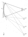
- Fig. 1 schematically shows a plan view of different positions P0, P1, P2, P3 of a viewer relative to a display screen 10 of a video display apparatus. Only when the viewer is positioned somewhere in a plane equidistant between the two horizontal extremities of the display screen 10, is the viewer in a "sweetspot", as represented in Fig. 1 by position P0. In this position, a pair of spatially separated microphones, each respectively located adjacent one of the two horizontal extremities of the display screen 10, will receive the same sound emitted by the viewer as each other. In all other positions, such as those represented by P1, P2, P3 in Fig. 1 , the viewer is at a greater distance from one of the two horizontal extremities of the display screen 10 than from the other.
- the sound received by one of the pair of spatially separated microphones located adjacent one of the horizontal extremities of the display screen 10 will be different from the sound received by the other such microphone so that it is possible to effectively separate the sound emitted by the loudspeaker from a surrounding sound received by the microphones.
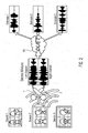
- Fig. 2 schematically represents separating and processing sound signals received from a plurality of different sound sources Source 1, Source 2, Source 3 by stereo microphones 1, 2 by means of an audio signal processing unit 20.
- the stereo microphones 1, 2 produce left and right channel audio signals as illustrated in Fig. 2 .
- the audio signal processing unit 20 compares these left and right channel audio signals and extracts from them estimates Estimate 1, Estimate 2, Estimate 3, each of which respectively corresponds to one of the sounds produced by Source 1, Source 2, Source 3.
- Fig. 3 schematically represents an embodiment of a video display apparatus 100.
- the video display apparatus 100 comprises a display screen 10 and a plurality of spatially separated microphones 1, 2, 3.
- the microphones 1, 2, 3 are located adjacent the display screen and are arranged in a triangle.
- the pair of microphones 1, 2 are spatially separated from each other by more than 400 mm
- the pair of microphones 2, 3 are spatially separated from each other by more than 500 mm
- the pair of microphones 1, 3 are spatially separated from each other by more than 600 mm.
- the video display apparatus 100 further comprises several loudspeakers (not visible in Fig. 3 ) for emitting a sound in association with the display of at least one still or moving image on the display screen 10.
- the video display apparatus 100 also contains a television receiver and an audio signal processing unit, neither of which are visible in Fig. 3 .
- the audio signal processing unit is configured to separate the sound emitted by the loudspeakers from a sound received by the microphones 1, 2, 3.
- Fig. 4 schematically represents a method of calculating the distances in three-dimensions of a plurality of spatially separated microphones, Mic 0, Mic 1, Mic 2, Mic 3 from a single source of sound, S.
- the sound source, S is located at co-ordinates x, y, z in an arbitrarily defined three-dimensional Cartesian co-ordinate system and emits a sound at time, t.
- the plurality of spatially separated microphones, Mic 0, Mic 1, Mic 2, Mic 3 comprises four different combinations of three microphones arranged in a triangle.
- Mic 0 is located at co-ordinates x0, y0, z0 and receives the sound from source S at time t0.
- Mic 1 is located at co-ordinates x1, y1, z1 and receives the sound from source S at time t1.
- Mic 2 is located at co-ordinates x2, y2, z2 and receives the sound from source S at time t2.
- Mic 3 is located at co-ordinates x3, y3, z3 and receives the sound from source S at time t3.
- the distance (x0 - x, y0 - y, z0 - z) of Mic 0 from the sound source S is therefore given by the speed of sound, c, multiplied by the difference between the time, t0, of reception of the sound by Mic 0 and the time, t, of its emission: c*(t0 - t).
- the distance of Mic 1 from the sound source S is given by c*(t1 - t)
- the distance of Mic 2 from the sound source S is given by c*(t2 - t)
- the distance of Mic 3 from the sound source S is given by c*(t3 - t).
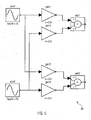
- Fig. 5 schematically represents how two different sound signals respectively received from two different sources of sound may be modelled.
- a first sound signal sine1 having a frequency of 10 Hz is emitted from a first source of sound and a second sound signal sine2 having a frequency of 20 Hz is emitted from a second source of sound.
- sine1 and sine2 are both represented as having a sinusoidal waveform, although in practice, they may have any waveform and any other audio frequency or range of frequencies.
- Sine1 and sine2 are both received by each one of a pair of spatially separated microphones.
- the first microphone may be modelled by two amplifiers gain1, gain2 and by an adder labelled add1 in Fig. 5 .
- Fig. 6 schematically represents two sound signals 61, 62, each respectively received by one of two spatially separated microphones from a single, common source.
- the graph of Fig. 6 plots the amplitude, A, of the two sound signals 61, 62 on the y-axis or ordinate against time, t, on the x-axis or abscissa. As may be seen from Fig.
- the two sound signals 61, 62 have the same frequency as each other and a similar waveform to each other (which, for the sake of this example, is a sinusoid) the amplitude A of the sound signal 61 differs from that of the sound signal 62, since the common source of the two signals 61, 62 is located further from one of the two microphones than the other.
- Fig. 7 schematically represents sound wave power dissipation over distance.
- the graph of Fig. 7 plots the amplitude, A, of a sound wave 71 on the y-axis or ordinate against distance, x, on the x-axis or abscissa from the emission of the sound wave 71 by a source, S, to its reception, R.
- the amplitude, A, of the sound wave 71 progressively diminishes between the source, S, and its reception, R.
- the power of the sound wave 71 which is proportional to the square of the amplitude, A, therefore also dissipates accordingly.
- the present invention provides a video display apparatus at least comprising a display screen, at least one loudspeaker for emitting a sound in association with at least one still or moving image displayed on the display screen, at least two spatially separated microphones, and an audio signal processing unit configured to separate the sound emitted by the loudspeaker from a sound received by the microphones.
- the present invention also provides a method of operating a video display apparatus, wherein the method at least comprises displaying on a display screen of the apparatus at least one still or moving image, emitting a sound from a loudspeaker of the apparatus in association with displaying the at least one still or moving image, receiving a sound by at least two spatially separated microphones of the apparatus, and separating the sound emitted from the loudspeaker from the sound received by the microphones.
- a method allows for three-dimensional localization and separation of sound sources to receive and execute voice commands for control of a video display apparatus, such as a television, without the need for a remote control.
Landscapes
- Health & Medical Sciences (AREA)
- General Health & Medical Sciences (AREA)
- Otolaryngology (AREA)
- Physics & Mathematics (AREA)
- Engineering & Computer Science (AREA)
- Acoustics & Sound (AREA)
- Signal Processing (AREA)
- Testing, Inspecting, Measuring Of Stereoscopic Televisions And Televisions (AREA)
- Circuit For Audible Band Transducer (AREA)
- Controls And Circuits For Display Device (AREA)
Claims (9)
- Un appareil d'affichage vidéo (100) comprenant au moins :un écran d'affichage (10) ;au moins un haut-parleur pour émettre un son en association avec au moins une image fixe ou animée affichée sur l'écran d'affichage (10) ;au moins deux microphones séparés dans l'espace (1, 2, 3 ; Mic 0, Mic 1, Mic 2, Mic 3) ;une unité de traitement du signal audio (20) configurée pour séparer le son émis par le haut-parleur et reçu par les microphones du son reçu par les microphones ;une unité de localisation de la source sonore ;une unité de reconnaissance vocale ;une unité d'exécution des commandes vocales ;une unité d'affichage multi-vues configurée pour afficher simultanément au moins deux images fixes ou animées différentes sur la même zone de l'écran d'affichage (10) ;dans lequel l'unité d'exécution de commande vocale est configurée pour exécuter une commande en relation avec au moins un des éléments suivantsune image respective parmi les images fixes ou animées affichées simultanément, etun signal sonore généré par l'appareil d'affichage vidéo ;dans lequel la commande est exécutée en fonction d'un emplacement d'une source sonore (S) émettant la commande identifiée par l'unité de localisation de la source sonore.
- Appareil d'affichage vidéo selon la revendication 1, dans lequel au moins un des microphones (1, 2, 3 ; Mic 0, Mic 1, Mic 2, Mic 3) est situé à côté de l'écran d'affichage (10), du même côté de l'appareil que l'écran d'affichage.
- Appareil d'affichage vidéo selon la revendication 1 ou la revendication 2, dans lequel au moins une paire (1, 2 ; 2, 3 ; 1, 3) des au moins deux microphones (1, 2, 3 ; Mic 0, Mic 1, Mic 2, Mic 3) sont séparés spatialement l'un de l'autre par au moins 400 mm.
- Appareil d'affichage vidéo selon l'une quelconque des revendications précédentes, dans lequel les au moins deux microphones (1, 2, 3 ; Mic 0, Mic 1, Mic 2, Mic 3) comprennent trois microphones disposés en triangle.
- Appareil d'affichage vidéo selon l'une quelconque des revendications précédentes, comprenant en outre un récepteur de signaux de télévision.
- Appareil d'affichage vidéo selon l'une quelconque des revendications précédentes, dans lequel l'unité de traitement de signal audio (20) est en outre configurée pour séparer le bruit environnemental du son reçu par les microphones (1, 2, 3 ; Mic 0, Mic 1, Mic 2, Mic 3).
- Procédé de fonctionnement d'un appareil d'affichage vidéo (100), le procédé comprenant au moins :l'affichage sur un écran d'affichage (10) de l'appareil d'au moins deux images fixes ou animées différentes sur la même zone de l'écran d'affichage (10) simultanément ;l'émission d'un son à partir d'un haut-parleur de l'appareil en association avec l'affichage d'au moins une des images fixes ou animées ;recevoir un son par au moins deux microphones séparés dans l'espace (1, 2, 3 ; Mic 0, Mic 1, Mic 2, Mic 3) de l'appareil ;la séparation du son émis par le haut-parleur et reçu par les microphones du son reçu par les microphones ;localiser au moins une source (S) du son reçu par les microphones ;reconnaître au moins une voix dans le son reçu par les microphones ;exécuter une commande émise par la au moins une voix en fonction de l'emplacement de la source sonore (S) émettant la commande, dans laquelle la commande est exécutée en relation avec au moins l'un des éléments suivantsl'une des images fixes ou animées affichées simultanément, etun signal sonore généré par l'appareil d'affichage vidéo.
- Procédé selon la revendication 7, comprenant en outre la réception d'un signal de télévision.
- Procédé selon la revendication 7 ou la revendication 8, comprenant en outre la séparation du bruit ambiant du son reçu par les microphones (1, 2, 3 ; Mic 0, Mic 1, Mic 2, Mic 3).
Priority Applications (2)
| Application Number | Priority Date | Filing Date | Title |
|---|---|---|---|
| EP17151645.3A EP3349480B1 (fr) | 2017-01-16 | 2017-01-16 | Afficheur vidéo et procédé de fonctionnement correspondant |
| TR2017/02870A TR201702870A2 (tr) | 2017-01-16 | 2017-02-24 | Vi̇deo görüntüleme aparati ve bunu çaliştirma metodu |
Applications Claiming Priority (1)
| Application Number | Priority Date | Filing Date | Title |
|---|---|---|---|
| EP17151645.3A EP3349480B1 (fr) | 2017-01-16 | 2017-01-16 | Afficheur vidéo et procédé de fonctionnement correspondant |
Publications (2)
| Publication Number | Publication Date |
|---|---|
| EP3349480A1 EP3349480A1 (fr) | 2018-07-18 |
| EP3349480B1 true EP3349480B1 (fr) | 2020-09-02 |
Family
ID=57860671
Family Applications (1)
| Application Number | Title | Priority Date | Filing Date |
|---|---|---|---|
| EP17151645.3A Active EP3349480B1 (fr) | 2017-01-16 | 2017-01-16 | Afficheur vidéo et procédé de fonctionnement correspondant |
Country Status (2)
| Country | Link |
|---|---|
| EP (1) | EP3349480B1 (fr) |
| TR (1) | TR201702870A2 (fr) |
Families Citing this family (1)
| Publication number | Priority date | Publication date | Assignee | Title |
|---|---|---|---|---|
| GB2579112B (en) | 2019-05-31 | 2021-04-21 | Imagination Tech Ltd | Graphics processing units and methods using render progression checks |
Citations (2)
| Publication number | Priority date | Publication date | Assignee | Title |
|---|---|---|---|---|
| US20070019803A1 (en) * | 2003-05-27 | 2007-01-25 | Koninklijke Philips Electronics N.V. | Loudspeaker-microphone system with echo cancellation system and method for echo cancellation |
| WO2014064325A1 (fr) * | 2012-10-26 | 2014-05-01 | Nokia Corporation | Système de re-mélange de milieu |
Family Cites Families (4)
| Publication number | Priority date | Publication date | Assignee | Title |
|---|---|---|---|---|
| JP2007041489A (ja) * | 2004-12-14 | 2007-02-15 | Fujitsu Ten Ltd | 表示装置、枠部材および反射抑制部材 |
| US9293141B2 (en) * | 2014-03-27 | 2016-03-22 | Storz Endoskop Produktions Gmbh | Multi-user voice control system for medical devices |
| CN104240606B (zh) * | 2014-08-22 | 2017-06-16 | 京东方科技集团股份有限公司 | 显示装置及显示装置观看角度的调节方法 |
| JP6613503B2 (ja) * | 2015-01-15 | 2019-12-04 | 本田技研工業株式会社 | 音源定位装置、音響処理システム、及び音源定位装置の制御方法 |
-
2017
- 2017-01-16 EP EP17151645.3A patent/EP3349480B1/fr active Active
- 2017-02-24 TR TR2017/02870A patent/TR201702870A2/tr unknown
Patent Citations (2)
| Publication number | Priority date | Publication date | Assignee | Title |
|---|---|---|---|---|
| US20070019803A1 (en) * | 2003-05-27 | 2007-01-25 | Koninklijke Philips Electronics N.V. | Loudspeaker-microphone system with echo cancellation system and method for echo cancellation |
| WO2014064325A1 (fr) * | 2012-10-26 | 2014-05-01 | Nokia Corporation | Système de re-mélange de milieu |
Also Published As
| Publication number | Publication date |
|---|---|
| EP3349480A1 (fr) | 2018-07-18 |
| TR201702870A2 (tr) | 2018-07-23 |
Similar Documents
| Publication | Publication Date | Title |
|---|---|---|
| US10694313B2 (en) | Audio communication system and method | |
| US10587979B2 (en) | Localization of sound in a speaker system | |
| US8571192B2 (en) | Method and apparatus for improved matching of auditory space to visual space in video teleconferencing applications using window-based displays | |
| US11340861B2 (en) | Systems, devices, and methods of manipulating audio data based on microphone orientation | |
| EP3342187B1 (fr) | Suppression des bruits ambiants | |
| US11234094B2 (en) | Information processing device, information processing method, and information processing system | |
| US20110157327A1 (en) | 3d audio delivery accompanying 3d display supported by viewer/listener position and orientation tracking | |
| JP2013529004A (ja) | 位置追跡を備えるスピーカ | |
| US11586407B2 (en) | Systems, devices, and methods of manipulating audio data based on display orientation | |
| CN109314834A (zh) | 改进介导现实中声音对象的感知 | |
| US20130163952A1 (en) | Video presentation apparatus, video presentation method, video presentation program, and storage medium | |
| KR102454761B1 (ko) | 영상표시장치의 동작 방법 | |
| CN116261093B (zh) | 可动态调整目标聆听点并消除环境物件干扰的音响系统 | |
| CN102057693B (zh) | 内容再现装置及内容再现方法 | |
| WO2021252116A1 (fr) | Systèmes, dispositifs et procédés d'annulation d'écho acoustique basée sur une orientation d'affichage | |
| CN109002272A (zh) | 互动式指向性声音显示系统及互动式指向性声音显示方法 | |
| EP3349480A1 (fr) | Afficheur vidéo et procédé de fonctionnement correspondant | |
| KR102284914B1 (ko) | 프리셋 영상이 구현되는 사운드 트랙킹 시스템 | |
| KR101505099B1 (ko) | 3차원 음향 제공 시스템 | |
| US20220095054A1 (en) | Sound output apparatus and sound output method | |
| KR20060004528A (ko) | 음상 정위 기능을 가진 입체 음향을 생성하는 장치 및 방법 | |
| MXPA99004254A (en) | Method and device for projecting sound sources onto loudspeakers |
Legal Events
| Date | Code | Title | Description |
|---|---|---|---|
| PUAI | Public reference made under article 153(3) epc to a published international application that has entered the european phase |
Free format text: ORIGINAL CODE: 0009012 |
|
| STAA | Information on the status of an ep patent application or granted ep patent |
Free format text: STATUS: THE APPLICATION HAS BEEN PUBLISHED |
|
| AK | Designated contracting states |
Kind code of ref document: A1 Designated state(s): AL AT BE BG CH CY CZ DE DK EE ES FI FR GB GR HR HU IE IS IT LI LT LU LV MC MK MT NL NO PL PT RO RS SE SI SK SM TR |
|
| AX | Request for extension of the european patent |
Extension state: BA ME |
|
| STAA | Information on the status of an ep patent application or granted ep patent |
Free format text: STATUS: REQUEST FOR EXAMINATION WAS MADE |
|
| 17P | Request for examination filed |
Effective date: 20190115 |
|
| RBV | Designated contracting states (corrected) |
Designated state(s): AL AT BE BG CH CY CZ DE DK EE ES FI FR GB GR HR HU IE IS IT LI LT LU LV MC MK MT NL NO PL PT RO RS SE SI SK SM TR |
|
| STAA | Information on the status of an ep patent application or granted ep patent |
Free format text: STATUS: EXAMINATION IS IN PROGRESS |
|
| 17Q | First examination report despatched |
Effective date: 20191025 |
|
| GRAP | Despatch of communication of intention to grant a patent |
Free format text: ORIGINAL CODE: EPIDOSNIGR1 |
|
| STAA | Information on the status of an ep patent application or granted ep patent |
Free format text: STATUS: GRANT OF PATENT IS INTENDED |
|
| INTG | Intention to grant announced |
Effective date: 20200402 |
|
| RIC1 | Information provided on ipc code assigned before grant |
Ipc: H04R 3/00 20060101AFI20200320BHEP Ipc: H04S 7/00 20060101ALN20200320BHEP |
|
| GRAS | Grant fee paid |
Free format text: ORIGINAL CODE: EPIDOSNIGR3 |
|
| GRAA | (expected) grant |
Free format text: ORIGINAL CODE: 0009210 |
|
| STAA | Information on the status of an ep patent application or granted ep patent |
Free format text: STATUS: THE PATENT HAS BEEN GRANTED |
|
| AK | Designated contracting states |
Kind code of ref document: B1 Designated state(s): AL AT BE BG CH CY CZ DE DK EE ES FI FR GB GR HR HU IE IS IT LI LT LU LV MC MK MT NL NO PL PT RO RS SE SI SK SM TR |
|
| REG | Reference to a national code |
Ref country code: GB Ref legal event code: FG4D |
|
| REG | Reference to a national code |
Ref country code: AT Ref legal event code: REF Ref document number: 1310211 Country of ref document: AT Kind code of ref document: T Effective date: 20200915 Ref country code: CH Ref legal event code: EP |
|
| REG | Reference to a national code |
Ref country code: DE Ref legal event code: R096 Ref document number: 602017022587 Country of ref document: DE |
|
| REG | Reference to a national code |
Ref country code: IE Ref legal event code: FG4D |
|
| REG | Reference to a national code |
Ref country code: LT Ref legal event code: MG4D |
|
| PG25 | Lapsed in a contracting state [announced via postgrant information from national office to epo] |
Ref country code: LT Free format text: LAPSE BECAUSE OF FAILURE TO SUBMIT A TRANSLATION OF THE DESCRIPTION OR TO PAY THE FEE WITHIN THE PRESCRIBED TIME-LIMIT Effective date: 20200902 Ref country code: HR Free format text: LAPSE BECAUSE OF FAILURE TO SUBMIT A TRANSLATION OF THE DESCRIPTION OR TO PAY THE FEE WITHIN THE PRESCRIBED TIME-LIMIT Effective date: 20200902 Ref country code: BG Free format text: LAPSE BECAUSE OF FAILURE TO SUBMIT A TRANSLATION OF THE DESCRIPTION OR TO PAY THE FEE WITHIN THE PRESCRIBED TIME-LIMIT Effective date: 20201202 Ref country code: SE Free format text: LAPSE BECAUSE OF FAILURE TO SUBMIT A TRANSLATION OF THE DESCRIPTION OR TO PAY THE FEE WITHIN THE PRESCRIBED TIME-LIMIT Effective date: 20200902 Ref country code: GR Free format text: LAPSE BECAUSE OF FAILURE TO SUBMIT A TRANSLATION OF THE DESCRIPTION OR TO PAY THE FEE WITHIN THE PRESCRIBED TIME-LIMIT Effective date: 20201203 Ref country code: NO Free format text: LAPSE BECAUSE OF FAILURE TO SUBMIT A TRANSLATION OF THE DESCRIPTION OR TO PAY THE FEE WITHIN THE PRESCRIBED TIME-LIMIT Effective date: 20201202 Ref country code: FI Free format text: LAPSE BECAUSE OF FAILURE TO SUBMIT A TRANSLATION OF THE DESCRIPTION OR TO PAY THE FEE WITHIN THE PRESCRIBED TIME-LIMIT Effective date: 20200902 |
|
| REG | Reference to a national code |
Ref country code: NL Ref legal event code: MP Effective date: 20200902 |
|
| REG | Reference to a national code |
Ref country code: AT Ref legal event code: MK05 Ref document number: 1310211 Country of ref document: AT Kind code of ref document: T Effective date: 20200902 |
|
| PG25 | Lapsed in a contracting state [announced via postgrant information from national office to epo] |
Ref country code: RS Free format text: LAPSE BECAUSE OF FAILURE TO SUBMIT A TRANSLATION OF THE DESCRIPTION OR TO PAY THE FEE WITHIN THE PRESCRIBED TIME-LIMIT Effective date: 20200902 Ref country code: LV Free format text: LAPSE BECAUSE OF FAILURE TO SUBMIT A TRANSLATION OF THE DESCRIPTION OR TO PAY THE FEE WITHIN THE PRESCRIBED TIME-LIMIT Effective date: 20200902 Ref country code: PL Free format text: LAPSE BECAUSE OF FAILURE TO SUBMIT A TRANSLATION OF THE DESCRIPTION OR TO PAY THE FEE WITHIN THE PRESCRIBED TIME-LIMIT Effective date: 20200902 |
|
| PG25 | Lapsed in a contracting state [announced via postgrant information from national office to epo] |
Ref country code: SM Free format text: LAPSE BECAUSE OF FAILURE TO SUBMIT A TRANSLATION OF THE DESCRIPTION OR TO PAY THE FEE WITHIN THE PRESCRIBED TIME-LIMIT Effective date: 20200902 Ref country code: EE Free format text: LAPSE BECAUSE OF FAILURE TO SUBMIT A TRANSLATION OF THE DESCRIPTION OR TO PAY THE FEE WITHIN THE PRESCRIBED TIME-LIMIT Effective date: 20200902 Ref country code: CZ Free format text: LAPSE BECAUSE OF FAILURE TO SUBMIT A TRANSLATION OF THE DESCRIPTION OR TO PAY THE FEE WITHIN THE PRESCRIBED TIME-LIMIT Effective date: 20200902 Ref country code: PT Free format text: LAPSE BECAUSE OF FAILURE TO SUBMIT A TRANSLATION OF THE DESCRIPTION OR TO PAY THE FEE WITHIN THE PRESCRIBED TIME-LIMIT Effective date: 20210104 Ref country code: RO Free format text: LAPSE BECAUSE OF FAILURE TO SUBMIT A TRANSLATION OF THE DESCRIPTION OR TO PAY THE FEE WITHIN THE PRESCRIBED TIME-LIMIT Effective date: 20200902 |
|
| PG25 | Lapsed in a contracting state [announced via postgrant information from national office to epo] |
Ref country code: AL Free format text: LAPSE BECAUSE OF FAILURE TO SUBMIT A TRANSLATION OF THE DESCRIPTION OR TO PAY THE FEE WITHIN THE PRESCRIBED TIME-LIMIT Effective date: 20200902 Ref country code: AT Free format text: LAPSE BECAUSE OF FAILURE TO SUBMIT A TRANSLATION OF THE DESCRIPTION OR TO PAY THE FEE WITHIN THE PRESCRIBED TIME-LIMIT Effective date: 20200902 Ref country code: ES Free format text: LAPSE BECAUSE OF FAILURE TO SUBMIT A TRANSLATION OF THE DESCRIPTION OR TO PAY THE FEE WITHIN THE PRESCRIBED TIME-LIMIT Effective date: 20200902 Ref country code: IS Free format text: LAPSE BECAUSE OF FAILURE TO SUBMIT A TRANSLATION OF THE DESCRIPTION OR TO PAY THE FEE WITHIN THE PRESCRIBED TIME-LIMIT Effective date: 20210102 |
|
| REG | Reference to a national code |
Ref country code: DE Ref legal event code: R097 Ref document number: 602017022587 Country of ref document: DE |
|
| PG25 | Lapsed in a contracting state [announced via postgrant information from national office to epo] |
Ref country code: SK Free format text: LAPSE BECAUSE OF FAILURE TO SUBMIT A TRANSLATION OF THE DESCRIPTION OR TO PAY THE FEE WITHIN THE PRESCRIBED TIME-LIMIT Effective date: 20200902 |
|
| PLBE | No opposition filed within time limit |
Free format text: ORIGINAL CODE: 0009261 |
|
| STAA | Information on the status of an ep patent application or granted ep patent |
Free format text: STATUS: NO OPPOSITION FILED WITHIN TIME LIMIT |
|
| 26N | No opposition filed |
Effective date: 20210603 |
|
| PG25 | Lapsed in a contracting state [announced via postgrant information from national office to epo] |
Ref country code: MC Free format text: LAPSE BECAUSE OF FAILURE TO SUBMIT A TRANSLATION OF THE DESCRIPTION OR TO PAY THE FEE WITHIN THE PRESCRIBED TIME-LIMIT Effective date: 20200902 Ref country code: SI Free format text: LAPSE BECAUSE OF FAILURE TO SUBMIT A TRANSLATION OF THE DESCRIPTION OR TO PAY THE FEE WITHIN THE PRESCRIBED TIME-LIMIT Effective date: 20200902 Ref country code: DK Free format text: LAPSE BECAUSE OF FAILURE TO SUBMIT A TRANSLATION OF THE DESCRIPTION OR TO PAY THE FEE WITHIN THE PRESCRIBED TIME-LIMIT Effective date: 20200902 |
|
| REG | Reference to a national code |
Ref country code: CH Ref legal event code: PL |
|
| PG25 | Lapsed in a contracting state [announced via postgrant information from national office to epo] |
Ref country code: LU Free format text: LAPSE BECAUSE OF NON-PAYMENT OF DUE FEES Effective date: 20210116 |
|
| REG | Reference to a national code |
Ref country code: BE Ref legal event code: MM Effective date: 20210131 |
|
| PG25 | Lapsed in a contracting state [announced via postgrant information from national office to epo] |
Ref country code: FR Free format text: LAPSE BECAUSE OF NON-PAYMENT OF DUE FEES Effective date: 20210131 Ref country code: IT Free format text: LAPSE BECAUSE OF FAILURE TO SUBMIT A TRANSLATION OF THE DESCRIPTION OR TO PAY THE FEE WITHIN THE PRESCRIBED TIME-LIMIT Effective date: 20200902 |
|
| PG25 | Lapsed in a contracting state [announced via postgrant information from national office to epo] |
Ref country code: CH Free format text: LAPSE BECAUSE OF NON-PAYMENT OF DUE FEES Effective date: 20210131 Ref country code: LI Free format text: LAPSE BECAUSE OF NON-PAYMENT OF DUE FEES Effective date: 20210131 |
|
| PG25 | Lapsed in a contracting state [announced via postgrant information from national office to epo] |
Ref country code: IE Free format text: LAPSE BECAUSE OF NON-PAYMENT OF DUE FEES Effective date: 20210116 |
|
| PG25 | Lapsed in a contracting state [announced via postgrant information from national office to epo] |
Ref country code: BE Free format text: LAPSE BECAUSE OF NON-PAYMENT OF DUE FEES Effective date: 20210131 |
|
| PG25 | Lapsed in a contracting state [announced via postgrant information from national office to epo] |
Ref country code: NL Free format text: LAPSE BECAUSE OF NON-PAYMENT OF DUE FEES Effective date: 20200923 Ref country code: CY Free format text: LAPSE BECAUSE OF FAILURE TO SUBMIT A TRANSLATION OF THE DESCRIPTION OR TO PAY THE FEE WITHIN THE PRESCRIBED TIME-LIMIT Effective date: 20200902 |
|
| PG25 | Lapsed in a contracting state [announced via postgrant information from national office to epo] |
Ref country code: HU Free format text: LAPSE BECAUSE OF FAILURE TO SUBMIT A TRANSLATION OF THE DESCRIPTION OR TO PAY THE FEE WITHIN THE PRESCRIBED TIME-LIMIT; INVALID AB INITIO Effective date: 20170116 |
|
| PG25 | Lapsed in a contracting state [announced via postgrant information from national office to epo] |
Ref country code: MK Free format text: LAPSE BECAUSE OF FAILURE TO SUBMIT A TRANSLATION OF THE DESCRIPTION OR TO PAY THE FEE WITHIN THE PRESCRIBED TIME-LIMIT Effective date: 20200902 |
|
| PG25 | Lapsed in a contracting state [announced via postgrant information from national office to epo] |
Ref country code: MT Free format text: LAPSE BECAUSE OF FAILURE TO SUBMIT A TRANSLATION OF THE DESCRIPTION OR TO PAY THE FEE WITHIN THE PRESCRIBED TIME-LIMIT Effective date: 20200902 |
|
| PGFP | Annual fee paid to national office [announced via postgrant information from national office to epo] |
Ref country code: GB Payment date: 20260123 Year of fee payment: 10 |
|
| PGFP | Annual fee paid to national office [announced via postgrant information from national office to epo] |
Ref country code: DE Payment date: 20260121 Year of fee payment: 10 |
|
| PGFP | Annual fee paid to national office [announced via postgrant information from national office to epo] |
Ref country code: TR Payment date: 20260114 Year of fee payment: 10 |